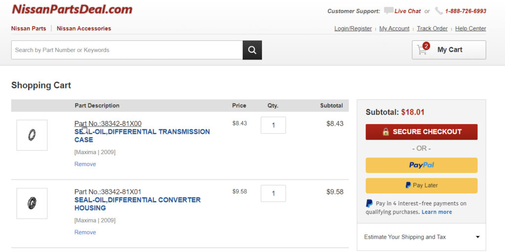
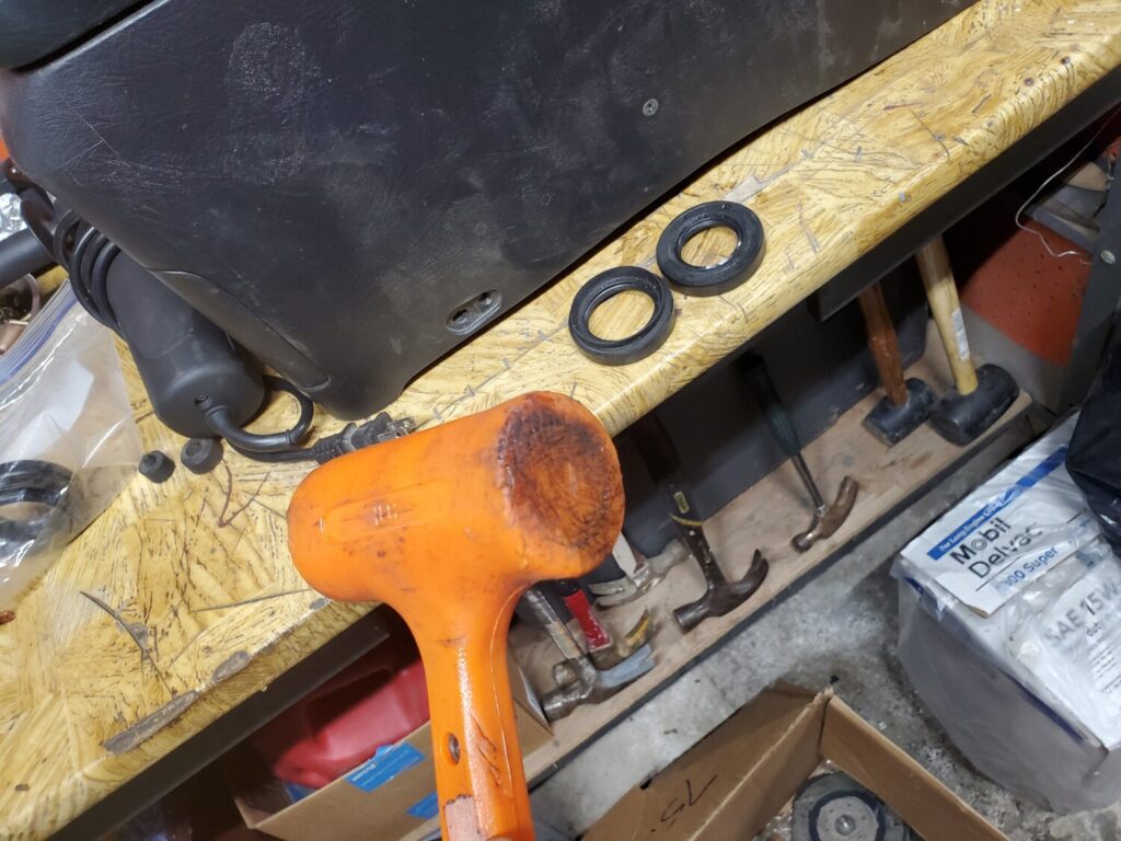
OEM Driver Side Part Number: 38342-81X00 Alternate Non-OEM Part Numbers: Timken / O’Reilly – 710118 Part Description: SEAL-OIL, Nissan Driver Side Output Shaft Seal / Differential Transmission Case Price: $8.00-$9.00
OEM Passenger Side: 38342-81X01 Alternate Non-OEM Part Numbers: Timken / O’Reilly – 710124 Part Description: SEAL-OIL, Nissan Driver Side Output Shaft Seal / Differential Clutch Housing Price: $8.00-$9.00
This fixed the infamous gear slamming issue after upgrading to the upgrade Level 10 valve body.
Reference Info:
The Nissan Maxima-Quest has become well known as a fine automobile. Unfortunately, the transmission continues to be a problem.
Even when overhauled, the same factory parts are installed resulting in the same problems. LEVEL 10 has developed a series of valve body components and modifications that will correct the hard shifts, gear slams, erratic shift points, and transmission failures. The best part of our modifications is there is no need for a complete transmission overhaul saving thousands of dollars.
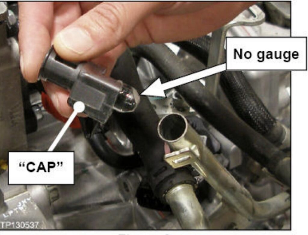
The 2016+ 8thgen Nissan Maxima does not come with a dipstick to fluid levels, unlike other generations. All new CVT transmissions from 2013-up are equipped with locking dipstick caps but no dipstick, with some Sentras and Versas being the exception to the rule. This was done to prevent the layman from screwing with fluid, etc.
Nissan service manual recommends changing CVT fluid when CVTF deterioration date is 210,000. The only way to check CVTF deterioration is through Consult-III+ scan tool. You can also do this with a CVT app on Android phones. The app is called CVTz50 and costs $5 bucks. You can read more about it here.
However, there is a way to check the fluid level. The service manual directs you to pump 2-3 quarts of NS3 into the overfill plug on the underside of the transmission. Not everyone has this fluid pump (ie. anyone that doesn’t work in a Nissan dealership.) The way around this is just to dump the fluid in through the dipstick tube with a funnel. It’s the quickest and easiest way around not having the fluid pump. The goal is to overfill the transmission by a quart or two. Next, you’ll have to hook up some kind of scan tool that can read transmission fluid temperature. The only way to monitor proper fluid level is by reading transmission fluid temp.
Hook up your scan tool, get the data monitor ready to view transmission fluid temp, and start the vehicle. Allow it to idle for ~10 seconds. While holding your foot on the brake, shift to reverse and hold it for ~5 seconds. Shift through all of the gears in this manner with your foot still on the brake to allow the fluid to work its way through the control valve assembly and all oil passages. This will ensure that the fluid in the pan is at the correct level. Shift back into park.
After you’ve done this, wait for the transmission to warm up to 95 degrees Fahrenheit. At this point, remove the 14mm overflow bolt on the bottom of the transmission. Fluid will begin to pour out, so be prepared. Monitor fluid temp while watching the CVT fluid flow from the overflow tube. Verify that the fluid slows to a fast “drip” before transmission temp reaches 113 degrees Fahrenheit. 95-113F is your temperature adjustment window. Once the fluid has slowed to a fast drip, install the overflow plug and you’re on your way!
In the event that the transmission was “too” overfilled and CVT fluid flow from overflow tube doesn’t slow before 113F, reinsert the overflow plug and allow the transmission to cool down. Lather, rinse, and repeat the above procedure.
Community Member Credit: Ezekiel-Adrenaline Persad
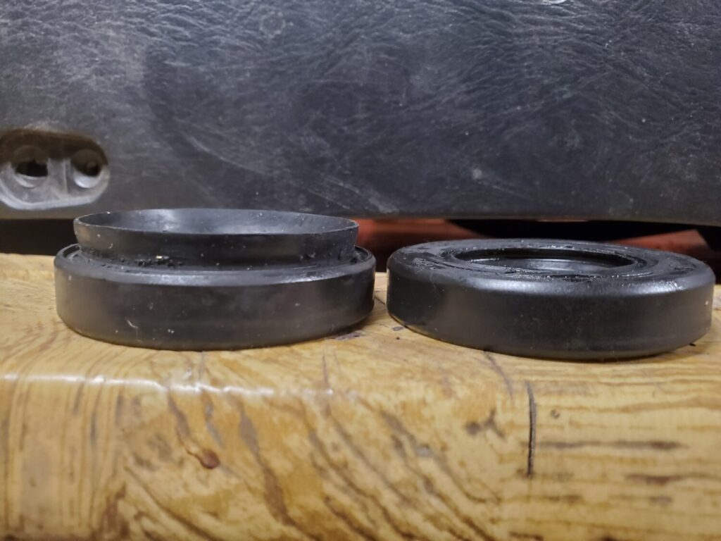
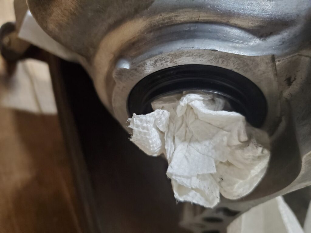
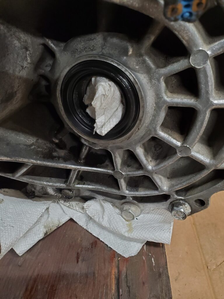
Just installed my diff seals for the axles. I don’t have a puller/installer kit so I’ve used a few ways to get these in there. Just sharing this if you don’t have the kit either. You can just use your old seal. Cut off the lip and you can hammer on it. Just place it over the new seal and send it no damage, easy, and free.
If you are looking to replace the Axles on your 2009-2015 7thgen Maxima, the A1 Cardone brand is a very good option and alternative to OEM. All owners that have installed A1 Cardone axles confirmed they DO NOT have any vibrations when driving at highway speeds. In fact, many couldn’t tell the difference between OEM.
Order Link:https://www.ebay.com/itm/303897376210(A fellow member confirmed these are Cardone) Additional Note: If you are in Canada, you can order Cardone Axles from partsavatar.ca Price: $319.41 Shipped (Includes both Driver and Passenger Side Axles)
The first thing u wanna do is remove your intake to get some room
Then u need to hook a rubber hose to the bleeder valve on the slave and put the other end in a bottle to catch brake fluid.
Go ahead and open that bleeder 10mm take the cap of the master cylinder reservoir and let it drain out crack the upper bleeder open 12mm to speed up the process.
Then you wanna remove the slave cylinder (2 14mm bolts). You could probably leave it on to remove the old hose from it but it seems easier to remove the whole slave if you have a strut bar remove the driver side (3 14mm nuts) for room.
Once you get that out of the way go ahead and remove the 12mm bolt on the slave to remove the old hose then move up to the master cylinder.
Remove the old hard-line from the master cylinder 10mm. It’s tight right there but I managed it then you can hook the new ss line to the master cylinder mine was an 11mm nut yours may differ.
Then route the line where u want it and install the other end to the slave cylinder.
Once u do that you can do one of two things leave the old clutch lines on the car or remove them. I took mine out looks cleaner. I took some pics but remove them from the car is pretty easy here are the pics disconnect this
Remove the 2 10mm bolts here
There is a junction box right under the brake master cylinder where all this junk meets just unbolt and remove.
Now you need to bleed the line once that’s done enjoy a clutch line u shouldn’t need to replace.
Now let me say this I can deff feel a difference. wife drove it and says that the clutch pedal feels a lot tighter and more responsive best 25 bucks I spent. I recommend this mod to anyone with a 5 speed.
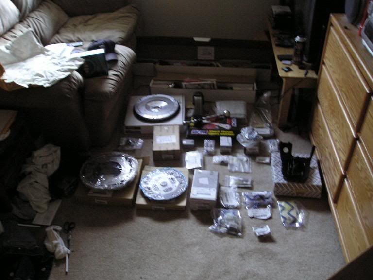
I took my time and saved a bunch of cash for a host goodies. Best ball park guess (includes shipping) $3500…
This included a lot of new stuff:
Just about the only thing that were used are the shift and control rods, the clutch and brake pedals, and a couple of the hard clutch lines. With the rods and pedals, I took them to my grinder and removed all the rust and them repainted them with rust proof stuff.
Parts List:
Lsd Manual Tranny- 320B0-40U77
Clutch Slave Cylinder- Cant Find Invoice
Clutch Master Cylinder- Cant Find Invoice
Manual Tranny Motor Mount- 11220-40U12
5th Gen Clutch Disk- 30100-2Y904
5th Gen Clutch Cover- 30210-89F00
Manual Flywheel Bolts- 12315-77A00
Clutch Cover Bolts- 30223-07S00
Shift Support Rod Bolt- 08121-0252F
Clutch Cover Bolt Washers- 30240-07S00
Slave Cylinder Bolts- 08121-02528
Manual Motor Mount Bolts- 01125-03291
Breather Tube for Manual Tranny- Cant Find Invoice
Shift Rod Support Bushing- 34560-70N00
Transaxle Hole Cover Plate Bolt- 74965-0E510
Return Spring- 34573-40U00
Manual Shifter Trim (Wood W/ Black Boot)-96935-40U10
Ae Shift Knob- 32865-4Y910
Ae Pedal Covers (Clutch and Brake Are the Same)- 46431-AB000
First, I removed the seat (only 4 bolts and a couple of connectors), the steering wheel trim, lower dash panel and the metal bracket behind it, the trim around the gauge cluster and pulled the cluster out (but left it connected), and the 4 nuts that support the steering wheel up. I used a jsck stand to support the wheel so that way it would not be just hanging there bottoming out and possibly causing some damge.
Now with all this stuff out of the way I now had enough room to remove the auto brake pedal/bracket. In order to do this I also had to remove the left steering wheel support bracket which is held in place by 3 nuts, and 2 of them require access through the cluster area which is why I removed it. With that out of the way, the brake pedal was only 4 nuts and a couple of connectors (but the 4 nuts can be a b!tch to get at).
I now had enough room to drill through the fire wall for the clutch master cylinder. I bought a right angle adapter for $35 from home depot (drilling in this tight of an area would have been IMPOSSIBLE with out it and I dont know how the other guys could have done it).
I also bought a STEP bit for $10 from home depot (I dont know why the hal write up called it a ‘tree’ bit). If you are thinking about just using a 3/8 bit (the size of the two holes for the studs that come from the clutch pedal bracket through the fire wall), forget it!! I tried to do this but the bit is too long, even with the right angle adapter. You need the step bit which gets progressively bigger as you go down the bit.
For the hole for the mater cylinder I used a 1-1/2 hole saw bit (once again, I dont know why the hal called a cylinder bit). This is the exact size for the master cylinder.
With all this, I drilled my holes (sorry I for got to take pics), and mounted the cluch pedal and the master cylinder. I know the master looks off center, but the holes lined up perfectly from the inside and the pedal bracket mounted up to the other factory bolt holes (that were previously unused) perfectly as well. This makes me think that the insulation in the engine bay is what is off (for some reason or another). It is moot point regardless.
Finally, I put the brake pedal in a long with the left steering wheel support bracket (I dont know why the hal threw his away, with out it your steering wheel is only half way supported), and put everything back together. The clutch pedal is NOT attached to the master cylinder in these pics (I have a new one on order), and this is why the clutch pedal sticks out more than it should.
Fidanza flywheel, 5th gen clutch, clutch master cylinder, clutch slave cylinder, ss clutch line from the GD, Raxles axles, AE clutch/brake/gas pedals, B&M short throw shifter, AE shift knob, shift support rod mount, manual tranny mount, plate bolt with transaxle hole cover, shift console trim piece with boot, a lot of misc. bolts and nuts, and of course a brand new LSD 5spd tranny.
Here is all the auto junk I ripped outta there. This includes all the little bullsh!t cables and brackets. I even removed the key interlock cable completely instead of just taping it into position like Hal did in his write up.
This was the only connector I ended up having to cut. It is the connector that went to the auto shift lever. I couldnt get it undone because the prvious owner had spilt soda down in there and it solidified the connector into one sh!t mess. I had to cut it.
While I was in there, I decided to replace the rear main… As you can see I had the slightest seep.
I rvt’d the hell outta the thing so it should not be a problem for a really long time…
Here is the signal plate on the auto drive plate. As you can see, the signal plate is not even shaped right to work with a manual flywheel. Not to mention it is riveted on. This delayed my project as I had to buy a used flywheel, so I could get the signal plate off of it for my Fidanza.
Here is the Fidanza with the signal plate on it.
Gotta love how there is already a factory hole… Only if Nissan would have done this for the firewall.
Here are the shift rods… Sorry this was the best pic I could get, because there is not a lot of room under the car.
Here is the car with everything ripped out.
Here are pics of the pedal install. I did this back in May while I collected more parts. I just continued to drive around auto with manual pedals.
Here is the tranny adaptor for my 3 ton jack. This thing is great. It gives plenty of room to rest the tranny on and it has slots so you can strap it down. It also can pivot and turn so you can mount the tranny with ease… Best $40 Ive spent.
Here is the Fidanza flywheel mounted.
Here is the 5th gen clutch.
Here are the Raxles axles. These things are top notch… The best looking axles I have ever seen. There even filled with amsoil grease.
Here is the B&M STS topped of with an AE shift knob. The look is proper… The way the shifter should have come from the fatory, instead of the ugly @ss flagpole.
Here is a shot of the ss clutch line.
WOW… Look at all the extra room now that the auto is gone.
About 6 months ago I received the death code P1778 (stepper motor) in my 2008 Altima. I searched far and wide, low and high, only to be told 2 things… you need a new transmission, or you need a new valve body. Since I didn’t have $2500 for a new trans, let alone $800 for the valve body I decided to look into this a little further. watched a YouTube video the only one I could find was a Nissan armada, but thought what the hell. I drained the fluid, dropped the pan, yanked out the valve body, and found that little bastard that gave me such trouble.
Now with part in hand I went to my local parts store, and told we don’t sell that part, its not even in our system… went to the dealership, told the same thing and was told I needed to buy a new transmission as they are not “serviceable” funny but I had the part in hand, how can it be not serviceable?
Lastly I took a gamble, I went to eBay, ordered a stepper motor. 20k miles later, still no code, no whine, and no lock up.
Part Number: 203452A Description: JF011E RE0F10E F1CJA Transmission CVT Stepper Motor For SENTRAN Nissan Dodge Refurbished Price: $30-$40
Here is how I saved thousands and bought a $35 part.
Drain fluid.
Drop pan (clean with brake cleaner)
Remove the 3 bolts holding filter. (clean with brake cleaner while your at it)
Remove the valve body about 11 bolts
Remove the stepper motor from the top of the valve body (the side you can’t see with the pan off) 2 bolts
Take a piece of dental floss about a foot long and hold the spring loaded arm back against the stepper motor and return the valve body back to the transmission.
After you have a few bolts in place remove the floss before you tighten all the way.
Reconnect trans filter and bolt back into place.
Rejoin the fluid pan to the transmission and replace with quality CVT fluid. Amsoil makes a great product.
I hope this helps and if you have questions please feel free to ask.
Video How-to (Many thanks to Budget Drift for this)
Ok guys after spending a lot of time and money last year I ended up using an automatic shifter dubbed shift-fast for my automatic transmission.. It is just some relays connected to a RPM switch (Emanage\UTEC\MSD). It works fine, it allows me to shift at any RPM I desire automatically which is great for the track. However it doesn’t control the converter lockup and I have to use the exact same shift RPM for each gear. The trans takes longer to shift from 2-3 than from 1-2 so the RPM is higher for the 2-3 shift, not exactly what I want. I was trying to come up with another way while watching the snow fall and although using 2 window switches would solve part of the problem its just more wiring and relays. Grey99 has also spent a lot of time working on the automatic shift-fast and has his own version working quite well.
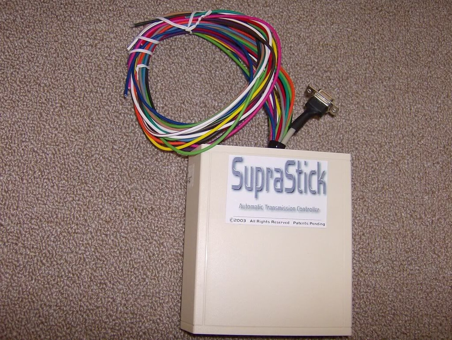
I decided to do some searching to see if anyone else had come up with an easier solution. After a few hours of searching I ran across a device made for the automatic Supra that does it all. Suprastick V4. Individual shift points for each gear, torque converter control for each gear, 2 maps (one for race one for normal), manual shift mode using paddles or switches, shift light, automatic protection from downshifting. It is a complete standalone TCU programmable via a PC. I have been in contact with the President and Chief Design Engineer Garrett Rowe who assures me he can easily change the code so it will work with the Maxima shift pattern.
The Suprastick manual can be downloaded here: SSv4.6 – Manual
I checked the G20 FSM and your trans in the same number of solenoids and same shift pattern as the Maxima/Altima so this will work.
Ok here goes. Does the SupraStick work? Yes, exactly as advertised. It comes packaged like this.
There are a number of programing screens to set it up but this is the most important one. There are 2 maps for auto shifting one for track and one for street or whatever. Just insert the speed you want it to shift at with the applicable throttle opening and bingo it does it. I have 2 switches one to select map 1 or 2 and another to select manual or auto shifting. I use the cruise control buttons for the manual up down shifts and it works great. One of the options is to set an RPM limit for downshifts, whatever you set this RPM for the trans will not downshift if it is exceeded to save your trans.
Does it work at the track? I waited until today to post this. There were around 24 cars in the field and I managed to win it all. Not too bad for an old guy that was paralyzed from the neck down 8 months ago. Youth and skill can be overcome by old age and treachery every time.
This is a pic of the display which is available for approx $35 to show mode, gear, throttle opening, speed and rpm.
This mod forces the transmission to shift at FULL Line Pressure at all times the switch is on. A WOT (Wide Open Throttle) switch is best suited for this purpose because the part throttle shifts are extremely harsh and could damage the transmission.
The drop resistor mod disconnects the dropping resistor in the transmission control circuit. This forces the transmission to run a maximum line pressure. This makes the shifts VERY hard. Even an otherwise stock car will chirp the tires on the 1-2 shift with this mod.
The downside is that part-throttle shifts are very jerky. The solution is to wire a Wide Open Throttle (WOT) switch that disconnects the resistor only at full throttle.
Reference Info:
The line pressure is varied according to throttle opening, RPM etc so that the more power you put down the more pressure is produced so that theoretically the shift time remains the same.
The more HP you put out the slower the trans will shift if you don’t increase the line pressure, so they have designed it to be suitable for 95% of the driving public.
What I am trying to do is have maximum line pressure at WOT ONLY, I like the way it shifts under normal operation, thats why I don’t have a VB mod. Maximum line pressure gives the fastest shift possible and saves the clutches from burning unecessarily. However I don’t want maximum line pressure at part throttle as the shifts are very jerky because the engine is only putting out very little HP.
The stock design does not put out maximum line pressure at WOT and the Drop Resistor Mod does.”
Installation Pics
Ok here is where the drop resistor is located. Front side of the drivers side strut tower.
There is a connector with two wires attached to the resistor. The electrical drawing of the drop resistor looks like this. You must cut one of the wires, doesn’t matter which one but cut it at least 2 or 3 inches from the connector so you have room to strip and connect to it.
Strip a small section on either end of the wire you just cut and attach a wire to each end by soldering or use a connector. Run the two wires to a switch. Either a WOT micro switch (preferably) as per the picture or a manual switch.
I have a small L bracket I made that attaches it to the intake manifold bolt closest to the throttle body.
Keep adjusting the switch position until the throttle hits it just before or when it hits the WOT position. It is imperative that this switch be a Normally Closed (NC) switch so the circuit is always made until you hit WOT at which point it opens and effectively disconnects the drop resistor from the circuit.
You can do the same thing by running the two wires to the cabin and hooking to manual switch (5 amp rating or higher) but I much prefer the WOT switch because you never have to worry about turning it on or off. You have enough to think about when racing without another stupid switch to turn on and off.
The micro switch I use is rated at 10 amps and I got it from an appliance shop where it is used in a microwave.
Most switches of this type are Normally Open (NO) and this will NOT work.


")


")
")
")


")