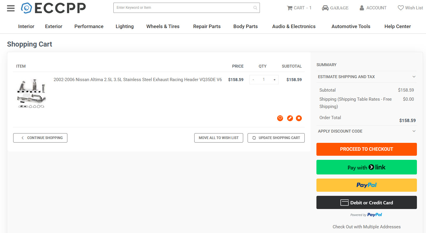
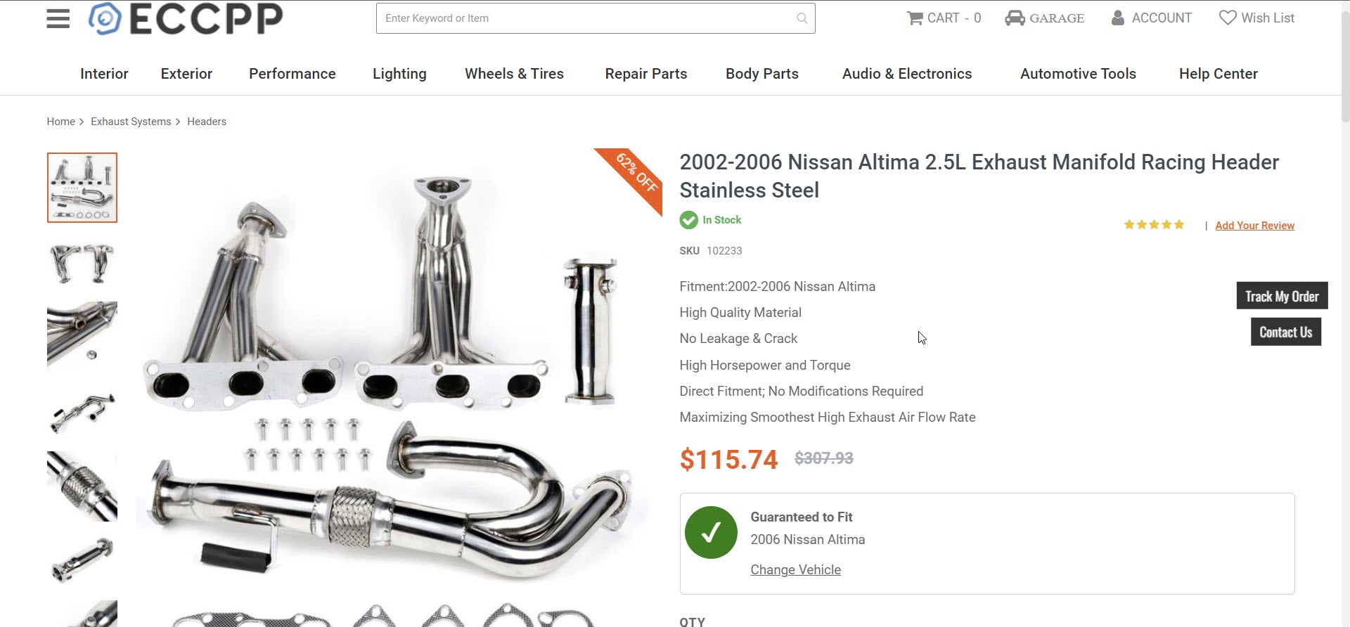
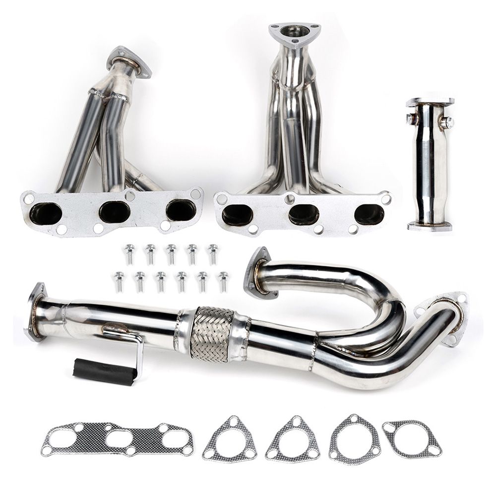
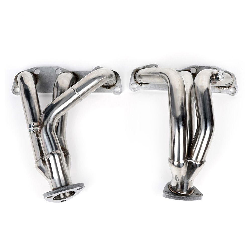
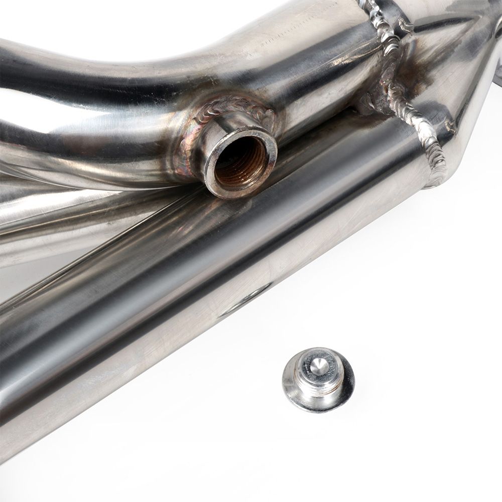
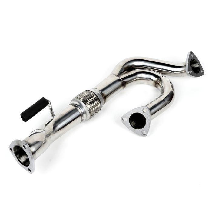
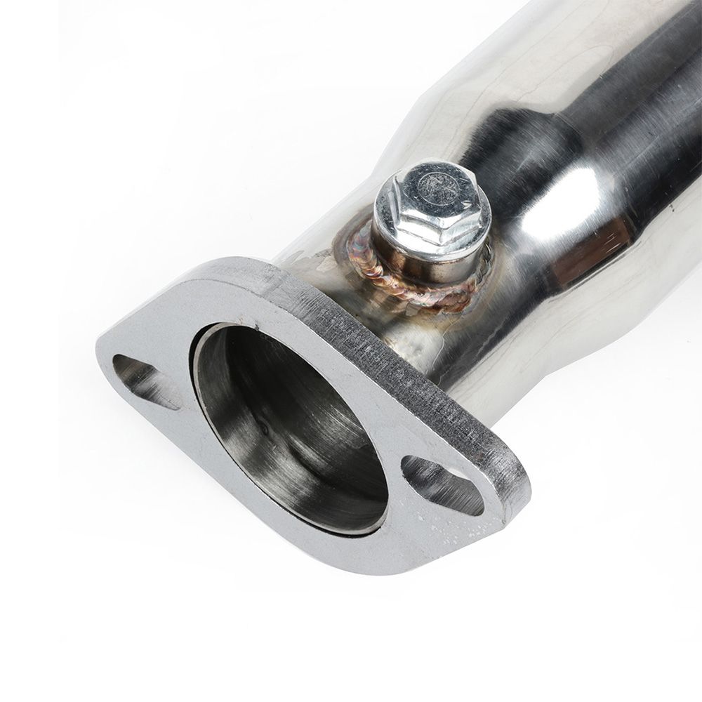
Description: 2002-2006 Nissan Altima 2.5L Exhaust Manifold Racing Header Stainless Steel Part Number: 102233 Price: $158.59 (Shipped)
Important Note:
These show 2.5L vs 3.5L. Josh confirmed they are for the 3.5L and he installed on his Maxima. He is local to them.
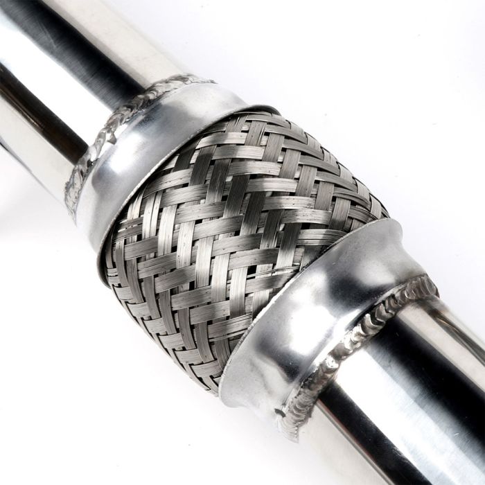
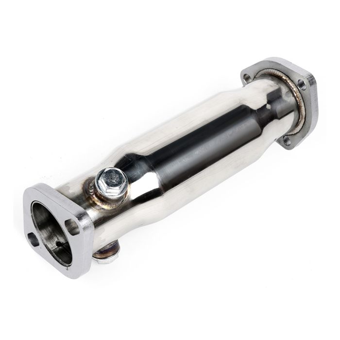
As you’re aware these require modification of y-pipe for perfect fitment. Please research it. This has always been known with the Altima VQ35DE headers. They are NOT plug-n-play. But for the price, they are very well worth it. These also come with a downpipe so it makes an even more awesome price.
A few maxima members have already ordered and confirmed this is a legit shop. They’ve received their ordered with no issues.
This article shows how to swap a 2007+ Altima 3.5L VQ35 engine, or 2009+ Maxima 3.5L engine into older Nissan Maxima’s. Including the 2002-2006 Altima (3.5L) and 2002-2008 Maxima’s. This motor swap is referred to as the 2nd Generation (Gen2/Gen3) VQ35DE swap.
NISformance Swap Kit
This kit allows you to install a 2nd generation or 3rd generation VQ35DE engine into a 2002-2008 Maxima or 2002-2006 Altima (3.5 V6)
The NISformance 2nd Generation VQ35DE swap kit consist of four main components. (2) Cam sensor signal inverters, a plug and play throttle body adapter harness, a belt tensioner bracket, and an alternator bracket. Each component and its intended use is detailed below.
Camshaft sensor signal inverters – Allow the stock harness to be attached to a newer 2nd generation motor and intercept the camshaft signal wires. This is an essential part of the swap kit and has been designed with ease of install in mind. Each inverter comes with a camshaft sensor plug attached. Wiring necessary consist of three wires. Ground, Power, and Signal. These new inverters are single channel. One inverter is required for each camshaft position sensor.
Throttle body adapter harness – Necessary in order to utilize the 70 or 75 millimeter throttle body that is equipped on 2nd generation motors.
Belt tensioner and alternator brackets – Needed in order to use stock alternator and belt tensioner. Zinc coated for high corrosion resistance and added clean look.
VQ35DE Engine
There are three generations of the front wheel drive VQ35DE engine.
The first generation VQ35DE was used by Nissan in many front wheel drive applications. Ranging from the Maxima to the Quest minivan.
Second generation engines were used in the 2009+ Maxima , and 2007+ 3.5L Altima as well as a few other front wheel drive applications as before. The second generation VQ35DE engine is equipped with “HR” heads allowing for increased air flow and improved performance. Oil consumption and other flaws commonly found in first generation motors have also been addressed.
There are also two variations of the 2nd Gen VQ35DE engine. A Maxima engine is equipped with EVT ( Exhaust Valve Timing ) and has a slightly higher compression ratio along with larger intake manifold and throttle body (75mm). The Altima engine has a slightly lower compression ratio, and is not equipped with EVT. The intake manifold and throttle body (70mm) are also a bit smaller.
There is now a third generation of the front wheel drive VQ35DE. This engine is found mostly in the 2016+ Nissan Maxima. This engine can be used for this swap, with the only difference being the TB pin out. We offer the correct TB adapter harness for this newer TB as an option for our swap kit.
There are a few things to keep in mind before beginning your swap:
It’s easier to do this swap if you have a 3.5 DE motor laying around, especially if you just pulled it out of the car. You will need to take some things off of the old motor to use on the HR. Without this, there are a few parts that you will have to purchase in order to complete the swap.
Keep in mind, you are swapping the “long block” with intake manifold only. You will need to re use a lot of your existing accessories or parts specific to your car. This also includes wiring and harnesses, sub harnesses ect..
Picture below is what your prepped “2nd Gen” or “3rd Gen” engine should look like prior to going into your car.
There are some specific tools needed: An ‘E8’ torx socket, 5/16 Allen key, Loctite
Stripping the motor
Depending on where your motor came from, there may be a lot of ‘extra’ pieces still attached to it. Some of these will just get in your way while you prep your motor, some can’t be used for this swap.
Remove all accessories, which includes the alternator, power steering pump.
Remove any harnesses and brackets that are still connected to the motor.
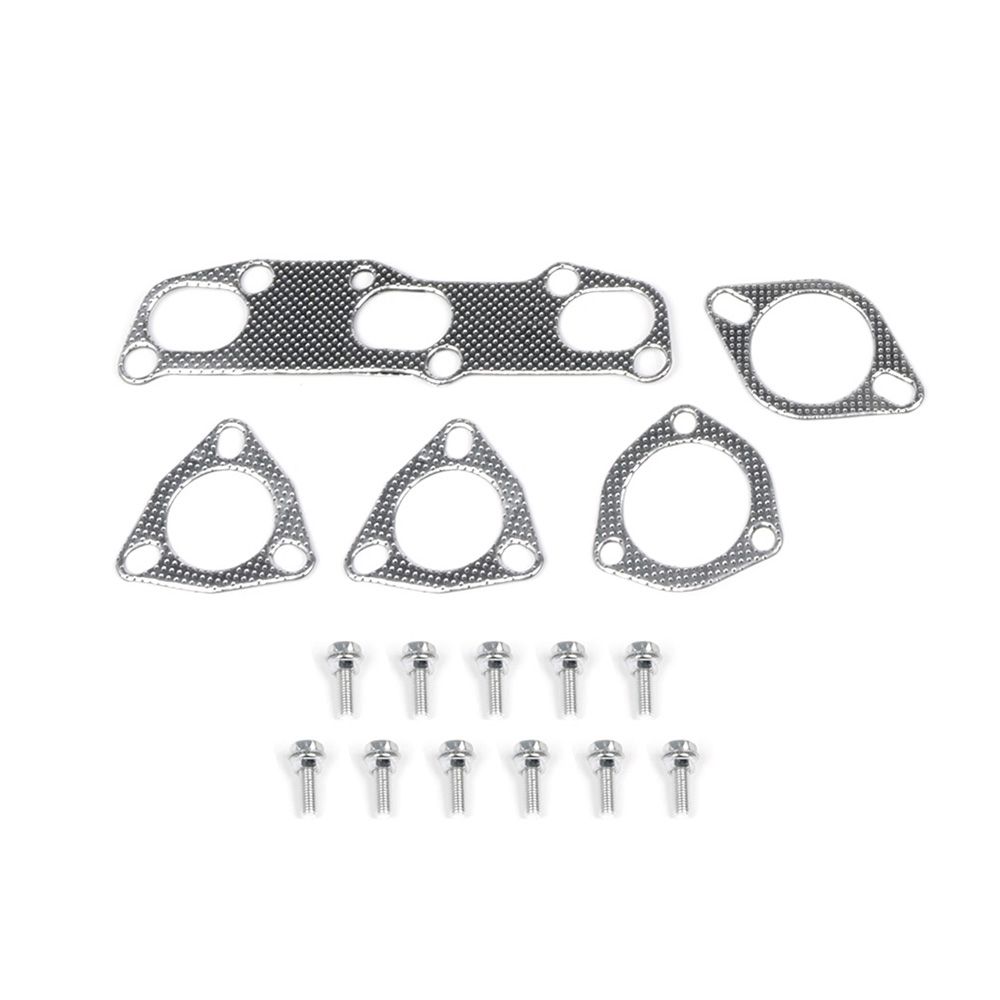
Remove upper intake manifold (removing lower manifold is not necessary, but sometimes desirable. If removed, a new gasket should be used to reinstall).
Remove oil temperature sender:
Remove idler pulley/tensioner ‘spacer’ (seen below in red): ** The injector rail may also be removed, but that isn’t necessary.
Modifying the Motor
Some parts of the motor will need to be cut somehow (tools, methods and results will vary) to allow for proper fitment and function once it’s reinstalled.
** Because of some concerns about the integrity of the stock oil gallery gasket, we at NISformance strongly recommend replacing it in this step. **
When changing the oil gallery gasket, this is a good time to grind away the center portion of the power steering bracket before reassembling the front of the motor.
Grind/cut away the center portion of the power steering bracket. This requires some aggressive cutting, but also needs some attention to detail (cutting too DEEPLY can weaken the integrity of the timing cover. Cutting too WIDE can weaken the remaining brackets that will be needed to hold the alternator):
Grind/cut away a portion of the metal where the idler pulley/tensioner spacer was:
Remove exhaust manifold studs at the rear most exhaust port (close to the trans). This requires an ‘E8‘ torx socket:
Clean out the threads in the opposite holes using a ‘10×1.25‘ tap.
Replace the removed studs into the newly cleaned holes:
Remove lower oil pan.
Remove upper oil pan.
Use the oil pan from a 3.5 DE motor…but remove the windage tray. Add your o-rings and seals, and install upper oil pan onto the HR motor.
Remove the HR water pump access cover, and replace it with the one from the DE motor
Alternator bracket
Belt tensioner bracket
Adjusting the Cam Signal Trigger Wheel
*Please note that we now offer a completely bolt on trigger wheel that eliminates the need to modify your stock trigger wheels*
If you choose to modify your stock trigger wheels, please note that this is a VERY important step and it must be done very carefully for your car to run properly. You have to be extremely accurate.
Apart from the wiring, adjusting the signal wheel is the most detailed work you need to do on the swap. It is important to be very accurate when cutting or grinding, and it’s also extremely important to assemble everything correctly at the end of this step. Pay close attention to the pictures and make sure that your work looks EXACTLY the same!
*You will need to modify your 5/16 Allen key by cutting the arm down so that it is approximately 3/8″ long. This is your ‘special tool’ that you will need to use in this part of the swap.
Open one of the valve covers.
Using the ‘special tool’, loosen the signal wheel lock nut and remove the signal wheel from the intake cam:
Completely remove the inner nubs from the signal wheel without damaging the rest of the inner surface:
Add Loctite to the flat inner surface of the signal wheel:
Reconnect the modified signal wheel to the intake cam…be sure to place it at the proper angle (as shown below) and resecure the lock nut:
Close and bolt down the valve cover
Open the other valve cover, and repeat these same steps.
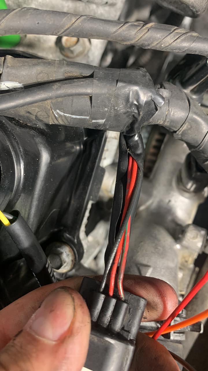
V2 Cam Sensor Signal Inverter Wiring
V2 inverters are single channel. One inverter is required for each camshaft position sensor.
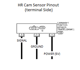
Wiring for cam sensor signal inverter
Red wire – 12 volt power supply ( power going into the board )
Black wire – Ground
Orange wire – Signal out ( connects to existing wire on ecu side )
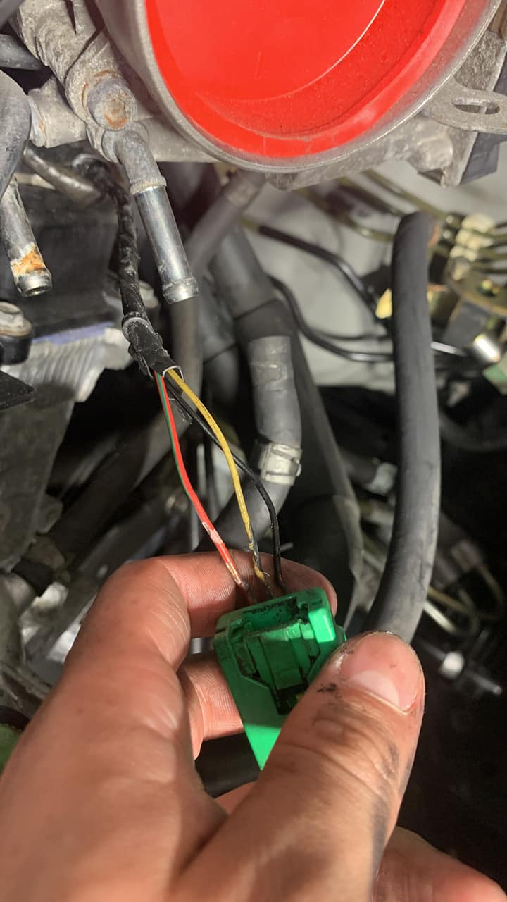
Picture below demonstrates the older style DE cam sensor plug that is cut off when wiring in inverter with required wiring
V1 Cam Sensor Signal Inverter Wiring
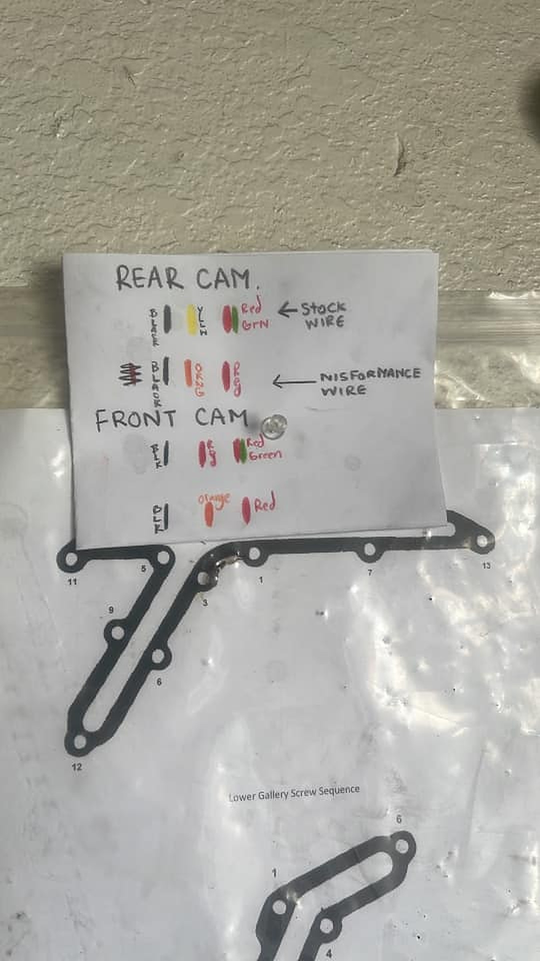
The wiring harness in your car needs to be connected to the newer motor, and it’s not just a ‘plug-and-play’ situation. These diagrams show you the changes that need to be made to make your DE harness control your HR motor:
** THESE WIRE CONNECTIONS ARE CRITICAL. MAKE SURE THAT THEY ARE CONNECTED CORRECTLY (ACCORDING TO THE INSTRUCTIONS), AND SECURELY. TWISTING THEM TOGETHER IS NOT GOOD ENOUGH. **
The stock cam signal wire will be intercepted (cut) by the cam signal inverter supplied with the swap kit. There are six wires on the cam signal inverter…here’s how you connect them:
the RED wire goes to a 5v source from your car’s harness (to supply power to the sensor)
the BLACK wire is ground
For Cam #1…cut the existing wire:
the YELLOW inverter wire connects to the existing wire on the CAM side
the ORANGE inverter wire connects to the existing wire on the ECU side
For Cam #2…cut the existing wire:
the BLUE inverter wire connects to the existing wire on the CAM side
the GREEN inverter wire connects to the existing wire on the ECU side
Member Credit: Hassan A. / Ethan G. Download PDF:link
This guide covers the installation of an 8th-generation (2016–2020) Nissan Maxima steering wheel onto a 5th-generation (2002–2003) Maxima. The setup enables full button functionality and backlighting. The steering wheel is from a 2019 Maxima (with audio and cruise control buttons, non-adaptive cruise).
Assumptions:
You’re willing to relocate the drive computer button elsewhere.
You don’t require the drive computer display to function.
You have an aftermarket stereo with a working steering wheel control interface (e.g., PAC SWI-RC module).
Airbag Wiring
This is the custom harness for airbag connections using yellow connectors. This section focuses on splicing and matching the correct airbag plug types from the 8th-gen wheel to the 5th-gen airbag system.
Steering Side Wiring for Lights and Buttons
Button Resistance Mapping (8th Gen Wheel)
There are 5 unique resistance values for 10 functions, so the wiring must be combined into a single signal line by adding a 1 kΩ resistor to one wire when merging signal lines.
Connector Pinouts
5th Gen Connector (Vehicle side)
Pins 13–20 handle functions like Mode, Volume, Cruise, Drive Computer, and Horn.
8th Gen Connector (Steering wheel side)
Adds an extra pin for illumination (12 V for button lights).
Pin Mapping Table (5th → 8th Gen)
5th Gen Pin
Function
8th Gen Pin
Function
13
Empty
13
Cruise Control (White)
14
Mode / Track Up (Orange)
14
V+, V−, Tel End, Display (Yellow)
15
Volume Down / Track Down (Blue)
15
Source, Up, Dn, Tel, Enter (Green)
16
Button Common (Yellow)
16
Cruise Control (Brown)
17
Cruise Control (Green)
17
Common wire for buttons (Blue)
18
Cruise Control (White)
18
Horn (Grey)
19
Drive Computer (Purple)
19
Ground (Black)
20
Horn (Red)
20
Light 12V (Red)
The 8th gen clock spring supports all buttons and illumination.
Re-Pin Order for 5th Gen Connector (Table 2)
Pin
Wire
Notes
13
—
Empty
14
Black
Ground
15
Yellow + Green (1 kΩ resistor added)
Signal
16
Blue
Common ground
17
Brown
Cruise
18
White
Cruise
19
Red
Lights
20
Grey
Horn
Diagram #1
Shows re-pinning layout and resistor placement:
Add 1 kΩ resistor between green and yellow signal lines.
Swap black and green wires as shown.
Connect Red → 12 V lights, Grey → horn, Blue → common ground.
Column Side Clock Spring Connector Modifications
To integrate lighting and drive computer trigger, modify 3 wires at the column-side plug:
a) Cut the red wire, solder its connector side to ground, and tap the car-side red wire into Blue/Yellow. b) Cut Green/Red wire, and connect its connector side to switched 12 V+ (from the Red/Blue wire near driver kick panel, used by headlight switch). c) Column-side Green/Red wire is the Drive Computer trigger — wire it to an external momentary switch if you want to retain trip computer function. d) Identify the correct radio control wire on your stereo harness; follow your interface module programming guide. e) Reprogram your PAC SWI-RC or similar interface for new button functions.
Diagram #2
Shows:
Splice Red ↔ Blue/Yellow.
Connect Green/Red → 12 V switched (Red/Blue at driver kick panel).
Ground the cut Red wire’s connector side.
(Optional) Wire Drive Computer trigger to an external button.
Final Result
2019 Maxima steering wheel mounted in a 5th-gen dashboard.
All illumination LEDs and button functions (audio, cruise, phone) work properly.
Year: 2003 Model: Maxima Color: Black Engine: Gen3 VQ35DE Transmission: 6-Speed Manual
Fully built and running setup with a BorgWarner SX300 66mm turbo. Tuned on E85 using a Haltech Elite 2500 ECU paired with an IC7 digital display for real-time data monitoring. Equipped with an Innovate SCG-1 boost controller and Altima 5-speed manual transmission.


")


")


 ** The injector rail may also be removed, but that isn’t necessary.


")


")


")


