Credit: Kirill Savin





Credit: Clutched_tombo
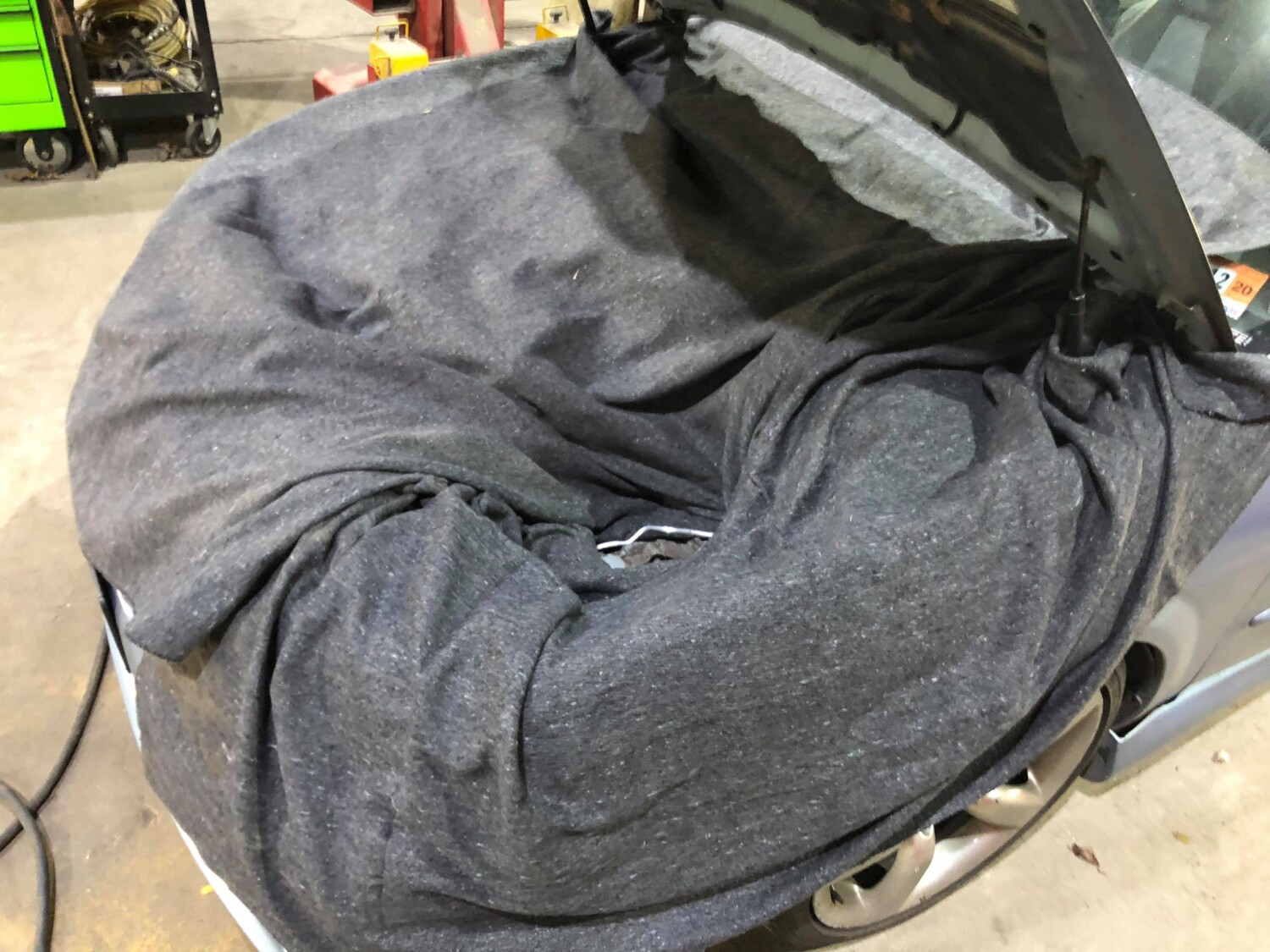
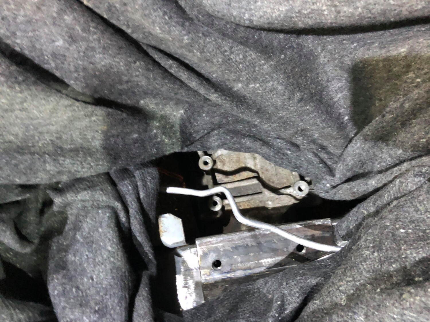
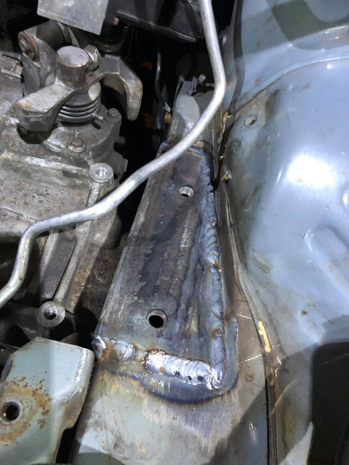
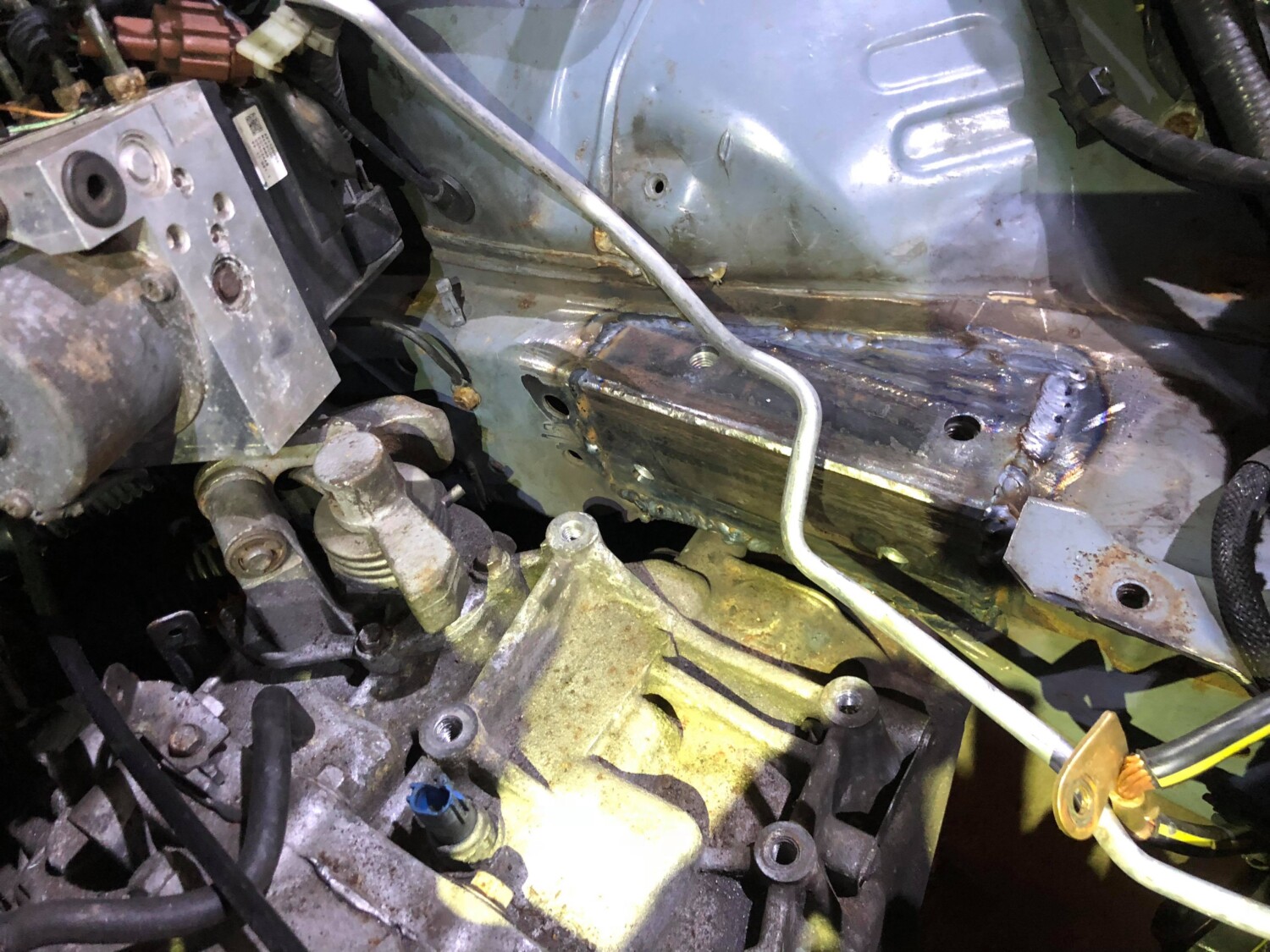
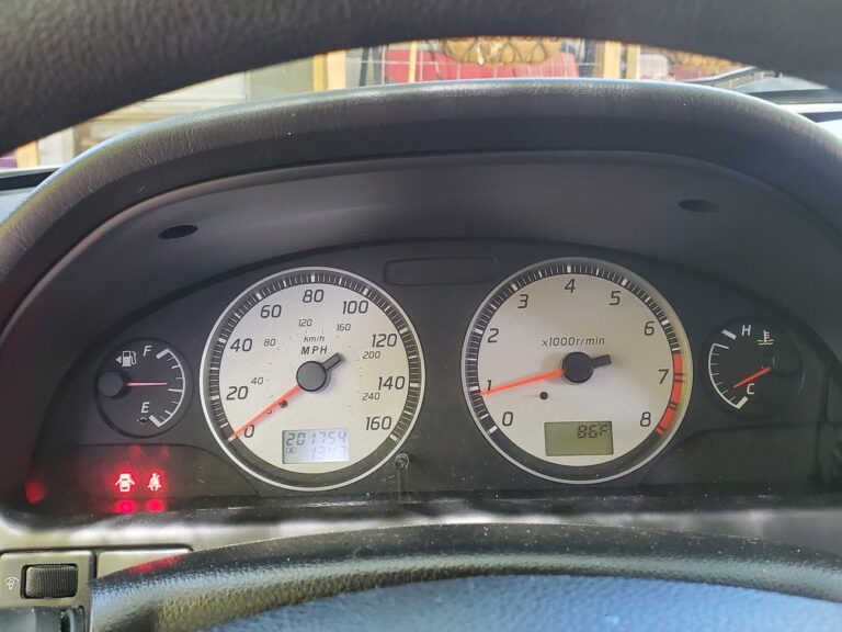
Hope this can help anyone that wants to use an aftermarket fuel gauge. May already be a write up on this but I couldn’t find it. I decided to go with aftermarket after not being able to find a cluster with one that actually works correctly.
Used one from Glowshift. Regardless of what gauge brand you use, results will be similar. After a few trials and error I got the new one working with no cel and gas lights on. I chose to mount the new gauge where the ashtray is. Didn’t take pics of how I wired power to it but I just used wire taps on the constant and switched ignition to the stereo.

Under the back seat I chose to just cut the green signal wire going to the fuel pump sending unit. With this wire not connected you will get a cel for high signal input. It uses a variable ground signal from the sending unit. You will also get the low gas warning light and dte will flash. I used a 47 ohm resistor and grounded the side going to the body harness and hooked the new gauge up to the side going to the pump. Ignore the butt connectors. This wasn’t the finished product. It was soldered after everything was working right.

If you ground the wire without the resistor, you will still get a CEL. After it’s all done with, my OEM gauge sits right above half and I have no CEL. You should be able to use any resistor between about 10 and 75 ohms. I opted for 47 OHM. Since it was in the middle of the resistance values of the sender. Last pic of where it sits with it all finished up. I’m happy with it.

Credit: Rene aka https://www.youtube.com/user/carsnwomen91
Member Credit: KZ 259
Disconnect the battery first.
At the bottom of the glove box, there are two black tabs that hold the bottom in place. remove these two tabs.

After remove the tabs, there will be 5-6 screws holding the frame of the glove box in. Remove the screws.


glovebox hanging, the frame is taken off

Gglovebox taken off, frame is off. If you are doing this, checking your in-cabin air filter is a good idea.
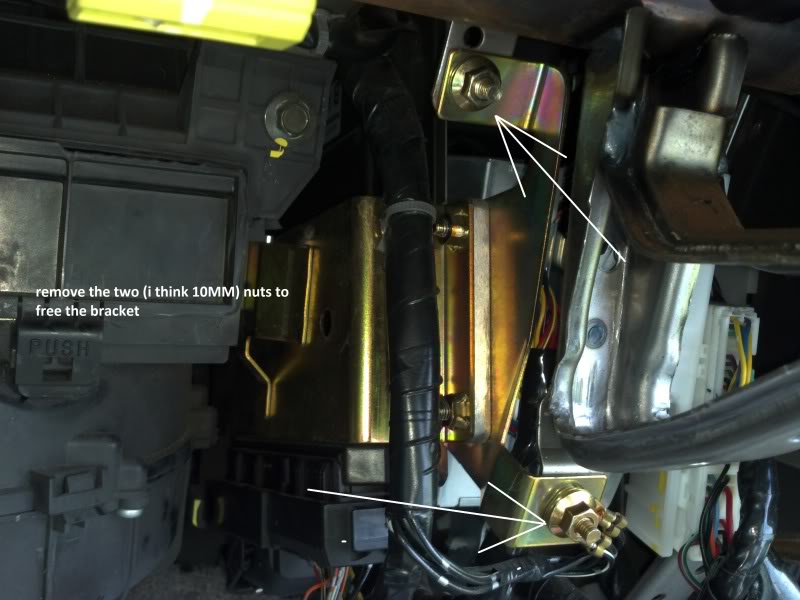
And there she is! the ECU, i mean. it is held inside that gold-looking bracket and you can see the connectors from below.


After completing the instructions in the picture, you’re ECU is officially disconnected from the car.
I know back years ago, Jet Performance would mod the ECU for you to make the car faster by mailing it out to them. Technosqaure does or did the same thing. when my friend use to own a 6thgen max, he shipped out his ECU to Jet Performance, and with an intake and a flashed ECU, he beat me by 2 car lengths. my car was in stock form back then. pretty interesting but if you any questions just ask!!
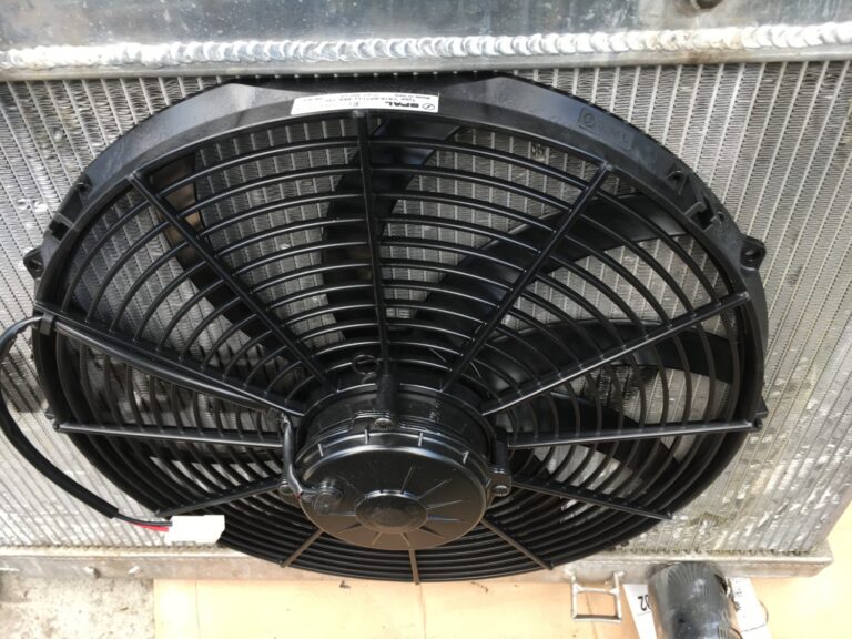
This post if for folks looking to install SPAL Fans into their Maxima. These are quality high-speed fans that are great for both N/A and Boosted Setups.
We designed the SPAL fan wiring harness to enable the simplest installation of our performance fans. It is compatible with all types of vehicles and can be installed on positive or negative ground vehicles with no modifications
When installing electric cooling fans, it is important to cover as much surface area as possible. Mount the fan as high up on the core as possible. Attach the fan to the small area around the core of the radiator where there is a metal lip that is approximately 1/4″ to 3/8″. This will allow mounting of the fan(s) without compromising the core of the radiator.
Mount the relay in a secure place in the engine compartment away from heat sources. Once this is completed, connect the wires per the diagram and notes below.
Installing the Thermostat Switch:
The sensor has 3/8″ pipe thread. The thermostat supplied with the kit is an OE type that is designed to mount in the cylinder head of the engine. However, any mounting in water jacket is suitable. The 195FH sending unit comes on at 195 degrees and off at 175 degrees. The 185FH module turns on at 185 degrees and off at 165 degrees. The modules will work on the majority of applications. If a different size adapter is needed, the correct size thread adapter can be found at most automotive parts or hardware stores (1/2″ adapter included in the kit) . Do not use Teflon tape on the sensor it can cause poor electrical contact and incorrect temperature readings.


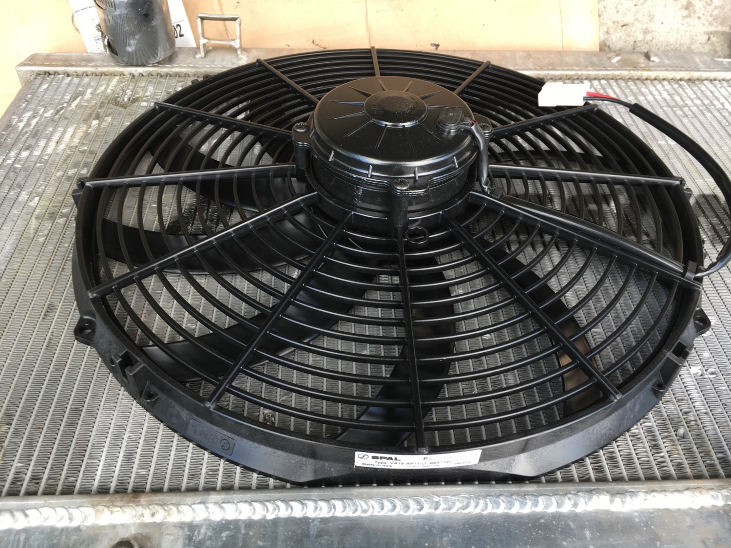


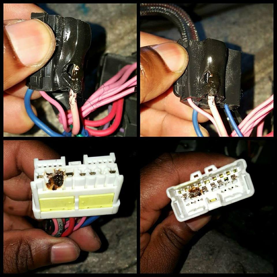
If you don’t use a good relay like the one above, this will happen (Photo Courtesy of Javon Bennet)
Member Credit: CXJ Performance
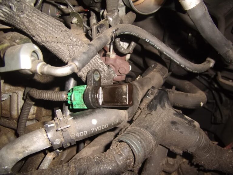
I went to start my car using the auto start and it stalled. I got the car checked and it threw code P0340 Camshaft Bank 1 Position Sensor Malfunction. Below is my guide to the repair.
Symptoms
DISCONNECT BATTERY FIRST!!!
If your stock remove your filter intake portion first using a flat head screwdriver.
 Disconnect your MAF sensor ( while your here this would be a good time to use MAF sensor cleaner as I did )
 Using pliers remove the vacuum hose carefully and remove the rest of the intake box and set it aside.
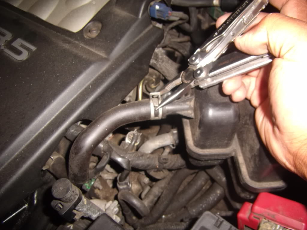
 Now move on the upper tube that’s connected to the intake manifold and using the flat head loosen that connection.
 Set aside that tubing as well
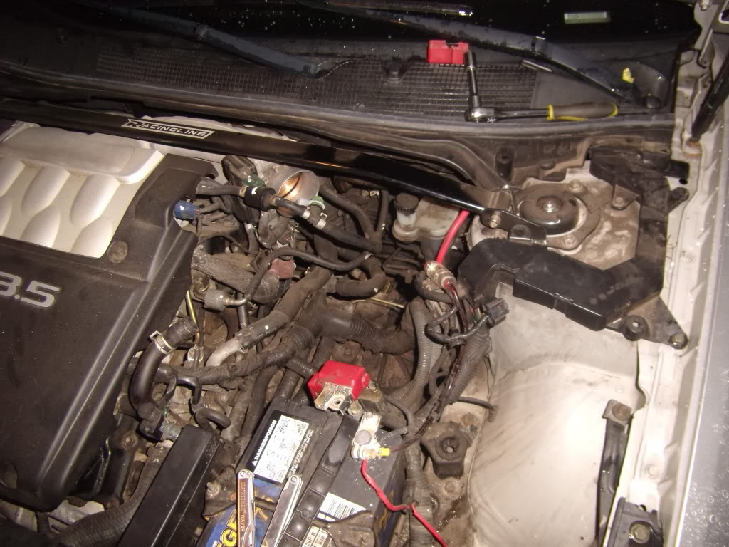 Now that you have the room you be able to access the bank sensors better, in this case, were going for Bank 1 which is the green clip located closer to the firewall but just at the base of camshaft near ignition coil 1 as well ( Bank 2 is closer towards the front almost 6 inches from Bank 1 in the direction facing the car bumper still with the same green clip.

 Using a 10mm socket and extension remove the bolt holding the sensor in place.
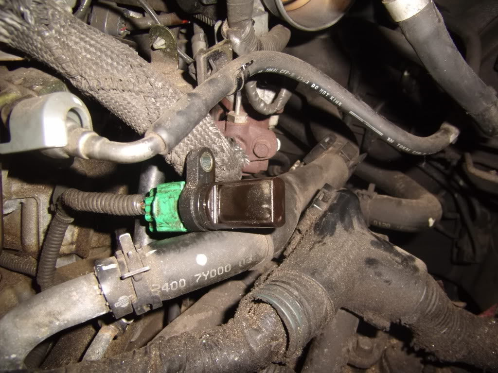
 There is also a small clip holding the sensor harness against a plate to remove this clip so you can manage the sensor better.
Now, this is the hardest part. the clip is a weird design intended to almost never let the sensor go. it involves you pushing up and then pulling down in order for you to release the sensor from the holder and its a pain in the ass to remove.
In case you get the sensor off replace with part # 23731-6J90B which is bank 1.
 Replace all parts in the order they were taken off. Clear your CEL and all set.

Often times this water pipe will rust and break. Especially in areas of snow where salt is put on the streets. Below is the part number you need for replacing it.
Part Number: 14053-JA13A
Price: $33.65


Member Credit: Sparky
This 1997 Nissan Maxima was towed in from another shop after unsuccessful repair attempts. I am not sure how many shops it has been to. Tried to crank vehicle, it spit and coughed and jumped and carried on but I managed to get it to fire a little by depessing the gas pedal to the floor {clear flood mode}.
I checked the plugs and they were black and fouled out and several showed signs of gas blowby at the insulator seal, so I installed a new set of plugs. cranked the engine and it ran. After a couple of minutes it had cleared up and was running good. Ran a few more minutes for good measure. Turned engine off and recranked. It cranked and ran fine. Did the other shops miss something this simple? I don’t know? Cranked it several times and no problems, time for a test drive. Backed the car out of the shop and took off on a test drive. Right, got 20 feet and it stalled and would not crank back up. Kind of figured it, plugs would be too easy.
Got the scanner out and checked codes P0325 and P0340 were stored. The P0325 code is for a knock sensor and will not cause the engine to not run, so I was going to concentrate on the P0340 code. The code P0340 is for a cam sensor error. Checked the cam sensor and it had been replaced.

I needed to check the continuity of the wires between the cam sensor and the ECM. The ECM is located under the center of the dash as shown below.
I removed the white plastic cover to have better access to the wiring.

I had to use an ohm meter hooked to both ends of the two wires. While the harness (shown below) was wiggled. Sure enough one of the two wires was broken. In doing this repair I had to try several things before I came up with a way to repair this vehicle in a cost effective way. The harness costs about two thousand dollars plus installation.

I clipped the two wires near the ECM harness connector. Then started to look for a way to run new wires. My first choice would be to attach new wires to the old, with splicing connectors and pull them through the harness, then splice at the other end. This would not work as the wires are glued into the grommet at the firewall. It would be virtually impossible for me to identify the two wires at the ECM so you will need to access that information from Mitchell 1. There is a link at the top right of this page.

My next choice was to try and run the new wires through, hopefully another grommet. The problem is the only other thing I could see was the a/c drain tube. Running new wires there did not seem like a good idea. To get a really good look the evaporator case needed to come out. Recovered the refrigerant and removed all of the interior mounting screws.


Problem, the evaporator case will not come out past the glove box support brace. A very close look and I determined that if I removed the metal brace. Then cut the plastic between the two screw holes on each side that the evaporator case would come out. When reassembling the two screws would hold the plastic pieces together. It appears to me that an engineer actually designed it to be cut, if the evaporator case needed to be removed.

The cut on the right side of the glove box opening.

At least now I can see where the wires go through the firewall. I felt around and decided that I could go through the original grommet. On the lower right side, as it is viewed in the pictures below.

I have a special tool for doing this procedure. The tool is similar to a screwdriver but it has hole running through it. Using the sharp end I pierced the grommet and ran the wire through the hole in the tool.

With the wire run through the hole in the tool and to the other side of the firewall, I pulled the tool back out over the remaining wire on the inside of the vehicle.


A close up look at the hole in the handle.

The sharp end of the tool that easily pierces the rubber grommet.

I purchased a special piece of shielded, twisted, pair wire cable from an aircraft supplier. The first thing that had to be done was to loosen the shielding and move it down the cable assembly enough to stagger the joints. I did have to split it length way also.

After prepping the cable, I connected it to the factory harness connector. I staggered the joints.

Heated the tubing and shrank it into place.

Twisted the remaining cable, around the repair.

Pulled the shielding back up and around the spliced wires, then used tape to hold it in place.

I repeated the process at the other end near the computer. I then taped and wire tied the new cable to the old harness. One thing that I learned through this whole experience is that if at all possible do not pull the harness out from under the dash. It is looped to the top of the ECM and is almost impossible to get it back into place. The reason I had pulled it out was so that I could pull the new wiring through the old harness and just attach it on both ends. The glue in the fire wall grommet prevented me from doing this, so in the end, there was no reason to pull the harness loose that far.

A closer look at where the wiring breaks inside the harness. My experience on this one also convinced me to not open the harness to actually see the damage. Way too hard to get it all back together that way. Just make sure the wiring is the problem with a meter and/or piggy back a new harness to the outside of the old harness and attach it at both ends.


Credit: pimpin02max
Alright…there seems to have been many many questions about the install of the newer OBX Headers/Y-pipe. So I have decided to do a small writeup on the installation of these headers/y-pipe. So below I have made a faq with some of my answers that should be right but if I am wrong on anything feel free to let me know…and like everything else, this is a guide to help you on your install and any questions you have, so if you screw something up it is not my fault
FAQ
1. Are these worth saving the extra money over the Cattman’s?
(Answer) If you are a do-it-yourself kind of person then yes definitely, the Cattman’s are an awesome product and have no fitment issues whatsoever (I have owned a set of Gen III’s) and the peace of mind is nice, but if you aren’t afraid to do some small modifying and saving around $500 sounds good then yes the OBX headers are for you.
2. Do these make decent power compared to the Cattman’s?
(Answer) The OBX Headers make just as much power as the Cattman’s. Depending on who you ask some will tell you they make more but I think that since the dyno’s differ I would say all around they make around the same power.
3. I have heard you have to extend the O2 sensors, is this all 4 or just the primaries?
(Answer) Alright, when I installed my headers all I had to extend was the primaries which are the O2 sensors in the collectors of the headers…now if you choose to plug up the secondary O2’s then you might have to extend them, I don’t know because I did not hook mine up.
4. Do you have to relocate the rear bung for the primary O2 sensor?
(Answer) Don’t know if you absolutely have to but I would 100%…it makes the install a lot easier and you won’t be so worried about it hitting the steering rack and whatnot. All you need to do is move the bung 90* to the right on the collector and your good to go, you could have a shop do this for you or for the DIY’r you could do it in your garage (like me…lol)
5. Will I throw a SES with these headers?
(Answer) Yes most likely, since you do not have any precats for the secondaries to monitor you will throw a code which is why it is useless to plug up the secondaries to begin with since they will still throw a code because there are no precats. The SES light thrown will not effect your performance at all because the primaries are the only O2’s that affect your A/F ratio. Now all you need is a dual output O2 simulator which you can get from here: http://www.02sim.com/ Some have reported not throwing a SES and most get one. When I installed my Cattman’s I threw one upon first startup, with the OBX’s I have been driving around for 1 1/2 months now without a simulator and have yet to throw a code, but that’s just mine.
6. Should I use the gaskets included with the headers or the OEM ones?
(Answer) Definitely use OEM multi-layer gaskets because the ones included like every other header kit are crap. Now if for whatever reason you have to use them then they are ok but plan on changing them down the road because they won’t last as long as your OEM ones.
7. Is there that much modifications to make these work?
(Answer) That depends on who your talking to. I didn’t think it was that bad. The only modifications I had to do was to move the rear bung 90* to the right, plug the 2 secondary holes in the y-pipe, trim down the crossmember like 1/2 inch for the flex section, and then grind down the rear motor mount bracket peice for the primary tube on the rear header. That’s it. Not bad at all. Some people claimed to have installed them without any modifications but I would plan on doing the above on your install.
8. Do you have to have a lift to install these headers?
(Answer) NO!!!! You can install these with your car on jackstands…I installed both my Cattman and OBX’s with the car in my garage on jackstands. Even with the one peice rear header/y-pipe deal it’s not that bad. The y-pipe header peice doesn’t weigh that much and once you get everything trimmed and out of the way it isn’t that hard to put up on the head.
That’s all the questions I could think of for now, I am working on the Install Writeup as you are reading this so I will post in a little bit, but I hope this helps out a lot with some of the questions and concerns people are having with these headers.
Now bare with me hear as I installed these quite a while ago, so if I left something out please feel free to let me know because this is going off of memory, I didn’t take a gazillion pics either so it will mostly be an overview because I’m assuming you guys can figure out the small details  . So use this as a basis to go off of when you are installing your headers, it’s not an instruction manual but I’m sure it’s a good outline to follow.
Alright first things first. Here is a pic of the bung relocation courtesy of C-Young:

1. Remove your filter, midpipe etc. off of your intake.
2. Proceed to remove your intake manifold (12mm) upper only though.
3. Remove your Radiator fans, only 2 bolts on top (10mm) and 2 on bottom (10mm) unplug them as well.
4. Jack up the car and put on jackstands.

5. Take off the passenger side splash guards.
6.Take off the front heat shield off the header.
7. Undo the 2 front O2 sensors and the rear secondary. 22mm wrench or an adjustable wrench.
8. Unbolt y-pipe completely from the precats and the cat.
9. Unbolt exhaust manifold from head.
10. Drop the front manifold throught the bottom.
NOW THE EASY PARTS OVER….LOL
11. Undo the rear O2 sensor off the rear manifold
12. Now it would be easiest to unbolt the precat from the rear manifold but mine decided to be tricky and stripped out so I couldn’t undo it so it was a little hard to get to the nuts for the header.
13. Unbolt the rear manifold using a combination of underneath the car and from on top to get to the different nuts.
14. Bolt the front header to the head.
15. Go ahead and test fit the y-pipe/header and see where you’ll need to cut (even though you already should know by now…lol)
16. Grind down the crossmember so that it’s not touching the flex section.

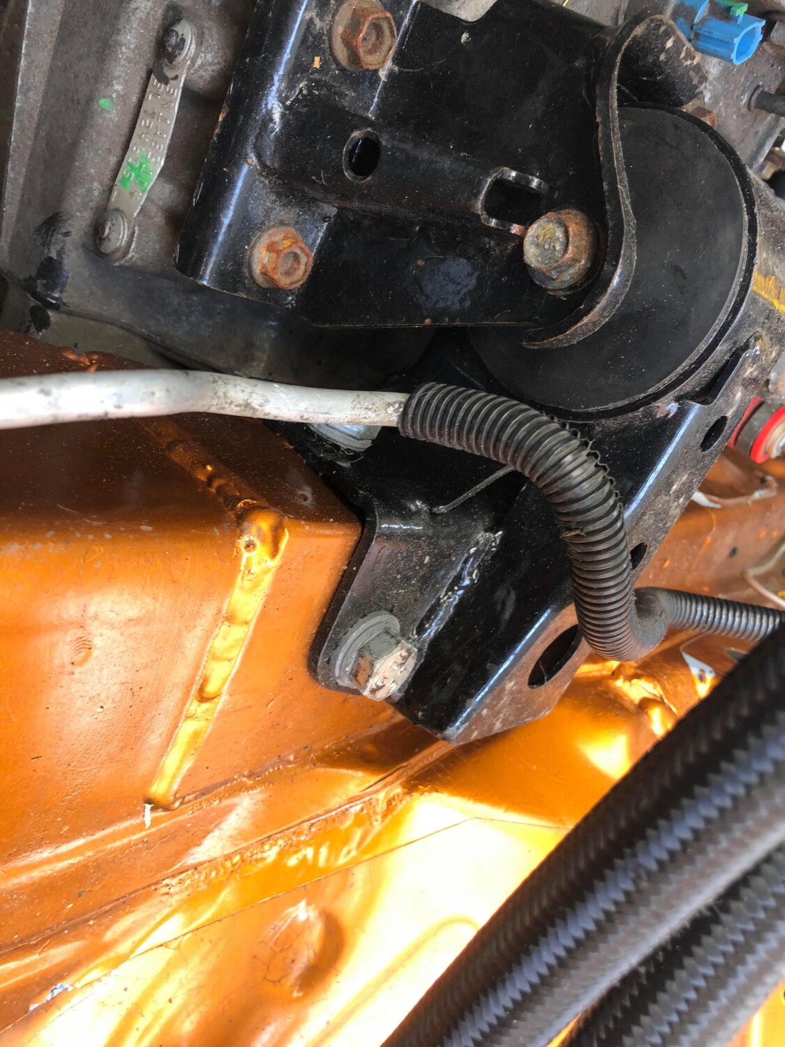
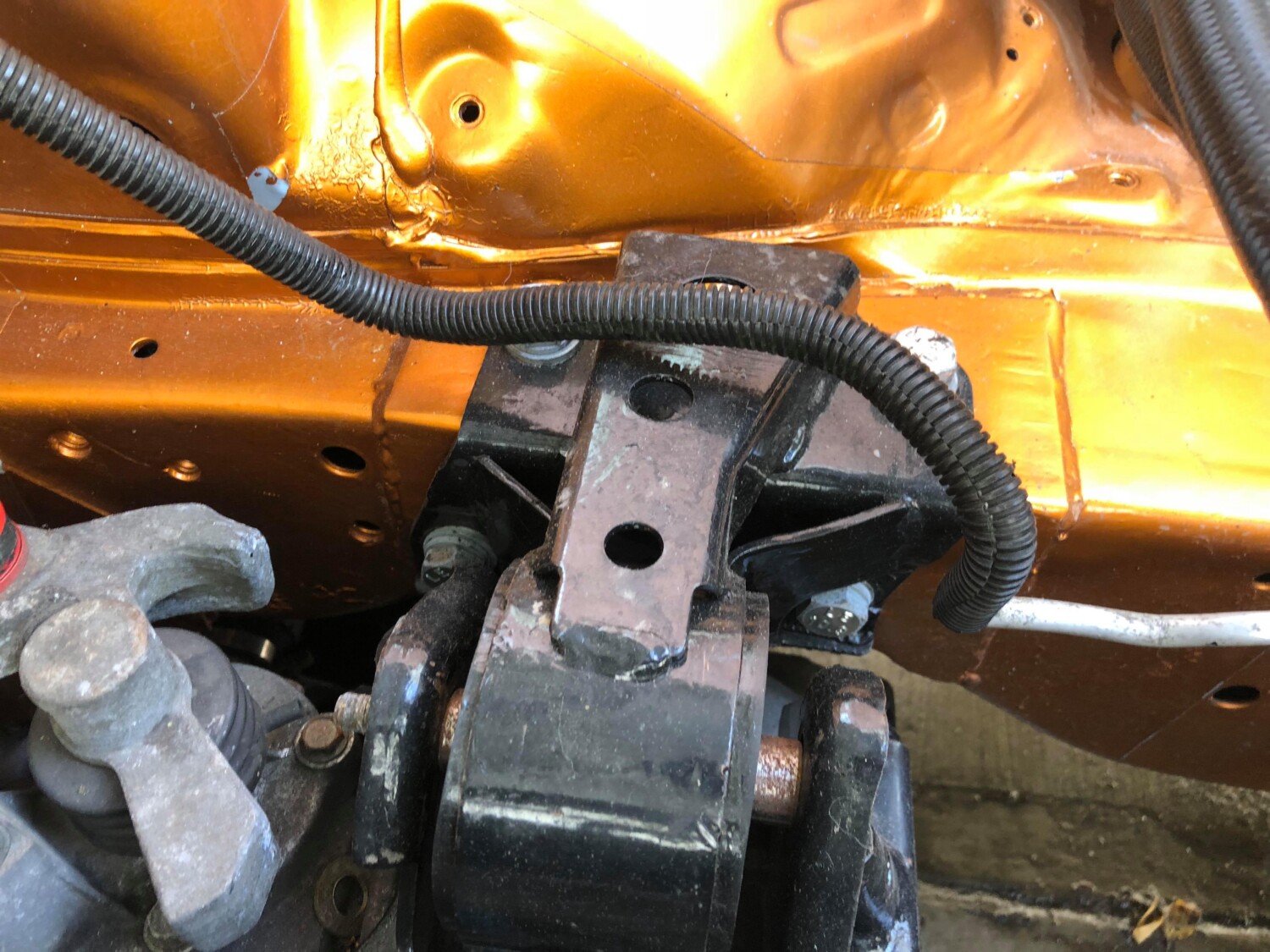
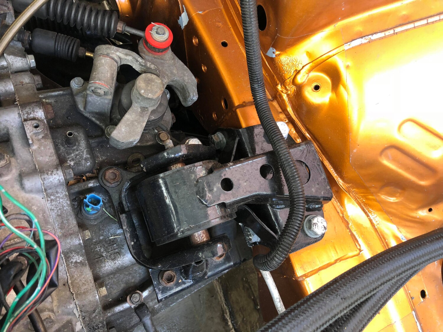
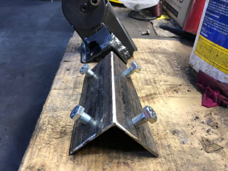
17. Now grind down the rear motor mount peice on top that’s almost just like a cover for the top of the mount, this can be kind of tricky, I’ve found it to almost be easier to undo the mount from the engine and cradle and take out of the car and since all you are grinding is a plate you can just cut it all the way off…photo courtesy of datdude20.
18. Your header/y-pipe should now slide up into place.
19. Bolt on header to head
20. Bolt y-pipe to cat and to front header.

21. Plug in your O2 sensors. You may need to use some zipties on the front because my wire was being hit by the fan so I ziptied it so it wouldn’t hit.
22. Double check and make sure everthing is bolted up tight so you won’t have any leaks.
23. Lower car back onto ground.
24. Re-install fans, intake manfold, intake.
25. Enjoy your headers!!!!
Member Credit: maximaboy12
Hey Guys since I have not seen a thread like this and thought maybe some nOObs will like to have something like this. This fix is not hard be prepared to get dirty.
Tools Needed:
Step 1: Let your car cool down. DO NOT open the cap while the engine is hot.
Step 2: Take off the radiator cap. Once the car is cool unplug the coolant reservoir.
Step 3: Start to take of the 2 hoses attached to the T-Stat. You will need the pliers to take off the clamps and a flat head to slide off the hoses.

***** There are 2 ways to do this you can either flush your coolant or do like I did and just open up the hoses and catch all the coolant in a pan underneath the car.*****
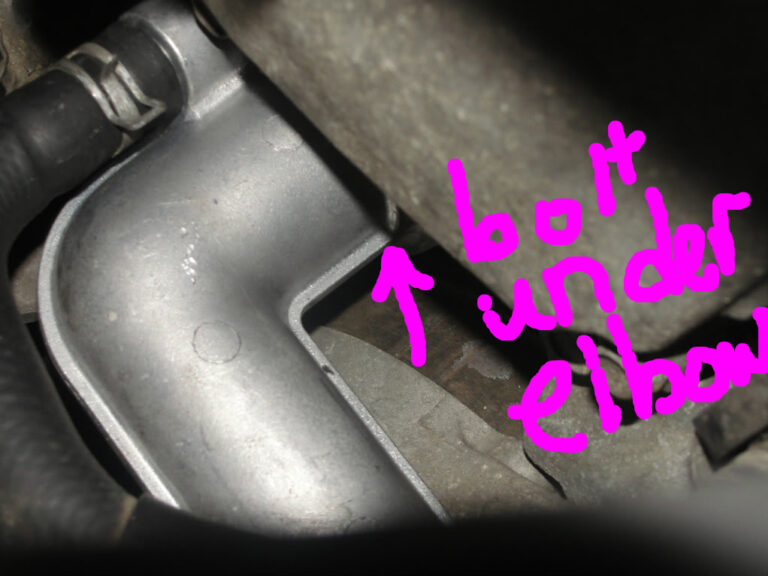
Step 4: Remove all the bolts holding the T-Stat in. I believe there are 3. This is where the ratchet comes in. It really would be good if you have a smaller set with a swivel head.


**** The Third Bolt is under this elbow****
Step 5: Take out the T-Stat and replace with new one and the new gasket dont forget to put a lil sealent on the gasket. A new OEM T-Stat on ebay runs for about $25 Bucks shipped.
Step 6: Refill your radiator. If your coolant has bits and lil pieces of trash pour new coolant in. You dont want that crap in your engine.
Step 7: Turn the car on and blast the heat. Check for leaks.