Tag

Engine, Trans, F/I & Tuning

Browsing

Member Credit: sdot82

This write-up is for a 2000-01 VI manifold swap on to 95-99 Maxima. There are many ways to do this swap so first I will number the ways I know how to do this and then go into detail on how to do it. There are a couple of different Upper manifolds you can get Fed spec. or Cali Spec the difference is one may not have the swirl valve control (don’t need it anyway). I believe (don’t quote me on this) that the 00 Fed Spec do not have the swirl valve control and all 01 (Fed and Cali) do not have the hole for the EGR guide tube. You may want to ask the People from the Junkyard this because you want to know this if you are going to keep the EGR or not.

(note when I say 00 that means both 2000-2001 unless I specifically say otherwise for that part)

  1. 00 Upper and Lower (Fed spec), 00 Fuel rail & injectors or 01 QX4 fuel rail & injectors (they are the same because I am using the QX4 fuel rail and inj.), 00 Throttle Body w/ 00 IACV, 00 EGR guide tube. (no adaptors needed for this)
  2. 00 Upper and Lower (Fed or Cali), 00 Fuel R&Inj. Or 01 QX4 Fuel R&Inj, 00 TB w/ 00 IACV, and running no EGR. (Make a plate to cover the hole in the manifold)
  3. 00 Upper and Lower, 00 Fuel R&Inj or 01 QX4 Fuel R&Inj, 00 TB w 4th gen IACV (need a adaptor plate made for the 4th gen IACV), and 00 EGR guide tube or no EGR (need to make a plate to cover the hole)
  4. 00 Upper and Lower, 00 Fuel R&Inj or 01 QX4 Fuel R&Inj, Pathfinder TB (need a adaptor plate made) 4th gen IACV (need a adaptor plate made), and 00 EGR guide tube or no EGR (need to make a plate to cover the hole).
  5. 00 Upper and Lower, 00 Fuel R&Inj or 01 QX4 Fuel R&Inj, 4th gen TB (need a adaptor plate made) 4th gen IACV (need a adaptor plate made), and 00 EGR guide tube or no EGR (need to make a plate to cover the hole).
  6. 00 Upper and 4th gen Lower, 4th gen Fuel R&Inj, 00 TB w/ 00 IACV, and 00 EGR guide Tube or no EGR (need to make a plate to cover the hole).
  7. 00 Upper and 4th gen lower, 4th gen Fuel R&Inj, 4th gen TB, 4th gen IACV, 00 EGR guide tube or no EGR.
  8. 00 Upper and 4th gen lower, 4th gen Fuel R&Inj, Pathfinder TB, 4th gen IACV, 00 EGR guide tube or no EGR (need to make a plate to cover the hole).

I think those are all the different ways that u can do the swap parts wise. In addition to those parts listed above you need to get:

  • a lot of new hoses (different sizes), some fittings and tees.
  • hose clamps
  • new gaskets for the 00 lower, the upper should not need new gaskets since they are rubber (unless they are torn)
  • Bolts for the upper manifold (8 of them) unless it came with it, should be able to reuse the lower manifold’s bolts.
  • New bolts for the VIAS back cover (metal cover) and the vacuum switch (just a suggestion because you might have to take it off later and the OEM screws strip easy).
  • Bolts for the 00 TB, if you are going with the 4th gen or Pathy TB you will have to find out from the person you get the adapter plates from what bolts are needed.
  • Adapter Plates for 4th gen TB, 4th gen IACV, or Pathy TB
  • Cover Plates for EGR or 00 IACV (explain later)
  • JB weld the liquid type and JB weld Stick
  • New different PCV w/hoses

Tools:

  • Dremel or grinder
  • socket set (deep as well as regular) you will mainly use 14mm, 12mm, 11mm, 10mm so get those in deep socket.
  • Flathead, and Phillips head screwdrivers

Prep. work, before you start installing you want to do a couple of things:

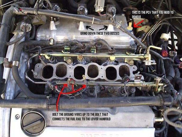
  • If you are using the 5th gen lower and it has the swirl valve, remove everything so it’s just like the 4th gen (See PIC 4 below). Once it’s removed use some the JB Weld Stick to cover the holes so there will be no leaks. I just plugged the two outside holes (see pic the holes are highlighted in red.)

    Pic 4
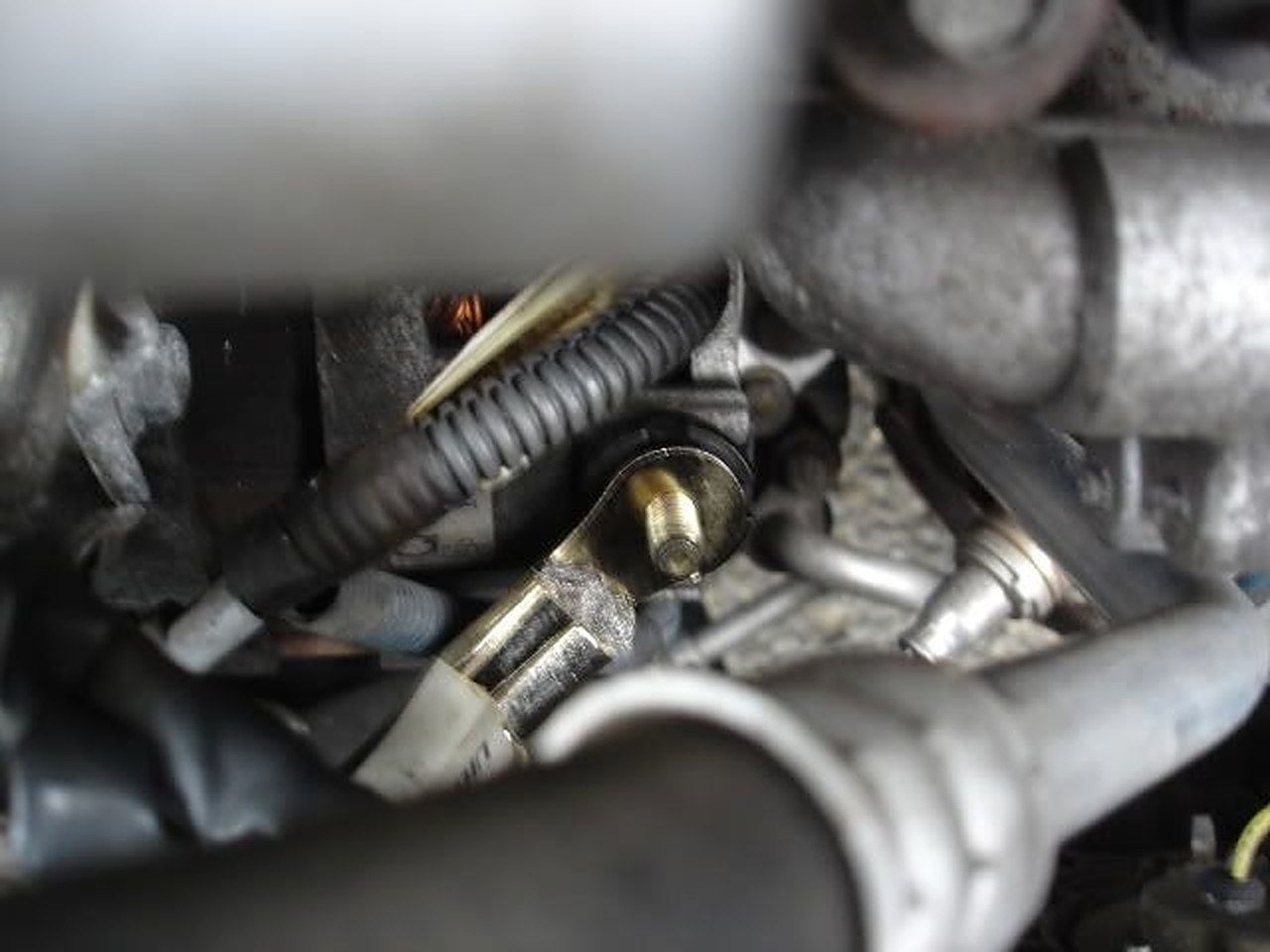
  • Also, you want to either fix or just prevent the VIAS from breaking by using the regular liquid JB Weld. If you want to you can replace the bolts that hold the VIAS solenoid and the metal plate on the there side in place (see pic). I had to because one of the screws stripped on me so I went to Home Depot & bought a kit that removes stripped bolts or screws.
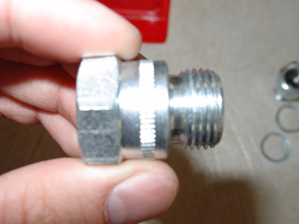
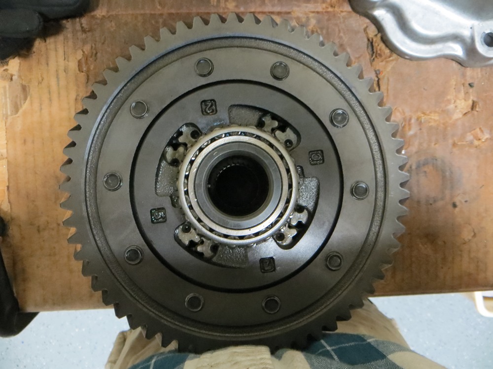
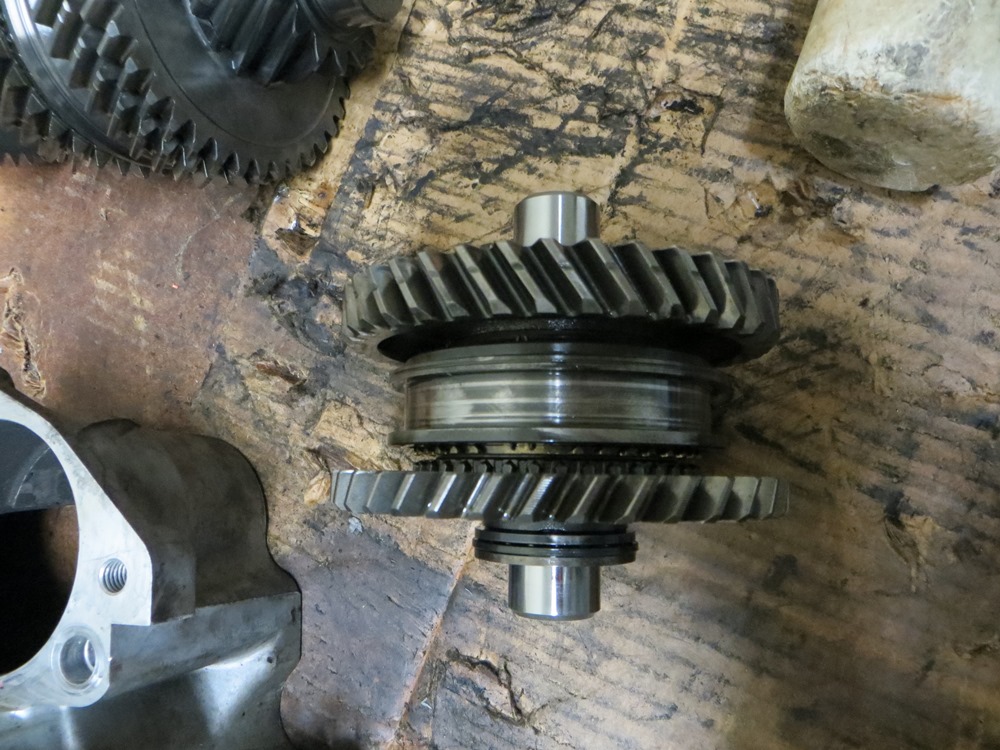
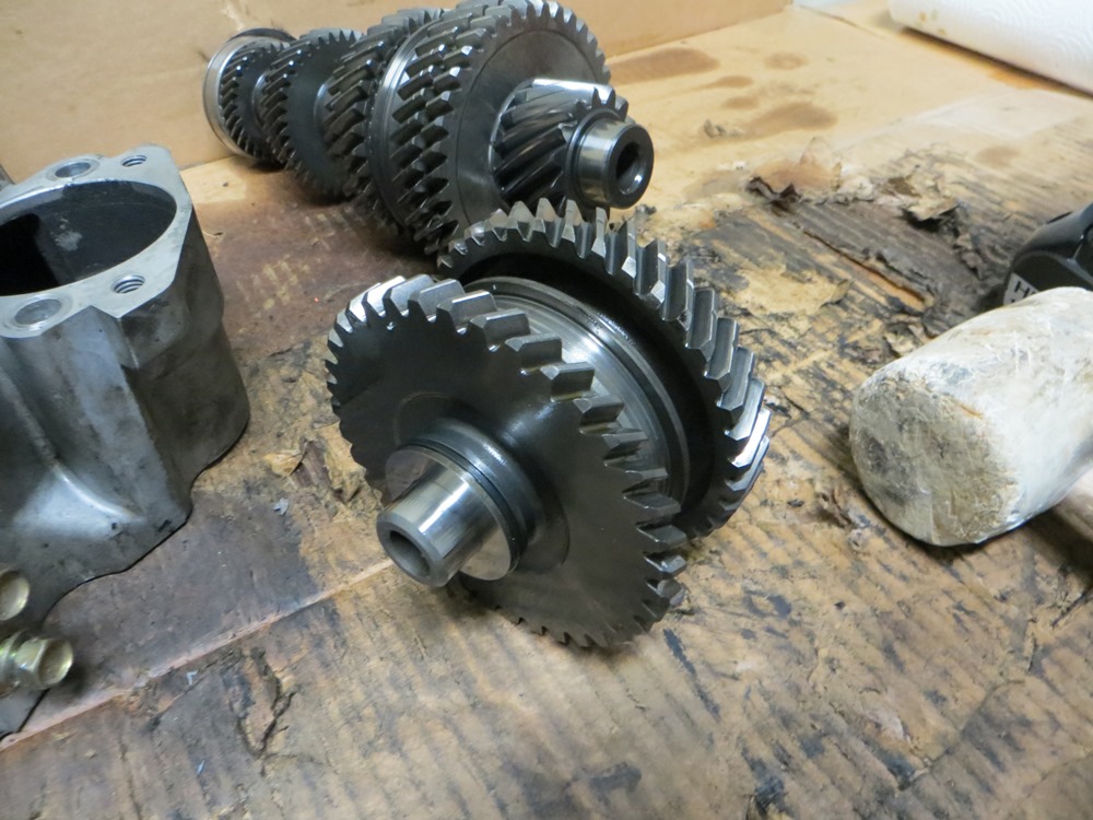
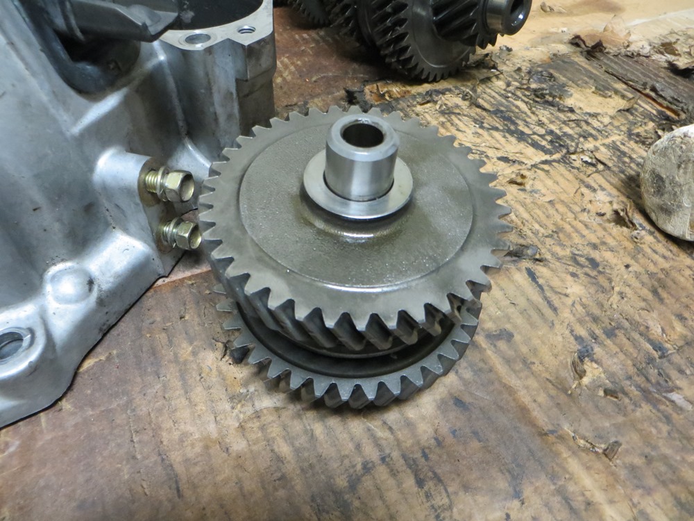
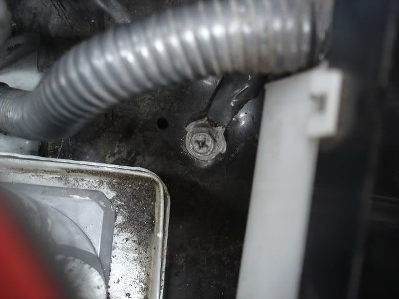
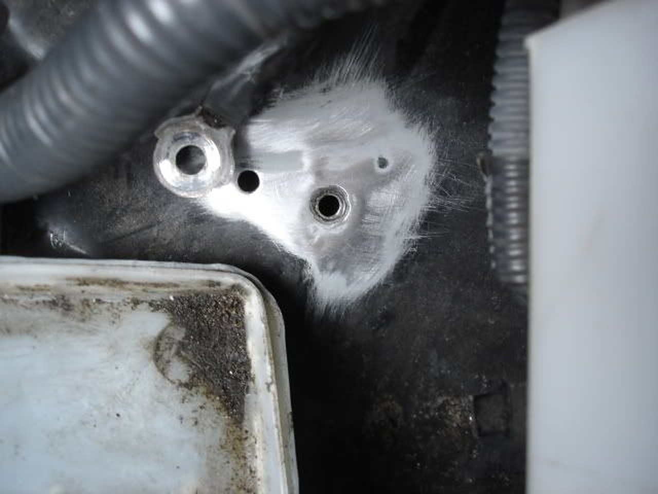
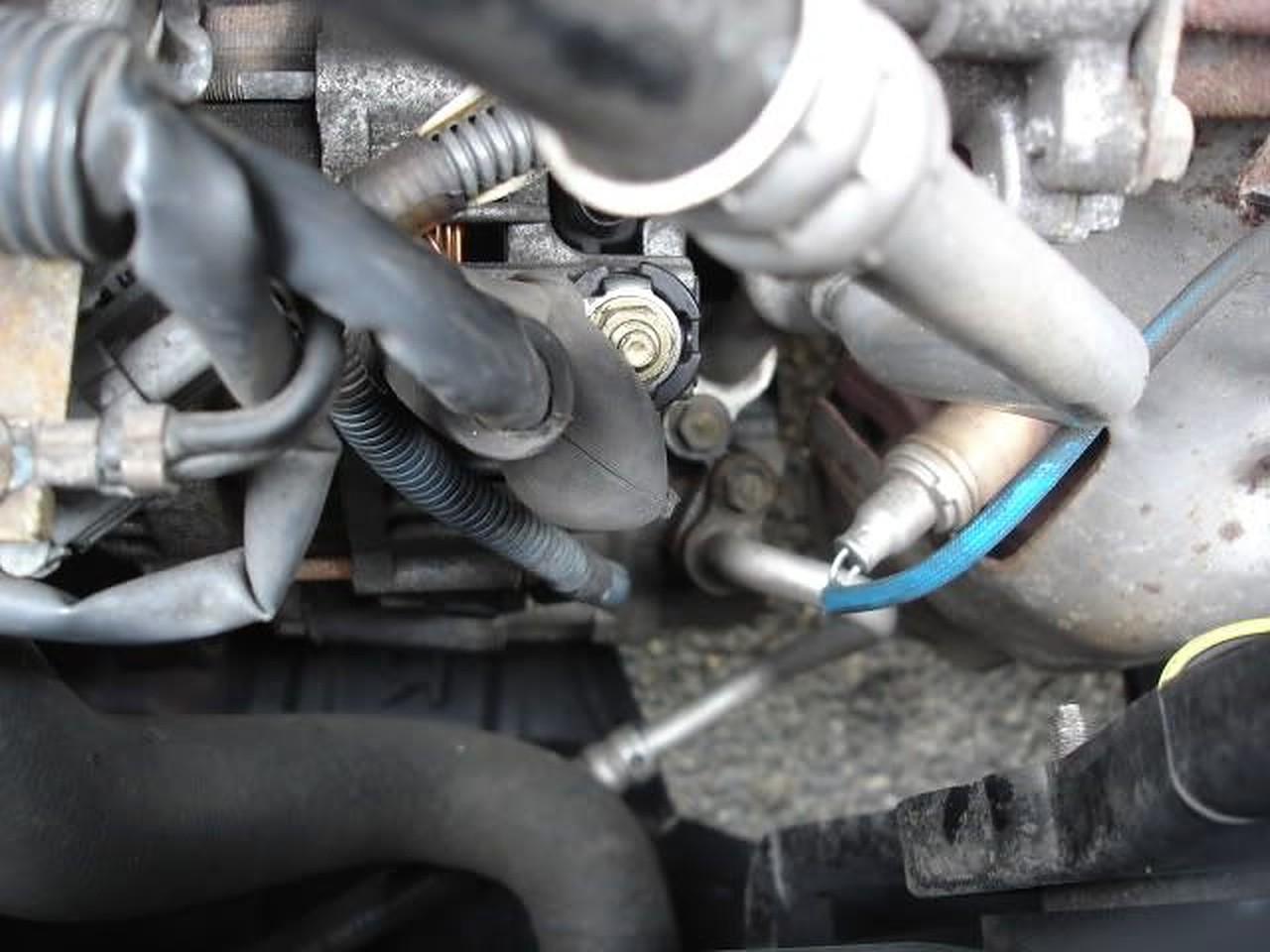
  • Fuel rail depending if you went with the 2000 Maxima fuel rail you will have to buy something like that (see pic 1 & 2 ), and if you used The 01 QX4 fuel rail you can do what I did (see pic 3). I took off the piece you see in the pic and used a grinder to cut off the extra metal tube and bent it into place so it would reach the fuel line hose. It did not line up exactly with the hole so I just screwed in one side of the fitting and have no problems with it. I made it just like the 4th gen fuel set up wise (like the place of the FPR).
    Pic 1
    Pic 2

    Pic 3
  • First go to the fuse box located on the dash of you car and remove the fuel pump fuse. Then you want to start your car and let it run until it dies, do this process until you can’t start you car at all. This will remove most of the fuel out of your fuel rail and injectors.
  • Next up remove your intake (note: I would label all of you hose either by marking it with something or with numbered stickers, and right it down in a note book what it means).
  • On the Throttle body disconnect the plugs from the TBS and the cables. Now get a towel or a container so you can catch the antifreeze when you remove the hoses on the bottom of the Throttle body. Once you have everything disconnected from the TB remove the (12mm) bolts in the throttle body.
  • Start disconnecting all three coil packs, IACV plugs, and other wires to clear up space when removing the upper manifold.
  • After you have the TB off start removing all hoses and components that are on the upper intake manifold and labeling them. When you have everything off the upper manifold, begin removing the bolts in the front of the upper manifold (note: there are 2 bolts on the back of the upper manifold that you will have to remove). Remove the ERG guide as well.
  • For those that are using 4th gen fuel rail and 4th gen lower manifold skip to preparing the engine for the upper manifold. If you using the 5th gen parts read on
  • Once the upper manifold is remove began removing the fuel rail, I remove the fuel hoses first (I placed a towel around the hose from the fuel filter to the fuel rail so gas would not spill onto the engine). Then remove the bolts for both the fuel rail and lower manifold.
  • Once you have removed the lower 4th gen manifold you can now place the 5th gen lower manifold and bolt it up.
  • Then you can put then new fuel rail on the lower (if you are using a 2001 QX4 one or to of the holes will not line up, like mines, but it will still be good). The next thing you don’t have to do I just did: you’ll need the rubber washers that came of your old fuel injectors to place them around each of your new injectors. I did this because there was a gap from the lower manifold to the fuel injectors. After you bolt the fuel rail down it’s time to cut the old 4th gen fuel injector connectors off and solder them (or connect them anyway you want to) to the 5th gen connectors. Most people don’t like cutting wires but it’s not hard. Also, you need to grind the fuel rail (I bolted them down onto the lower manifold because it was the easiest location for me.) Now get some of the new hoses that you should have purchased and connect them from the fuel filter to fuel rail and fuel rail to fuel filter.

Preparing the engine for the upper manifold

Now that the lower manifold and fuel rail are on, cover up the holes in the lower manifold so nothing can get inside. Remove the PCV out of your valve cover because it will not let the upper manifold sit properly on the lower manifold (later I will tell you what I did for this).

For the next part, you will need your grinder or Dremel. You will need to grind down the coil pack mounting bosses BUT ONLY THE FRONT MOUNTING BOSSES#3 AND #5( SEE PIC ABOVE). #3 and #5 are the ones to the right of you if you are standing in front of the car looking at the engine. Grind down as much as you need to just keep putting the upper manifold on to check for clearance. Once you are done clean up the mess you made grinding down the bosses.

Next up is the PCV, you should have bought a new PCV valve one that would allow you to connect to some hoses. The hose’s outside diameter should be ½ inch for it to fit in the valve case hole tight and cut it to be about 6-8 inches long. You might have to lubricate the hose for it to slide in (at least that’s what my girl keeps telling me j/k lol).

Note this is only for people that are keeping the EGR and 5th gen IACV.

Loading

If you are reading this article, you are very likely trying to resolve P0420/P0430 without having to spend a lot of money on the issue. Most of the time, the codes are due to a bad clogged catalytic converter or bad O2 sensors. Before replacing the O2 sensor, be sure to do the spacer fix modification first because O2 sensors are not cheap.

There aren’t usually any drivability issues associated with these codes. For most people, the first sign that anything is wrong at all is the check engine light. Below are the typical check engine lights you would normally get:

  • P0420 NISSAN – Catalyst System Efficiency Below Threshold Bank 1
  • P0430 NISSAN – Catalyst System Efficiency Below Threshold Bank 2

The Fix

You can eliminate the codes by using a spark plug non-fouler which tricks your engine computer to think that everything is working fine. This simple trick will pull the O2 sensor away from the exhaust flow and the computer will think the Catalytic converter is working properly. This will work if you remove the catalytic converter or have a bad cat. It’s very simple and cheap to do. Below is a video on how to perform the fix:

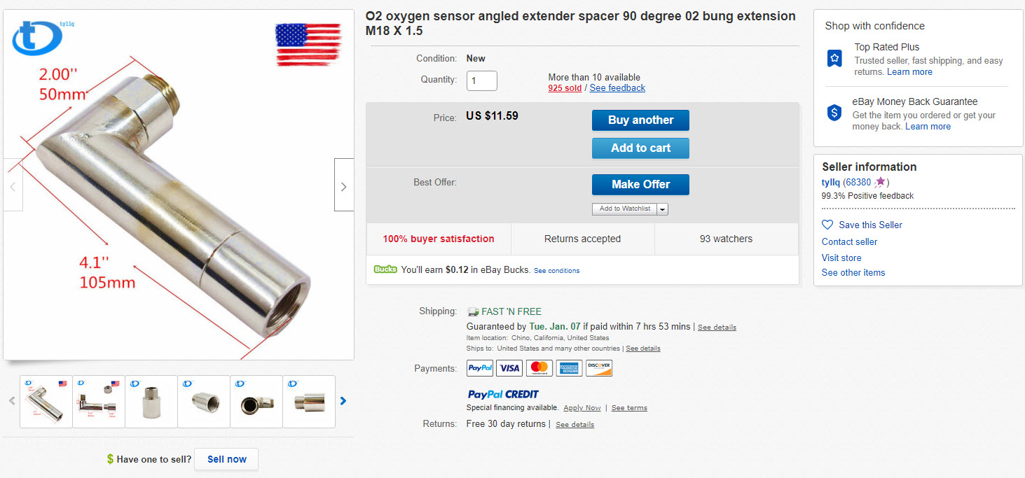
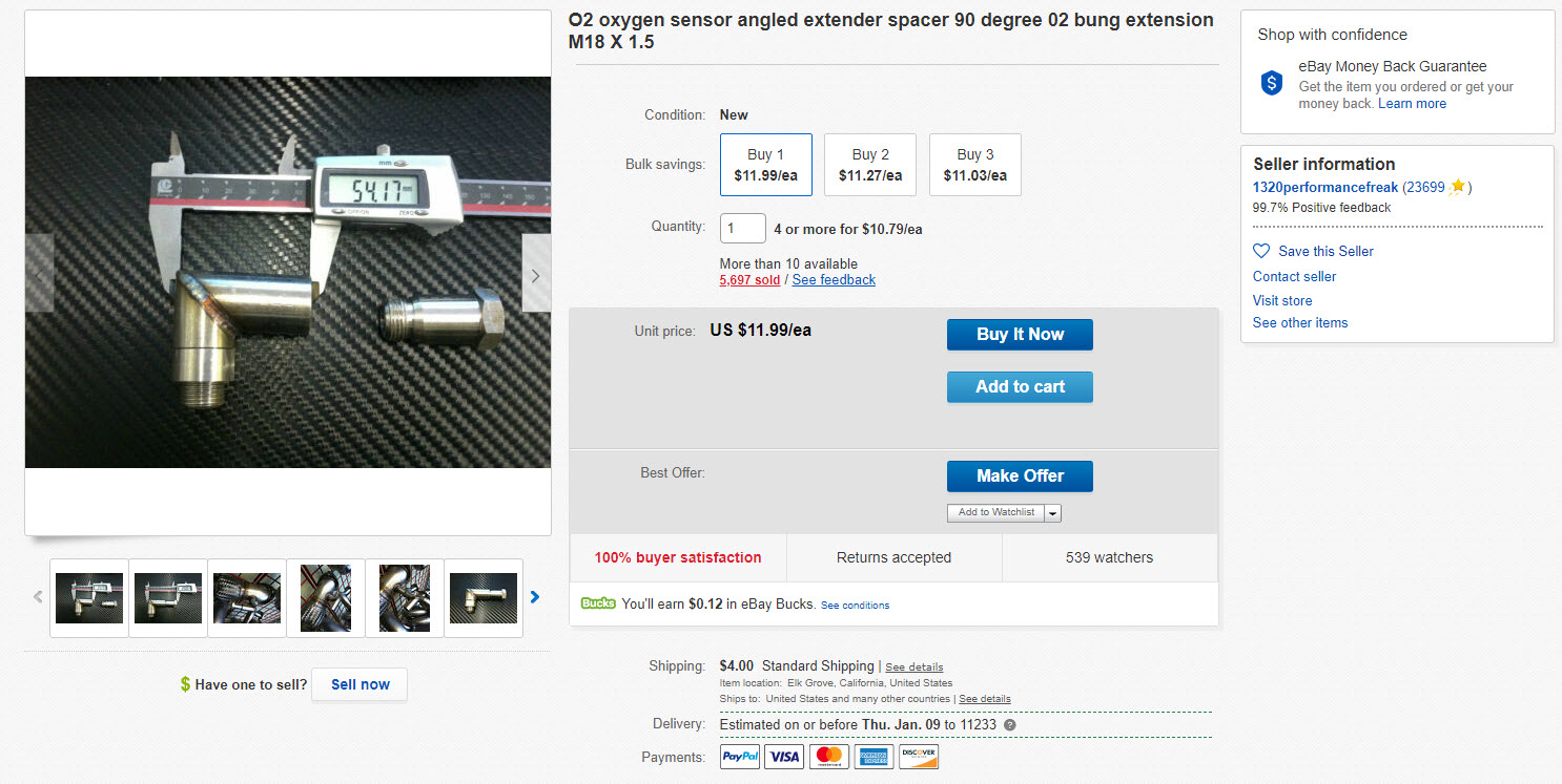
You can also buy them pre-made on eBay if you do not want to drill.


Make Your Own Spacers/Foulers

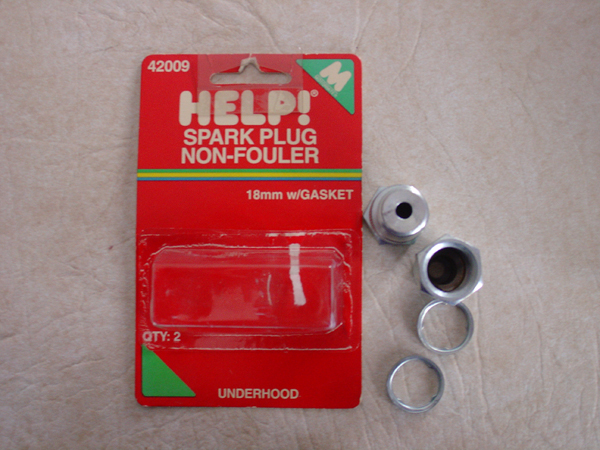
You can buy these non-fouler spacers at your local parts store. You can get them from Advanced Auto or Autozone for about $7-8 bucks.

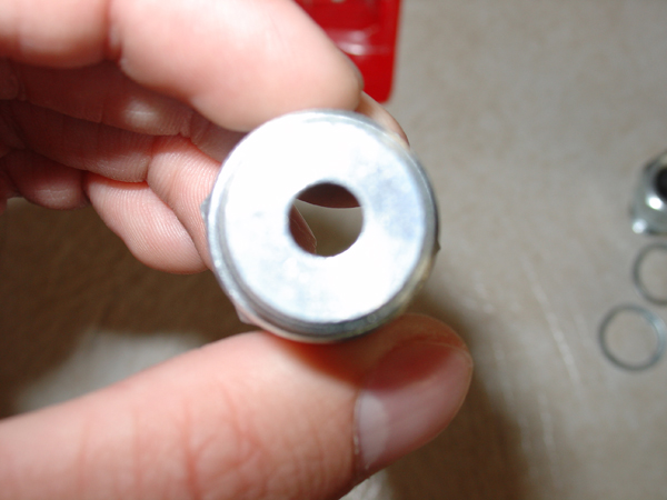
You now need to drill out 1 of the non-foulers using a 1/2″ drill bit. When finished this is what it will look like.

O2 Sensor inserted in the modified non-fouler

Second, unmodified non-fouler now installed on modified non-fouler, then threaded into the pipe

Reference Photos

Below are photos of the spacers installed and 100% working on Nissan Maximas by generation. After installing the spacers, the CEL codes went away.

5thgen Nissan Maxima

6thgen Nissan Maxima

7thgen Nissan Maxima

Loading

Member Credit: 6spd_Hayes

Disclaimer: If you attempt any of what you see from my post, you do so at your own risk. The following is a summary of my experience.

The Car: 2002 Maxima SE
Transmission: 6 speed, HLSD, RS6F51A
Mileage: 174,000 mi. (approx.)
Situation: November 1st, 2014. I jumped in the Maxima, running late to a funeral in Tennessee. Pushed clutch to floor and started it. I could not get gear shifter out of third gear no matter how hard I tried. Something was obviously broken in the transmission.

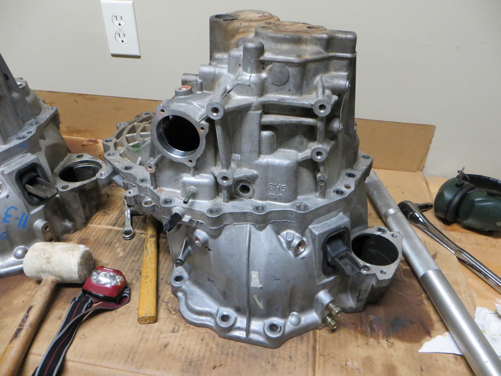
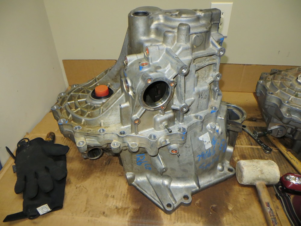
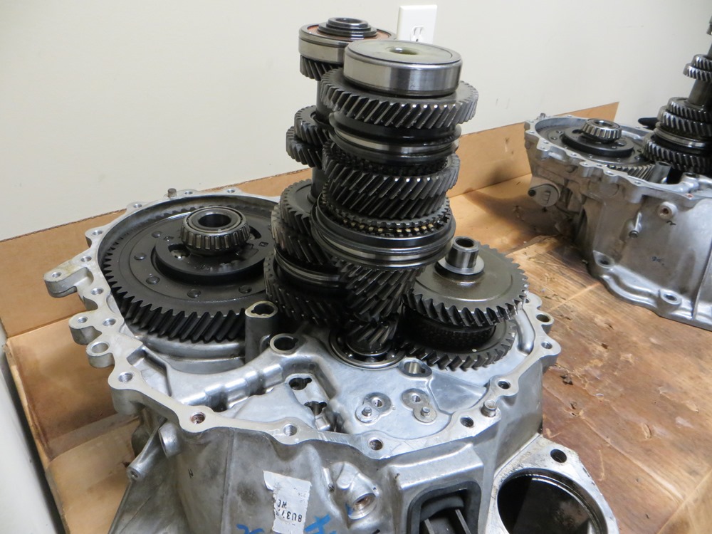
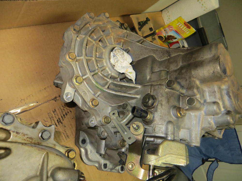
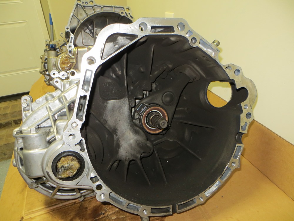
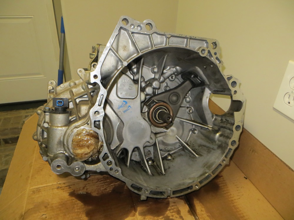
After a lot of online research, I purchased a 29,066 mile 6 speed, HLSD transmission from a 2006 Nissan Sentra Spec-V (p/n RS6F51H) from http://car-part.com/. Kindly gentlemen cargo shipped it from a junkyard in Arkansas to my door step in North Alabama for $XXX (will update when I remember it). The following were the only differences in the two transmissions: (1) bellhousings were different, (2) final drive ratio were different (3.812 vs 4.133), (3) Maxima – 1st & 2nd gear dual synchro, SpecV – 1st gear dual synchro, 2nd gear triple synchro.

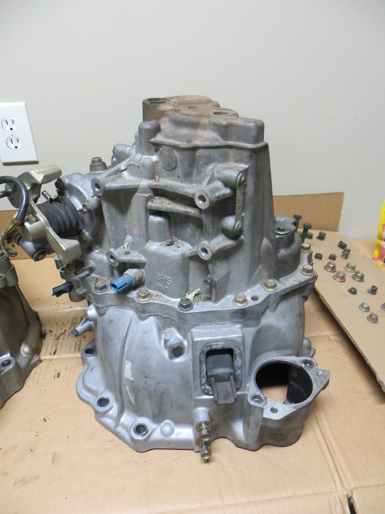
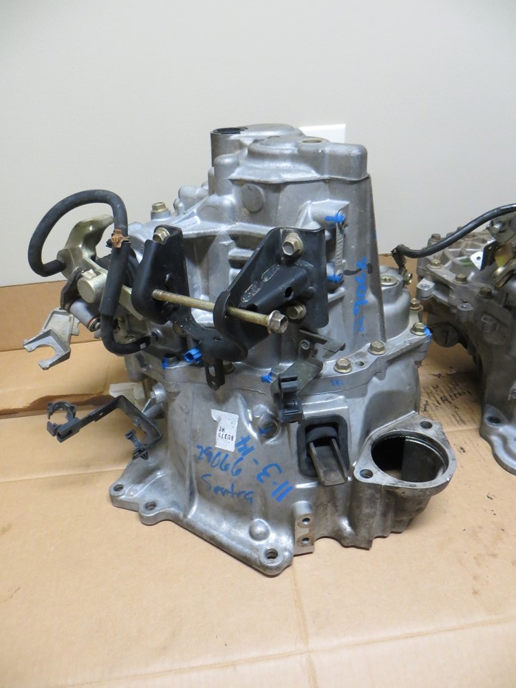
Sentra SpecV Transmission As Received:

Work Setup:

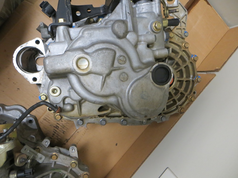
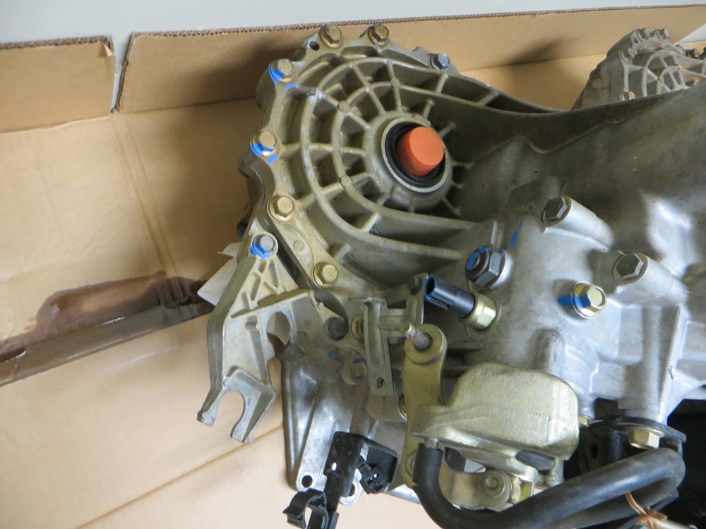
  • Set each transmission on cardboard covered work bench side by side (cardboard to protect mating surfaces on transmission and soak up any grease/oil/fluids)
  • For fasteners, blow up and print out FSM pages and glue to cardboard. Poke fasteners through on board where you take them out of transmission
  • Take off parts from each transmission at same time, label in Ziploc bag
  • For large parts, label and place in its own cardboard box
  • Clean as you go (scrape off gasket material, use acetone/cloth) to clean
  • Follow both factory service manuals for breakdown/buildup

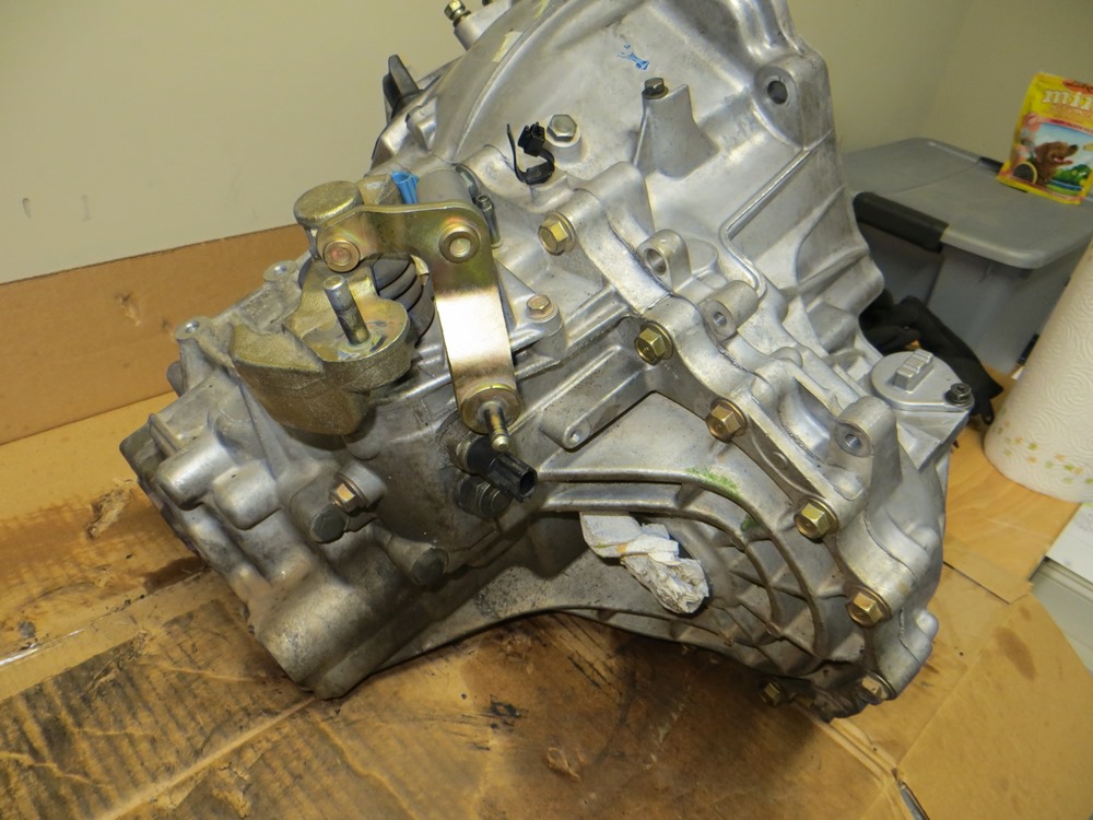
Maxima

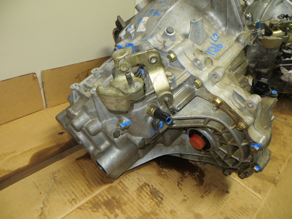
SpecV

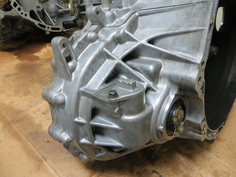
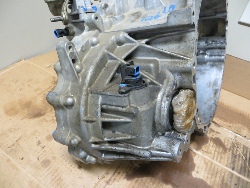
Maxima Speedo Sensor Block-off Plate

SpecV Speedo Sensor

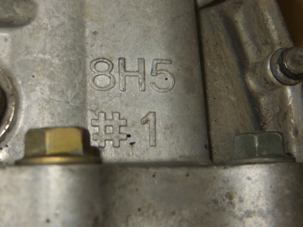
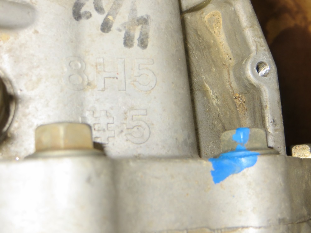
Maxima Transaxel Case Stamp

SpecV Transaxel Case Stamp

Maxima

SpecV

Maxima Control Assembly, Sensors, and Case Bolts Removed

SpecV Control Assembly, Sensors, and Case Bolts Removed

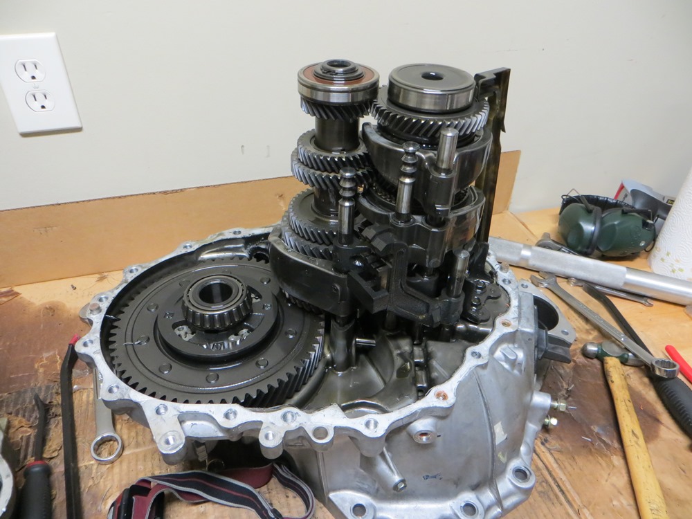
Maxima Transaxel Case Removed (at this point forward, they both look the same

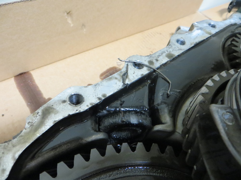
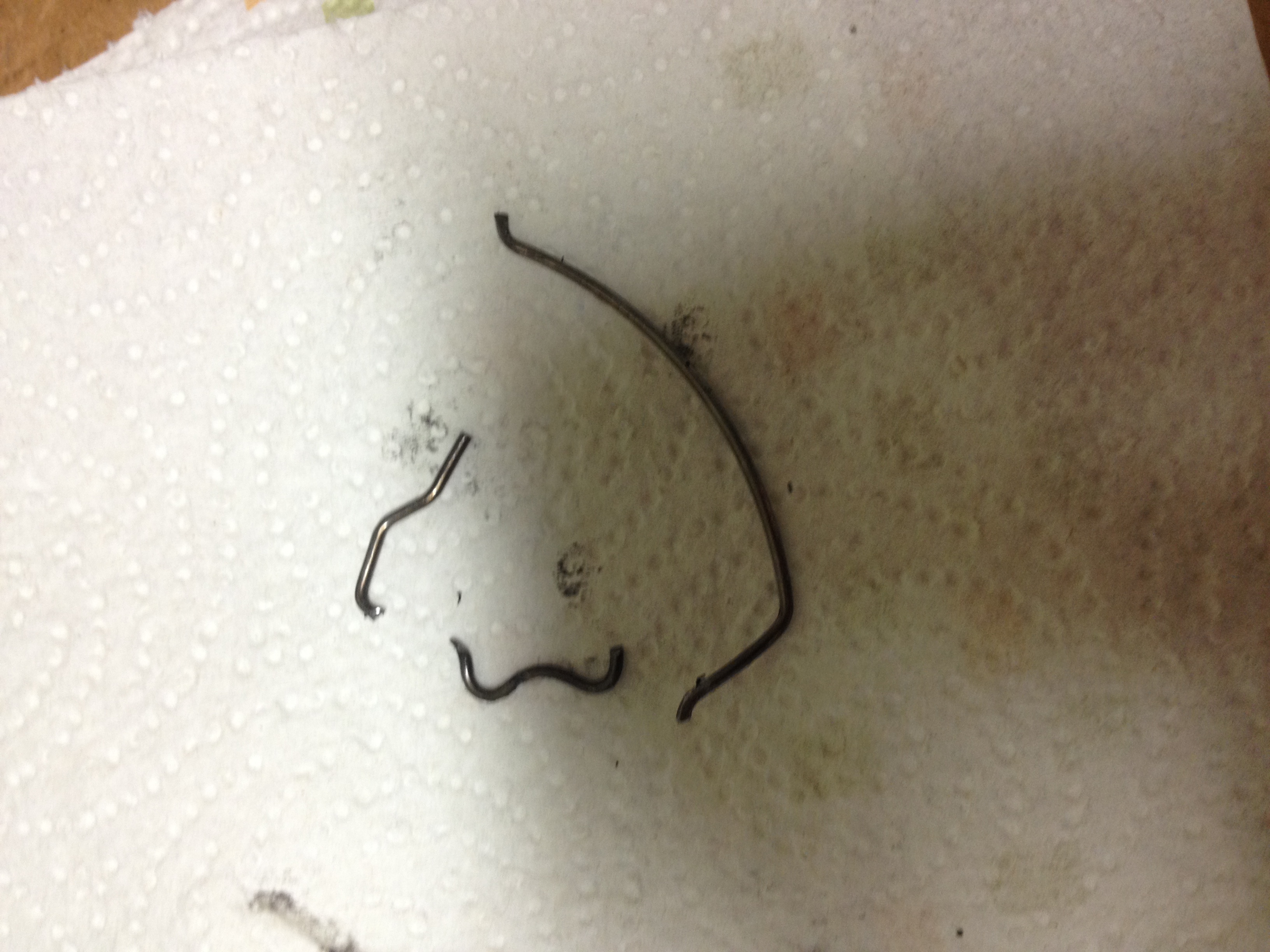
Maxima Spread Spring Debris and Detail

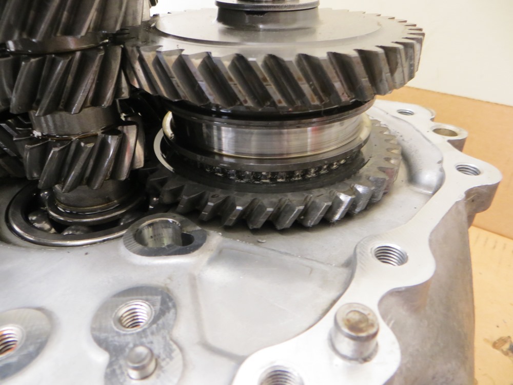
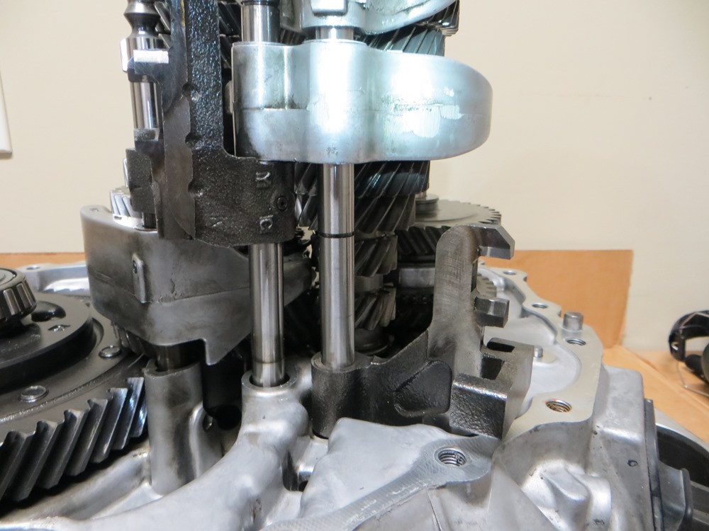
Based on the pictures below, it appears the spread spring in the 3rd-4th synchronizer broke and lodged itself in to prevent the sliding action between gears.

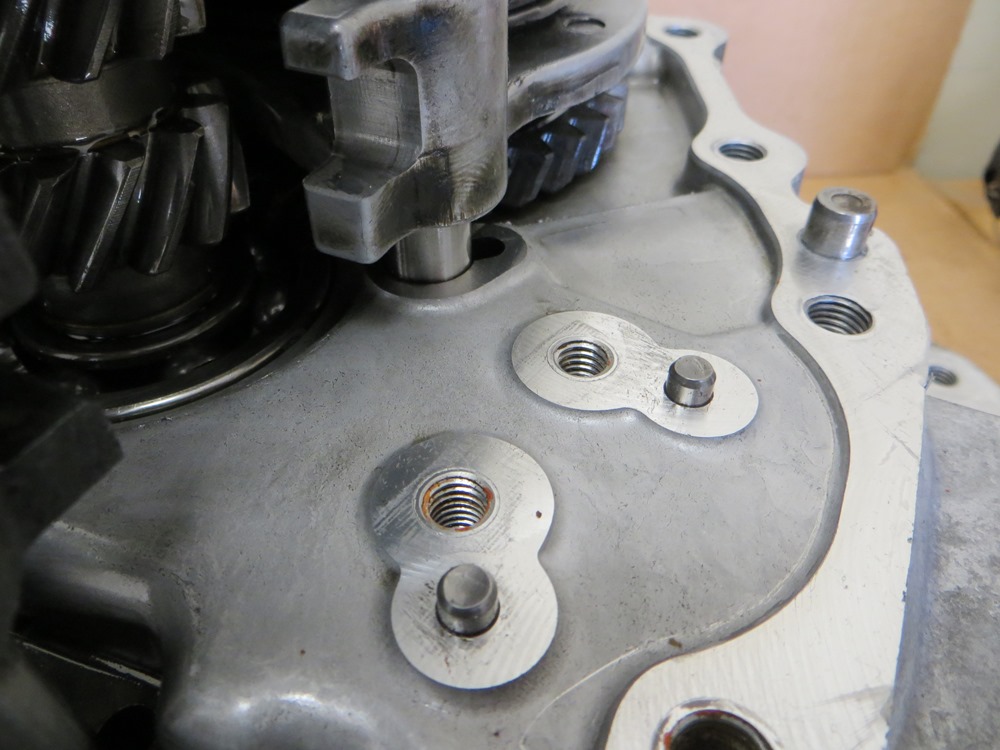
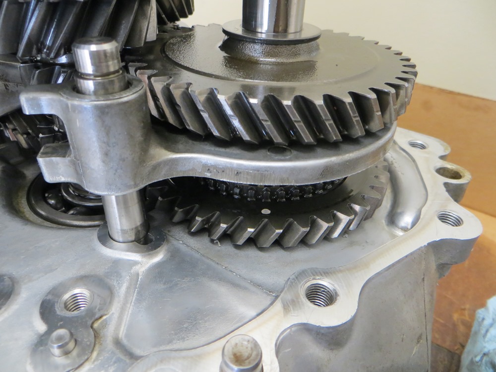
Maxima – Reverse Tilt Mechanism Removed

Maxima – Re-test fitting reverse tilt mechanism (to make sure I understood its reassembly)

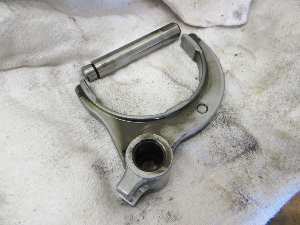
Maxima – Reverse shift fork and rod

Maxima – Reverse Gear Stack

Maxima – Re-test fit reverse shift fork

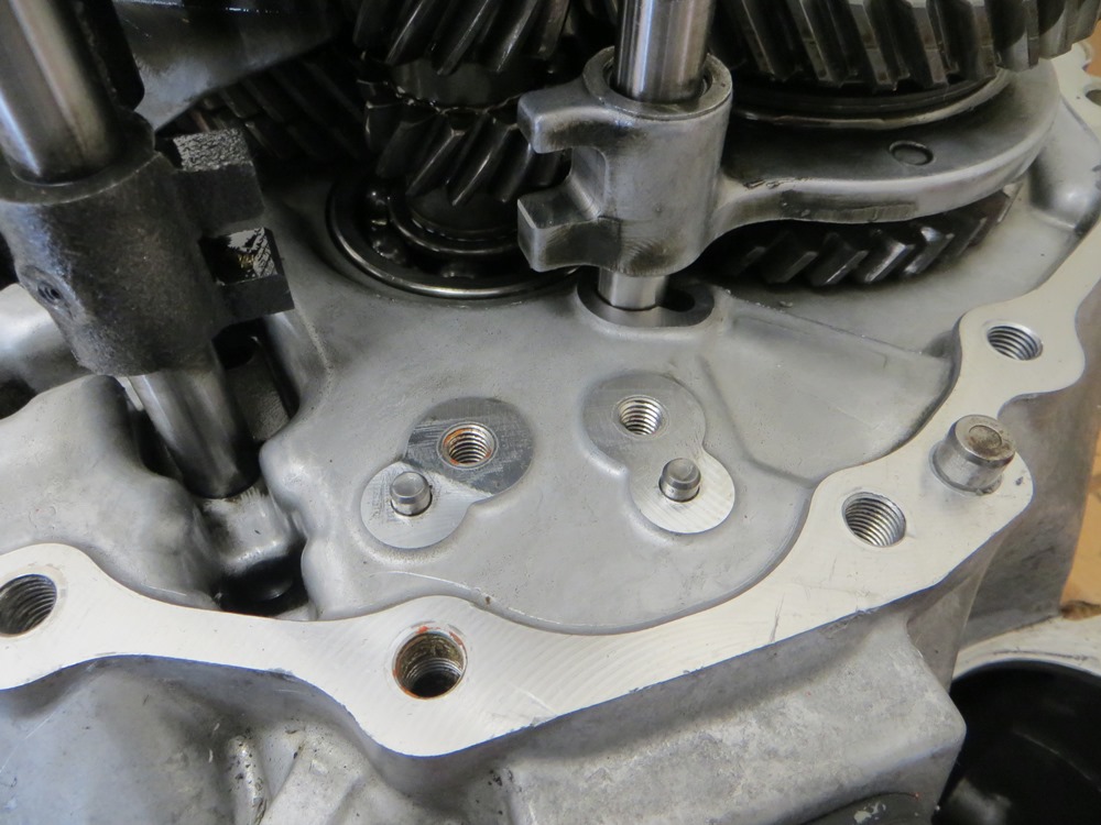
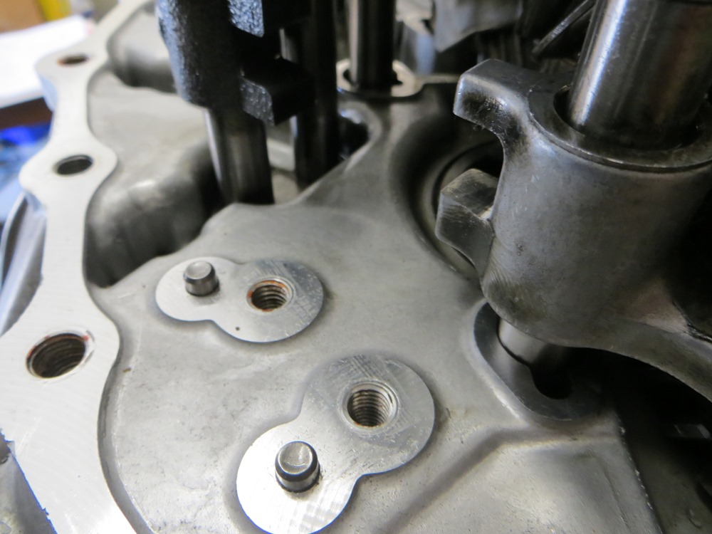
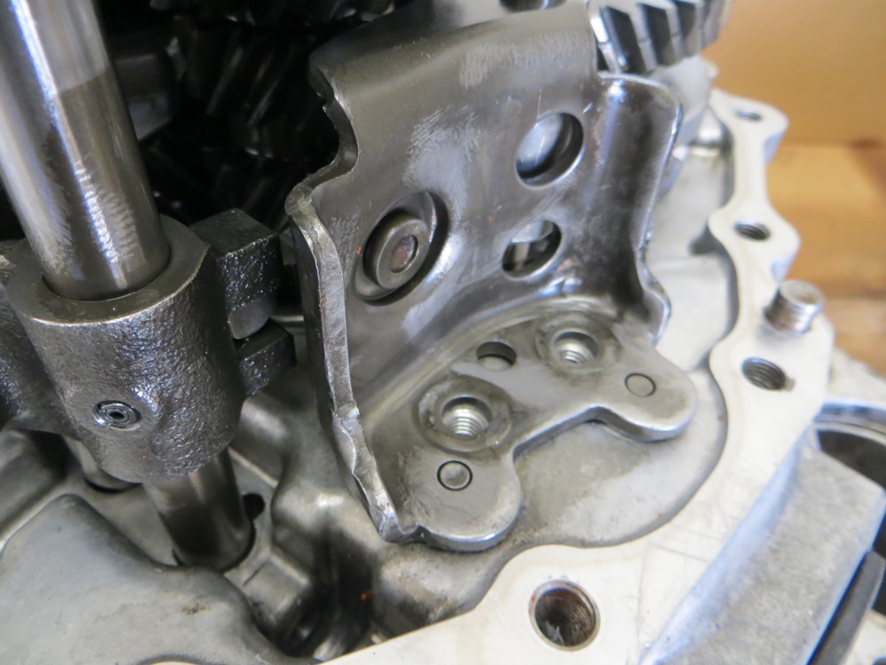
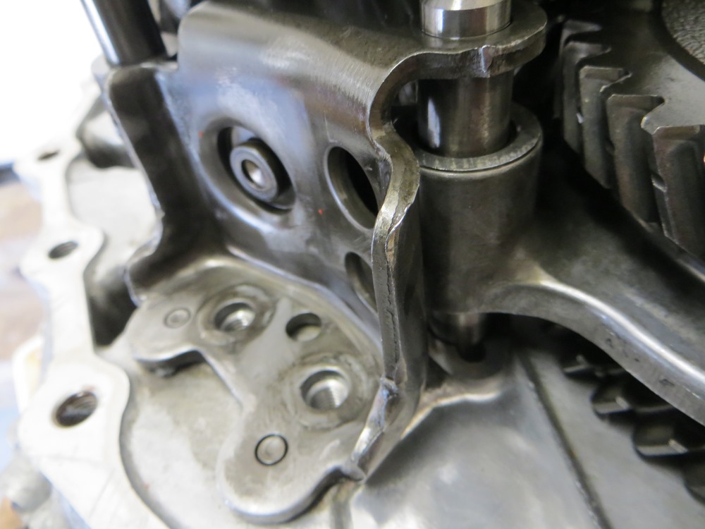
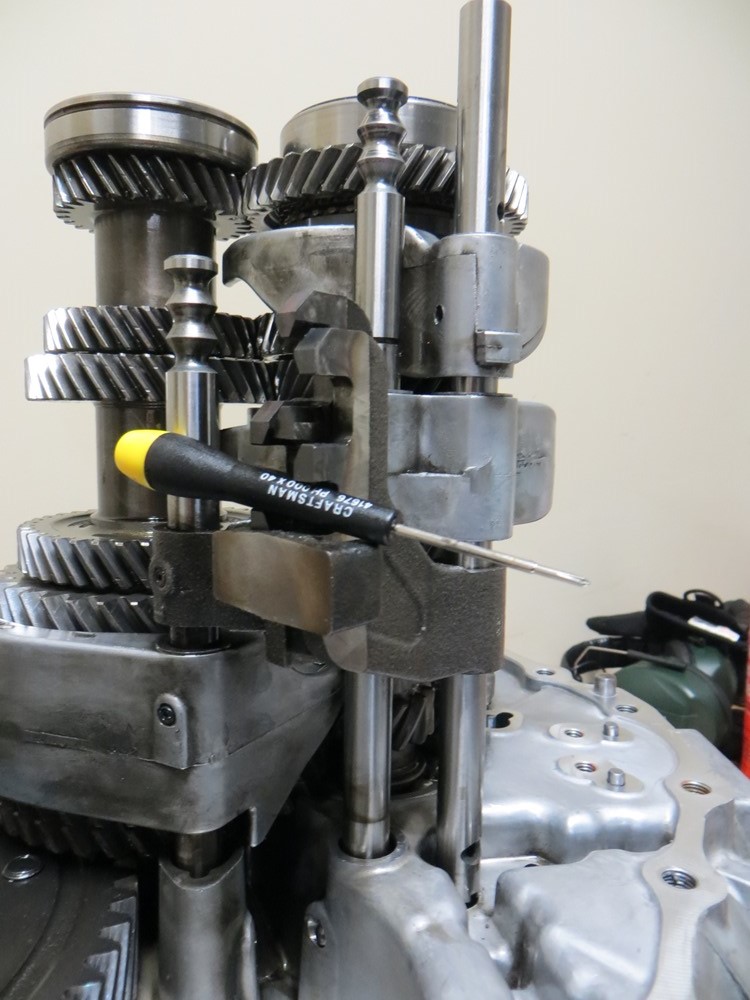
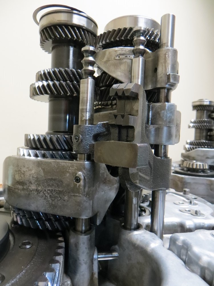
Maxima – Shifter bracket Detail

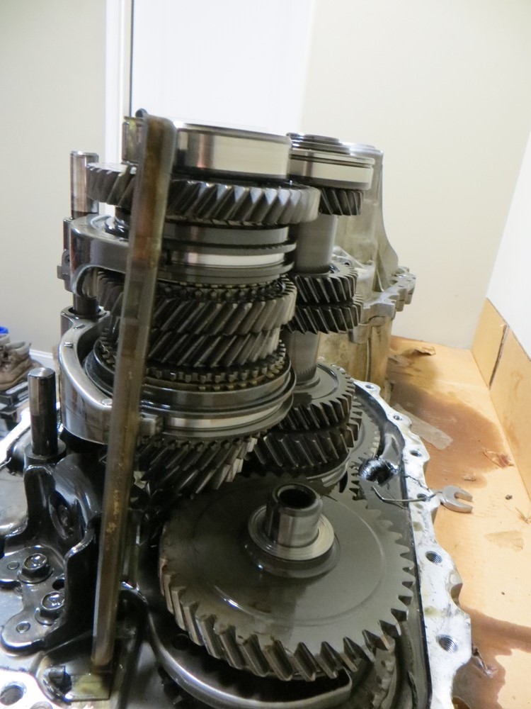
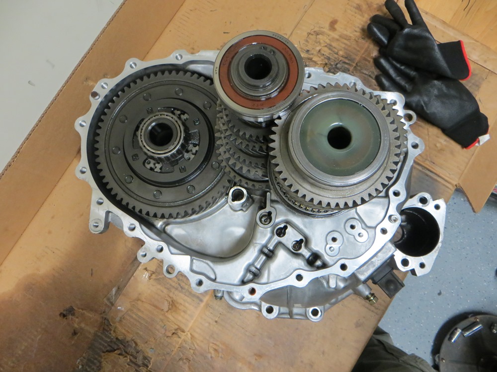
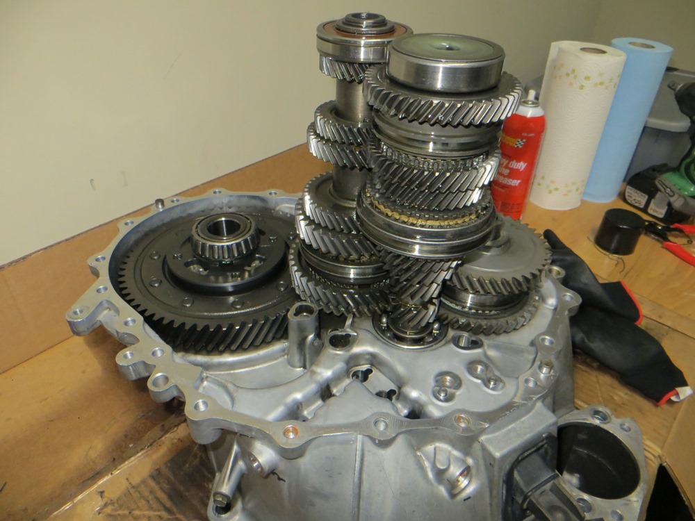
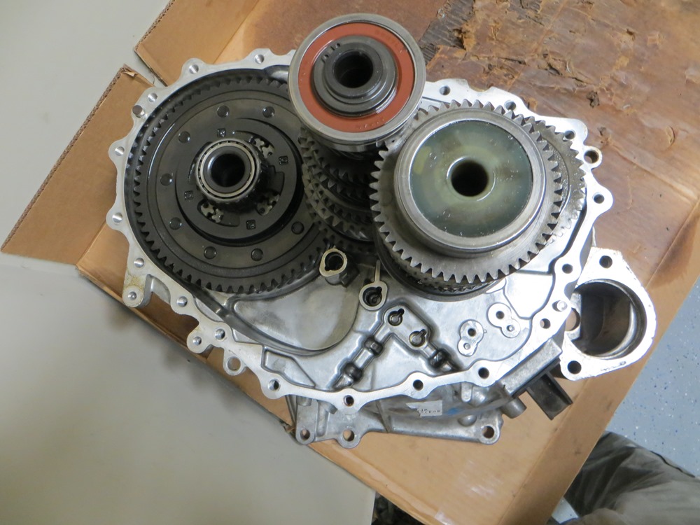
Maxima – Gear Stacks and Differential

SpecV – Gear Stacks and Differential

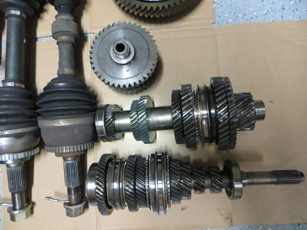
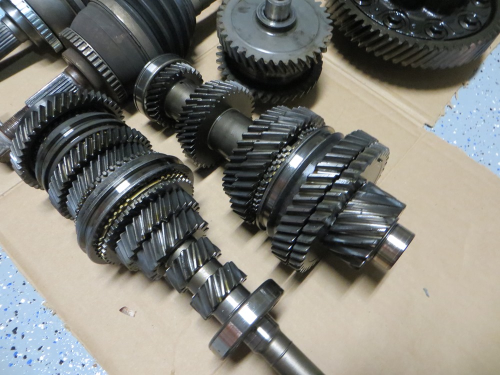
Maxima – Input, Main, & Reverse Shafts and Axels

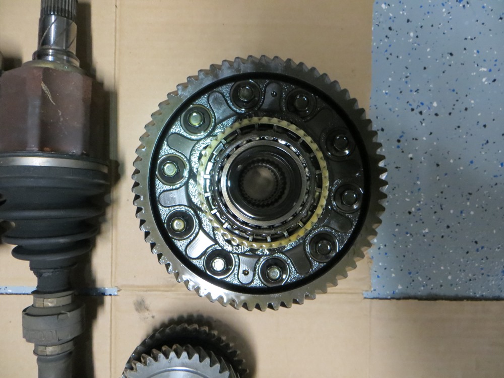
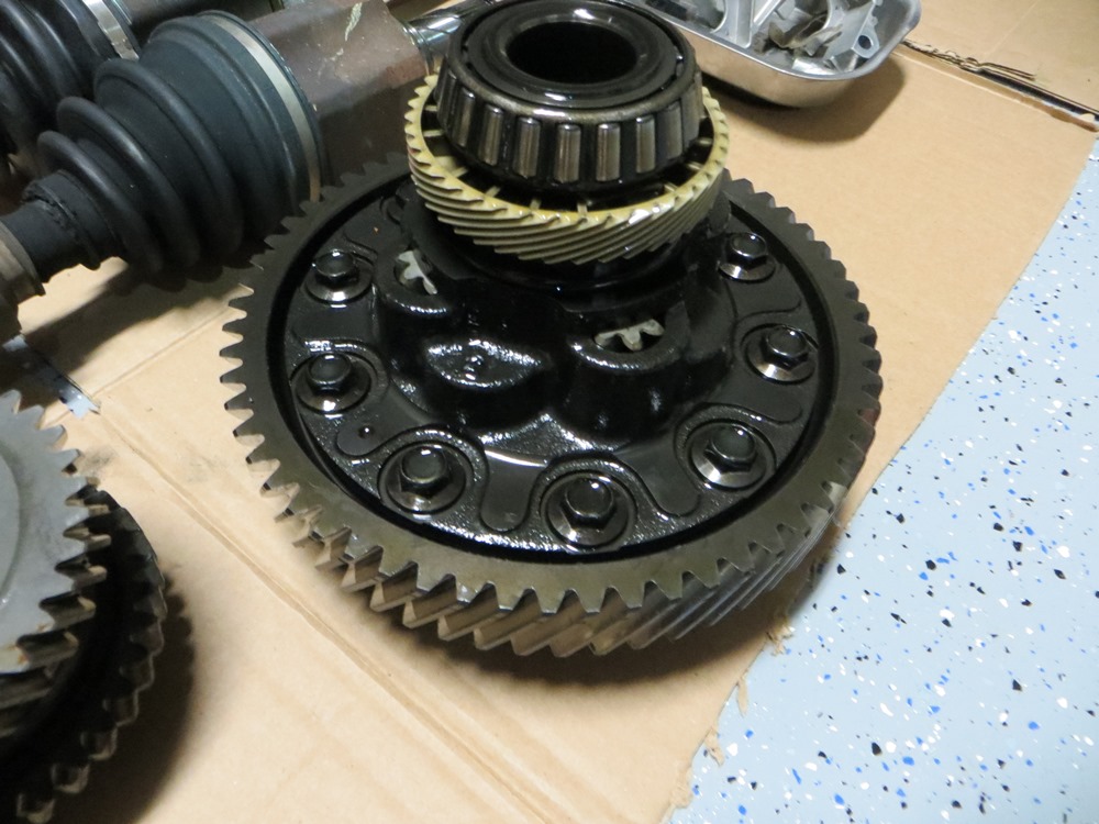
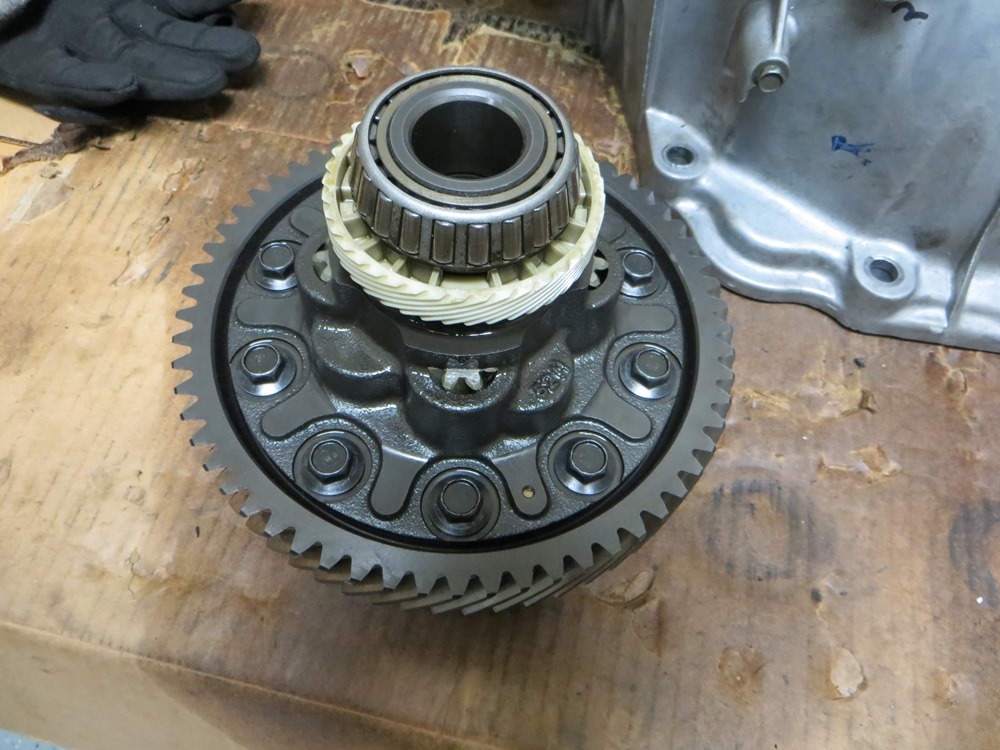
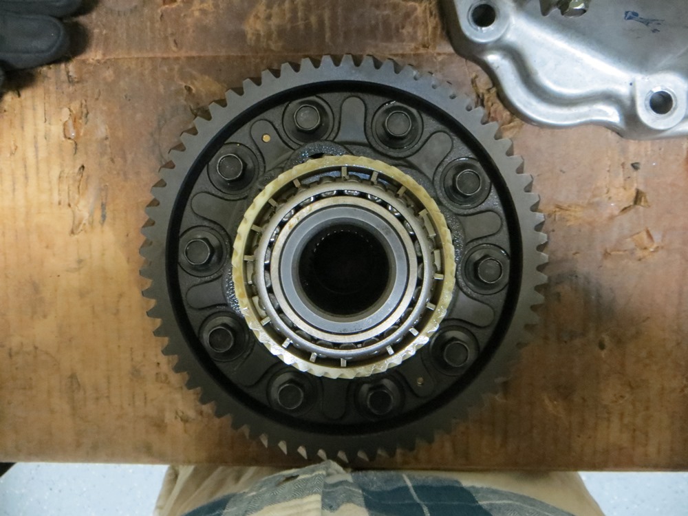
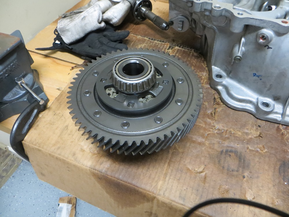
Maxima – Final Drive & HLSD

SpecV – Final Drive and HLSD

SpecV – Reverse Gear Set

Cleaned Maxima Bellhousing (Used acetone and cloth)

Cleaned Differential Side of Bellhousing

Maxima Final Drive and HLSD from SpecV

SpecV Reverse Gear Set

SpecV Gear Stacks and Maxima Final Drive in Bellhousing

Maxima Final Drive Meshed with SpecV Mainshaft

SpecV Mainshaft Meshed with SpecV Input Shaft

SpecV Input Shaft Meshed with SpecV Reverse Gear Set

Detail SpecV Main and Input Shaft

SpecV 5th/6th Shifter Fork with Maxima 5th/6th Shifter Fork Rod Detail

The SpecV 5th/6th Shifter Fork Rod had a pretty significant burr on it, and wouldn’t actuate properly. So I used the Maxima version.

SpecV Check Ball and Spacer for 5th/6th Rod

SpecV 1st through 4th Shifter Fork with SpecV Rod Detail

SpecV 1st/2nd Shifter Fork Detail

SpecV Reverse Bracket Detail

SpecV Reverse Shifter Fork Detail

SpecV Reverse Tilt Mechanism Assembly

SpecV Check Ball and Spacer for Reverse Rod Mechanism

Fully Assembled SpecV Guts and Transaxel Case on Maxima Bellhousing

SpecV Shifting Mechanism

Fully Assembled Transmission on Hoist

Loading

Member Credit: DaBoxSE

So my buddy and I did and overhaul last week on my car…I finally replaced my grinding transmission, rear main seal and replaced the Clutch. I wanted to put in something better than the stock maxima clutch because I thought it would be pretty weak. Also because I’ve had an Exedy Stage 1 in my 93 VE and loved it. As an alternative to the expensive Stage clutches for the 5.5 gen, I ordered a 350Z clutch from Dave B and prayed it would install no problem. Low and behold, it bolted right up. After putting the car back together, our first start caused a loud knocking sound…We couldn’t explain it, because he had done a ton of other work to the car including removing the Upper oil pan to install the front and rear seals. The noise went away eventually and now it doesn’t make a sound. Very strange.

I gotta say, the 350Z clutch is great! I love it. The pedal is much lighter in feel than the stock maxima clutch, and when engaging it bites, yet smoothly with almost no chatter. I didn’t have to adjust the pedal or anything. The engaging spot is right in the lower middle. The car just feels like it grabs effortlessly and with the cleaned out oil pan, intake manifold and new iridium plugs, the car feels like new. I’m definitely impressed.

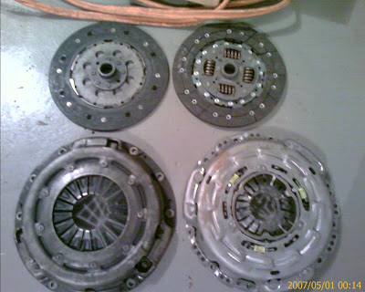
Stock on the Left and 350Z on right:

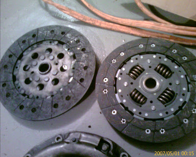
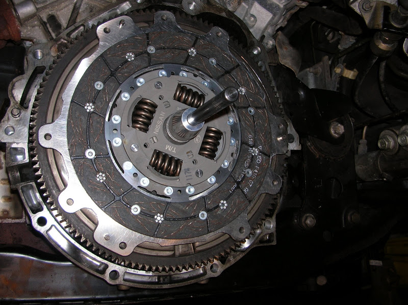
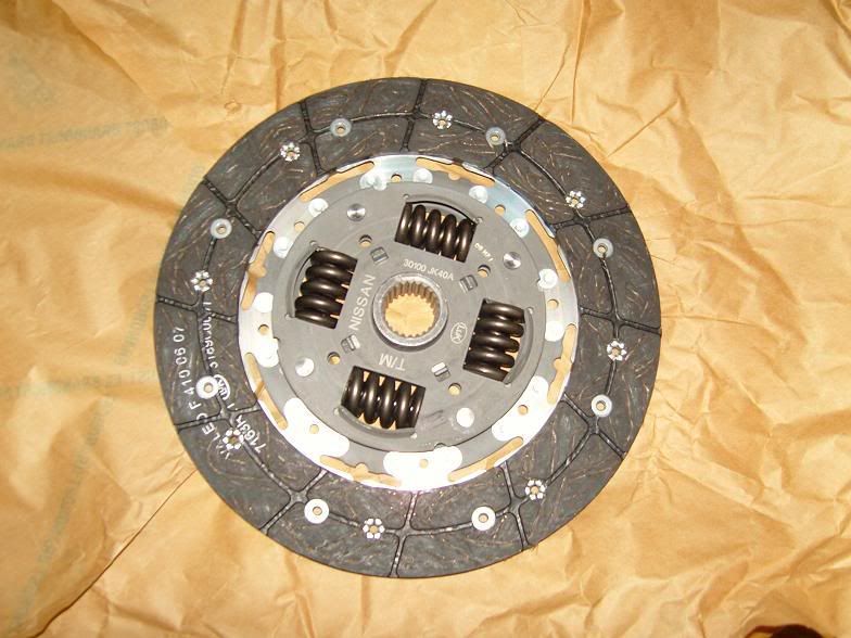
Friction Discs (notice how much heavier duty it is)

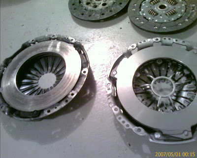
Pressure Plates (they weigh about the same too)

350Z Friction Disc

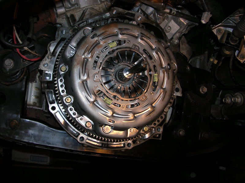
Pressure Plate Installed

“new” 03 6spd HLSD Transmission – Tried to get an 04, but none available in the time frame I needed it

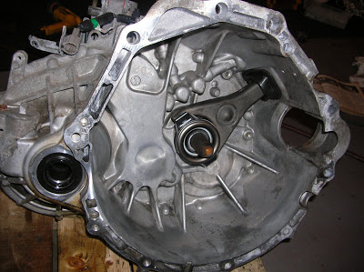
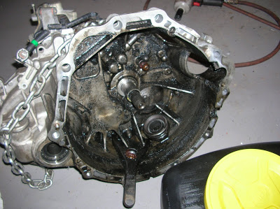
“old” 02 6spd HLSD Transmission – Can you believe this thing was still drivable. (Yes that’s a mix or gear fluid, motor oil and crap)

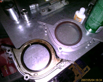
Rear Main Seal

Additional Insight from Member qnpark8282

I recently installed an HR clutch with Fidanza flywheel. So not only regular 350z clutch fits the HR clutch fits also. The clutch is very very light compared to stock and engages 10x smoother than stock.

Loading

Member Credit:  bigfatty

I have been getting a few PMs on this from time to time, but most questions have been answered somewhere in this thread, take some time and read because there is alot of good info in here from people other than me. I swapped only two coils in Jan of 2006 and through Oct 2007 have not had a single problem with any additional coils. If you can isolate the bad coil, why replace all 6?

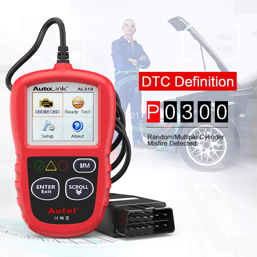
Sooooooo, I had the frigging SES, TCS, SLIP lights which any 5th gen owner should now know is code P1320, which means, drum roll please, Bad Ignition Coil. I was also luckily enough not just to have code once, but twice and also to have a code P0300, which is multiple misfires. I was able to get the codes pulled for free from my Autozone and so I started my quest to fix my car.

Some background info: The original coils from Nissan are garbage and Nissan knows this, yet they have chosen to do nothing about it. They did however update the coils with “newer” ones with a gray dot, that were supposed to be awesome. Well I open my hood, take off the cover and guess what, all my coils have gray dots. So I guess that blows that idea up. I bought my car in 2003 with 80k in miles from Woodfield Nissan in Illinois. So at some point in time they had already been replaced.

Ok, back to my test, I donated to Maxima.org so I could search and spent a night reading about just bad coils. The general consensus is that you should replace all 6 when one goes bad. The rough best price was about $300 for all six. The only problem is that I have this in my life right now that causes me to be short on money.

So after reading, I found a few things that will help in changing just the bad coils as I have done. I can not take credit for this info as pretty much all of it has been tried before, I am just trying to make it as easy as possible for everyone else.

Step #1 – Autozone

You may be lucky enough to have an additional code stored in your cars computer. If you have code P1320 with any P0301, P0302, P0303, P0304, P0305 or P0306, that is a misfire on specific cylinder. You now know which one is bad just replace that one, see the pics below on how to remove the coil.

Step 2 – Unplug coil one at a time

Remove your cover by taking the four bolts off your cover, you will need a 4mm allen wrench.

This test will only work if your engine is running really bad idle. If your SES/TCS/SLIP only come on when your engine is under load this test will not work, skip to step 3. My engine was running really rough even at idle, so I started to unplug the coils on at a time. Just squeeze the clip and pull, it will come off.

The first one I tried cylinder #2, when unplugged, made no difference at all in how the engine ran. SO I instantly knew that one was bad. If your coil is good you engine will bog down and almost stall, as you are basically removing a running cylinder. Do this one at a time until you find the one, that when removed, your engine does not seem to run any rougher.

Step 3 – Testing the resistance

You will need a multimeter to do this. I have had mine for a while and it worked fine for this. Its nothing big, and you can pick mine up at Sears for only $19.99. Remove all your coils.

The front three coils are right there held in by one 10mm bolt each. Unplug the clip, remove the bolt and pull. The coil will come right out.

Loading

Member Credit: maxiiiboy

Symptom (when turning the ignition switch to START)

Likely Cause

No Crank, No Nothing (not even dashboard lights) If the car starts with a boost, then the battery is bad. If not, suspect the ignition switch, the battery cables, fuses, or ground/power distribution.
No Crank, just a Faint Click Bad PNP switch, or Clutch Interlock, or Inhibitor Relay or fuse #20 (AT) or fuse #21 (M/T), both in the Fuse Block.
No Crank, but the Starter Clicks or Spins very fast Bad starter or starter solenoid
Cranks But No Start (starter cranks, but the engine does not fire up) If the red secuirty light is ON during cranking, then this is a NATS problem. Otherwise, bad Camshaft Sensor, or bad ENG CONT1 fuse (in Fusible Link and Fuse Box), or bad/no fuel delivery.
Engine Starts, then Dies Bad MAF, IACV, Cam/Crank sensors, Coils, or Injectors stuck flooding.


Fuse/Relay Box Locations:

  • Fuse Block (J/B): Lower dash panel, by driver’s left hand
  • Fusible Link and Fuse Box: Engine compartment, driver side, next/left to battery
  • Relay Box 1: Engine compartment, pasenger-side, next to P/S
  • Relay Box 2: Just behind front driver-side light

Loading

Member Credit: Metal Maxima

This is the second section of my electrical system upgrade. You can read the first part, how to upgrade the OEM ground wire, here.

This how-to will be covering the details on how to perform the upgrade known as the ‘Big Three’. Essentially, it will yield the following:

1) Reduced dimming and smaller voltage drops
2) More stable voltage and better current flow
3) Less strain on your vehicle’s charging system

The BIG THREE consists of:

(1) Battery negative to chassis
(2) Alternator to battery positive
(3) Engine Block to chassis

…it essentially does the same thing as a conventional grounding kit, however, it does so in a different fashion. I am not a big fan of grounding kits as I prefer this method. People will argue this one way or another, but I swear by this. So, let’s get started!

TOOLS/SUPPLIES

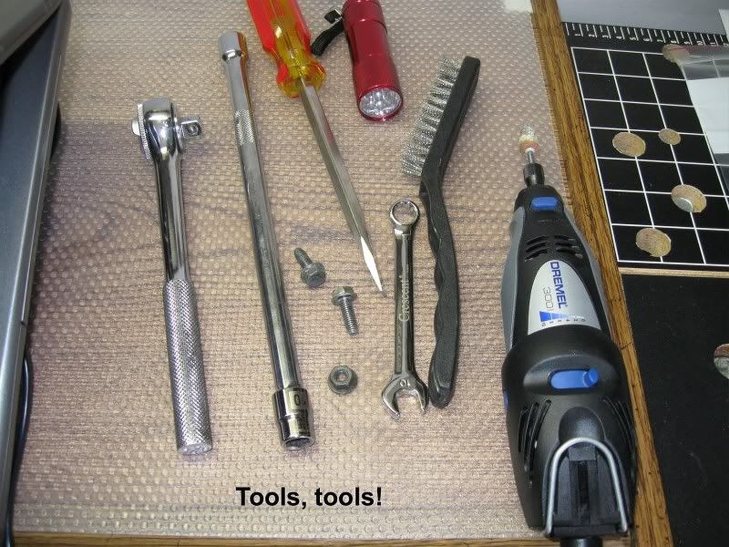
  • 10mm Socket
  • 12mm Socket
  • Ratchet
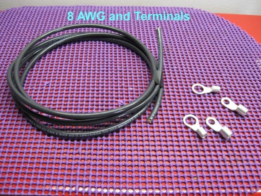
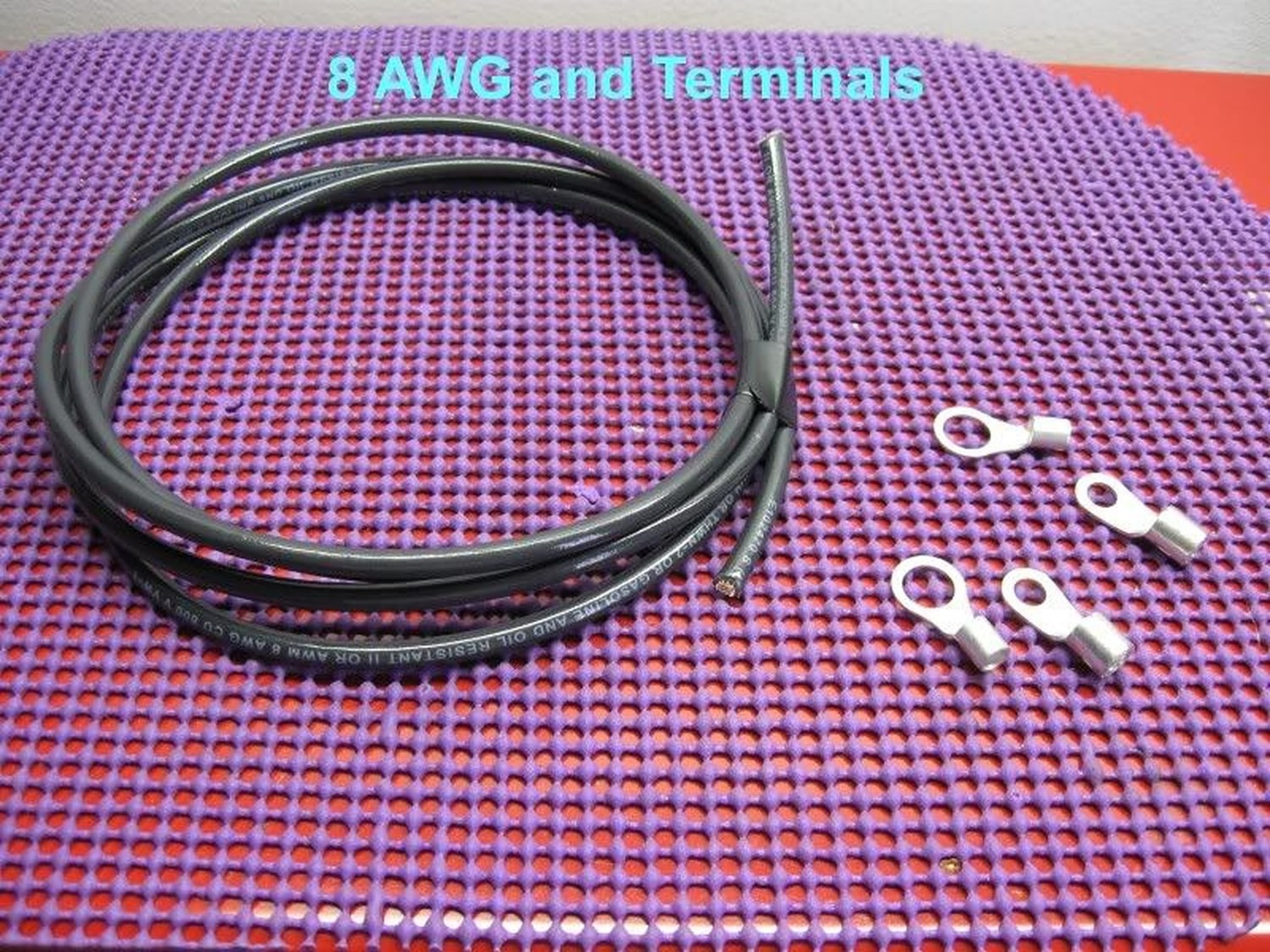
  • 10ft. of 1/0AWG Power Cable
  • 3 1/0AWG Ring Terminals
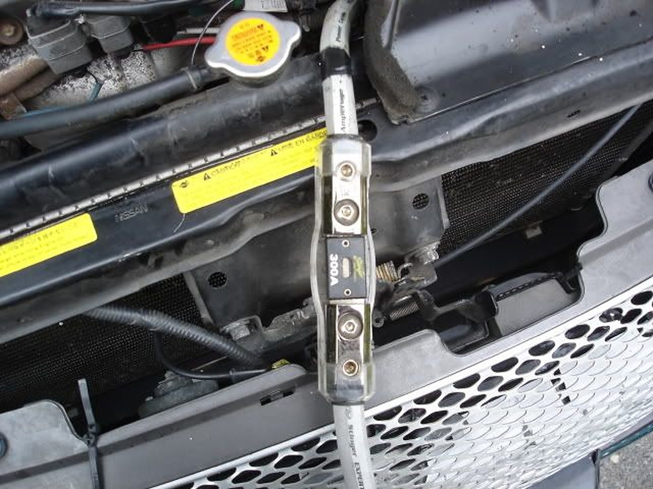
  • 1 1/0AWG Fuse Terminal w/ 300-amp fuse

STEP I – BATTERY NEGATIVE TO CHASSIS
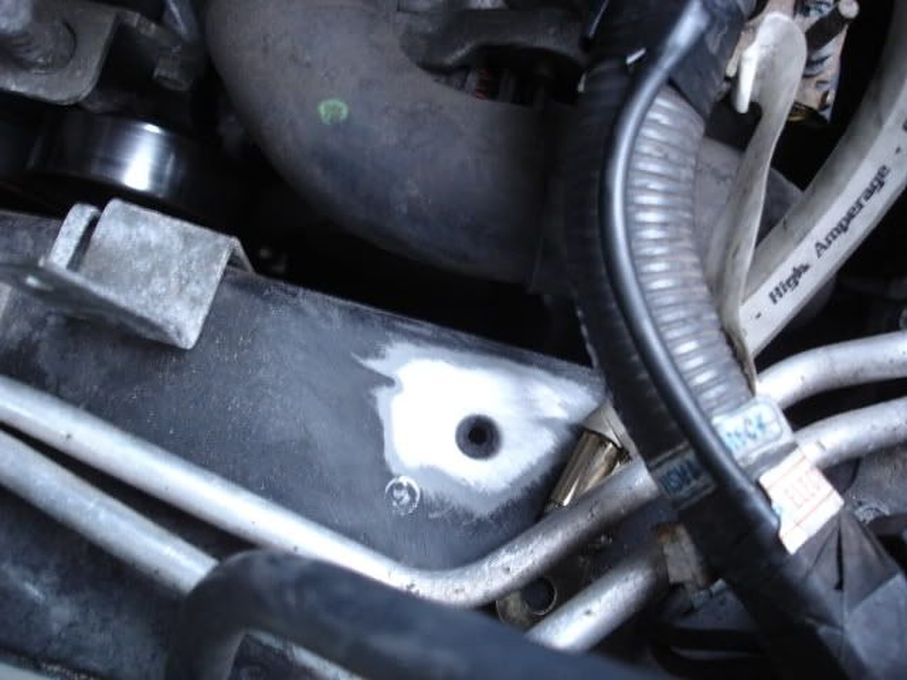
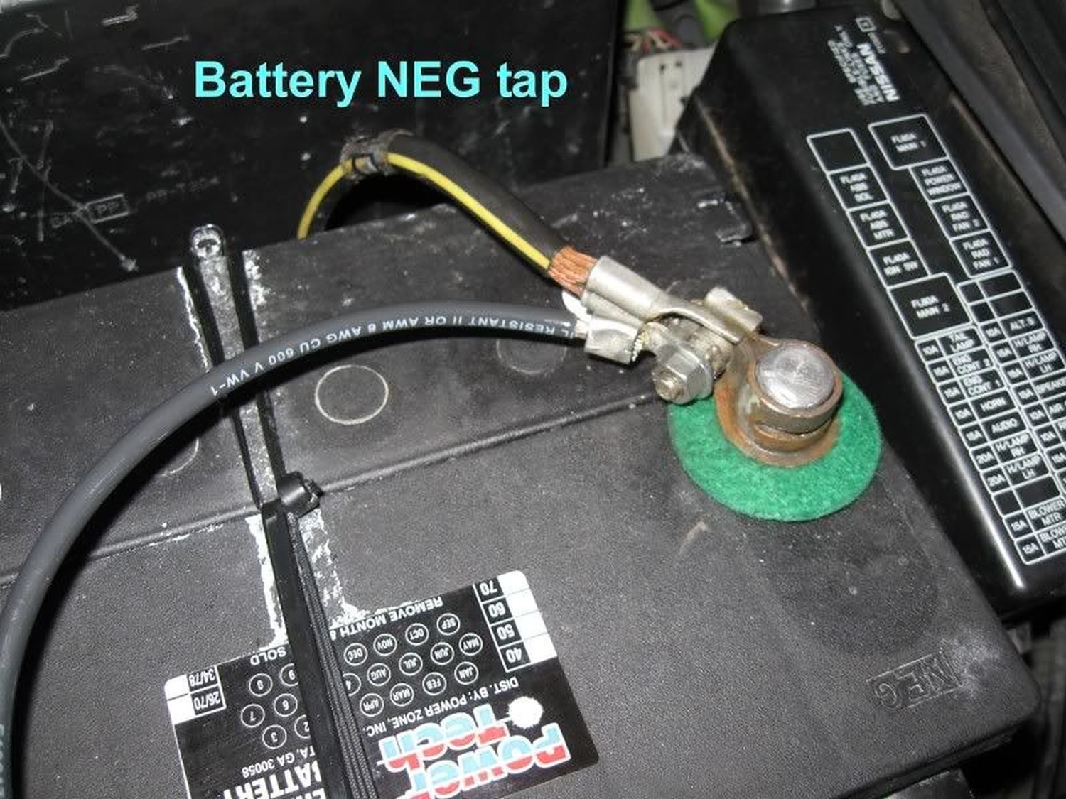
Simple enough. We are going to be making an attachment from the negative terminal of the battery to the chassis. If you peek behind the battery you will see a good place to plant the wire.

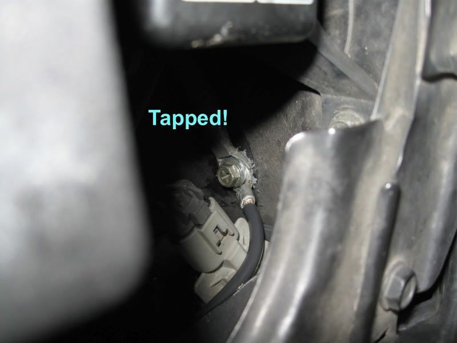
Remove the bolt with your 10mm socket and sand away the spot to bare steel. After that, attach about a 1-ft. length of wire to one of your terminals, crimp, and bolt everything back together.

STEP II – BATTERY POSITIVE TO ALTERNATOR POST

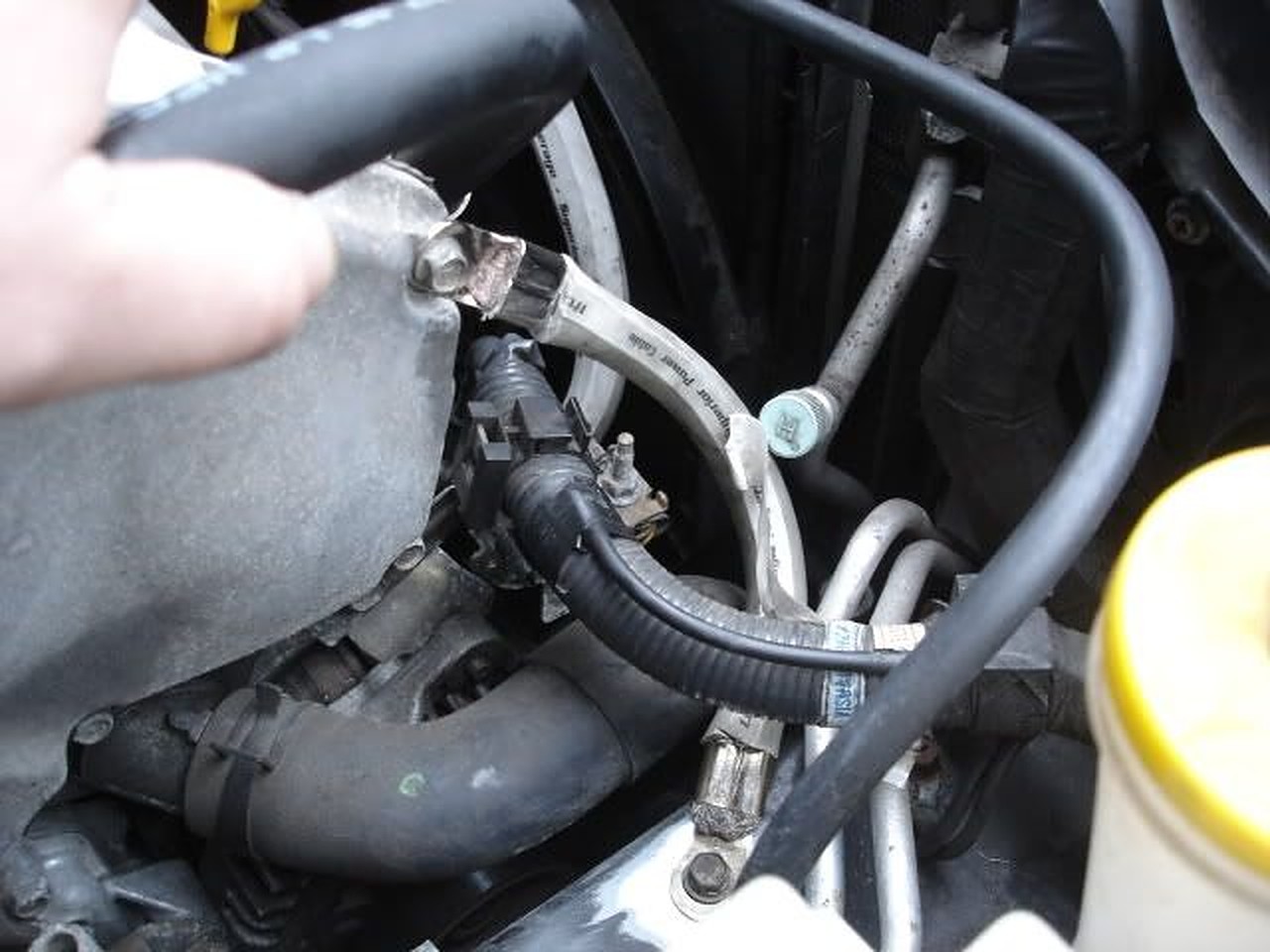
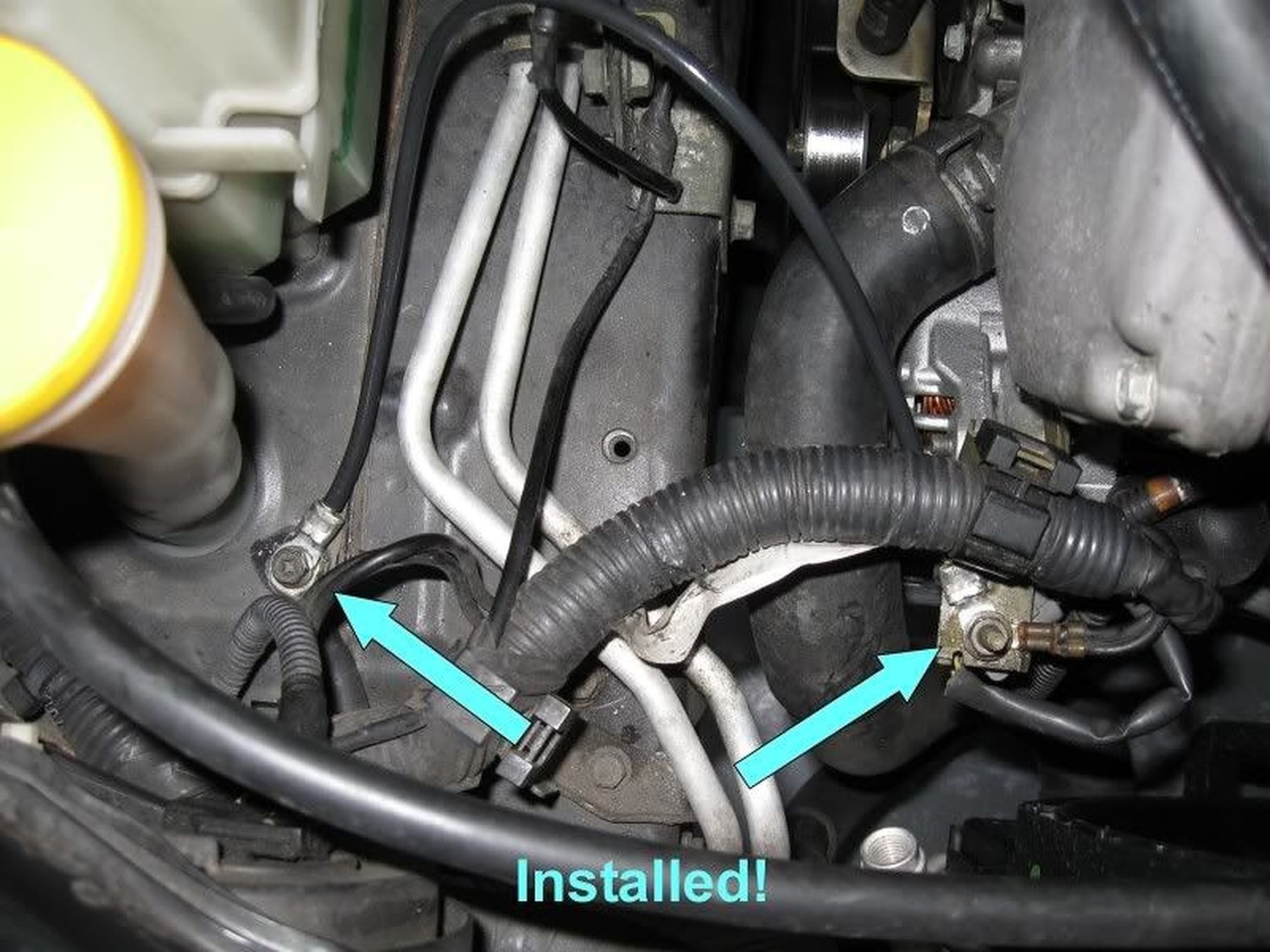
Alright, this one is a bit more tricky. You are going to need about 5ft of wire split into two equal 2.5ft. lengths. We are going to be attaching the wire to the battery positive to a fuse terminal, then fuse terminal to alternator post. You can find the alternator just to the outside end of the engine block on the passenger side. Look for a rubber boot covering a bolt. That’s your alternator post. We’ll start there. Remove the bolt using a 12mm socket.

Attach one crimped end of the 1/0AWG wire to the bolt, then screw everything back together.

Take the lead attached to the alt. post and run this to the fuse. Take the other length of wire and run this from the opposite end of the fuse and lead it to the battery. We’re almost done!

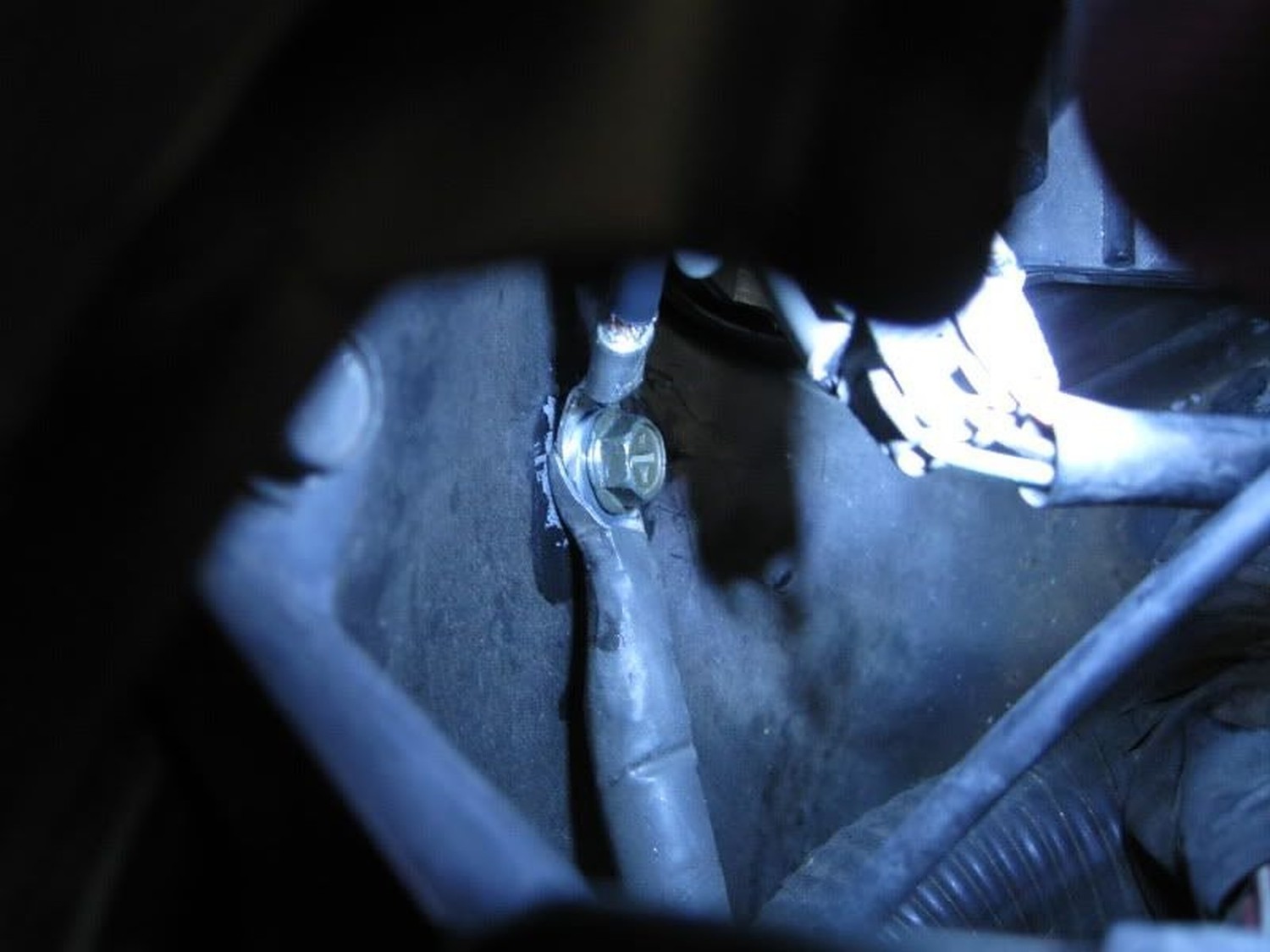
STEP III – ENGINE BLOCK TO CHASSIS

The final step is simple enough. Start off by locating a spot where you want to land the lead on the chassis. I chose an empty bolt hole located by the engine block. Sand away as we have done before.

Next, simply ground this to the engine block. I chose one of the 10mm bolts located on the side of the block. You can choose just about anywhere on the block; for instance, you will see two grounding points on top of the block. Golden rule with grounding wires is to keep them as short as possible, so just keep that in mind when doing this…

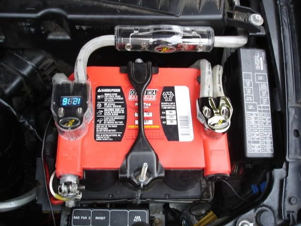
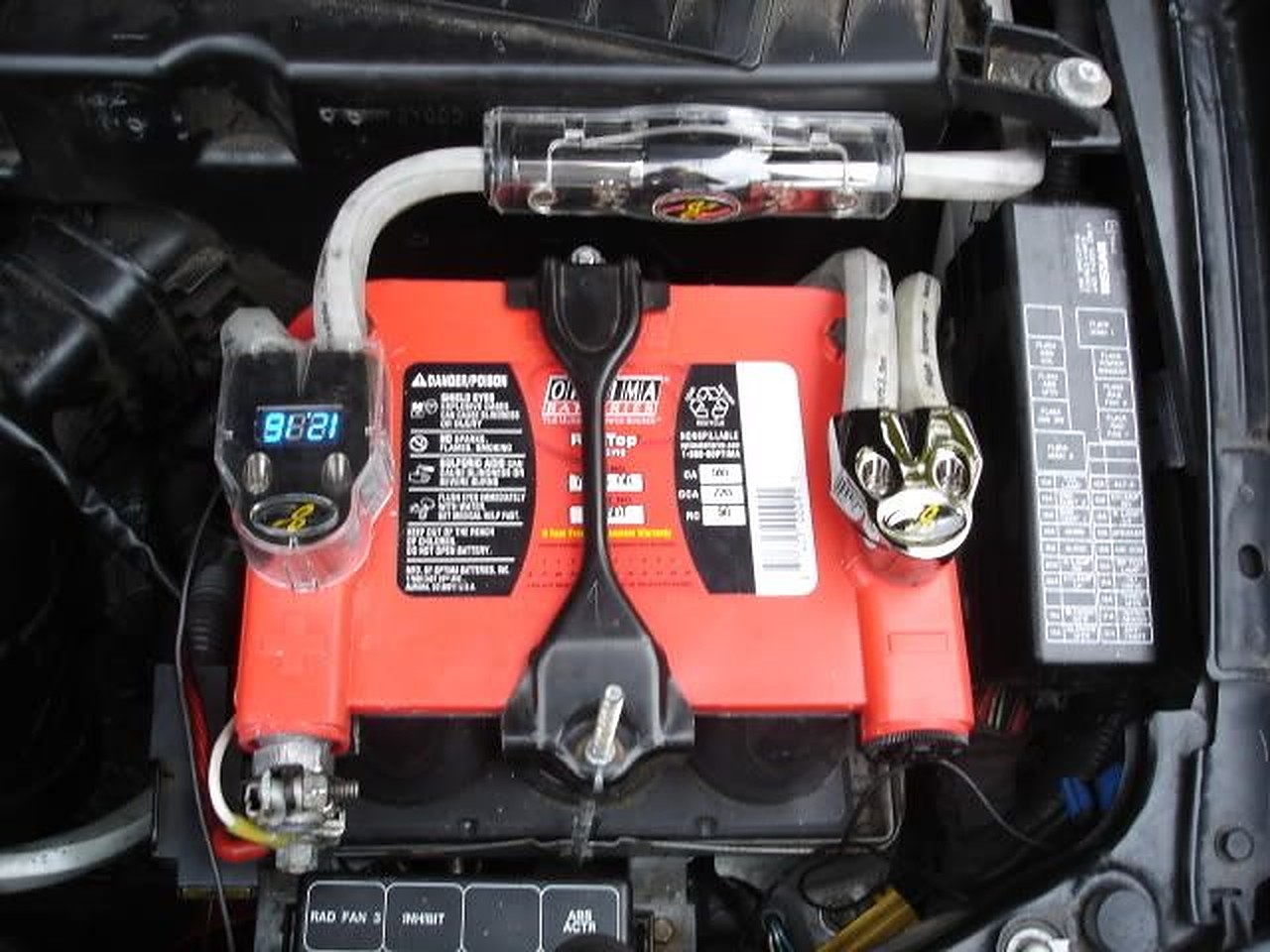
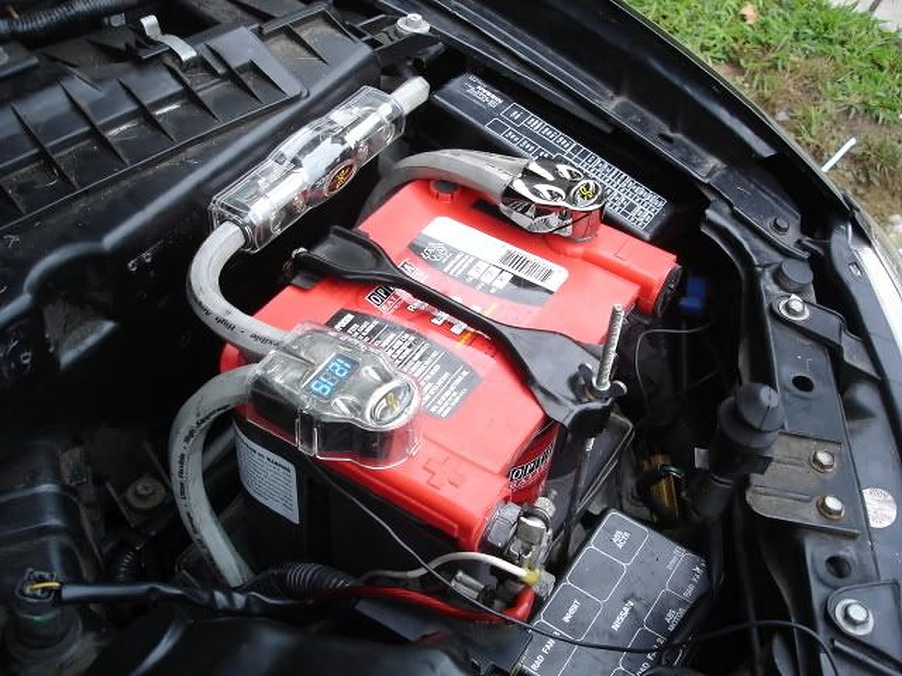
…and now you’re done! Here’s a shot of the battery when all is said and done…pretty bada’ss if I say so myself!

Loading

Member Credit: maxiiiboy (Vol.4, Spring 2017)

Summary

The 5th Generation Maxima is a very reliable car – if you know how to maintain it. The problem is that the car suffers from a few design defects that can make it expensive to maintain. For example, a worn-out engine mount may damage the Engine Control Unit (ECU) resulting in a major inconvenience and a dealer repair bill of $2,000-$4,000. Other actuators may fail with similar effect, sometimes repeatedly.

This note describes these problems and the remedies for eliminating them. The remedies are inexpensive and easy to do. If you own a 5-Gen Maxima, I strongly suggest that you do the following as soon as you can:

  • Implement “Coolant Bypass”, or replace your Idle Air Control Valve (IACV), or both.
  • If your car has an Automatic Transmission, then disconnect your two electronic engine mounts, both front, and rear.
  • Replace fuse #58 (15A, labeled ENG CONT1) in “Fusible Link and Fuse Box” by the battery with a 7.5A fuse.

Do the above even if your car experiences no problems at this time. If your car already experiences problems such as P0505 or damaged ECU, then read this document before attempting any repairs.

The above instructions may not make much sense unless you understand what the problem is. The next section describes the problem, and the subsequent one explains the remedies in more detail. If you own a 5.5-Gen Maxima, keep reading but you can dismiss the IACV issue – your car does not have an IACV to worry about.

Problem Description

The fundamental problem is that in the 5-Gen Maxima the Engine Control Unit (ECU) is not properly shielded from the failures of some components it controls. For example, we know that the ECU can be damaged by a) Failed/shorted IACV, and b) Failed/shorted Electronic Engine Mount. There are also some reasons to suspect that failure or misadjustment of the TPS (Throttle Position Sensor) may have a similar impact; I am still investigating.

How the IACV Fails

Most often, the IACV fails after the engine coolant1 shorts the wiring in its stepper motor. There is an O-ring gasket that should prevent the coolant from getting into the IACV, but after 10-15 years, it tends to fail. I suspect that there are other reasons why the IACV fails. For example, the thermo-valve inside the IACV may get stuck, or there is an intake leak; the IACV then tries to correct and eventually fails. The bottom line is that IACV failures (code P0505) are reasonably common and that they have disastrous consequences.

1 Engine coolant circulates through the Throttle Body and IACV to eliminate potential starting problems in cold weather. However, this seems unnecessary as the TB/IACV is nicely hidden between the two engine banks. There are multiple posts on maxima.org that confirm that there are no starting problems with coolant bypass, even in Minnesota winters.

Poor Fusing Protection of the ECU: When the IACV Wiring Fails and Shorts, 15A Current Flows Through the IACV and Damages the ECU
Figure 1

Figure 1 illustrates how the damage occurs. With a healthy IACV, the resistance of each IACV half-coil is 22 Ohms. Together with other factors this limits the maximum current through each half-coil to 0.5-1.5 Amp, and to a maximum of about 3-3.5 Amps through each of the two ECU ports and the STA509A transistor behind each port.

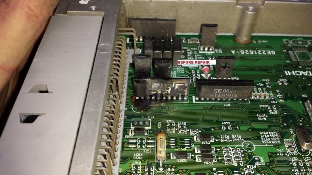
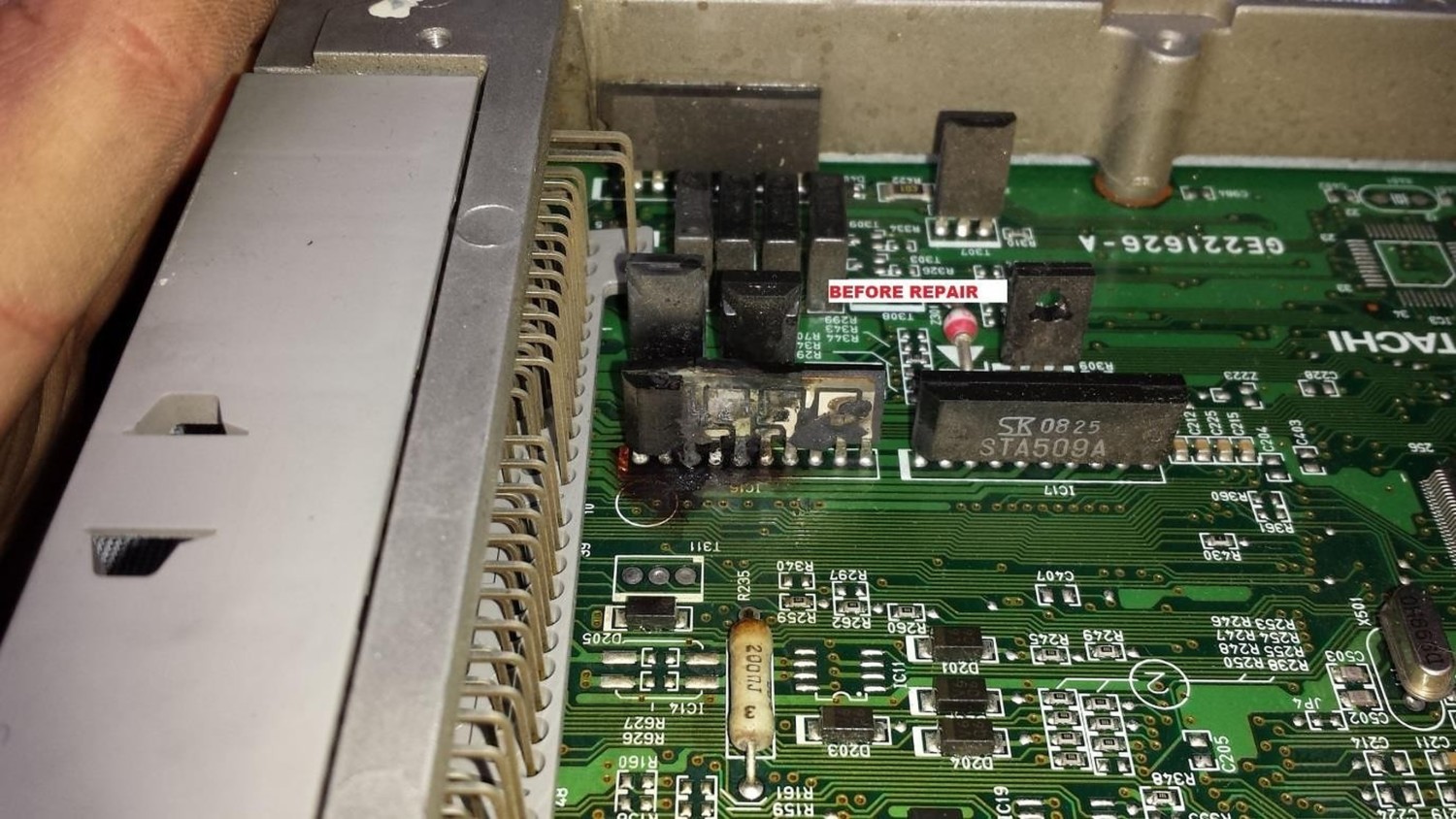
When the coolant eats up the insulation, the coil shorts, and the resulting current – up to the 15A limit imposed by fuse #58 – will flow through the IACV and “fry” the ECU. The 15A fuse should blow out, but usually the STA509 driver transistor in the ECU burns first, sometimes taking adjacent components with it. Appendix A shows how a damaged ECU looks like.

The horror story does not end here. Typically, the result is that both the IACV and the ECU are damaged. If the owner replaces just one of the two parts (say, just the ECU), he will find out that his new ECU is immediately damaged by the IACV he hasn’t replaced yet!! Even Nissan dealers are known to have made this mistake! The bottom line is: Make sure both parts are OK before replacing either!

Failure of the Electronic Engine Mount

5-Gen Maximas equipped with an Automatic Transmission have two Electronic Engine Mounts (Rear by the firewall, and Front by the radiator). Figure 2 shows the wiring schematic for these two mounts. Again, failure of either mount can damage the ECU in the same manner that the failure of an IACV can.

Poor Fusing Protection of the ECU: When an Electronic Mount Fails and Shorts, a 15A Current Flows Through the Mount and Burns the ECU Figure 2.

Each electronic mount has two states – Firm and Soft. Normally, the ECU puts the mount into the soft state at low RPMs (below 1000 RPM) and into the Firm state when the engine runs above 1,000 RPM. Disconnecting the mount eliminates the danger of ECU damage. It has no effect on the car (no codes or SES light) apart from occasional vibrations; more on that in the “remedies” section.

The Remedies

The ideal remedy would protect the ECU by using onboard fuses on all its critical inputs and outputs. However, I rejected this approach because of its risks: adding components to the ECU board and cutting traces or modifying wiring is just too dangerous for the average Maxima owner. For the same reason, I also rejected any solution that would cut/modify the Engine Room Harness.

This left me with the remedies described below. All of them have been successfully tested by the author.

Remedies for IACV Failures

There are three remedies that will reduce the probability of an IACV failure:

  1. Preventative IACV Replacement. It seems that most IACV’s fail at around 100-120k miles. To replace your IACV, you have to remove the Throttle Body and unscrew the four Phillips screws holding the IACV. This is not a pleasant task, as the screws tend to be frozen. Once the job is done, a new IACV (use OEM part only) should be good for another 100K miles or more.
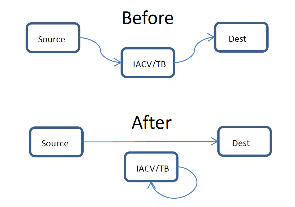
  2. Coolant Bypass. Coolant Bypass (see figure 3) eliminates the possibility that your engine coolant will eat on your IACV wiring. On a 2000 Maxima, the bypass requires no additional parts – neither hoses nor clamps – apart from a good set of hose pliers. The job can be done in about 5 minutes (excluding the access/re-assembly time), with the Throttle Body in place. When you do the bypass, remember to blow out any residual coolant so that the IACV is as dry as possible. Also note that in a departure from figure 3, you can completely remove the IACV “half-hose” leaving the two coolant orifices on the IACV open.

    Implementing Coolant Bypass: No Parts Required, Just Move the Hoses Around Figure 3.
  3. ENG CONT1 Fuse Replacement. Replacing fuse #58 (15A, labeled ENG CONT1 in the Fusible Box next to the battery) with a 7.5A fuse provides an improvement over the OEM setup. Be aware that the 7.5A fuse does not guarantee protection: The STA509A transistor can be damaged by any current exceeding 3A (see footnote2), but the fuse needs to be larger than 3A because there are multiple devices on it3. However, going with the smaller 7.5A fuse increases the probability that the fuse will blow before the STA509 transistor will, and it decreases the probability of large-scale damage – such as burned traces – to the ECU board itself! The fuse costs a few cents (http://www.delcity.net/catalogdetails?item=77075) and can be swapped in/out in 30 seconds.Important Note: If/when the 7.5A fuse blows, you need to treat it as a signal that your IACV has failed. You should check the IACV, and if indeed shorted, replace it.

To summarize, there is no reason not to do #3. The same applies to #2. So, the question is: After you are done with (#3 + #2), should you do #1? I have done it eventually when my IACV experienced other problems (needed cleaning).

Isolating Engine Mount Failures

Only AT Maximas have Electronic Engine Mounts. For these cars, the following remedies exist:

  1. Disconnect Electronic Mounts. Disconnecting the Electronic Mounts is the quickest solution. The connectors are brown, each with 3 conductors, and both are located close to the AT dipstick. Depending on whether the mount is disconnected in Firm or Soft state, you may experience the following side-effects:
    A: Mount in Firm State: Some/minor vibration when the engine idles.
    B: Mount in Soft State: Minor in-line vibration between 1,800 and 2,400 RPM, when the engine pulls, only under some conditions, depending on how you step on the gas. I suggest you do not worry about the Firm/Soft state too much: once disconnected, the electronic pump within the mount will stop firming up the mount, and the mount is bound to become (semi)Soft no matter how you disconnect it.
  2. Replace with Manual Mounts. Using the mounts from MT Maxima is possible. It is also relatively easy as the MT mount is a direct fit. This is the preferred solution when the original mount is physically worn out. The side-effects are the same as in (1a) above.
  3. Add a Fuse to the Mount. It is physically possible to add a fuse to your Electronic Mount. The logical place is at connector terminal #3 where the battery power comes in (see figure 2). However, this would be best done when the mount is being replaced. Otherwise, #4 below may be a better choice.
  4. Non-ECU Control of Electronic Mounts. Yet another solution is to keep your Electronic Mounts, but take the ECU out of the loop. One would have to implement a semi-intelligent control that is both fuse-protected and decoupled from the ECU (or any other expensive part). I am tinkering with this solution.

2 Each of the two IACV half-coils is powered by a single STA509A transistor within the ECU. Each transistor can withstand a maximum current of 3A in steady-state mode and 6A in pulse mode. The desired protection would insert two fuses – one into the lead/connector port #2, and one into port #5 of the IACV (see figure 1). It would allow for proper fuse sizing, somewhere in the 3A-6A range for each fuse.

3 Powered off this fuse are multiple subsystems: IACV, EGRC1, MAFS, TP/SW, and others.

Repairing vs. Replacing Your ECU

ECU failures are annoying and expensive. When the ECU can’t be repaired, the only solution is to purchase a “new”4 ECU and then tow the car to the dealer to have the keys reprogrammed. In some places, you may be able to find a locksmith that can do this task but it is not clear this is always possible. The key point is: because of the hassles associated with key reprogramming, you always want to repair your ECU rather than replacing it.

4 “New” means “appropriate ECU of the same type, in working order

The following outfits provide ECU repair and are considered reputable:

Reputation questioned:  Circuit Board Medics.

Acknowledgments

Directly or indirectly, many members of maxima.org (and Nakis in particular) contributed to this note. I have learned a lot from other MAXIMA.ORG members. This note is an attempt to re-pay some of my debt.

Appendix A – How a Damaged ECU Looks Like

The above pictures are just examples. Not all damaged ECUs look like this. Sometimes, a burning smell is the only indication.

Appendix B – Notes re. Improved Fusing

Existing fusing:

Fuse #58 covers, via ECM relay pins (#6, #7), the following: MAIN, MAFS, POS, EGRC1, EGVC/V, AAC/C, TP/SW, IGN/SG (acronyms from the FSM). From the circuit diagram, this is only:

  • IACV, EGR/C1, IGN/SG (Coils) – and nothing else; still, this is too much for a single fuse, so we must insert the fuse at F52 (the IACV connector)

Fuse #59 covers, via ECM Relay pins (#3, #5) the following: MAIN, MAFS, POS, EGRC1, EGVC/V, AAV/V, TP/SW, IGN/SG, EMNT, TPS, NONDTC, NATS. From the circuit diagram:

  • ECM pins 110+112, CPS-POS, MAF, TPS, EMNT,

Solution requirements:

  • Should be switched by ECU/other relays
  • Avoid cutting the harness!

Possible implementations:

  1. Insert two fuses at IACV connector (F52). Insert them serially into IACV pins/leads #2 and #5. After splicing, bring the four “fusing” wires to some convenient place where the fuses would be placed. Use 3A fuses.
  2. New Power Circuit for IACV. Bring two new power lines to the IACV (use fuse adapters to create them). Fuse them either after, or before, the ECU Relay. The latter case will only work if the ECIU relay has two spare pin(s).
STA509A Datasheet:

http://www.datasheets360.com/part/detail/sta509a/-2407484356475109966/

Maximum current is 3A, max V is 47V

Loading

Member Credit: dustey

The Issue

I have been battling a cylinder 6 misfire (P0306) for many months now. I have spent a lot of time on this website researching, but I can’t seem to find anything that works.

The problem: Intermittent misfiring on cylinder 6 that will come and go. It can switch from misfiring to not misfiring instantly. No change due to driving conditions. It happens on the interstate at 70mph, in neighborhoods at 25mph, and at idle. Some days it runs great, only misfiring for a short time, other days its a battle all day long. Sometimes it accelerates just fine, other times it misfires all the way. The idle is fine. Although it may misfire, the idle stays very normal, with no fluctuation.

I have checked the easy stuff already:

I have done all of the above, and none have made any difference in the misfiring. Always on cylinder 6.

I, fortunately, know a tech at the local Nissan dealership who also tested the wiring harness and intake plenum with similar results. He also flashed my ECU. He is now saying it’s the ECU because none of the other things have fixed it. His cost on the ECU is $650!

I called David from SpeedometerRepairGuy.com and explained what I needed and he said the ECU rebuild he does for Maxima’s wouldn’t fix my misfiring (only fixes damage from a bad IACV), also stating he had never heard of this problem before. Again, I have no problem with my idle.

Not sure what to try next. A friend of mine suggested the fuel filter, but the Nissan tech was adamant that it couldn’t be the fuel filter, also citing its a “lifetime” part. Thought about just changing it, since it’s so cheap anyway.

Any other ideas of things I should try before getting a new (or used) ECU? I have already purchased one used ECU through car-parts.com and it was bad, so I am 1) trying to avoid the hassle of trying to find a good used ECU and 2) trying to avoid spending $650+ on a new ECU from Nissan. After all, at this point, I don’t know it’s a bad ECU, it’s by deduction that I/we think its the ECU.

I replaced the ECU with a reman unit from the dealership and had them install and reconfigure everything. (I did this as I pulled my then current ECU out and it was clear that water had gotten into the unit and there was corrosion on the board plus my buddy the Nissan tech is usually spot on.) Didn’t misfire for a day, but its back with vengeance now.

Since the posts above, I replaced the spark plugs again with OEMs (had Auotlites before), and today I switched coils between the bad 6th cylinder and a good cylinder (2), and it still continues to misfire and throw a P0306.

I just don’t understand why it would not misfire for 2 straight weeks when I replaced the fuel filter/strainer and then come back. Could it have something to do with fuel pressure? I mean, replacing the fuel filter/strainer does mess with the fuel pressure since you have to disconnect the lines and pull the fuse? I may be wrong, I am no mechanic…

What’s next? Switch out the injector again? I am second-guessing everything I have done now…

The Fix

To follow up on this thread, I checked the compression (dry) and it was 125 across the board. Low, but not inconsistent which is good. Despite the Nissan tech’s advice to not replace the fuel filter (strainer) since it’s a “lifetime” part, I did anyway because it was a $13 part, easy to do, and $13 isn’t a lot to take a chance on in case it does work. I did both the compression test and fuel filter last Thursday (8/19/10) and it hasn’t misfired since. Unbelievable.

It started doing it on Friday 9/3/10. It went 2 weeks without misfiring, and started back again. The frequency seems to be less, however, it is throwing the P0306 code again (same cylinder as before). Since the problem started however long ago, it hasn’t gone that long without misfiring. It leads me to believe that its fuel-related somehow.

A friend suggested that it may be caused by a dirty fuel tank… reasoning that it ran fine for 2 weeks with a brand new fuel filter until it reached the dirty stuff in the tank. It did start misfiring just after I had filled up at the gas station (waiting in line for the car wash at the same station, actually). I just find it hard to believe that a dirty tank could do that and cause the exact same cylinder to misfire, but stranger things have happened.

Well, I got it figured out. There is something loose or a bad connection with the actual connector on the wiring harness which connects to the coil pack. Me and a friend of mine just starting wiggling all of the wires we could find after determining that it had to be something electrical related. By moving the connector itself a hair this or that way, I could cause it to misfire and then stop. We rigged it up to hold its place where it’s not misfiring:

So far so good. It has misfired maybe once or twice in the last week but it was literally just ones or twice and then it would be fine.My mechanic buddy at the Nissan dealership is going to replace it when he can find a spare. I know what you are thinking… Shouldn’t I have noticed this a really long time ago? Well, in hindsight, yes of course. But, it was one of those things that I took for granted and looked past. I never considered it could be something like that…

Loading