This article will help you install Audi R8 Coil Packs on your VQ30DE. For those that don’t know, Audi coilpacks are stronger and better than Nissan coilpacks. They add better mpg and more HP/TQ. It works on bone stock vehicles or highly modified vehicles.
Nissan Coilpack only has 1 coil. Audi has 2 coils as you can see in the picture below. By having 2 coils it doubles the spark output and can easily handle spark blow out that turbocharged vehicles suffer from. Because it’s outer exterior has a metal body it can dissipate heat ALOT quicker than Nissan rubber which helps with heat cycling. It’s also cheaper than OEM Nissan Coilpacks.
The Audi R8 coil packs fit perfect on the front valve cover and do not require any modification. It will work fine even if you have NWP spacers installed on the front.
Rear Valve Cover
The rear valve cover requires some modification for a flush fit to ensure the R8 plug makes full contact with the spark plug. Since the coil packs now go further in…. they clear the manifold as well which requires no additional spacers.
Audi R8 Coil Pack Advantages:
50,000 volts compared to Nissans/Infiniti 30,000 volts.
Some measure it with Kv so Nissans coils put out 21Kv while VW coils put out 30Kv
Quicker Heat dissipation. (Because of its metal body construction it can quickly dissipate heat. Nissan OEM body is made out of rubber that isolates heat instead of disperses it.)
More complete burn of the fuel mixture compared to OEM Nissan which equals to better MPG.
Idle Stability Improved
NO CEL (Check Engine Lights)
BEST PART ABOUT THEM IS THEY ARE CHEAPER $$$ than Nissan OEM yet they are much better.
Looks 10000% Cooler than OEM Coilpacks
Now the coil packs price varies due to different name brands. They range from $132-$216 for a V6 engine. Below is the link of the coil packs below so you can see the prices and brands. Doesn’t matter which brand you use, I’ve tested them all and they all make the same exact power.
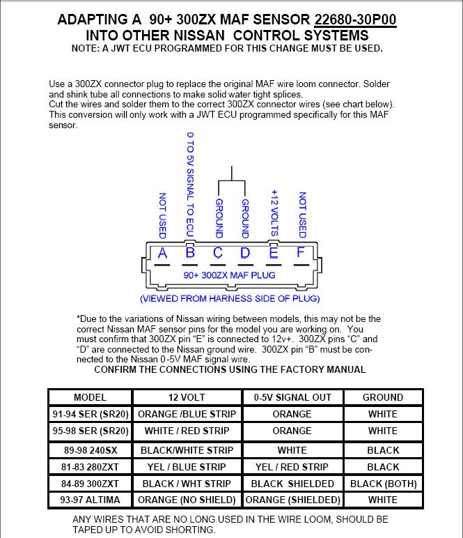
Z32 MAF Part Number: 22680-30P00 Tomei Z32 Airflow Meter Harness Part Number: 194002
The Z32 Mass Air Flow (MAF) sensor is great for turbo or supercharged setups. If you are not boosted then you do not need these. If you are boosted, the Z32 MAF allows you to measure more airflow into the engine than what the stock A32 MAF can. The Z32 MAF is calibrated for higher airflow and you can stay with an airflow referenced fuel metering system. The A32 MAF maxes out at an airflow equivalent to about 300HP and the Z32 MAF can meter about 500HP worth of air.
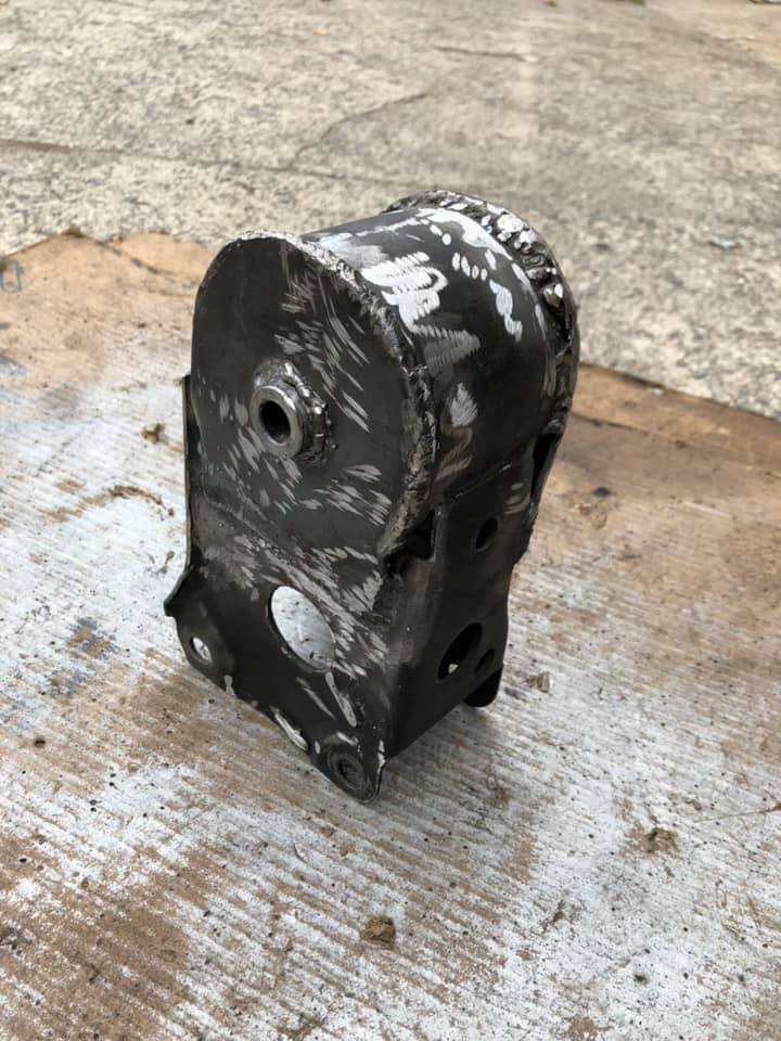
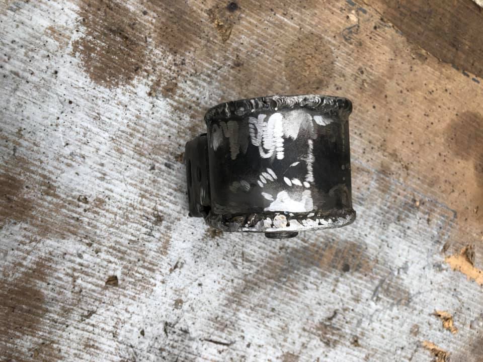
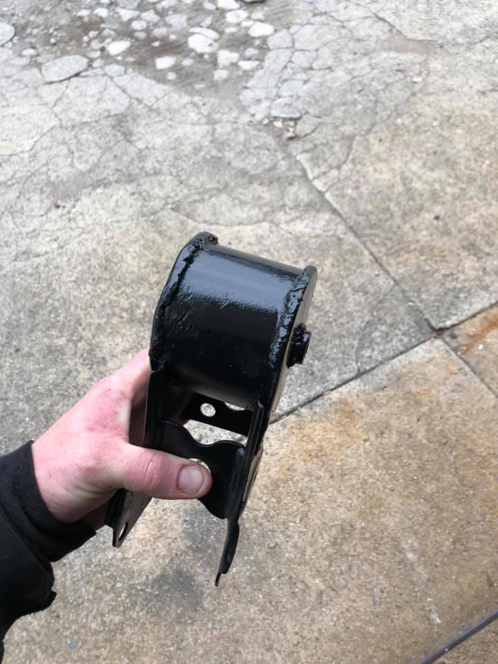
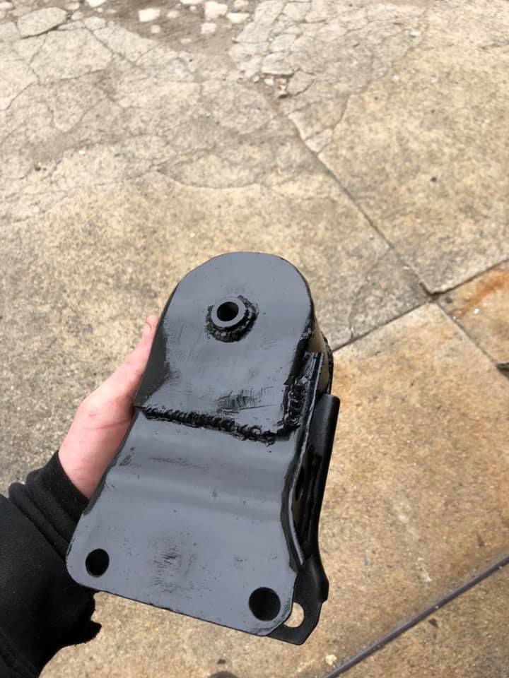
The J30 and the Z32 MAF both have the same sensor, just different harness connectors. The Z32 connector has two extra unused pins. Sometimes you can save money if the junkyard dealer doesn’t realize that the J30 MAF is the same as the Z32.
To simplify the installation, you can grab a Tomei Harness. The part number is 194002.
Z32 MAF Plug
A (No wire) = not used B (White) = A32 White (Signal Wire) C (Black) = A32 Black (Ground) D (Orange) = A32 Black (Ground) E (Black/White) = A32 Red (Power) F (No Wire) = not used
1995-1999 5thgen Maxima MAF Pinout
Pin 1: White = MAF signal (White) Pin 2: Ground (Black) Pin 3: +12v ( Red)
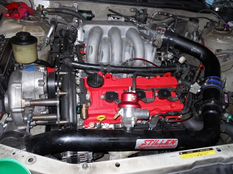
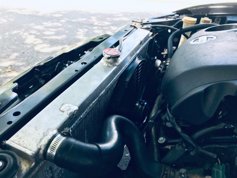
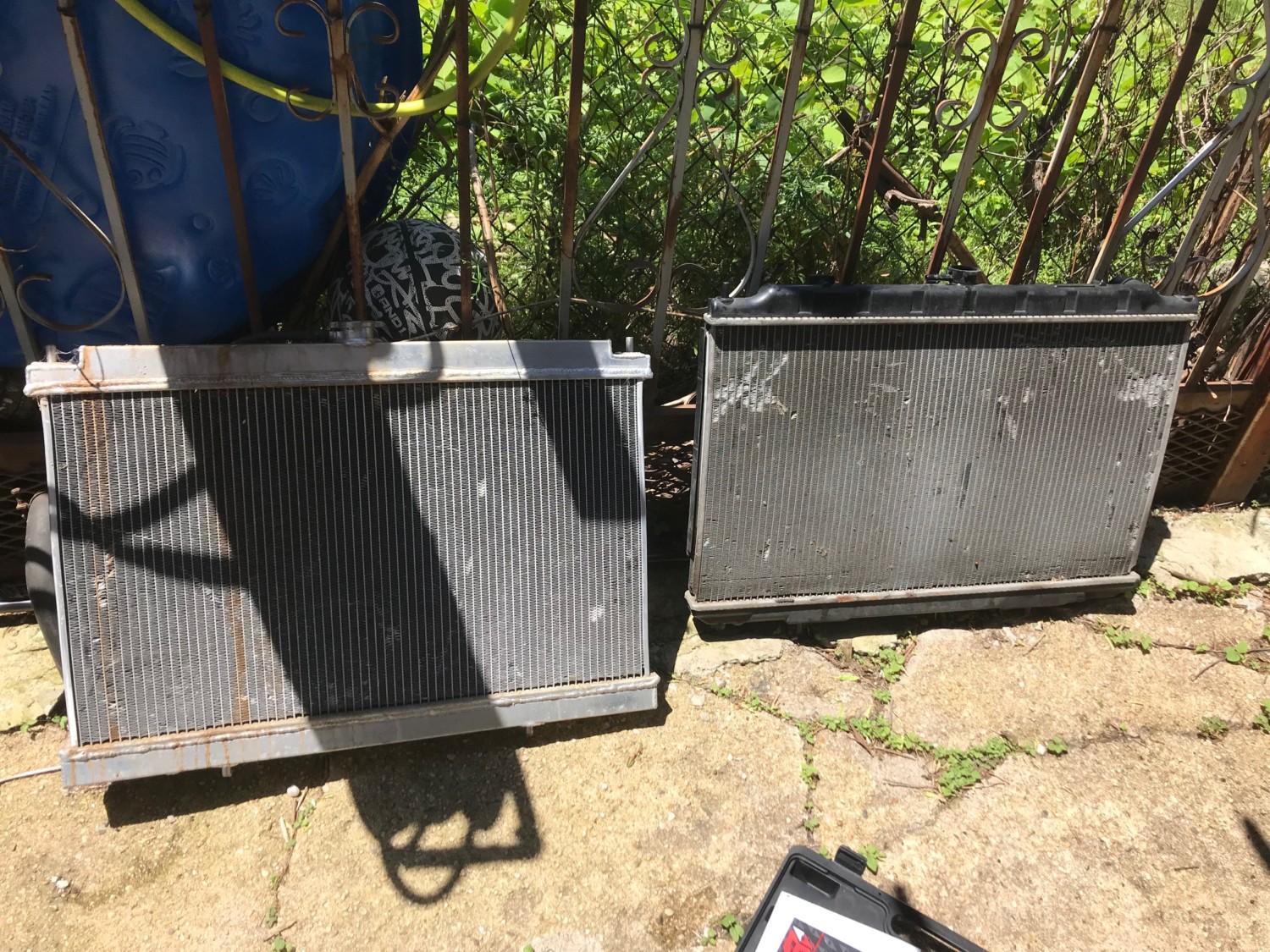
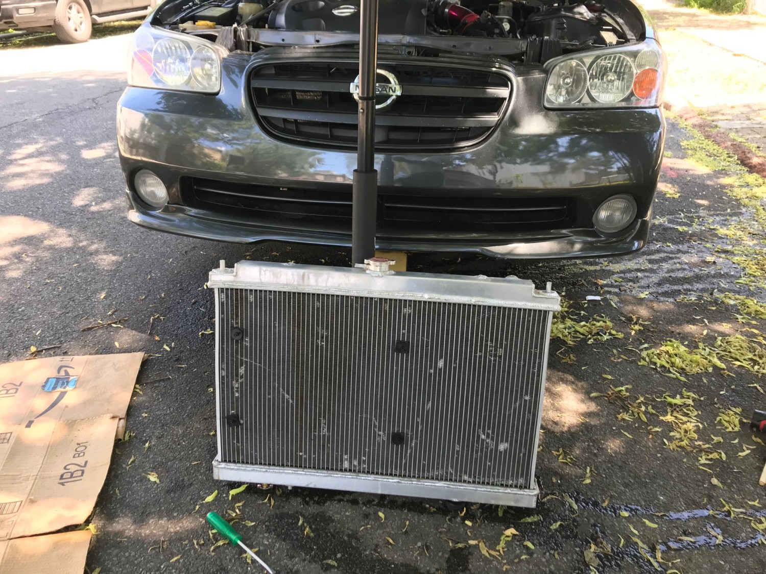
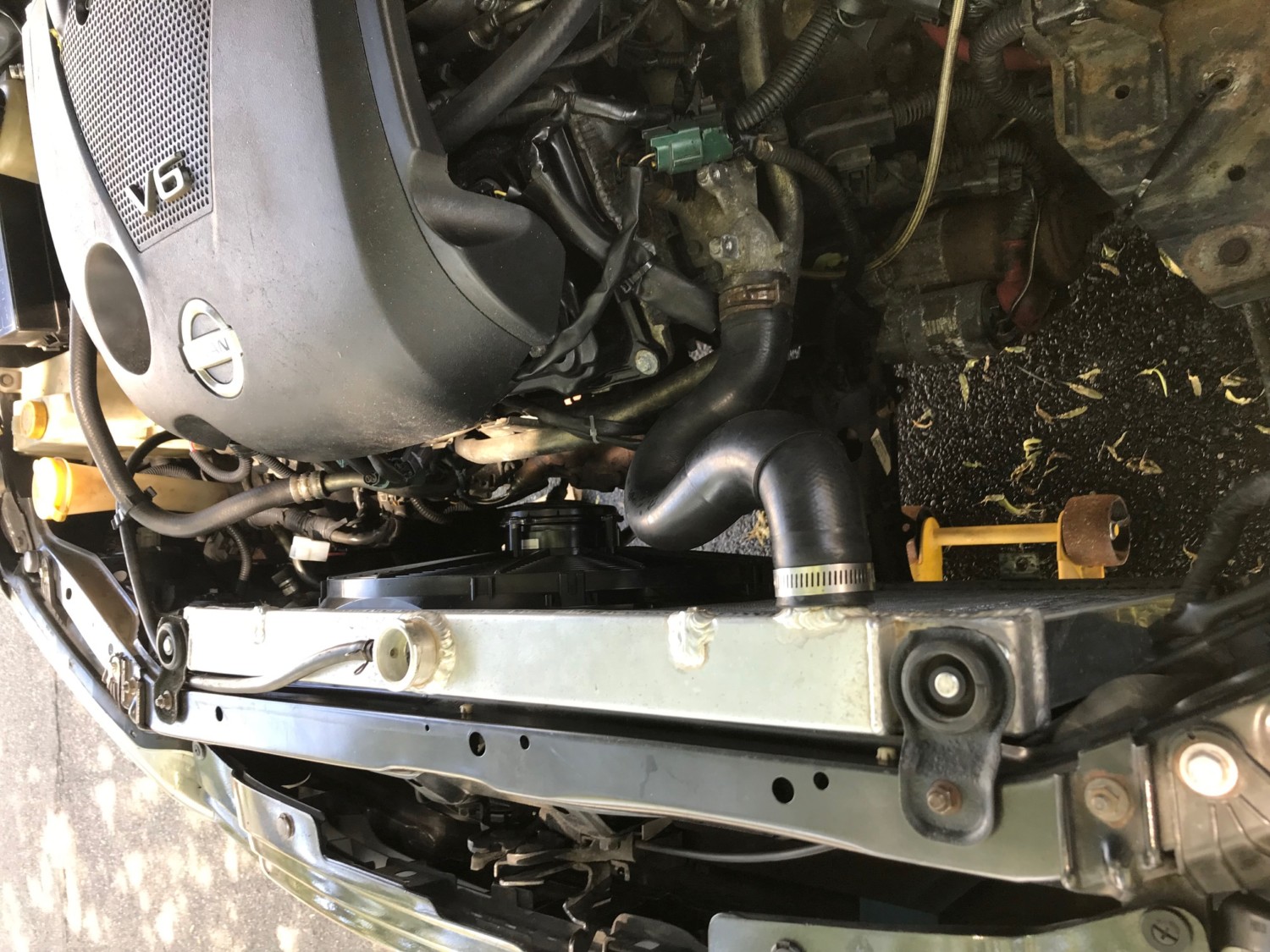
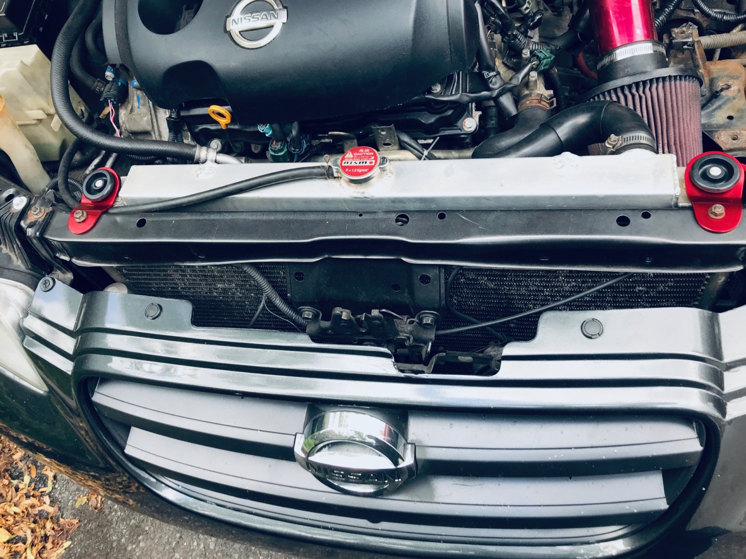
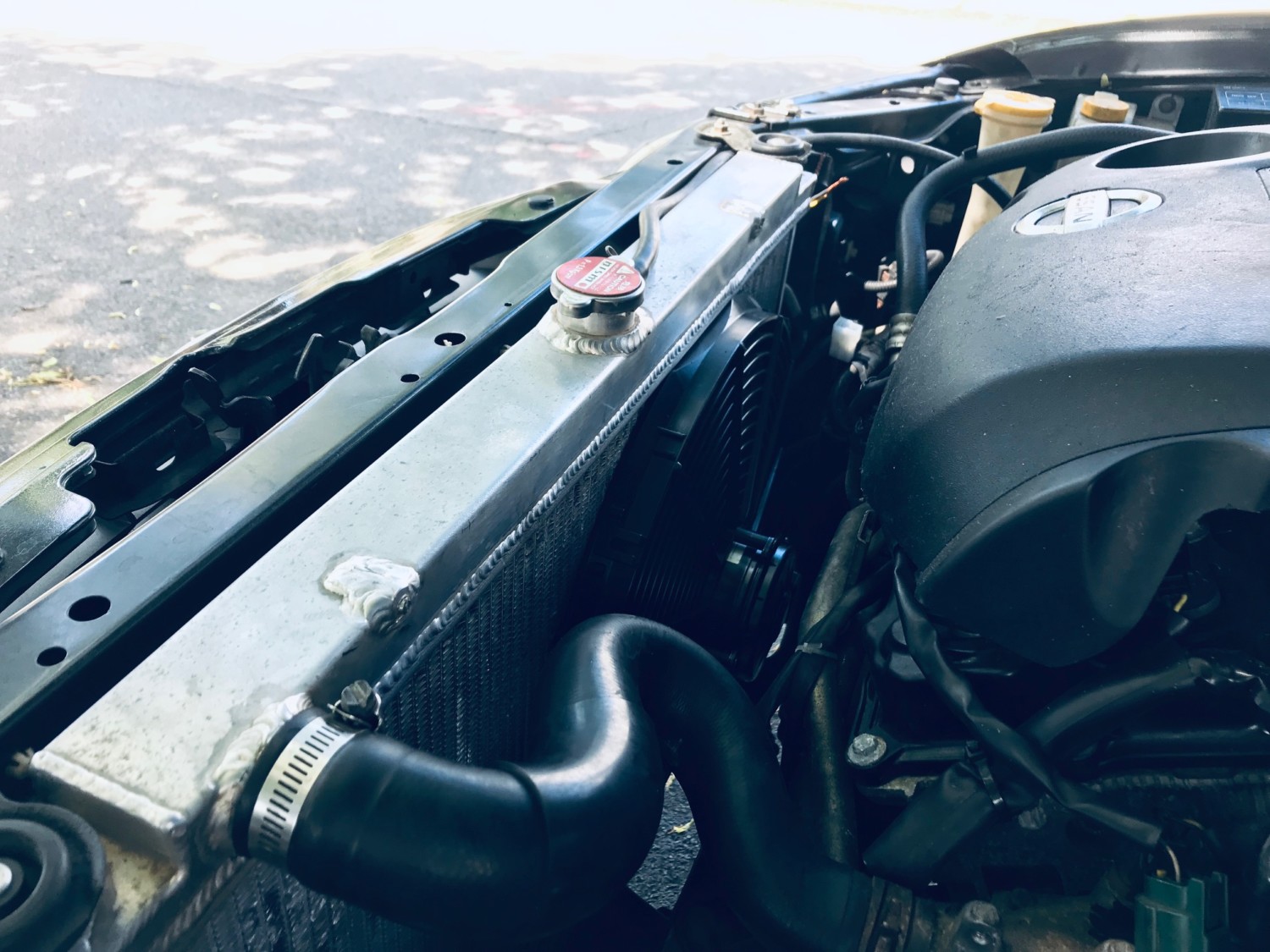
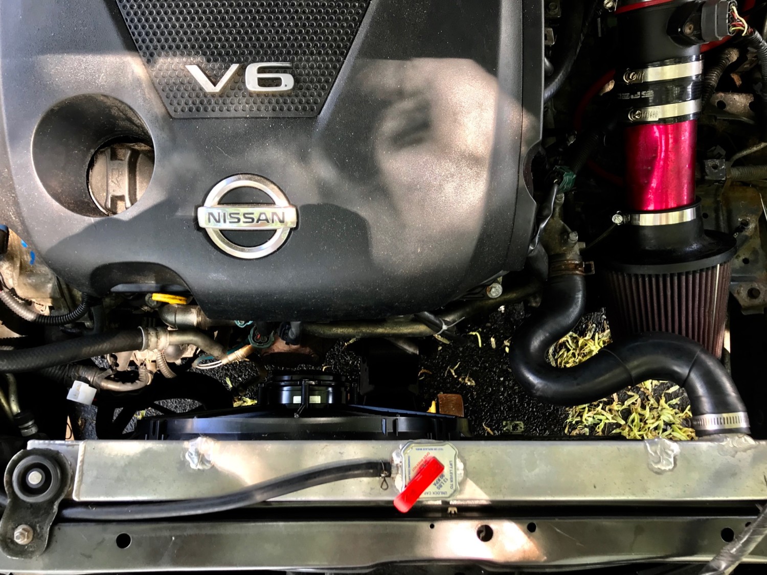
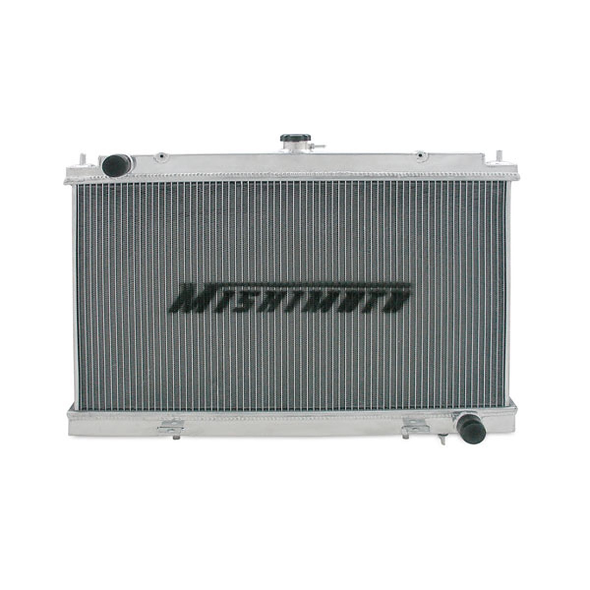
If you are tired of your OEM plastic radiator cracking or just simply looking for an upgrade, the 4thgen radiator is a very good option. It fits perfectly on the 2000-2003 5thgen and only costs around $100 bucks. The quality is great and equal to those of other known brands like Mishimoto and Megan (in my opinion). I have been running this radiator on my Supercharged 5thgen with no issues for years now. This post contains all the details you need to know.
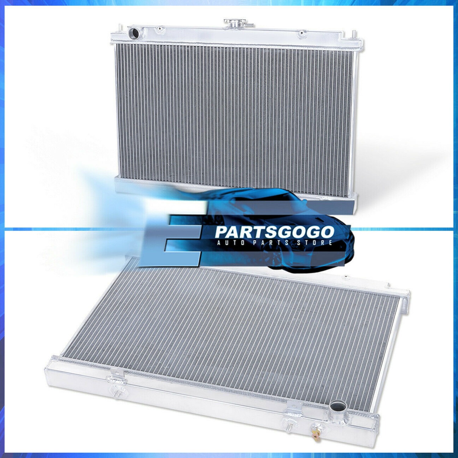
eBay Item Description: High Performance Engine Oil Cooling Aluminum Radiator For 95-99 Nissan Maxima Mt Price: $109.99 Order Link:https://www.ebay.com/itm/324093481879
Important Note for Automatic Transmission Owners
You will notice that most aluminum radiators say “Manual Transmission Only”. This is because the Automatics have a cooling hose that flows between the radiator to the transmission. You can easily purchase a transmission external oil cooler and you will be all set. One of the most commonly used brands is Hayden and you can find it any local parts store. Below are some reference photos. Here’s a link to a write-up which can be helpful: https://www.my4dsc.com/how-to-install-transmission-cooler/
Additional Item Details:
Full Aluminum Radiator
Made By OEM Approved & ISO Certified Manufacturers With Materials That Meets Or Exceeds Strict OEM Requirements
Improves Cooling by 35 – 45% Heat Radiation
Made of High Quality Full T-6061 Aluminum Construction
Super lightweight design help reduces the weight compared to the OEM radiator and helps eliminate plastic end tanks that will eventually leak.
Dual-core will have aluminum large rows allowing faster heat exchange and reduce the possibility of overheating.
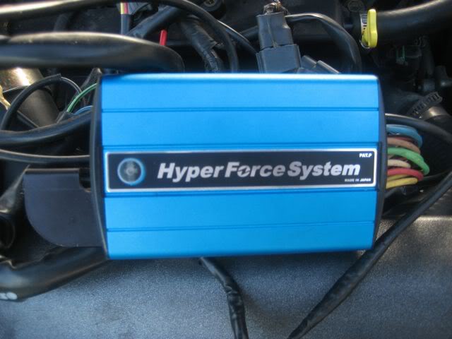
The Sun Auto Hyper force is an ignition enhancer, in which provides greater throttle response and smoother engine performance by providing optimal spark duration and maximum voltage output. This product is very effective at higher revs where a normal spark would diminish, specially on boosted 350Zs/ G35s. It prevents high rpm ignition miss that reduces peak power and the longer duration allows the Twin Power to improve lower RPM throttle response and torque.
The Sun Hyper Force system is the next generation high-efficiency ignition tuning and strengthening system. It works by absorbing all back electromotive force, which aids to improve plug voltage and promote complete combustion by producing higher coil efficiency. Also, the Sun Hyper Force System eliminates any ignition performance loss due to decreased electrical current under heavy throttle. Since ignition efficiency over the entire revolution range improves, available torque and acceleration response improves; this efficiency enhancement also contributes to better fuel efficiency and a reduction of harmful emission.
Features
Increased horsepower
Increased torque
Better gas mileage
Improved throttle response
Longer battery life
Improved battery efficiency
Reduced emissions
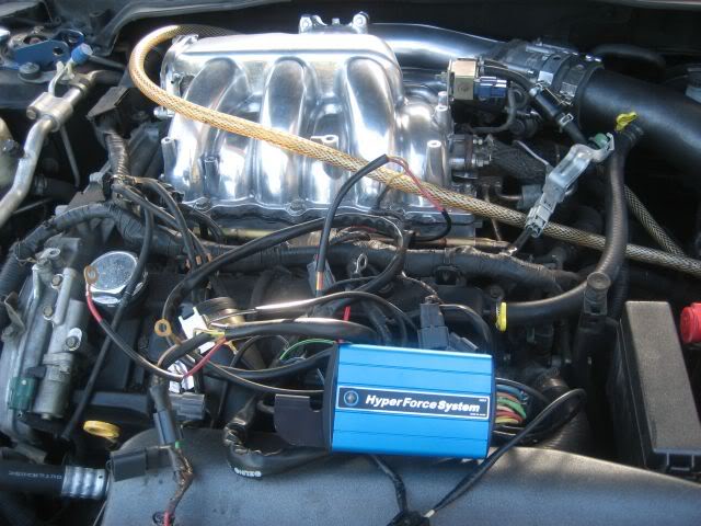
This is a plug and play system, you connect the plugs from the coilpacks into the harness and there is a plug there goes back into the coilpacks.
6 Ground wire and 1 positive to the battery from the Blue box.
It flashes Blue LED light so that you know everything is up and running.
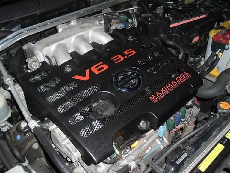
Uncovering the CF cover
After these it got really dark so i didn’t bother taking anymore pics, I need to clean up the wires and mount the box near the firewall , this system was design for the 350z but will work for our cars.
If you know how to do your own spacers or change your spark plugs you can do this upgrade. This is how I would rate the difficultly.
Hope this can help anyone that wants to use an aftermarket fuel gauge. May already be a write up on this but I couldn’t find it. I decided to go with aftermarket after not being able to find a cluster with one that actually works correctly.
Used one from Glowshift. Regardless of what gauge brand you use, results will be similar. After a few trials and error I got the new one working with no cel and gas lights on. I chose to mount the new gauge where the ashtray is. Didn’t take pics of how I wired power to it but I just used wire taps on the constant and switched ignition to the stereo.
Under the back seat I chose to just cut the green signal wire going to the fuel pump sending unit. With this wire not connected you will get a cel for high signal input. It uses a variable ground signal from the sending unit. You will also get the low gas warning light and dte will flash. I used a 47 ohm resistor and grounded the side going to the body harness and hooked the new gauge up to the side going to the pump. Ignore the butt connectors. This wasn’t the finished product. It was soldered after everything was working right.
If you ground the wire without the resistor, you will still get a CEL. After it’s all done with, my OEM gauge sits right above half and I have no CEL. You should be able to use any resistor between about 10 and 75 ohms. I opted for 47 OHM. Since it was in the middle of the resistance values of the sender. Last pic of where it sits with it all finished up. I’m happy with it.
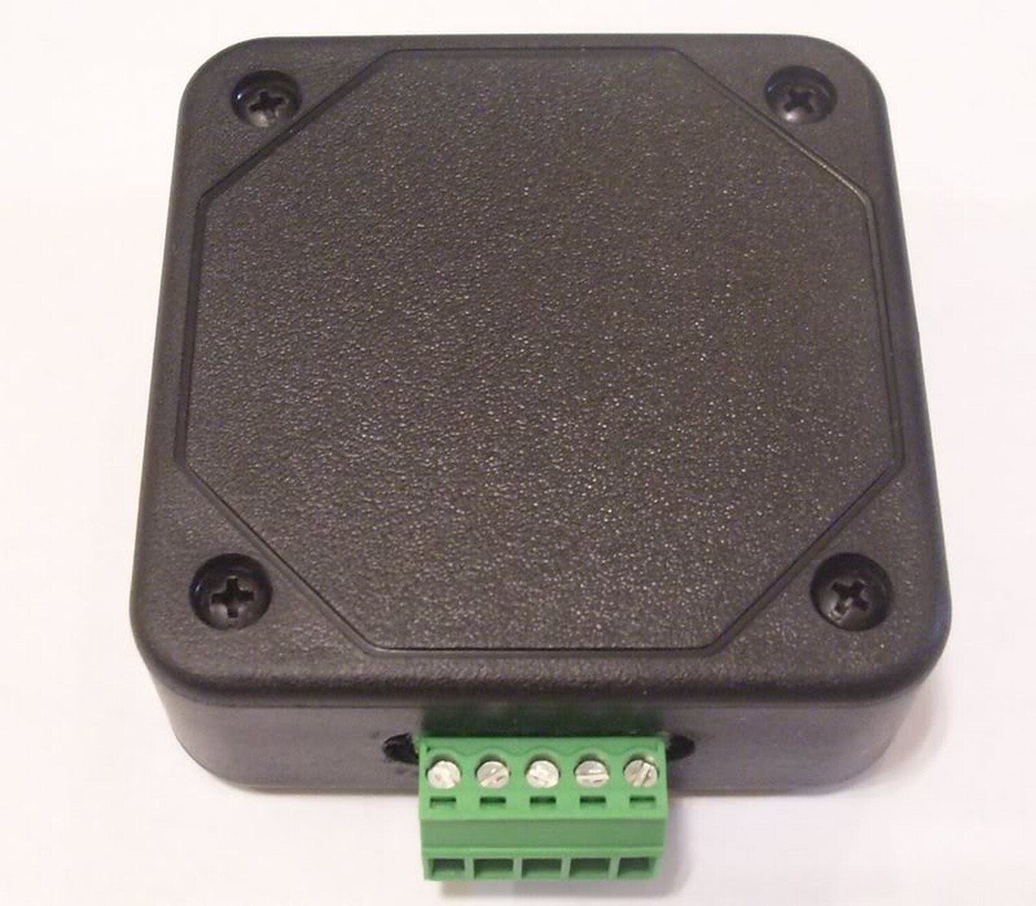
I finally finished installing my last mod. For a while I’ve been searching for a shift light indicator, but nothing as big as a Monster Tach or anything that would make the car look ricey. My idea of a shift light was something that would be small and inconspicuous.
I came across a shift light module from Raptor Performance that allows you to connect a single L.E.D or more. The module is small and can be hidden under the dash and the L.E.D or L.E.D’s can be mounted anywhere in the car. With this module you can have a shift light that is not noticeable and does not take up any space or block your view like a monster tach.
Here are the instructions on how to install the shift light. The total install time was 1 hour and quite simple.
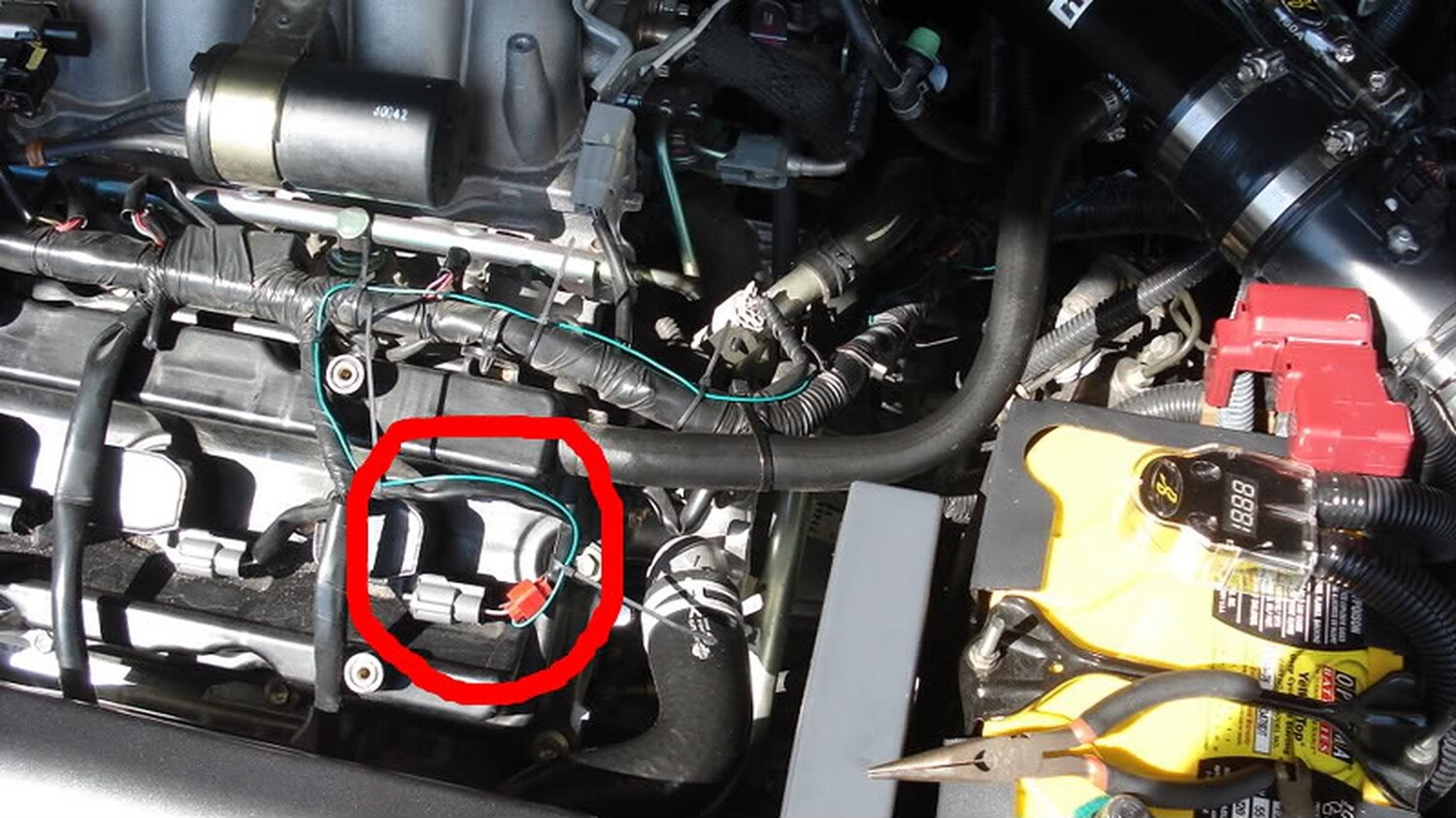
The green wire connects to the tach signal. In our cars this can be found at any ignition coil. Each coil has three wires running to them. Each coil has a red and black wire and the third wire is of a solid color with a stripe. Below is the color configuration for each coil
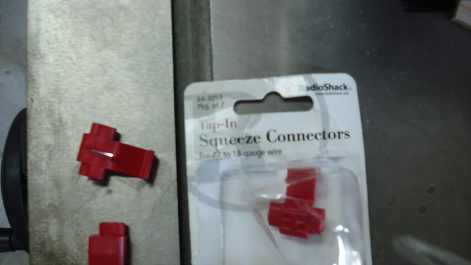
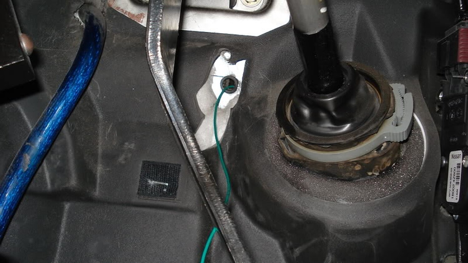
I tapped the Grey/Red wire with a 22 AWG wire tap and ran a 22 AWG wire into the cabin.
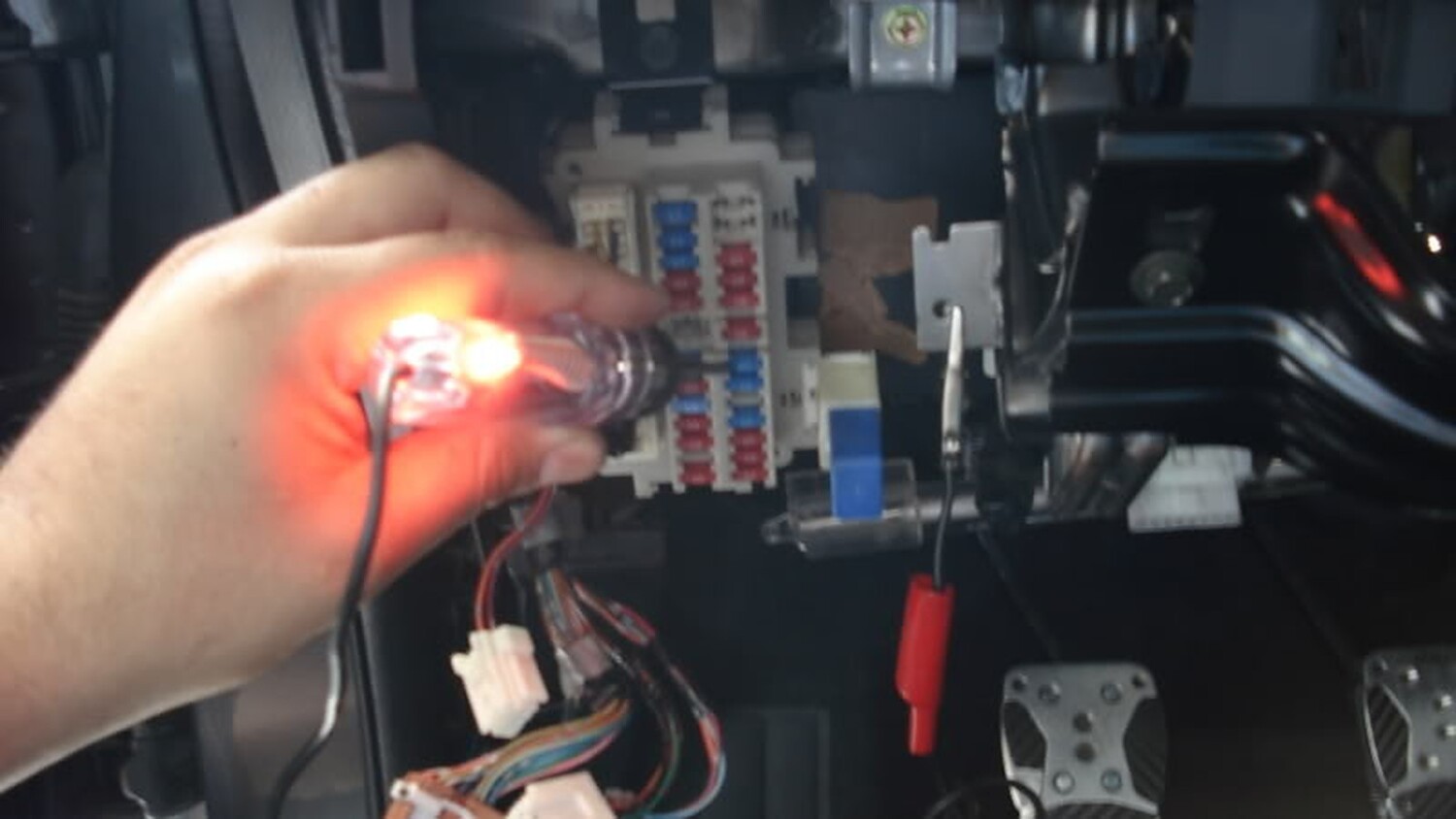
Once I finish running the other end of the wire through the firewall, the next step was to find a 12 volt source and ground. For my 12 volt source I choose the fuse for the rear power sockets
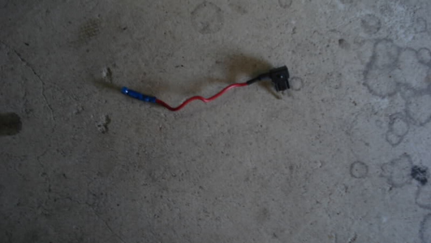
In order to use that same fuse I added a fuse tap
The tap has two slots to add fuses. One slot is used for the original fuse to work with the rear power sockets and the other is used for my new 12 volt source (tack module). Next step was to find a good grounding point
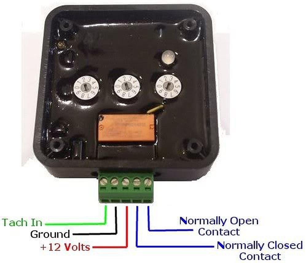
Now with the ground, 12 volt source, and tach signal connected we can now tap these wires into the harness that comes with the module. The harness has a green, red, and black wire. Green is for the tach signal and of course red for 12 volt and black for ground. The L.E.D ground will connect to the Normal Open Contact (see below ).
Now with the ground, 12 volt source, and tach signal connected we decided to install a switch so that I can turn on and off the module. I mounted the switch on the bottom of the panel below next to where the courtesy bulb connects. The 12 volt source from the fuse box connects to the switch and from the switch to the module.
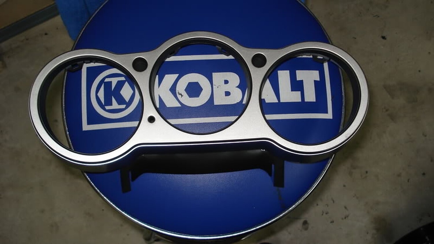
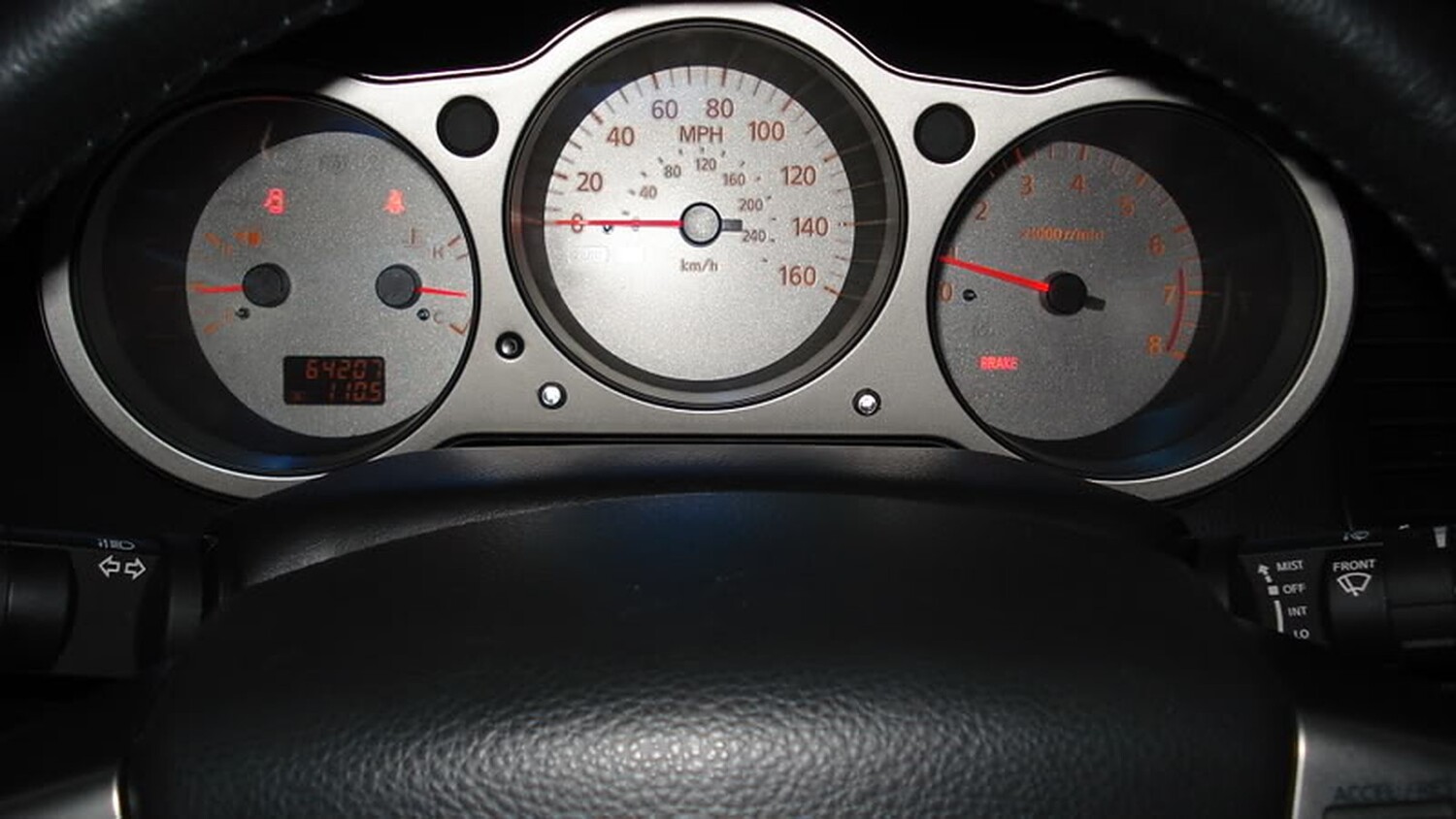
The next step is to find a spot where you want to mount your L.E.D’s. The spot I chose was on the bezel that surrounds the odometer and tach. To connect the L.E.D’s you can connect the + wire to the 12 volt tap we are using for the module and the ground you will need to connect on the Normal Open Contact.
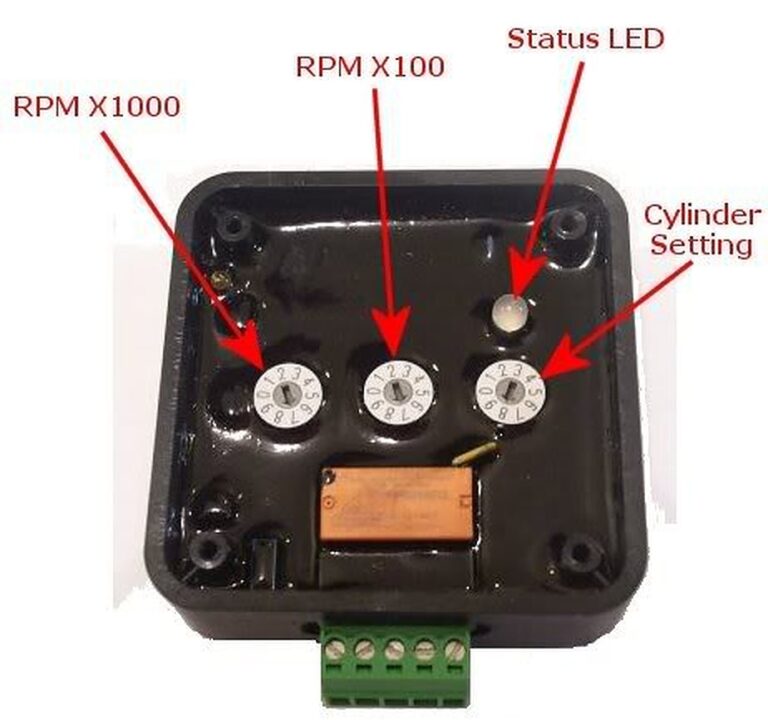
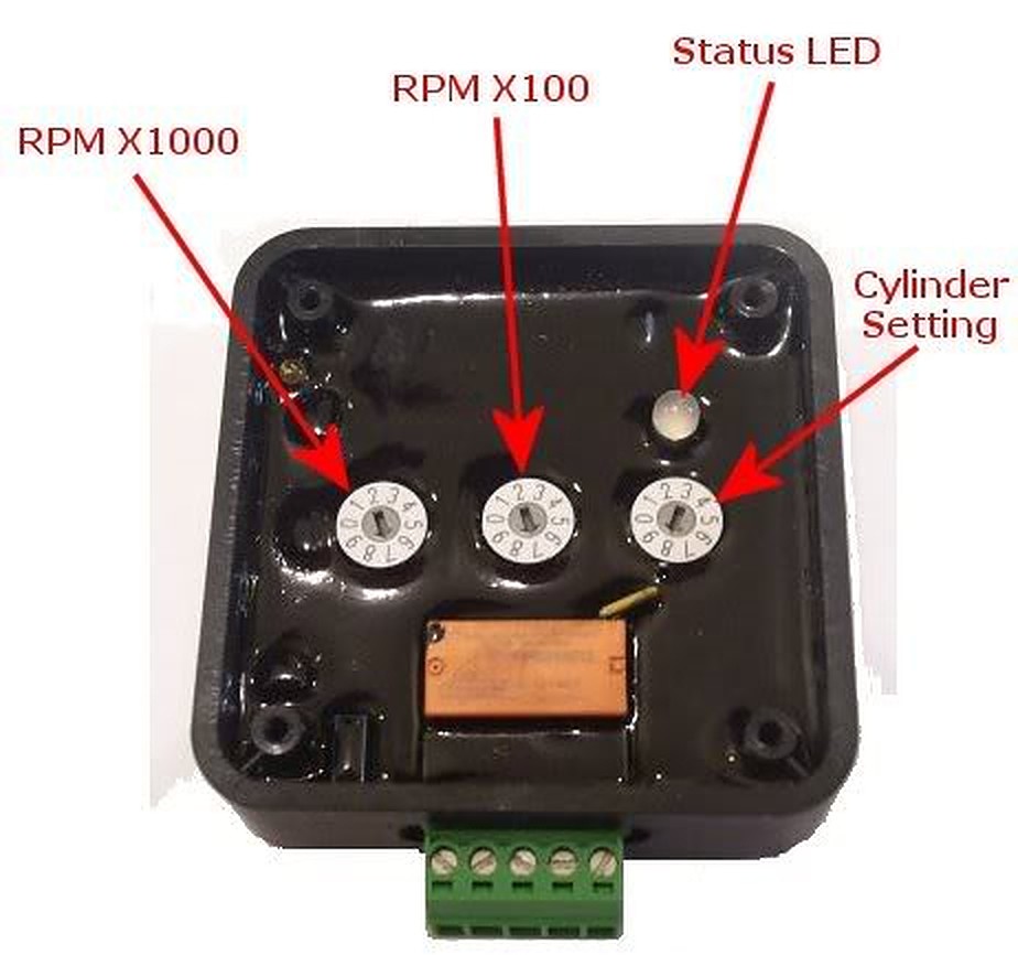
Now that we have all of this installed we can now adjust the dial on the module to your desire settings. In my case I wanted the module to send the signal to the L.E.D’s when the RPM would hit 6,100k. At 6,100K the L.E.D should light up and give me enough time to react and shift before redline.
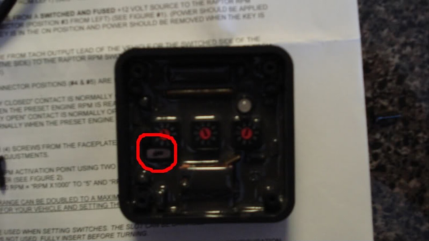
To do this I set the RPM X 1000 at 6 and the RPM X100 at 1. This gives me a dial of 6,100 RPM. If you want to do 6,500 you would set RPM X 1000 at 6 and RPM X100 at 5. Since we are only using one coil lead in our install you will only leave the cylinder setting at 1 on the dial. You will notice that there is a small toggle switch on the module. This switch was installed on the module in order to read a low volt signal from the coil.
Once you set your signal point on the module hook the harness to the module and turn on your ignition.
If the rpm switch isn’t picking up a signal after you program it (noted by rapid green LED flash), slide the small slide switch to the alternate position. Also, make sure your power switch is also on the “ON” position. If the install was done correctly you will see the following
A: The status LED will turn yellow and will flash the number of times which is representative of the RPM X 1000 setting
B: There will be a pause for about two seconds (no status LED flash)
C: The status LED will turn red and will flash the number of time which is representative of the RPM X 100 setting
D: There will be another pause of two seconds (no status LED flash)
E: The status LED will turn orange and will flash the number of time which is representative of the “cylinder setting” (in our case 1), and finally the module will do an LED test (alternating red & yellow) and be ready for use.
Once this is done close you module with its cover and install anywhere under the dash. I installed mine with double sided tape. Clean up the mess and enjoy.
Here is a video of how it works on my car. BTW, I want to thank my other half for helping me record the vid.
Alright…there seems to have been many many questions about the install of the newer OBX Headers/Y-pipe. So I have decided to do a small writeup on the installation of these headers/y-pipe. So below I have made a faq with some of my answers that should be right but if I am wrong on anything feel free to let me know…and like everything else, this is a guide to help you on your install and any questions you have, so if you screw something up it is not my fault
FAQ
1. Are these worth saving the extra money over the Cattman’s?
(Answer) If you are a do-it-yourself kind of person then yes definitely, the Cattman’s are an awesome product and have no fitment issues whatsoever (I have owned a set of Gen III’s) and the peace of mind is nice, but if you aren’t afraid to do some small modifying and saving around $500 sounds good then yes the OBX headers are for you.
2. Do these make decent power compared to the Cattman’s?
(Answer) The OBX Headers make just as much power as the Cattman’s. Depending on who you ask some will tell you they make more but I think that since the dyno’s differ I would say all around they make around the same power.
3. I have heard you have to extend the O2 sensors, is this all 4 or just the primaries?
(Answer) Alright, when I installed my headers all I had to extend was the primaries which are the O2 sensors in the collectors of the headers…now if you choose to plug up the secondary O2’s then you might have to extend them, I don’t know because I did not hook mine up.
4. Do you have to relocate the rear bung for the primary O2 sensor?
(Answer) Don’t know if you absolutely have to but I would 100%…it makes the install a lot easier and you won’t be so worried about it hitting the steering rack and whatnot. All you need to do is move the bung 90* to the right on the collector and your good to go, you could have a shop do this for you or for the DIY’r you could do it in your garage (like me…lol)
5. Will I throw a SES with these headers?
(Answer) Yes most likely, since you do not have any precats for the secondaries to monitor you will throw a code which is why it is useless to plug up the secondaries to begin with since they will still throw a code because there are no precats. The SES light thrown will not effect your performance at all because the primaries are the only O2’s that affect your A/F ratio. Now all you need is a dual output O2 simulator which you can get from here: http://www.02sim.com/ Some have reported not throwing a SES and most get one. When I installed my Cattman’s I threw one upon first startup, with the OBX’s I have been driving around for 1 1/2 months now without a simulator and have yet to throw a code, but that’s just mine.
6. Should I use the gaskets included with the headers or the OEM ones?
(Answer) Definitely use OEM multi-layer gaskets because the ones included like every other header kit are crap. Now if for whatever reason you have to use them then they are ok but plan on changing them down the road because they won’t last as long as your OEM ones.
7. Is there that much modifications to make these work?
(Answer) That depends on who your talking to. I didn’t think it was that bad. The only modifications I had to do was to move the rear bung 90* to the right, plug the 2 secondary holes in the y-pipe, trim down the crossmember like 1/2 inch for the flex section, and then grind down the rear motor mount bracket peice for the primary tube on the rear header. That’s it. Not bad at all. Some people claimed to have installed them without any modifications but I would plan on doing the above on your install.
8. Do you have to have a lift to install these headers?
(Answer) NO!!!! You can install these with your car on jackstands…I installed both my Cattman and OBX’s with the car in my garage on jackstands. Even with the one peice rear header/y-pipe deal it’s not that bad. The y-pipe header peice doesn’t weigh that much and once you get everything trimmed and out of the way it isn’t that hard to put up on the head.
That’s all the questions I could think of for now, I am working on the Install Writeup as you are reading this so I will post in a little bit, but I hope this helps out a lot with some of the questions and concerns people are having with these headers.
Installation:
Now bare with me hear as I installed these quite a while ago, so if I left something out please feel free to let me know because this is going off of memory, I didn’t take a gazillion pics either so it will mostly be an overview because I’m assuming you guys can figure out the small details . So use this as a basis to go off of when you are installing your headers, it’s not an instruction manual but I’m sure it’s a good outline to follow.
Alright first things first. Here is a pic of the bung relocation courtesy of C-Young:
1. Remove your filter, midpipe etc. off of your intake.
2. Proceed to remove your intake manifold (12mm) upper only though.
3. Remove your Radiator fans, only 2 bolts on top (10mm) and 2 on bottom (10mm) unplug them as well.
4. Jack up the car and put on jackstands.
5. Take off the passenger side splash guards.
6.Take off the front heat shield off the header.
7. Undo the 2 front O2 sensors and the rear secondary. 22mm wrench or an adjustable wrench.
8. Unbolt y-pipe completely from the precats and the cat.
9. Unbolt exhaust manifold from head.
10. Drop the front manifold throught the bottom.
NOW THE EASY PARTS OVER….LOL
11. Undo the rear O2 sensor off the rear manifold
12. Now it would be easiest to unbolt the precat from the rear manifold but mine decided to be tricky and stripped out so I couldn’t undo it so it was a little hard to get to the nuts for the header.
13. Unbolt the rear manifold using a combination of underneath the car and from on top to get to the different nuts.
14. Bolt the front header to the head.
15. Go ahead and test fit the y-pipe/header and see where you’ll need to cut (even though you already should know by now…lol)
16. Grind down the crossmember so that it’s not touching the flex section.
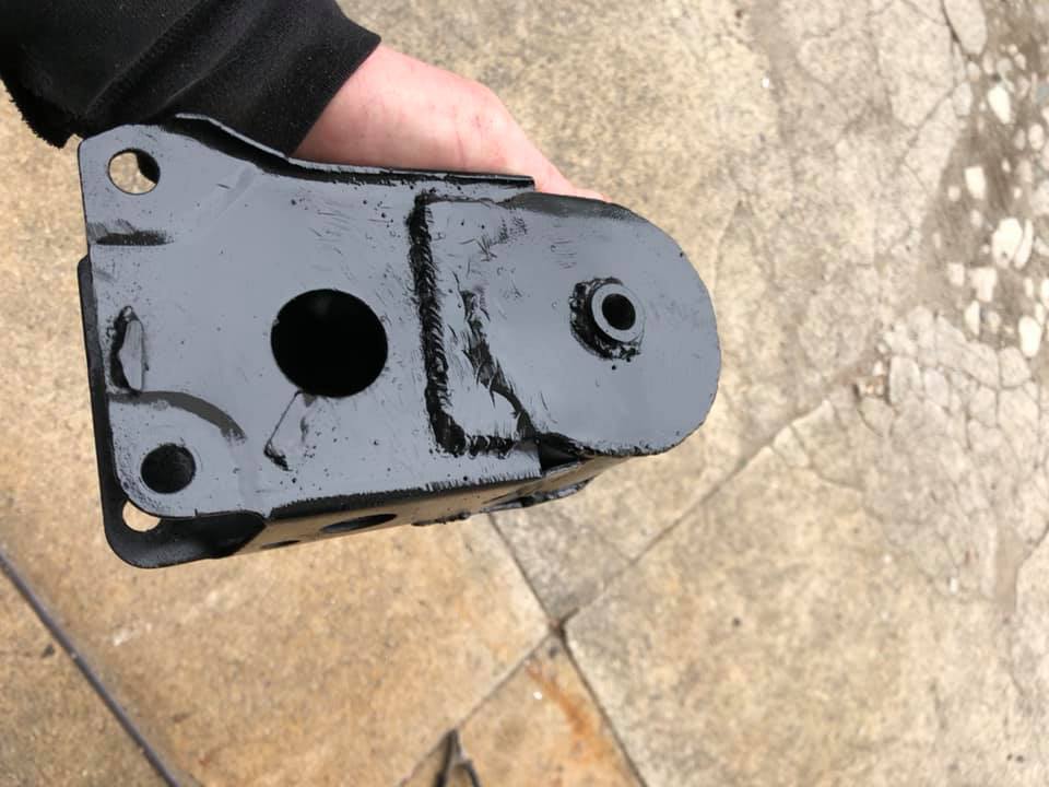
17. Now grind down the rear motor mount peice on top that’s almost just like a cover for the top of the mount, this can be kind of tricky, I’ve found it to almost be easier to undo the mount from the engine and cradle and take out of the car and since all you are grinding is a plate you can just cut it all the way off…photo courtesy of datdude20.
18. Your header/y-pipe should now slide up into place.
19. Bolt on header to head
20. Bolt y-pipe to cat and to front header.
21. Plug in your O2 sensors. You may need to use some zipties on the front because my wire was being hit by the fan so I ziptied it so it wouldn’t hit.
22. Double check and make sure everthing is bolted up tight so you won’t have any leaks.




















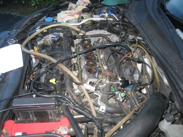
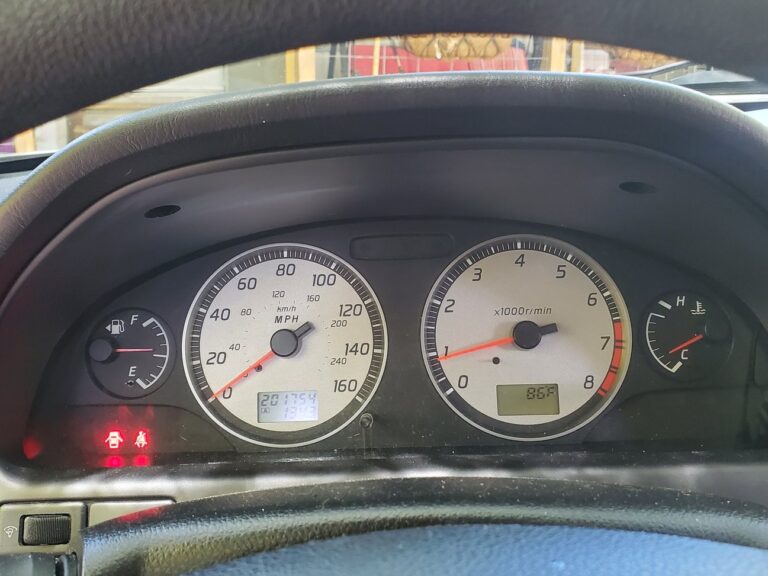


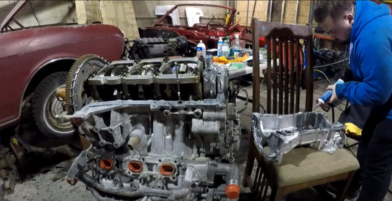
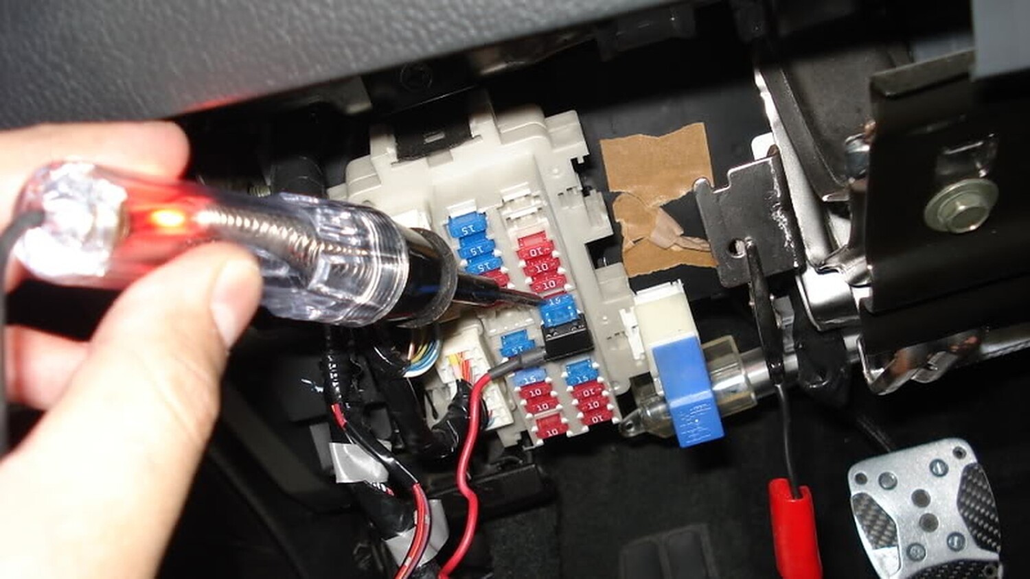
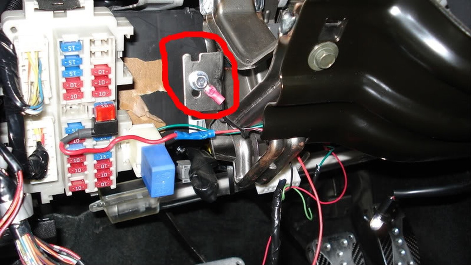
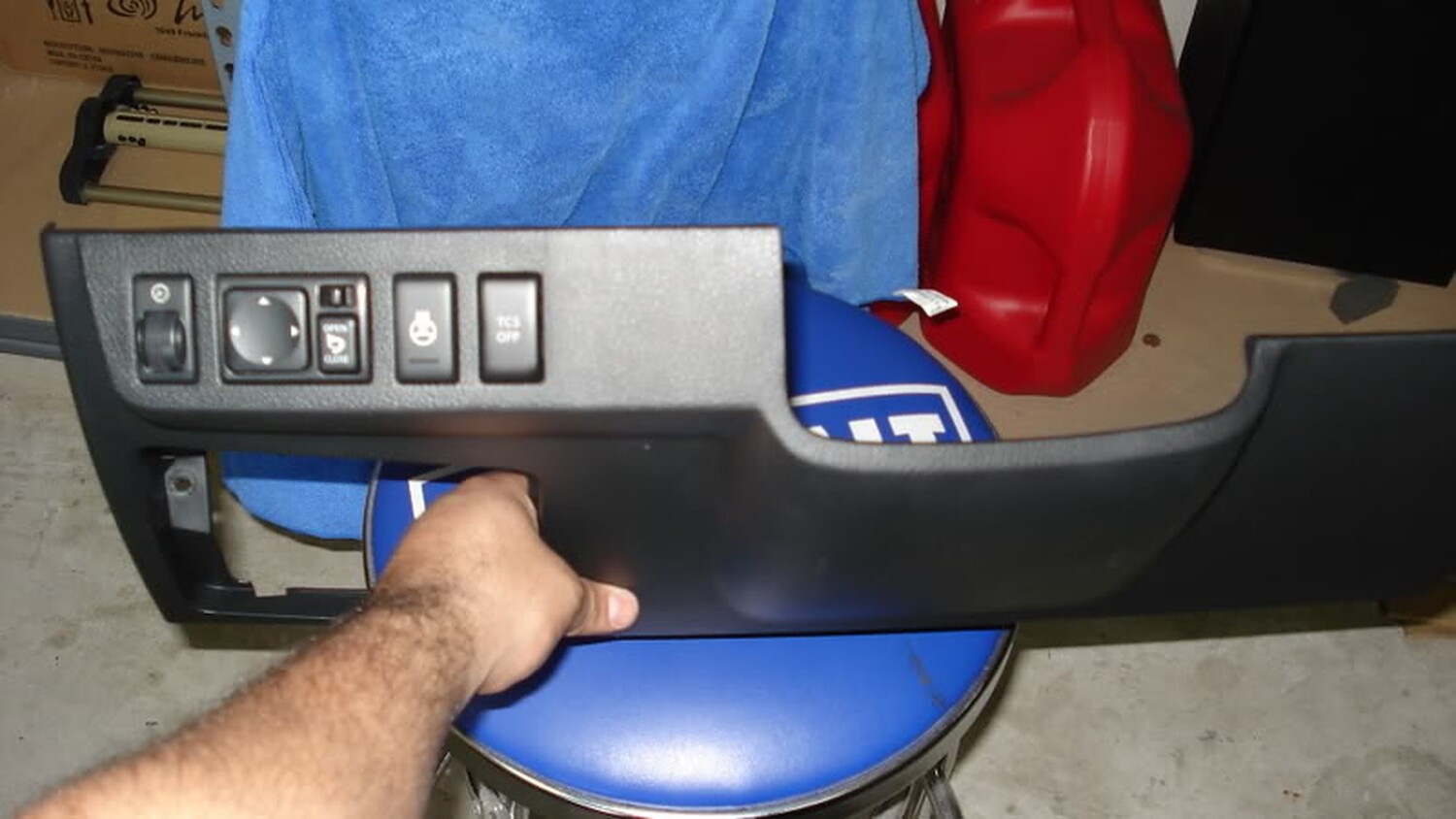
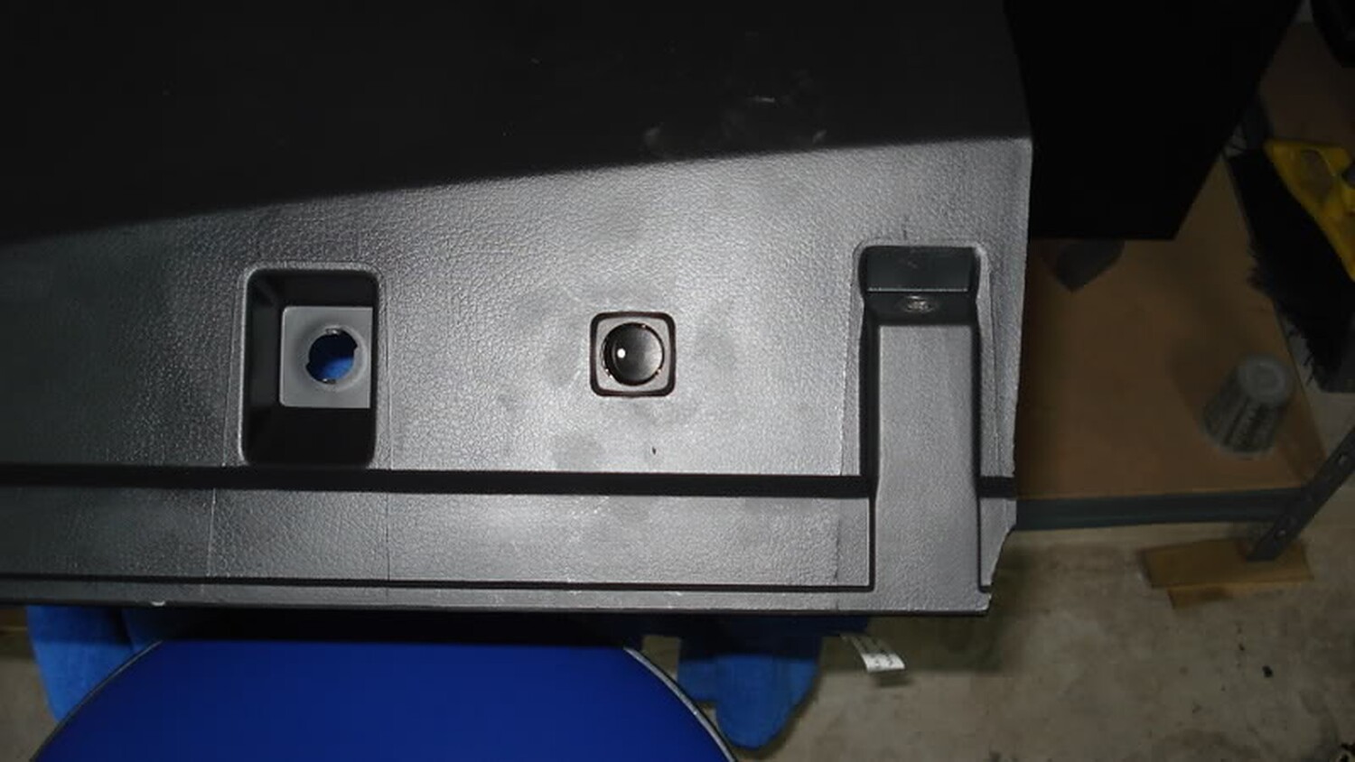

 . So use this as a basis to go off of when you are installing your headers, it’s not an instruction manual but I’m sure it’s a good outline to follow.


