10 mm Socket, 12 mm Socket, 14mm Socket, 15/16, Swivel extension
Clutch Master Cylinder
Pliers
PB/slick 50 etc…
10mm Wrench for Hydraulic Line Screw
Instructions
1. Disconnect clutch fill cup two 10mm screws (no need take of bracket just cup).
2. Locate clutch master cylinder on the inside of the brake master cylinder.
DONT PANIC when you see how far it is in there.
3. Look under your dash and locate the clutch pedal and follow it all the way to the top until you see a small goldish retaining clip and gold pin holding the clutch master cylinder shaft to the pedal. REMOVE THE CLIP AND PIN
4. Follow the master cyl shaft to the firewall you will see 2 – 12 mm screws. Using your wrench/extension/12mm/swivel socket remove both screws.
5. Get a 14mm socket and remove the windshield wipers.
6. Just under your windshield wipers is a black plastic cowl pull it up in the center and all the plastic fasteners will pop up.
7. Remove the windshield wiper motor and assembly 3 – 10mm screws disconnect pigtail.
8. Just under that is a fake me out strut tower brace just under your windshield wiper cowl. locate the 6-7 10mm screws and remove them. FakeSTB!
9. You should now clearly see the clutch master cylinder using a 10mm wrench remove the hydraulic line connected to the top of it.
10. Remove the master cylinder and clutch fill together makes it easier to remove the clip holding the fill cup hose to the master cylinder. should look like this removed
11. Install the new one connecting the retaining clip and pin the the clutch pedal first then tighten up the screws
You are basically done now. I suggest bleeding the clutch before you put everything back just to make sure the master cylinder works correctly.
Clutch Bleeding 101
1. Fill the clutch cup to the top. (you do not need to put the top back on the pressure that the dealer claims need to be there is BS! The way it works is once you depress the clutch the valve closes so no air will ever get in it. I posted this 2 years ago because I listened to the STEALERSHIP and I was totally wrong also so I apologize for the misinformation back them.
2. Get a 15/16 socket (tiny) go to your clutch slave cylinder and unscrew the bleeder valve.
3. Go back to the inside of the car and pump the clutch with your hand 3 times. pour brake fluid in the clutch cup then go back and pump it another 3 times. I suggest doing it a total of three times just to make sure all air is out of the line.
4. On the last or third try when you push the clutch to the floor LEAVE IT TO THE FLOOR and go and close the bleeder valve. go back and pump the clutch after 3 pumps it should be extremely tight. That’s it your done.
Now just put everything back together.
HELPFUL HINT: If ever you come into a situation when your master cylinder fails while driving or at an intersection or tractor trailer coming at you and it won’t let you shift. Turn the car off and you can put the car into first without the clutch turn it back on and take the hell off 🙂
The mixture ratio feedback control system monitors the mixture ratio signal transmitted from air fuel ratio (A/F) sensor 1. This feedback signal is then sent to the Engine Control Module (ECM). The ECM controls the basic mixture ratio as close to the theoretical mixture ratio as possible. However, the basic mixture ratio is not necessarily controlled as originally designed. Both manufacturing differences (i.e., mass air flow sensor hot wire) and characteristic changes during operation (i.e., fuel injector clogging) directly affect mixture ratio.
Accordingly, the difference between the basic and theoretical mixture ratios is monitored in this system. This is then computed in terms of “injection pulse duration” to automatically compensate for the difference between the two ratios.
“Fuel trim” refers to the feedback compensation value compared against the basic injection duration. Fuel trim includes short term fuel trim and long term fuel trim.
“Short term fuel trim” is the short-term fuel compensation used to maintain the mixture ratio at its theoretical value. The signal from air fuel ratio (A/F) sensor 1 indicates whether the mixture ratio is RICH or LEAN compared to the theoretical value. The signal then triggers a reduction in fuel volume if the mixture ratio is rich, and an increase in fuel volume if it is lean.
“Long term fuel trim” is overall fuel compensation carried out long-term to compensate for continual deviation of the short term fuel trim from the central value. Such deviation will occur due to individual engine differences, wear over time and changes in the usage environment.
Instructions
Start engine and warm it up to normal operating temperature.
Turn ignition switch OFF.
Disconnect mass air flow sensor harness connector, and restart and run engine for at least 3 seconds at idle speed.
Stop engine and reconnect mass air flow sensor harness connector.
Make sure Detected Trouble Code (DTC) P0102 is displayed.
Erase the DTC memory. (This could be done by disconnecting the car battery for 30-45 min or with a scanner)
Today I finished refurbishing the metal water pipes that run along the left side (e.g. nearest the radiator) of the engine.
After sanding and refinishing the pipes, I used some ceramic VHT exhaust header primer and paint that I had leftover from the Y-pipe. I’ve been slowly baking the pipes this afternoon to cure the ceramic paint before I do the installation. I’ve got to make sure the ceramic paint is fully cured and hardened before installing the o-rings and heater hoses. I did have to spend quite a bit of time sanding and polishing the hose connection areas to smooth off some rust that had formed between the hose rubber and the pipe. We’ll see how well the refinished hose and o-ring connection areas will hold up over time. The pipes are now in better condition than when I started.
Here are a couple of pictures that we may want to reference when someone has a water leak or needs to replace the o-rings or gasket. I like the Felpro gasket with the extra “red seal” area for the aluminum hose manifold mating surface. In the end, I reused some OEM o-rings that I already had on hand. I recommend using OEM o-rings as they will be the correct size.
I used 0000 steel wool to polish the aluminum pipe manifold o-ring and gasket mating surface areas. I might have been better off buying some new OEM pipes that come with a factory powder coat. But we can see how long the refurbished pipes last in the meantime.
Pardon my phone camera, as the pipes are actually a silver metallic color that matches the aluminum pipe manifold part.
Here are a couple of pictures with the refinished pipes on the car. Valve cover polishing was still a work in progress when I took a break to snap the following picture.
I changed the 10mm short bolts pipe mounting bolts to use hex cap heads with lock washers in the picture.
Refinishing the pipes baking the ceramic paint has been a small project in itself. The only reason I attempted it is the easy-to-reach location if something backfires on me. A
s a side note, the OEM heater supply pipe on a VH45DE comes nickel-plated from Nissan. So all I had to do when I got a new one was to polish it up a bit and then clear coat it for the long haul. On a VH45DE the pipe lives at the bottom of “death valley” buried under a Gordian Knot of hose and wiring harnesses. You don’t want to miss anything that could come back as a leak or a problem after you put one of those critters back together. You can see it in the picture below the supply pipe running underneath the short pieces of head coolant hose.
Here are a couple of pictures with the refinished pipes on the car. I sure hope the o-rings hold up. The pipes felt solid and I could tell the o-rings were sealing the connections.
Valve cover polishing was still a work in progress when I took a break last night to snap the following picture. More to come with engine details about the coolant crossover pipe.
The original 10mm mounting bolts were changed to use stainless hex cap heads with lock washers in this picture. If possible, I like to use this type of bolt for coolant and fuel connection bolts.
Fortunately, the 99 model (with a 95 model engine) where I refinished the pipes, had under 80,000 miles. I didn’t notice any rust on the inside of the pipes. The pipes came with an engine from a local car that had been in a bad rear end collision. I bought the motor and had it installed in the 99 model.
This year, I took the pipes from the 99 model’s original engine with under 170,000 miles and refinished them for the 98 model with over 235,000 miles.
There is a 2nd thread on this topic, where I refinished the pipes from the 98 model. Those pipes are some of the worst that I’ve seen to date. In the time frame for the 98 model project, I discovered soaking metal parts in muriatic acid removes rust in a hurry.
I think the quality of water that is mixed with anti-freeze to make coolant has a lot to do with the formation of rust or barnacles in a cooling system.
The 98 model lived in a part of the state when iron deposits in the water so high that people use water softeners to condition the water for indoor use. The iron content in that area’s water will stain plumbing fixtures unless the water is conditioned before use. I could see that in the cooling system when I had it open.
One of my cars, lived for many year in a part of TX that must have had a lot of sulfur or calcium in the water. I found crusty mineral deposits inside its cooling system.
Even though the area where I live has good water that does not require conditioning before use, I like to use a 50/50 mix of distilled water and Xerex G05. After seven years of use on all of my Nissan products, it seems to work.
So here’s a picture of the acid bath where I cleaned up some pipes and put them away in my workshop for another project. Naturally, some light surface rust has appeared on the freshly cleaned pipes because I didn’t prime and refinish. I have an EGR pipe that I will treat sometime later in the year. I have another VQ30 from an I30 that I will be semi-overhauling to have on the shelf in the event I need a replacement engine.
Here’s a picture of the pipes that were refinished in this thread almost 3 years later. I am satisfied with how they are holding up. No surface rust, no complaints, and low maintenance.
I see a coolant flush product advertised for removing rust. This seems to be more popular with iron block engines.
If you find one that you think is safe to use on an aluminum engine, you might try it. One thing to note is acid and aluminum do not get along very well.
An aluminum part that is submerged in a muriatic acid bath that is strong enough to remove rust from metal parts, will fizz like an effervescent tablet. You can watch your part turn dark and start to dissolve right before your eyes. So I would use caution with a coolant flush that was designed for iron block engines that contains a lot of acid.
On one aluminum engine car, I used vinegar like the guy in this video. Though I followed it up two or three distilled water flushes to neutralize the vinegar before refilling with Zerex.
Many years ago I would see some coolant flush products shorten the life of water pumps. So I’ve always been hesitant to use a lot of chemicals to flush a cooling system.
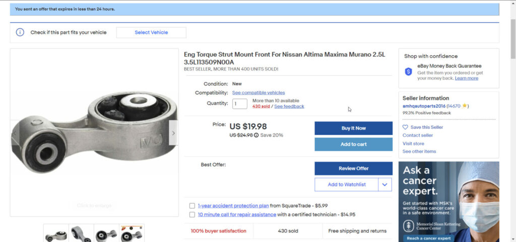
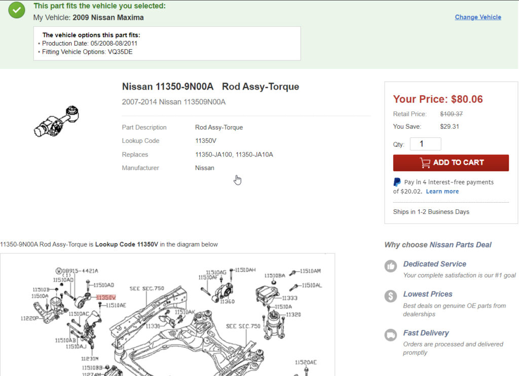
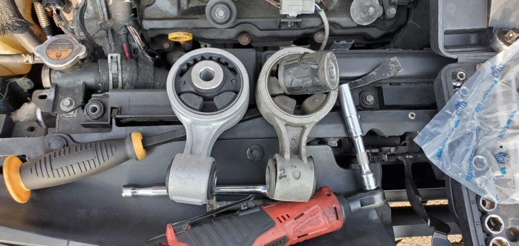
I decided to finally replace the upper torque mount on my 2009 7thgen Nissan Maxima with 220K+ miles. The mount was fully busted. I looked on eBay and found a replacement for $20 bucks vs $80 for OEM. Upon inspecting the two mounts, they were pretty much the same. Given the age and miles of the car, the aftermarket mount was the better route for me. I believe this is the first time this mount has even been replaced. It took me and my 12-year old about 20 minutes to swap this out.
Fitment:
2007 – 2012 Nissan Altima 3.5L-V6
2009 – 2014 Nissan Maxima 3.5L-V6
2009 – 2016 Nissan Murano 3.5L V6
2013 – 2016 Nissan Pathfinder 3.5L V6
2011 – 2017 Nissan Quest 3.5L V6
Upper Torque Mount
OEM Part Number: 11350-9N00A Price: $80.06
Aftermarket Part Number: A7363 Price: $19.98 (Shipped)
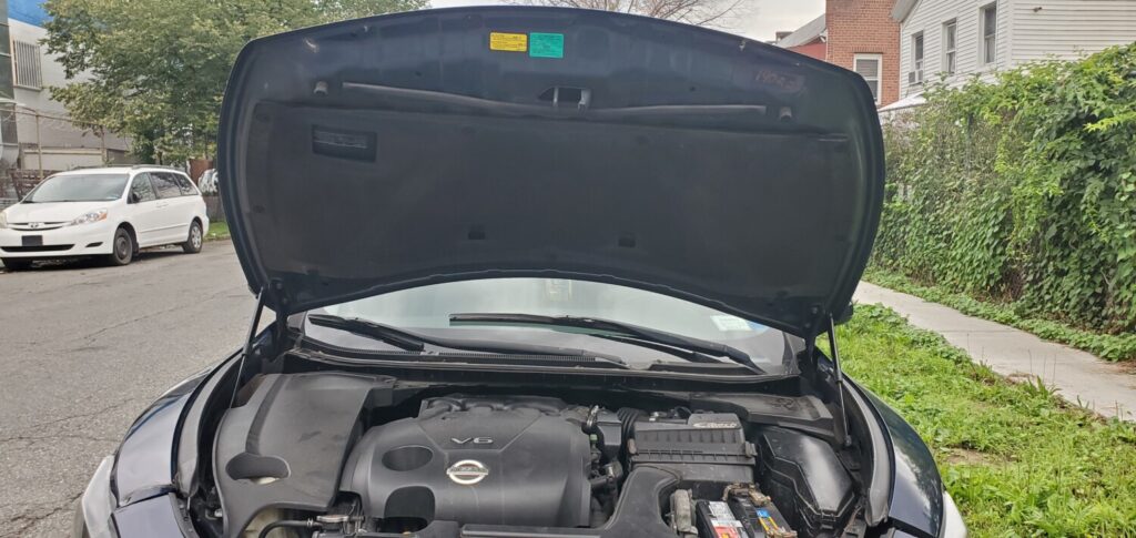
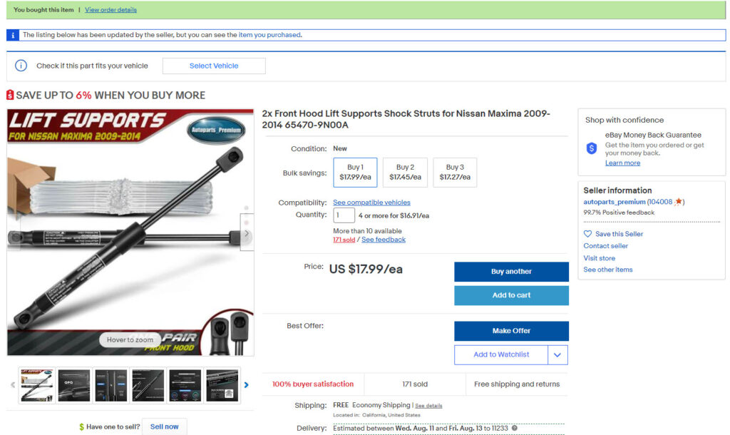
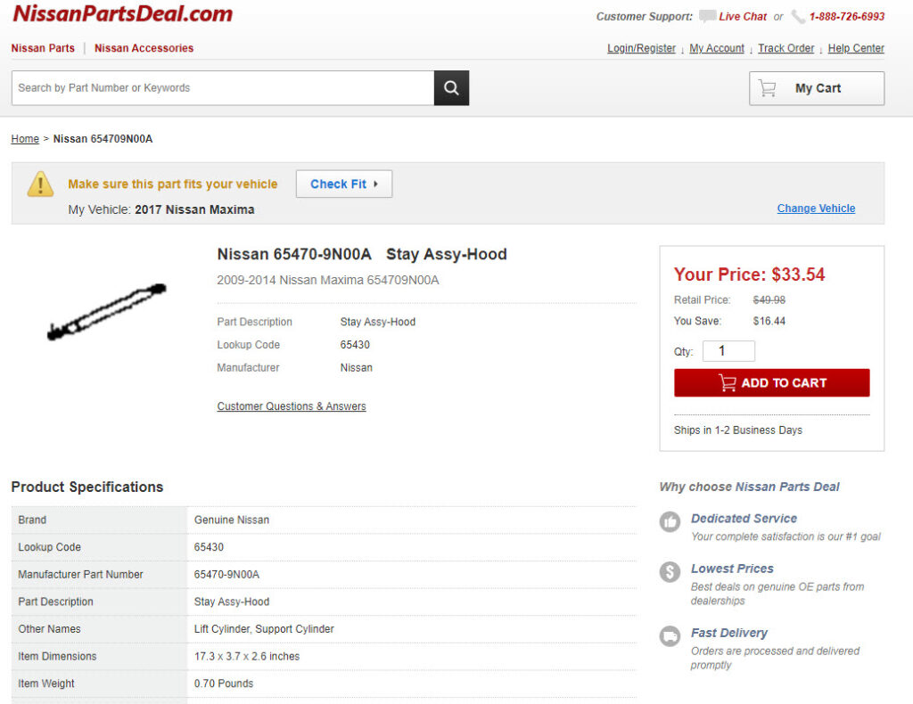
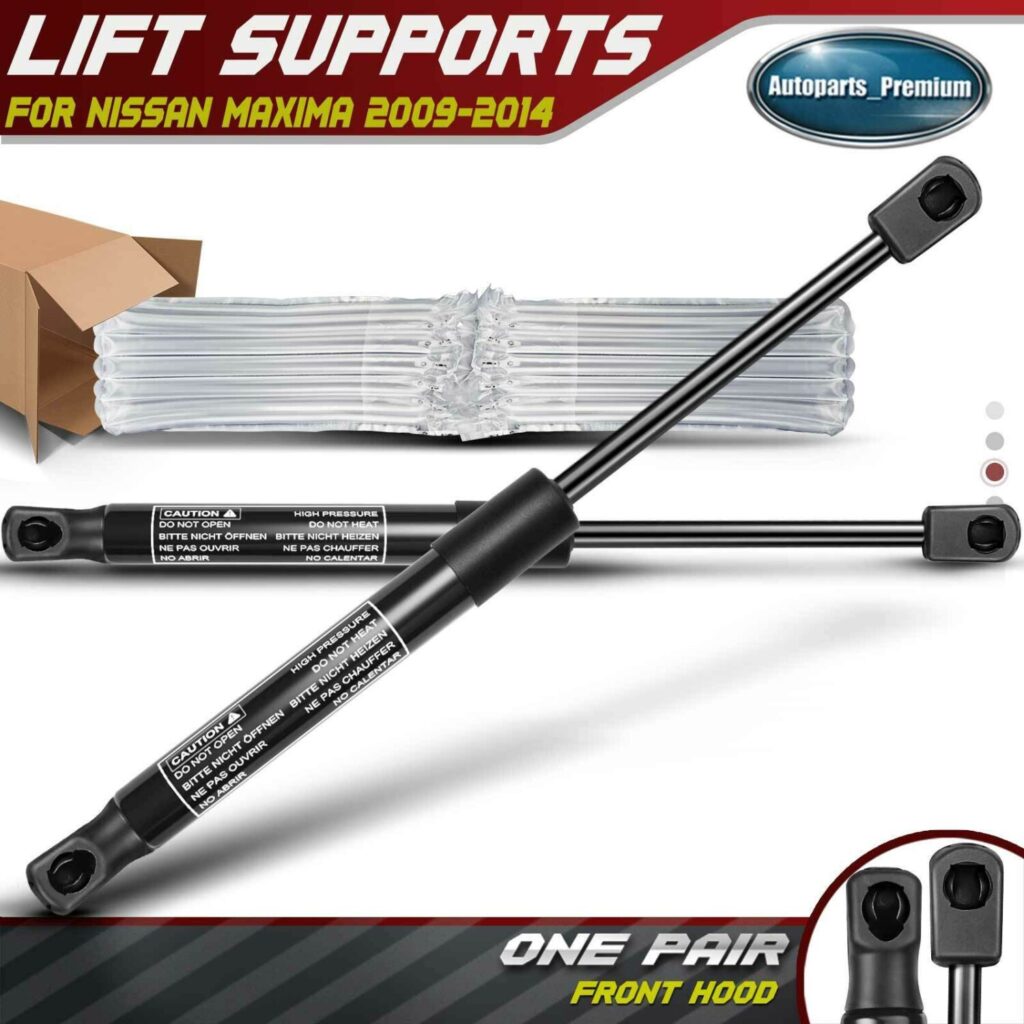
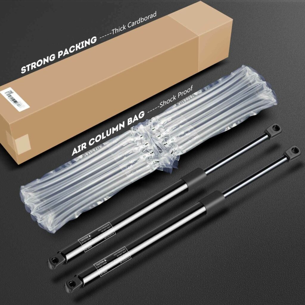
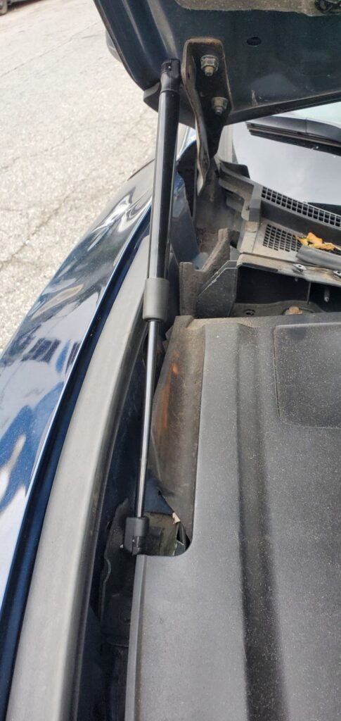
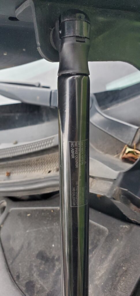
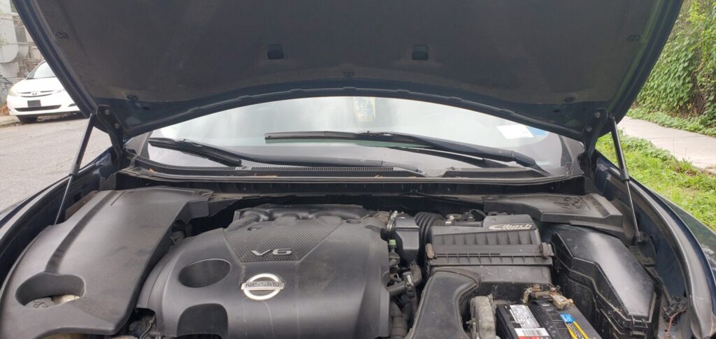
The hood on my 2009 was not staying up and I had to use a stick each time to hold it up. Car has over 220k+ miles and this part has not been changed.
I decided to buy a set of aftermarket hood struts (I’ve used them before) and they worked perfect. Plus you save a bunch of money. They aftermarket ones work just as good. But if you are an “100% OEM only person”, you can also buy them using the part number below.
OEM Part Number: 65470-9N00A, 65471-9N00A Price: $33.54 each
Aftermarket Part Number: PM3283 Price: $17.99 Shipped (Includes Both)
I just installed these aluminum valve covers on my 5thgen Maxima. AND YES, THEY ARE ALUMINUM! The brand is MITZONE. They are well-made and come with gaskets. I have no leaks or problems so far. They are also very sturdy/solid vs. the crap plastic stuff. Highly recommend.
eBay Description: ALUMINUM Valve Cover Kit for 02-09 NISSAN Altima Maxima Murano Quest I35 3.5L Price: $87.99-$95.00 (Shipped)
Order Links Below:
Issues: My power sunroof switch stopped working this weekend on my ’03 Maxima GLE. I pull it backwards for the sunroof to slide back and nothing happens?
Solution:
This happens to me almost every time I disconnect my battery terminal. I found that this will usually fix it: Use the sunroof tilt switch to open it all the way (you will have to push it a bunch of times), and then do the same thing to close it all the way. Once you open it and close it all the way using the switch, then try using the slider switch thing, and it should open. If it doesn’t, turn your car off and back on and try again. This works almost every time for me.
You shouldn’t have to open it all the way. Just close it and hold the tilt switch (close) until you hear a click…that will reset the switches.
How to Fix/Reset Sunroof motor:
Close your sunroof all the way.
Turn off your car.
Disconnect your battery.
Turn on your lights, and step on your brakes. Do it like 10 times. (You are basically draining the system.)
Here is a list of things that need to be done for the 60K service.
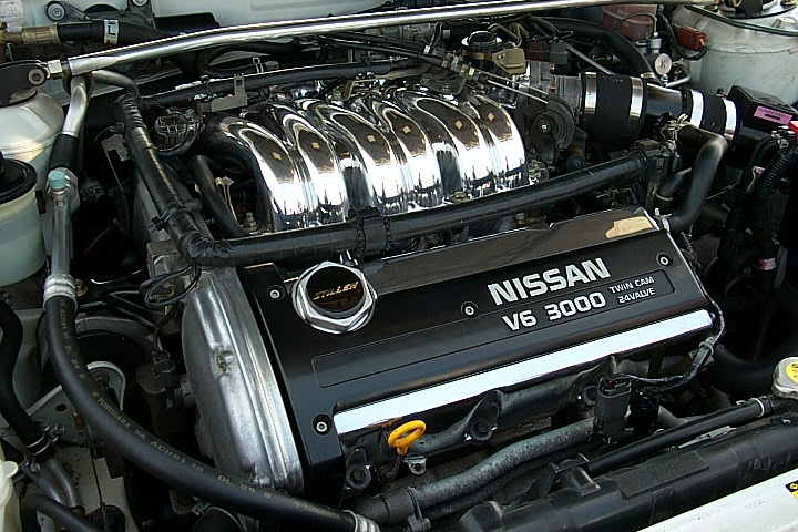
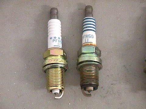
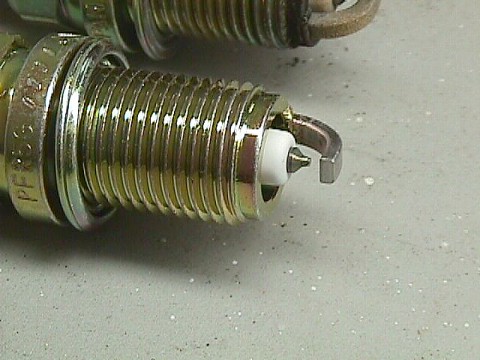
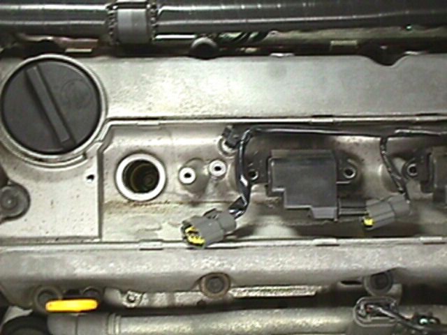
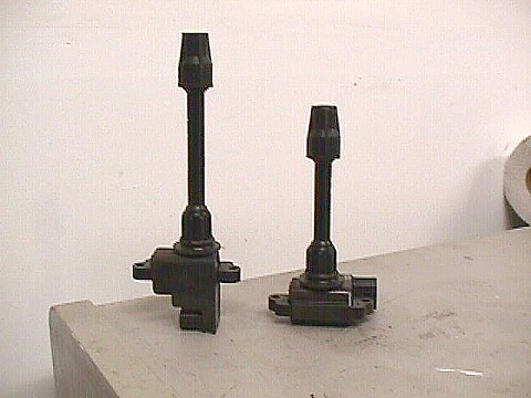
Spark Plugs: 6 NGK Platinum spark plugs are required for the tune-up. Platinum plugs do not need to be gapped. If you use copper plugs the gap is .044. Put anti-seize on the spark plug threads and torque to 18 ft/lbs. The spark plug socket is 16mm or 5/8. The spark chambers are very deep as you will find out. A magnet will help to remove and install the plugs. Also a couple of socket extensions are necessary. Remove the spark plug cover (Nissan V6 3000) to reveal the front three plugs. The rear three plugs are behind the exhaust manifolds. The last picture shows an approximate location.
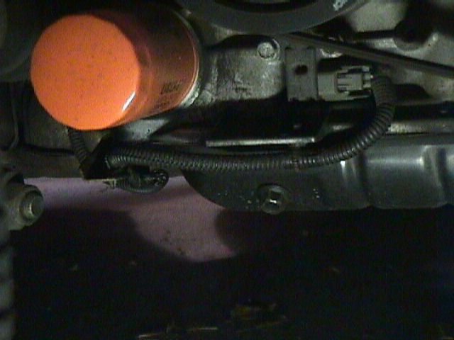
Oil Change: Make sure the car is on a flat surface. Turn the steering wheel all the way to the right. The filter and plug are behind a panel in the passenger fender well. There are about 4 Phillips head screws holding the panel in place. There is one more Phillips head screw under the front nose of the car that needs to be removed. Once the panel is removed you can see the plug and filter. Remove the drain plug (turn left) and make sure that you keep the crush ring that is on the drain plug. Nissan recommends that you replace the crush ring ever oil change. The ring should be good for about 3-4 oil changes. Remove the old oil filter and then reinstall the oil plug. Put fresh oil into the new filter and install. When the filter gives slight resistance turn it another 2/3 of a turn. Tightening the filter by hand is all that is needed. Add 4 quarts of fresh oil and then start the car. The car takes 4.5 quarts but make sure that you do not over fill. The Nissan filter # 15208-31U00.
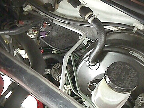
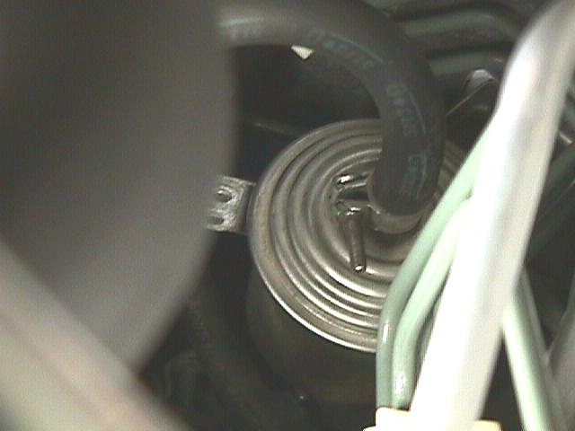
Fuel Filter: The filter is located against the fire wall near the brake fluid. There is no real easy way to remove the filter. It has a hose clamp at the top and bottom of the filter. The hose clamps are tightened with Phillips head screws. The problem is Nissan did not leave a lot of room to get a screwdriver in there in order to remove the filter. If you want to attempt to change the filter here are a few tips. Leave the car running. You will need to remove the fuel pump fuse. The fuse panel is under the steering wheel on the left. Locate the fuel pump fuse and remove it. In about 5-10 seconds the car will stall. Try to start the car at least one more time. This releases the pressure in the fuel line. Turn the car off completely. Now try and remove the top and bottom hose on the filter. When reinstalling the filter make sure that you don’t install upside down. When new filter is installed put the fuse back in and start the car.
Transmission Fluid: The drain is under the transmission near the driver’s side of the car. The fill is in the front of the engine and looks like a large square opening. In order to open that fill plug you need a 1/2″ ratchet with out the socket. The transmission takes 4.5 quarts of MT-90. I have provided a picture from the shop manual to show the location of the drain bolt and fill plug. Easy way to fill the transmission is to get some plastic tubing and tape a funnel to one end.
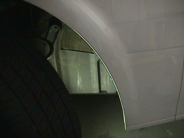
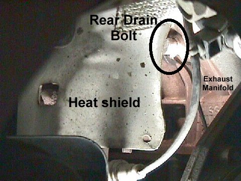
Radiator Coolant: The radiator takes 9.5 quarts of fluid. The mixture is 50% coolant and 50% distilled water. There are 3 drains that you need to find. One is the radiator drain which is directly under the radiator. The second is in front of the engine dead center near the exhaust manifold. Third is in back of the engine. Here is a picture of the third drain bolt. If you take off the passenger front tire, look on the left side of the front shocks and turn your head a little to the right. That is were the picture is looking. The bolt is in the top right of the picture left of the black wire. I had the dealer to it for under $50.
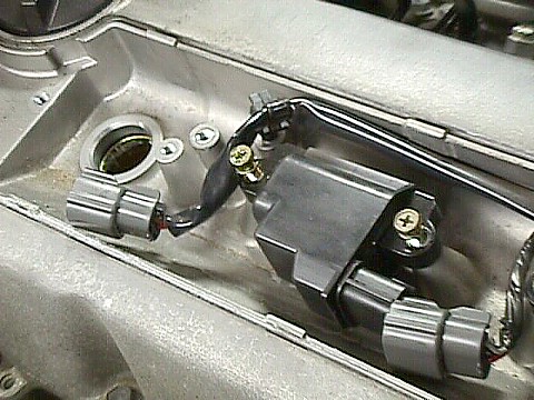
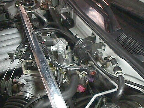
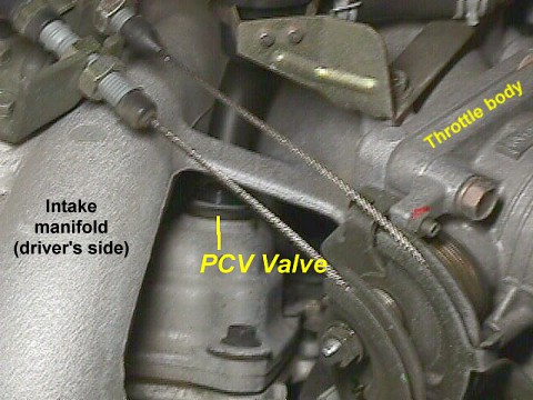
PCV Valve: The location of the valve is not longer a mystery. Located near the throttle body.
Belt Replacement: The ’95 has two accessory belts. One is the alternator and the other is compressor/power steering. This jobs took me over a hour to complete. You will need long combination wrenches and sockets. The sizes are 12 and 14 millimeter. Please note how tight the belts are because you have to adjust the belt accordingly. It’s call “deflection” so please push on the belts and remember. After the install you need to get the belts close to the same deflection.
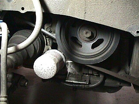
Take off the passenger side front wheel and the oil cover. This will expose the belts.
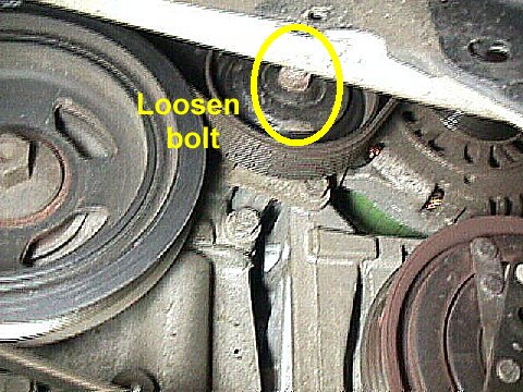
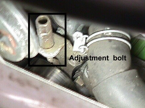
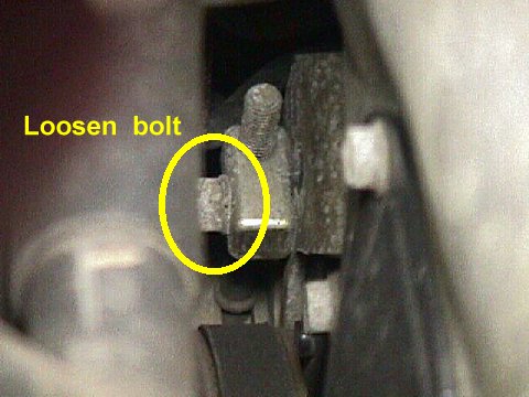
View from under the car. Looking at the center pulley. You have to loosen the bolt in the middle of the pulley. Then directly above is the adjustment bolt that you will loosen to raise the pulley. The next picture shows the top bolt.
View from the top passenger fender looking near time chain cover. Loosen the bolt so that you can raise the center pulley. This is the belt that needs to be removed first.
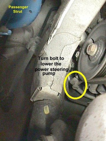
View from the top looking to the left. Loosen the bolt so that you can lower the power steering pump. There is a bolt on the other end of the threads that you can’t see. That bolt will lower the pump.
View from the bottom of the car. Tighten the bolt so that you can lower the power steering pump. The bolt is threaded into a clamp that when tightened the clamp closes, lowering the power steering pump.
Tighten throttle cable: Make sure the cable is low and in-between the half moon shape. The cable at the relaxed state should not be above the half moon…there needs to be more tension. The outside cable is your cruise control and the inside is your throttle. To fix this follow the cable about 6 inches back to two nuts. Loose the front nut and spin that forward, the cable will come loose but now you spin the back nut in the same direction and that will take up the slack along with securing the cable to the mounting bracket.
ECU reset: This is not needed for the 60K service. If the “check engine light” comes on. This is the proper way to reset it. Andi is the one who scanned the page.


")


")
")


")


")