Whenever people have a code that is related to an O2 sensor, they always have to figure out exactly which sensor that it corresponds to (bank 1 & 2 and sensor 1 & 2)….so I created this.
Description of O2 Codes
BANK 1 FRONT (Sensor 1)
P0031 – Heated Oxygen Sensor 1 Heater Low Voltage (Bank 1)
P0051 – Heated Oxygen Sensor 1 Heater High Voltage (Bank 1)
P0130 – Front O2 Sensor Circuit (Bank 1)
P0131 – Front O2 Sensor (Lean) (Bank 1)
P0132 – Heated Oxygen Sensor 1 Circuit High Voltage (Bank 1)
P0133 – Heated Oxygen Sensor 1 Circuit Slow Response (Bank 1)
P0134 – Heated Oxygen Sensor 1 Circuit No Activity Detected (Bank 1)
P0135 – Front O2 Sensor Heater (Bank 1)
P1143 – Heated Oxygen Sensor 1 Lean Shift Monitoring (Bank 1)
P1144 – Heated Oxygen Sensor 1 Rich Shift Monitoring (Bank 1)
P1148 – Closed Loop Control (Bank 1)
BANK 1 REAR (Sensor 2)
P0037 – Heated Oxygen Sensor 2 Heater Low Voltage (Bank 1)
P0057 – Heated Oxygen Sensor 2 Heater High Voltage (Bank 1)
P0137 – Rear O2 Sensor Low Input (Bank 1)
P0138 – Heated Oxygen Sensor 2 Circuit High Voltage (Bank 1)
P0139 – Heated Oxygen Sensor 2 Circuit Slow Response (Bank 1)
P0140 – Rear O2 Sensor High Input (Bank 1)
P0141 – Rear O2 Sensor Heater (Bank 1)
P1146 – Heated Oxygen Sensor 2 Minimum Voltage Monitoring (Bank 1)
P1147 – Heated Oxygen Sensor 2 Maximum Voltage Monitoring (Bank 1)
——————————————————————————————–
BANK 2 FRONT (Sensor 1)
P0032 – Heated Oxygen Sensor 1 Heater Low Voltage (Bank 2)
P0052 – Heated Oxygen Sensor 1 Heater High Voltage (Bank 2)
P0150 – Front O2 Sensor Circuit (Bank 2)
P0151 – Front O2 Sensor (Lean) (Bank 2)
P0152 – Heated Oxygen Sensor 1 Circuit High Voltage (Bank 2)
P0153 – Heated Oxygen Sensor 1 Circuit Slow Response (Bank 2)
P0154 – Heated Oxygen Sensor 1 Circuit No Activity Detected (Bank 2)
P0155 – Front O2 Sensor Heater (Bank 2)
P1163 – Heated Oxygen Sensor 1 Lean Shift Monitoring (Bank 2)
P1164 – Heated Oxygen Sensor 1 Rich Shift Monitoring (Bank 2)
P1168 – Closed Loop Control (Bank 2)
BANK 2 REAR (Sensor 2)
P0038 – Heated Oxygen Sensor 2 Heater Low Voltage (Bank 2)
P0058 – Heated Oxygen Sensor 2 Heater High Voltage (Bank 2)
P0157 – Rear O2 Sensor Low Input (Bank 2)
P0158 – Heated Oxygen Sensor 2 Circuit High Voltage (Bank 2)
P0159 – Heated Oxygen Sensor 2 Circuit Slow Response (Bank 2)
P0160 – Rear O2 Sensor High Input (Bank 2)
P0161 – Rear O2 Sensor Heater (Bank 2)
P1166 – Heated Oxygen Sensor 2 Minimum Voltage Monitoring (Bank 2)
P1167 – Heated Oxygen Sensor 2 Maximum Voltage Monitoring (Bank 2)
PLEASE KEEP IN MIND THAT PICS SHOW WASHER FLUID RESERVOIR WAS TAKEN OUT. YOU DO NOT NEED TO TAKE IT OUT, BUT I LEARNED THAT AFTER I TOOK IT OUT & SINCE IT WAS MY FIRST TIME DOING IT
Instructions
1) Open plastic cover from underneath the car, like you would do to change the passenger side fog light.
2) Now check to see if you see wire circled in the photo. This wire is needed to make the sensor work.
3) Now test-fit the sensor tube with wire.
4) Ok now to make sure it works. You need another person to help you with this step. Connect sensor tube. Now find a water bottle and cut the top off like the above pic, & fill it with water. Now turn the car on & dip the sensor tube in a bottle full of water. Now have another person check to see if your washer fluid warning light comes on your dash.
5) Now that you checked that it works. Have a bucket underneath & unplug the tube shown in the photo to drain any washer fluid in there.
6) Now look closely at the bottom left of the reservoir & you should see a sketched circle where the sensor tube should be.
7) Now take a 1 inch or 1 1/4 inch wood boring bit (I think that’s what it’s called) & drill a hole where the sketched circle is on the reservoir. Should look like the photo below.
8) As you can see in the photo I didn’t have a perfect circle. Because I believe the 1inch bit was too small but I just went round & round to make the hole bigger. *Don’t make it too big & test fit tube if need to. Should be a TIGHT fit for the sensor tube.*
9) Once the hole is big enough. Put on rubber around hole that came with sensor tube.
10) Now insert the sensor tube. Should be a tight fit!
11) Now with some silicone put it around the edges of the tube you inserted. This is just for extra protection that it won’t leak.
12) Now get wire & plug it into sensor tube & your DONE!!!
**To be safe I didn’t re-fill my washer fluid reservoir for a couple of days. Just to make sure the silicone completely dried.**
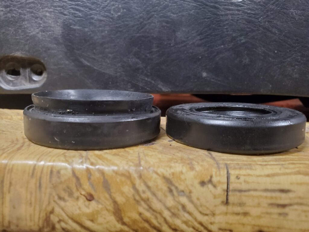
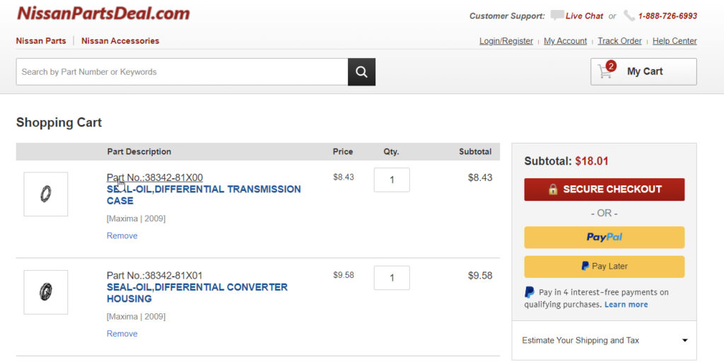
OEM Driver Side Part Number: 38342-81X00 Alternate Non-OEM Part Numbers: Timken / O’Reilly – 710118 Part Description: SEAL-OIL, Nissan Driver Side Output Shaft Seal / Differential Transmission Case Price: $8.00-$9.00
OEM Passenger Side: 38342-81X01 Alternate Non-OEM Part Numbers: Timken / O’Reilly – 710124 Part Description: SEAL-OIL, Nissan Driver Side Output Shaft Seal / Differential Clutch Housing Price: $8.00-$9.00
I have a 2009 Maxima SV with both electric tilt and telescoping functions. I am at 92k miles and recently my tilt motor stopped adjusting the steering wheel, I know, first-world problems here. I know the motor still worked because you can hear it moving what’s left of the gear.
I did some research and yes, you can buy a new motor from Nissan for $200. However, in my research, I ran into this product – Dorman 905-522. At this point in time, it’s a poorly made product and badly advertised as well. Nowhere, does it say that it’s compatible with 09 Maxima, though later Maxima’s are on the compatibility list. I saw a single review of this product on amazon and decided to take a plunge.
Yesterday, I had the “pleasure” of repairing my motor. So the product comes with new shafts and molded on Nylon gears as well as C-clips and some grease. It also comes with pretty good instructions on the actual repair.
Once you have the motor out, you follow a couple of steps from Dorman’s manual, specifically:
Take off the c-clip or locking the o-washer from the end of the shaft.
Remove a set screw/spring from the adjustment block (located on the side of the block, inner hex)
Unscrew adjustment block
Use the permanent marker to draw a line across the outer nut, inner locking nut, and body of the motor. This is necessary to apply the same preload to the inner bearings
Remove the large hex nut with a crescent wrench, it was not super tight. I used adjustable pliers to get it off.
Then slide the black spacer block included in the Dorman kit over the shaft, it should engage the inner nut. The block is square, but the nut has 12 points, so it will engage without any issues.
Spin the inner nut off
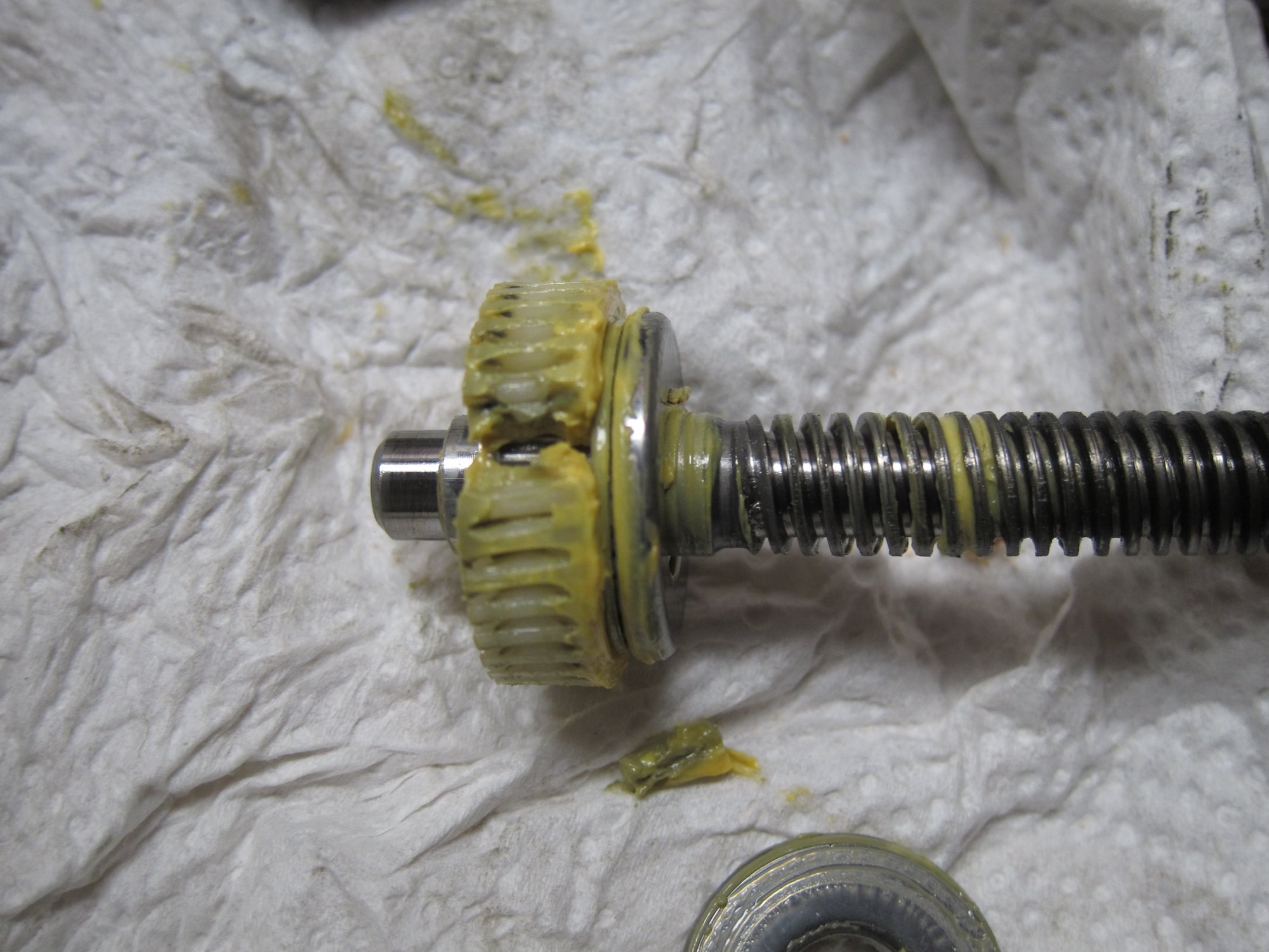
Remove old shaft, be careful, there is a bearing on the bottom and the top of the nylon gear.
At this point you should confirm that your old nylon gear is busted, mine had a whole chunk of gear missing. Assembly is reverse of disassembly.
But here is some bad news and good news.
Bad news first: When I tried to spin the adjustment block on the new shaft, the block was getting bound up in many spots, so there are problems with threads on these replacement parts. Since I have gone so far with the repair, I did not want to put the old broken part back in. What I did is used small files to file down the metal threads on the new shaft. I basically put some taper on the shaft threads and after about 2.5 hours of manual labor, the adjustment block would thread on smoothly without any issues.
Of course, it’s completely asinine to expect a person to file down metal threads to get the part to work. So here comes some mixed news that hopefully will turn into good news soon. This morning I contacted Dorman about my experience and they told me that they know of this issue and the product is supposed to have been put on hold with no further sales taking place until they retool and fix the issue. They were not able to tell me when the new product will be available, but hopefully soon. I left a 3-star review for this product on Amazon, and hopefully, when Dorman gets a new design done I will be able to update it to a 5-star review.
The good news is that there is no need to purchase $200+ new motors and throw out a perfectly good motor with broken plastic gear. The Dorman kit cost me $35 shipped from RockAuto, the kit includes both tilt and telescoping motor shafts. The R&R of the motor, given a proper shaft, is no more than 30 mins and that is taking things apart slowly. I can do it in 5mins now. For crafty guys, the threads on these shafts are M10 x 2.0. I don’t have a die or thread chaser this size, as a matter of fact, it’s a very oddball size that’s not easily gotten.
I do have some pics, but frankly, between the TSB and Dorman manual, you should have no issues taking things out and putting it all together.
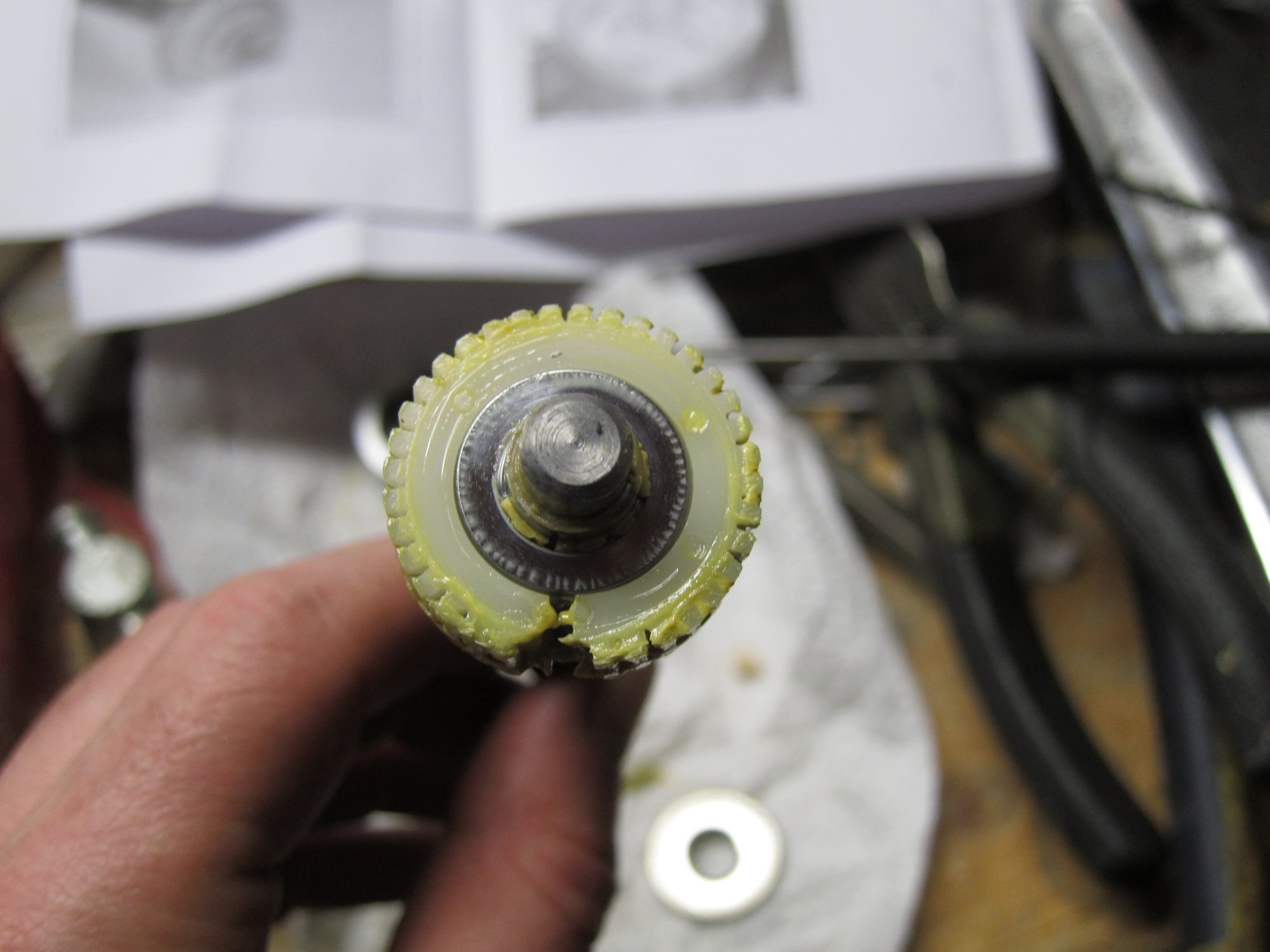
Old nylon gear broke, chunk of it is missing
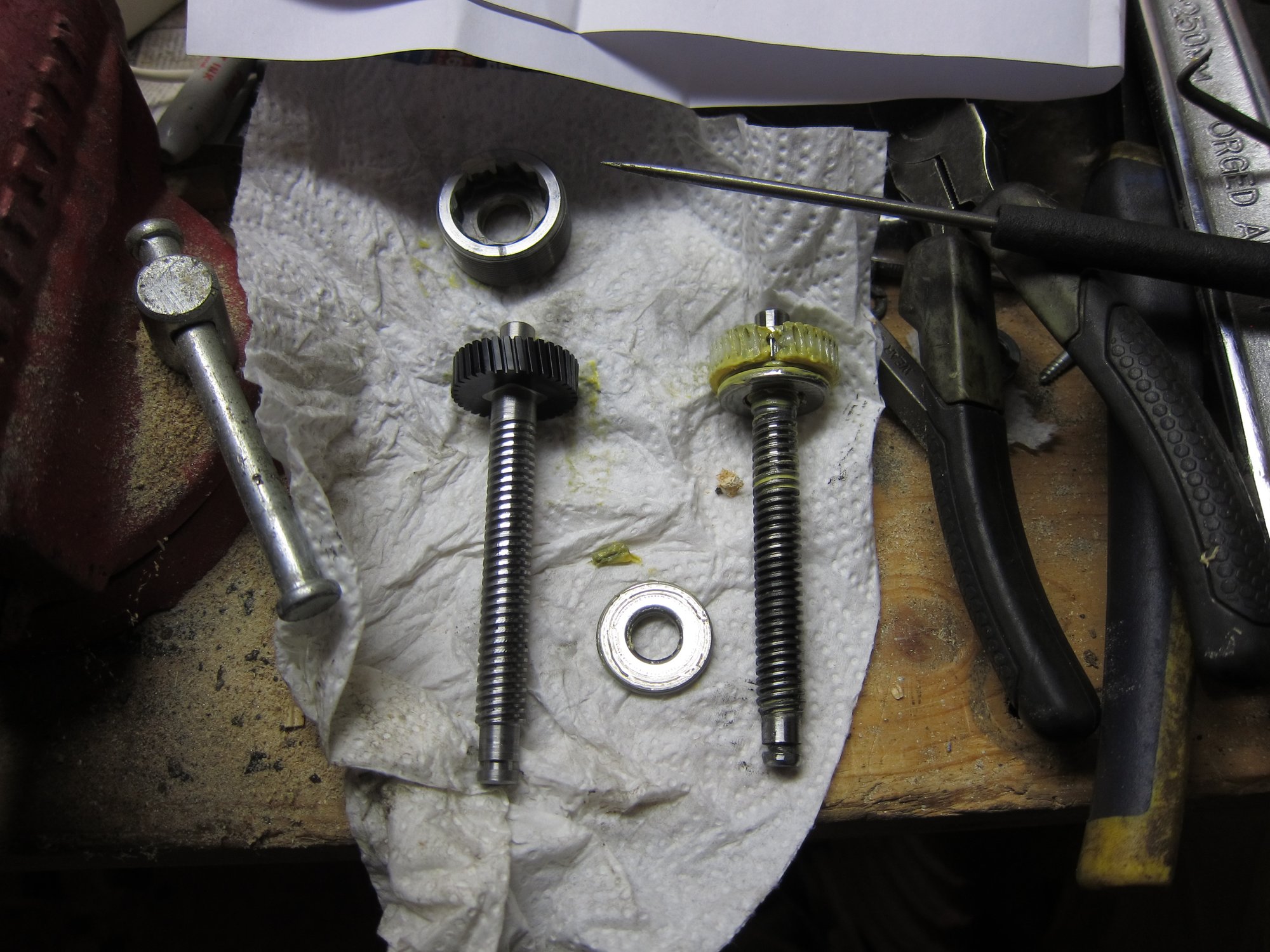
New Dorman gear side by side with old one
Old gear, notice that the shaft threads have a small taper to them. The gear also still has the bearing (shiny silver disk) still on it.
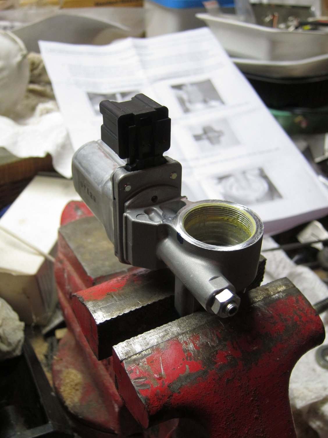
Tilt motor completely disassembled in the wise.
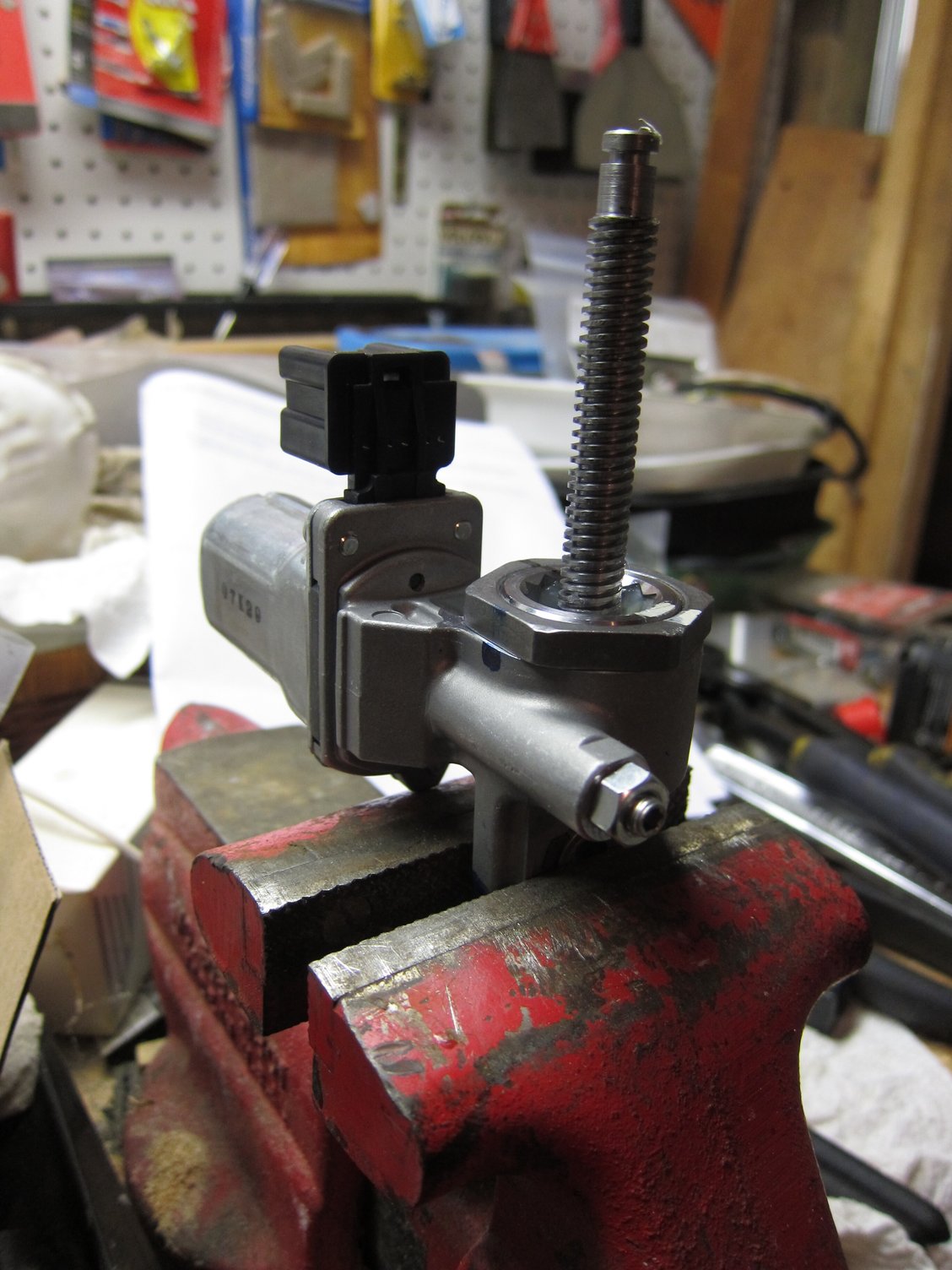
Tilt motor reassembled with new shaft.
Update
A follow-up on my repair. Sometime last fall I had an issue with my repaired tilt motor. One morning it just gave out, but the next day resumed its function. I opted to simply adjust the steering wheel and turn off the easy-entry function.
I was not sure what was wrong with the motor and thought that perhaps the motor itself is giving out. The telescoping motor died sometime earlier, don’t recall when exactly. After the initial repair in 2015, I did receive an “updated” part from Dorman in 2016. That kit was on the shelf until yesterday.
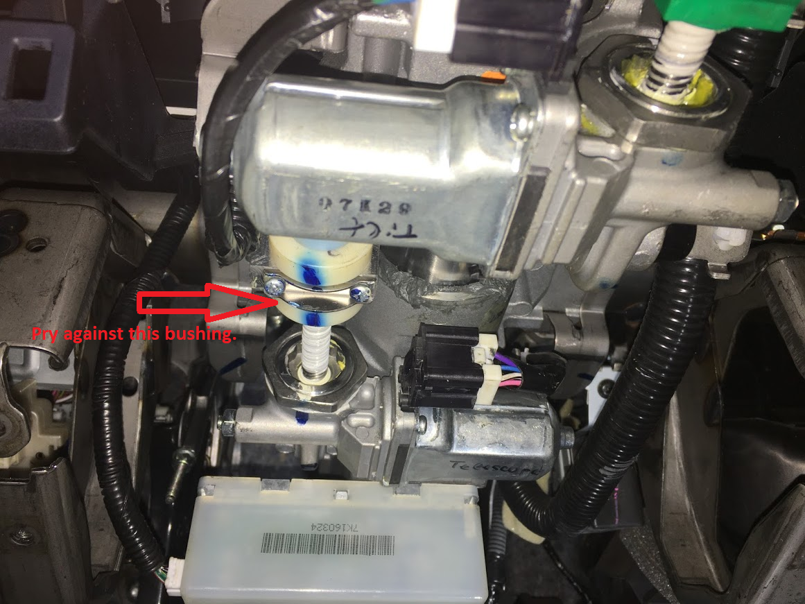
Since I got time on my hands, I decided to fix both motors. Followed my own links to get the motors out, but ran into an issue with removing the telescoping motor out. Mine died in a position that was very close to the dash, preventing easy motor removal.
The procedure explains that you want to pull on the steering wheel while actuating the motor to completely telescope/retract it out. I was not successful in that procedure. What I did instead was used a prybar between the white bushing and the rest of the steering column. It did not require much effort and applying prybar pressure while actuating the motor accomplished the task. Note that the motor had to be bolted in while performing the task.
On the positive side, I had no issues whatsoever with redesigned Dorman parts this time around. Both shafts were a perfect match for factory threads and no time had to be wasted to file anything down. I can wholeheartedly recommend the Dorman kit vs buying new factory motors or even salvage ones. Again, the most important part is to mark the relative position of how parts are put together prior to disassembly. After replacing the shafts, just realign things to the marks that you made and preloads will be perfect.
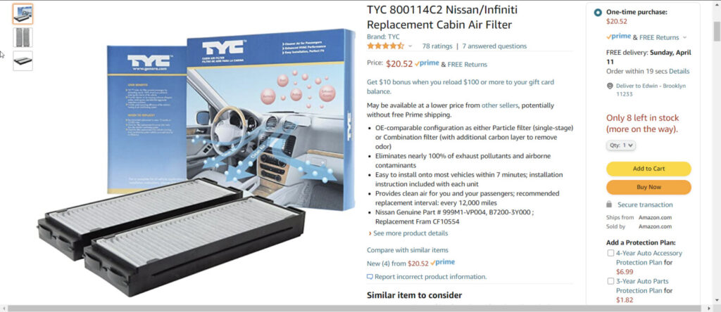
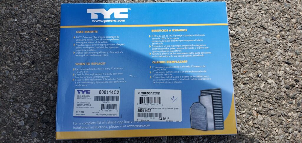
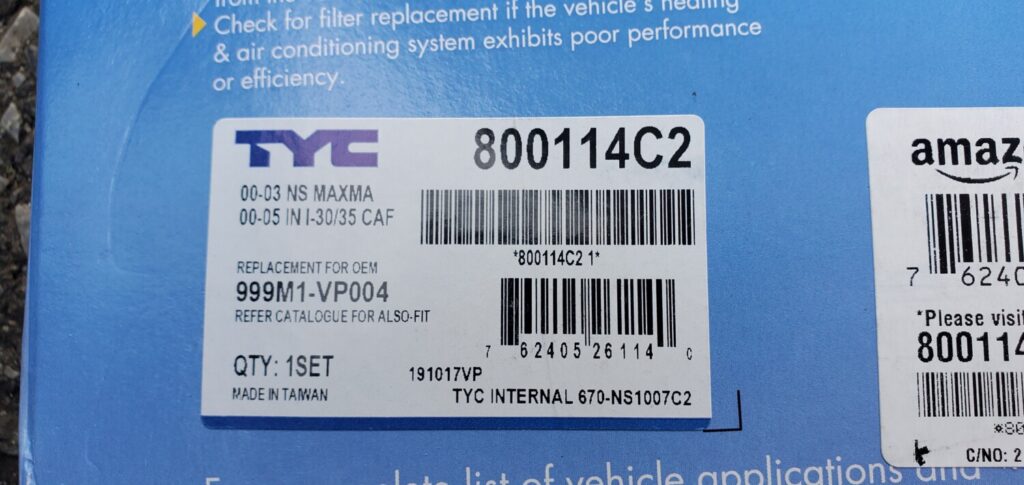
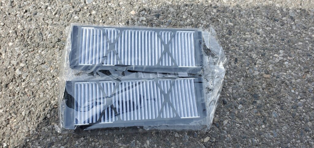
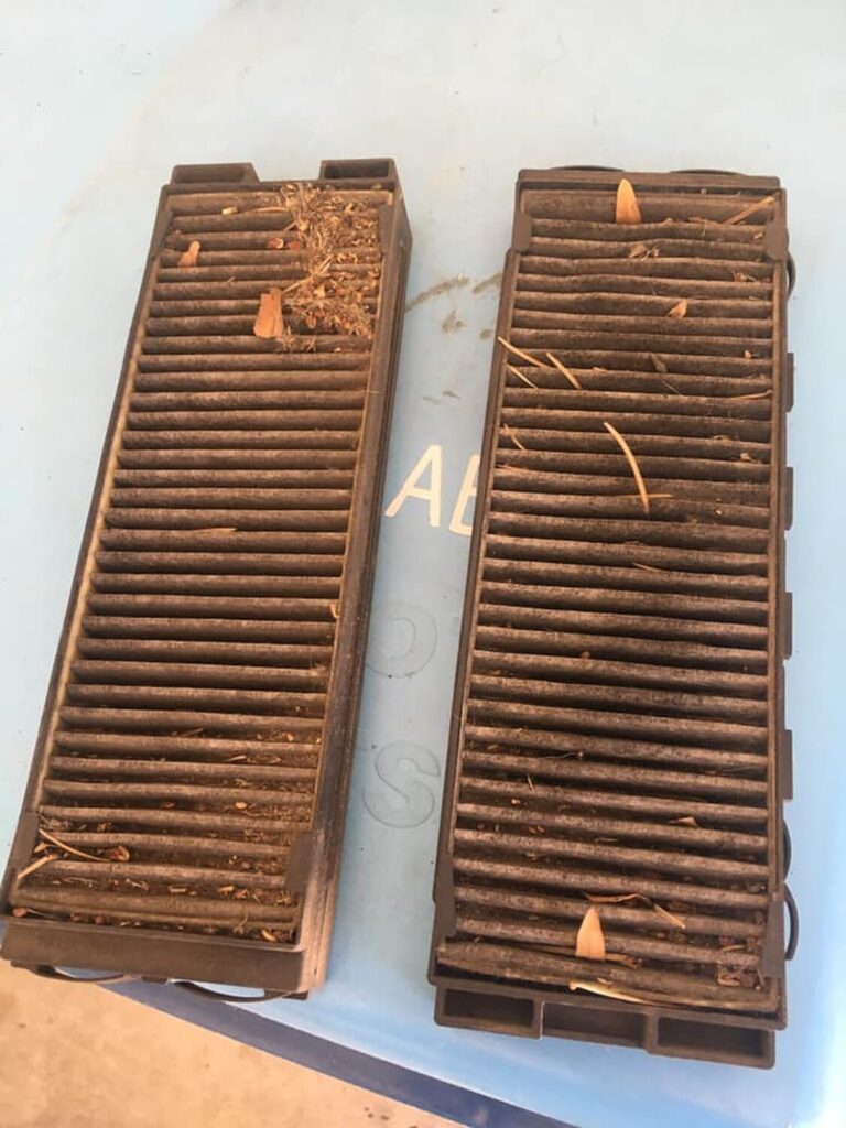
I was changing the blower motor on my car and decided to change the cabin filter. When I took out the cabin filter I noticed it was two pieces. I found TYC 800114C2 on Amazon for $20.00. It had solid good reviews so I went with this one. Looks like the OEM one is 1-piece but I decided to stick with the 2-piece I already had.
Why change it?
A dirty air filter can certainly impede your air conditioner’s ability to cool and after time could cause unnecessary strain on the entire system.
Avoid reduced air circulation inside your passenger compartment
Avoid diminished heating and air conditioning performance
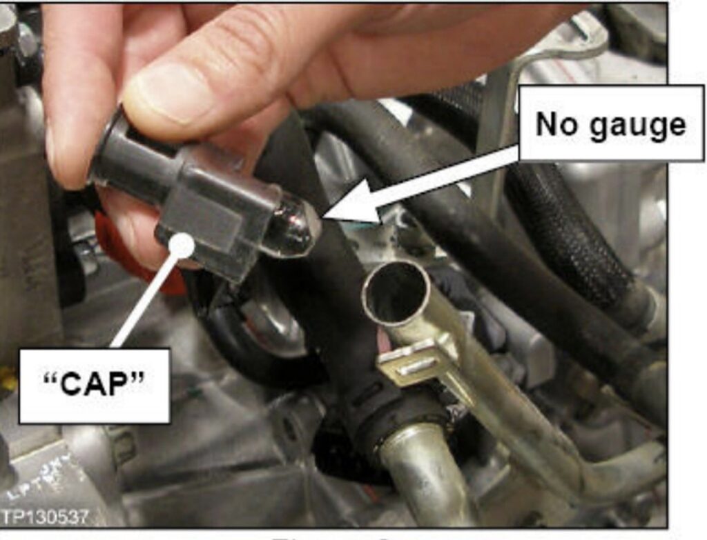
The 2016+ 8thgen Nissan Maxima does not come with a dipstick to fluid levels, unlike other generations. All new CVT transmissions from 2013-up are equipped with locking dipstick caps but no dipstick, with some Sentras and Versas being the exception to the rule. This was done to prevent the layman from screwing with fluid, etc.
Nissan service manual recommends changing CVT fluid when CVTF deterioration date is 210,000. The only way to check CVTF deterioration is through Consult-III+ scan tool. You can also do this with a CVT app on Android phones. The app is called CVTz50 and costs $5 bucks. You can read more about it here.
However, there is a way to check the fluid level. The service manual directs you to pump 2-3 quarts of NS3 into the overfill plug on the underside of the transmission. Not everyone has this fluid pump (ie. anyone that doesn’t work in a Nissan dealership.) The way around this is just to dump the fluid in through the dipstick tube with a funnel. It’s the quickest and easiest way around not having the fluid pump. The goal is to overfill the transmission by a quart or two. Next, you’ll have to hook up some kind of scan tool that can read transmission fluid temperature. The only way to monitor proper fluid level is by reading transmission fluid temp.
Hook up your scan tool, get the data monitor ready to view transmission fluid temp, and start the vehicle. Allow it to idle for ~10 seconds. While holding your foot on the brake, shift to reverse and hold it for ~5 seconds. Shift through all of the gears in this manner with your foot still on the brake to allow the fluid to work its way through the control valve assembly and all oil passages. This will ensure that the fluid in the pan is at the correct level. Shift back into park.
After you’ve done this, wait for the transmission to warm up to 95 degrees Fahrenheit. At this point, remove the 14mm overflow bolt on the bottom of the transmission. Fluid will begin to pour out, so be prepared. Monitor fluid temp while watching the CVT fluid flow from the overflow tube. Verify that the fluid slows to a fast “drip” before transmission temp reaches 113 degrees Fahrenheit. 95-113F is your temperature adjustment window. Once the fluid has slowed to a fast drip, install the overflow plug and you’re on your way!
In the event that the transmission was “too” overfilled and CVT fluid flow from overflow tube doesn’t slow before 113F, reinsert the overflow plug and allow the transmission to cool down. Lather, rinse, and repeat the above procedure.
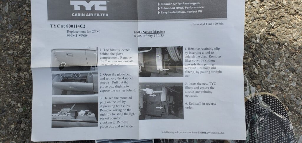
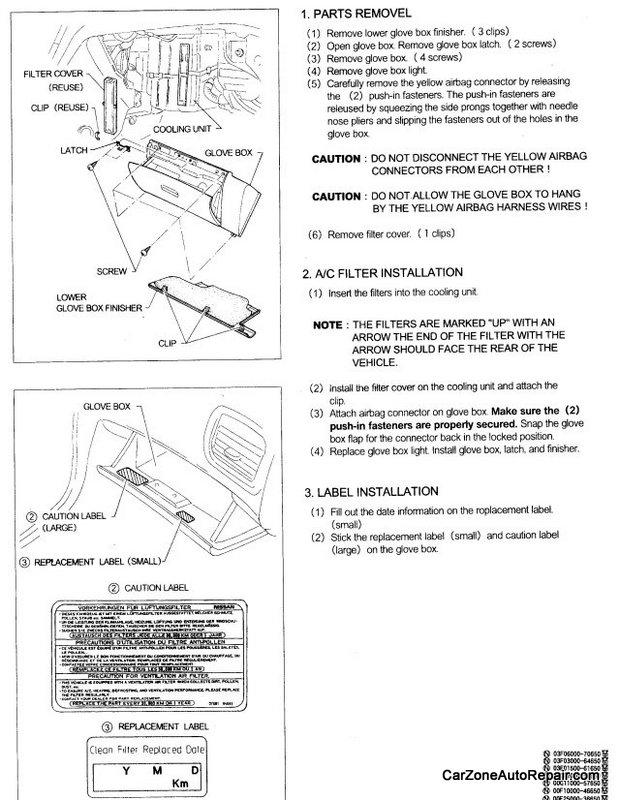
These are the Nissan-Supplied instructions for the In-Cabin Microfilter. They are somewhat generic and were not 100% accurate to my car. The only difference was that my car did not have the “Glove Box Finisher”. Besides that, everything else was correct. Perhaps the Glove Box Finisher was eliminated in later 5th-Gen Maximas?
I bought my filter at a Nissan Dealership. The cost for one of these babies is $58.74!!! Cheaper deals can probably be had on the Internet.
Nissan recommends changing this filter approximately once per year. This procedure is not listed in the owner’s manual, as Nissan prefers this operation be dealer-installed. With only a Philips screwdriver, if you are the least bit competent you can do this job yourself and save money. The filter alone is expensive enough!!
Instructions:
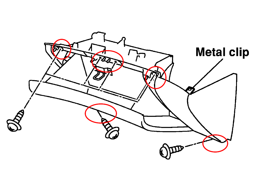
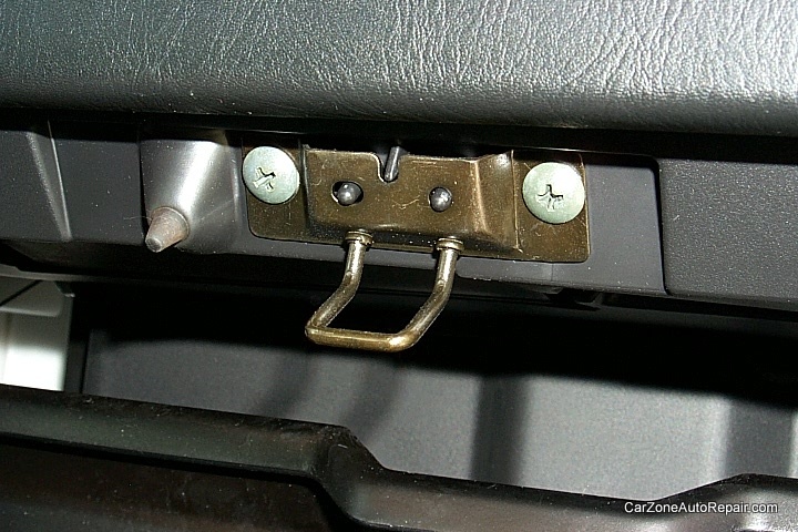
1. Start by removing the glove box latch. 2 screws and it’s out.
2. Next, remove the 4 screws holding the glove box in place. There are 2 at the top and 2 at the bottom. You will have to disconnect the glove box light and the airbag connector. Both come off easily, and the entire glove box can be removed.
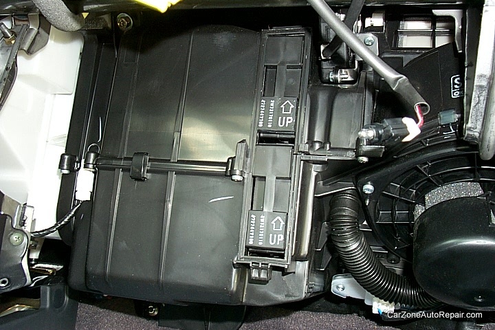
3. Once the glove box is out, the next step is to pop off the metal clip holding the white filter cover in place.
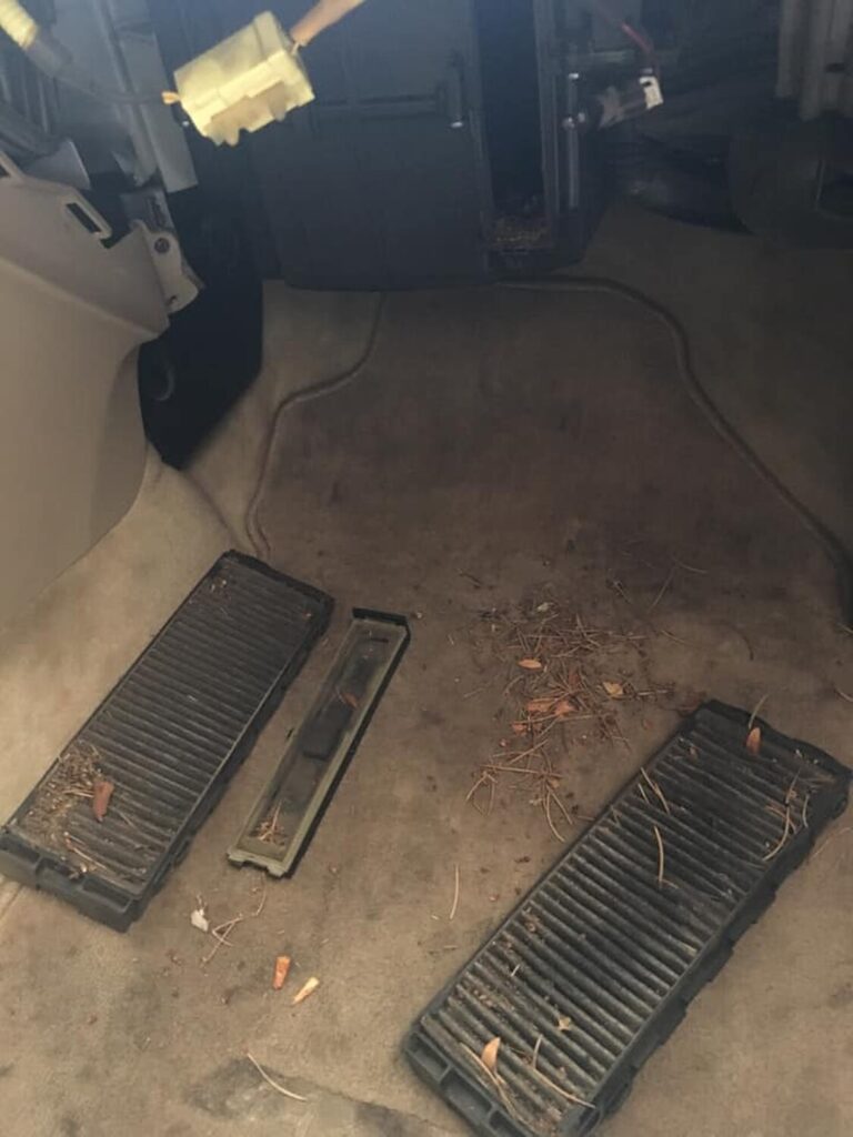
4. Now the filter can be slid out. Apparently, the microfilter put in at the factory is a single piece, and does not look like the factory replacement filters you will put back in. In fact, the replacement filters look much nicer (higher quality). This picture shows the empty hole where the old filter was.
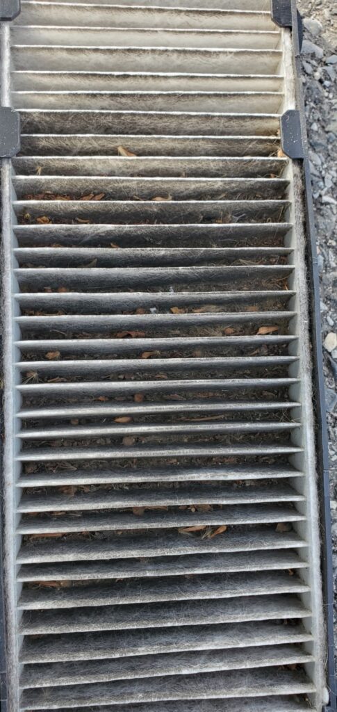
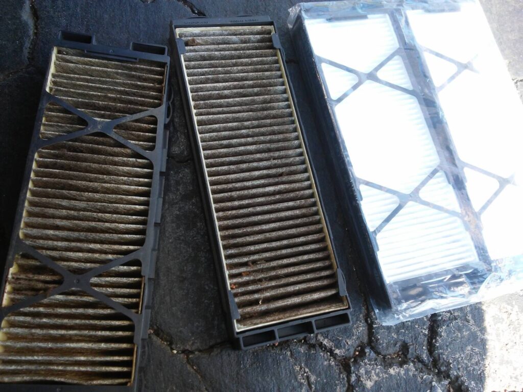
5.This side-by-side shows the stock filter removed on the left, and the replacement filters on the right. I was quite amazed at how dirty this filter got. The replacement filters come in two pieces and have plastic holders that enable them to slide into place more easily than the original filter.
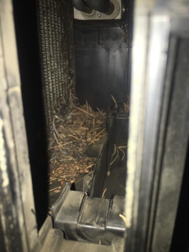
My filter had all sorts of black dirt, crud, and leaf pieces in it!!! And I keep this car garaged, and never drive it in the rain (if I can help it).
6. The easiest way to get the new filters in is to put one in at the bottom, then once it is in, slide it up into the top position, since it is difficult to get the proper angle to put the top one indirectly.
7. Here is the completed filter installation, with both filters securely in place. Replace the white filter cover, glove box, reconnect the light and airbag connectors, and this installation is complete. Ahhhh, fresh air to breathe once again.
Community Member Credit: Ezekiel-Adrenaline Persad
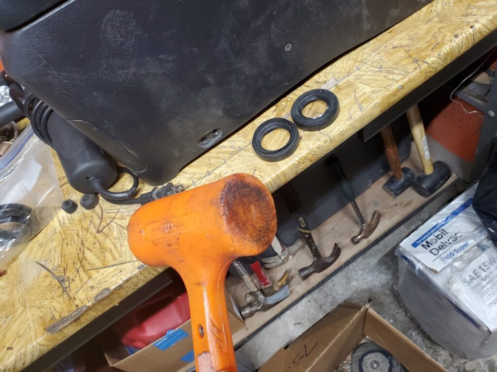
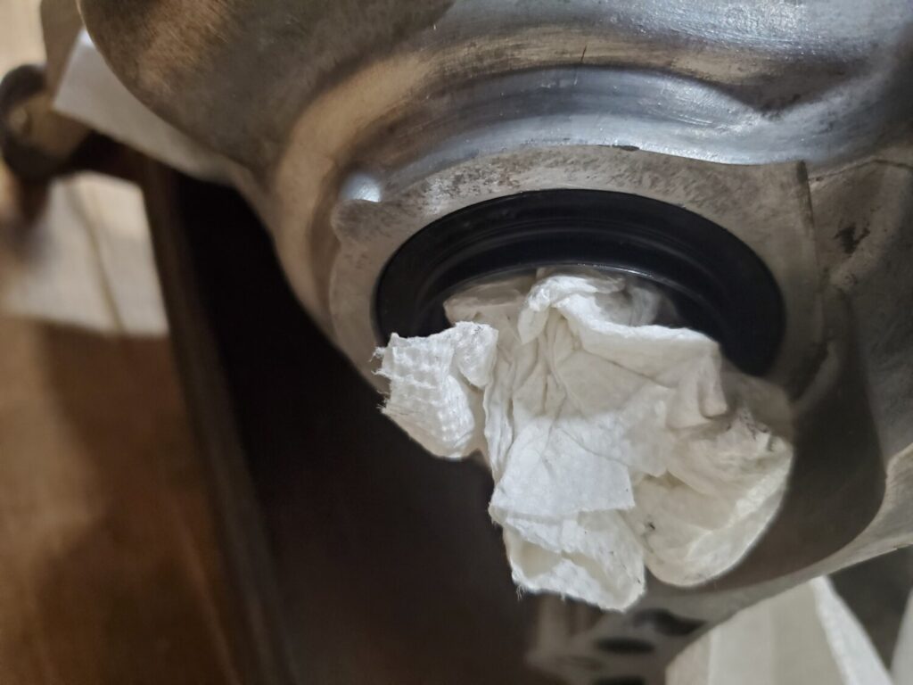
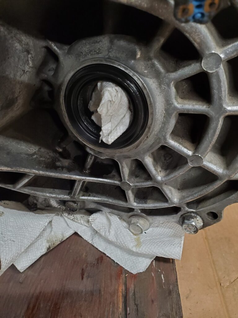
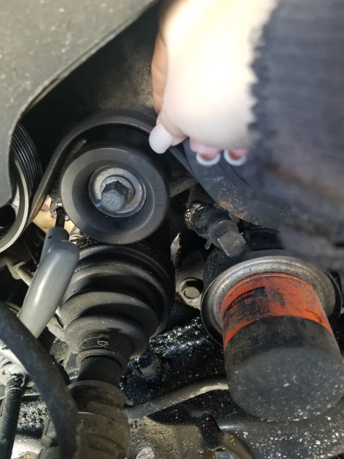
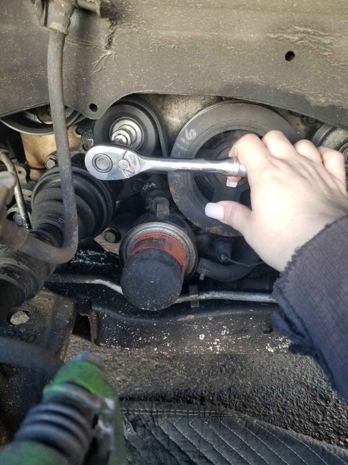
Just installed my diff seals for the axles. I don’t have a puller/installer kit so I’ve used a few ways to get these in there. Just sharing this if you don’t have the kit either. You can just use your old seal. Cut off the lip and you can hammer on it. Just place it over the new seal and send it no damage, easy, and free.
2. Remove the 4 screws holding the the glove box, two at the top and two at the bottom
3. Once the screws are removed pull out the glove box. You may need to use a crew driver to undo the right/top clip.
4. With the glove box removed, you will be able to see the “Fan Control Amplifier” for automatic air condition system or “Blower Motor Resistor” for the manual system.
5. Remove the 2 screws holding the Amplifier/Resistor, pull out the Amplifier/Resistor and install the new one.


")


")
")


")