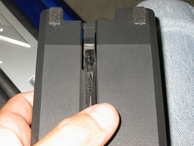
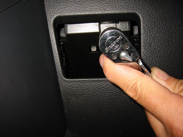
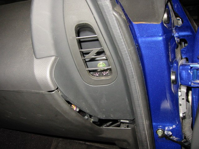
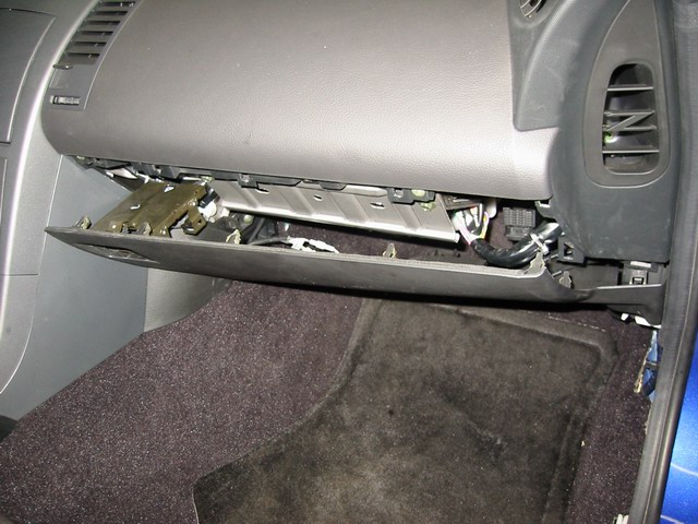
I’ve seen a lot of people asking about how to clean the MAF, so I decide to do my own and show it to them.
Things you need during the cleaning:
CRC MAF cleaner
Torx screwderiver #15
10mm wrenchPreparation:
Park your car under a shade or a place that isn’t dusty.
Disconnect the bettary using the 10mm wrench to avoid damaging the ECU.
Location:
The Mass Air Flow sensor is located on a tube between the engine filter box and the throttle filter.
Remove the MAF:
1. Clean the area around the MAF and blow away the dust on it.
2. Press the clip on the socket and pull upwards to dissconnect the MAF.
3. Unsrew to screws that hold the MAF using the Torx screwderiver #15. Pull the MAF upwards to remove from the housing. If it’s difficult to pull it out, twist the MAF 90 degree, so you can pull it out with your both hands.
4. Remove the MAF carefully from the housing and make sure you don’t drop it. Clean the housing and cover it with a damp towel to prevent dust getting in.
Clean the MAF:
1. A MAF has two air tunnels on it, so you have to clean both of them.
( red arrows show how air flows through the MAF)
Only 5.5th gen has this intake air temp sensor, 5th gen has seperated one.
2. Take you MAF cleaner and put the pipe on it, so you can reach small areas. When you clean the MAF, DO NOT touch anything in side the tunnel with the pipe because that can damage the sensor.
3. Keep blowing the cleaner for 2-3 seconds to each tunnel, and you can also clean the resistor at the same time. After cleaning the MAF, let it sit for 15 minutes to dry. I prefer to put it like this, so dust won’t get in.
Reinstall:
When you put the MAF back, just make sure the air flow direction is correct, with two tunnels/holes facing to the air filter.
Relearn procedure:
After putting the MAF back to the car, perform the ECU reset and Idle relearn procedures.
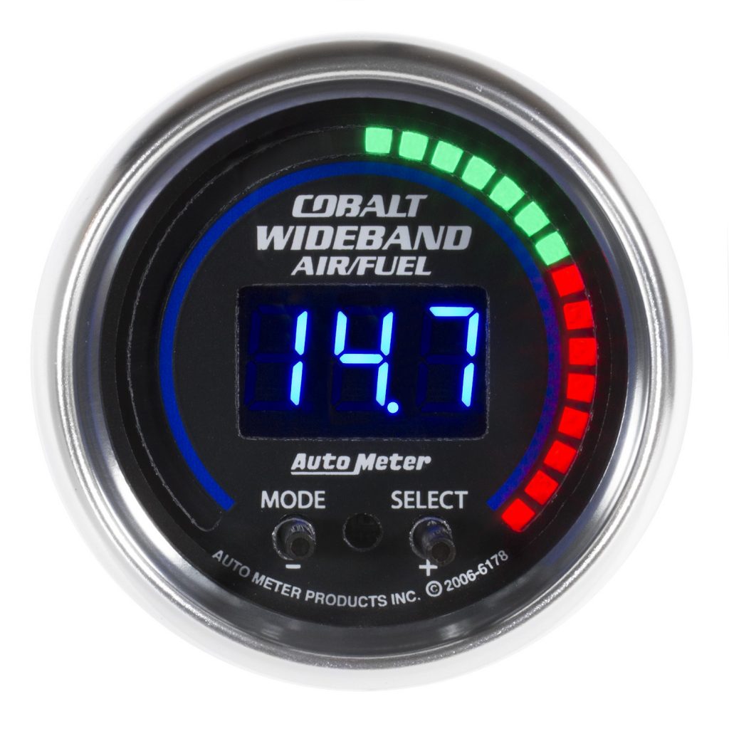
Air Fuel Ratio (AFR) is the ratio of air to fuel in an internal combustion engine. The AFR is an important measure for performance-tuning reasons. If exactly enough air is provided to completely burn all of the fuel, the ratio is known as the stoichiometric mixture which is defined as an 14.6 AFR ratio. The lower the AFR the richer the mixture. The higher the AFR the leaner the mixture.
6 AFR – Rich Burn Limit (engine fully warm)
9 AFR – Black Smoke | Low Power
11.5 AFR – Best Rich Torque at Wide Open Throttle (WOT)
12.2 AFR – Safe Best Power at Wide Open Throttle (WOT)
13.3 AFR – Lean Best Torque
14.6 AFR – Stoichimometirc Air/Fuel Ratio Value (Stoich)
15.5 AFR – Lean Cruise
16.5 AFR – Usual Best Economy
18 AFR – Carbureted Lean Burn Limit
22+ AFR – EEC / EFI Lean Burn Limit
IDLE / LIGHT CRUISE: 13.5 AFR
When you start your vehicle we refer to this as being in IDLE condition. When you shift into gear and drive at a low mph we refer to this as being a LIGHT CRUISE driving condition. With 14.6 being the industry standard stoich AFR value, we typically like to see these conditions run slightly richer. We are looking to fine tune an engine to get the smoothest operation.
CRUISING: 14 AFR
Most of the time you are driving your vehicle you will be within the state of CRUISING. This condition is the most wide open for customer preference based on two factors. If you prefer better GAS MILEAGE then run a leaner mixture. Most stock to slightly modified engines will run just fine at an AFR of 15 and yield better MPG. If you prefer better PERFORMANCE then we suggest to run an AFR of 14 or even richer to around 13.
WIDE OPEN THROTTLE: 12.5 AFR
Driving full out within a gear will bring you into a WIDE OPEN THROTTLE driving condition. This condition is where the peak horsepower value is obtained. We typcially like to run a richer AFR here to get the best performance. Best performance for most vehicles is in the 12.5 to 13 AFR range. Going too rich will have the opposite affect and decrease your performance.
ACCELERATION: 12 AFR
Getting up to cruising speed or getting ready to pass someone, you usually are looking for the performance to get up and go. We refer to any fast turn of the throttle as being in an ACCELERATION driving condition. Again, we typcially like to run a richer AFR here to get the best performance. Best performance for most vehicles is around 12 AFR. Going too rich will cause a sluggish roll-on to get up to speed.
NOTE: OPTIMAL AFR VALUES WILL CHANGE BASED ON FORCED AIR INDUCTION VS NATURALLY ASPIRATED AND FUEL TYPES
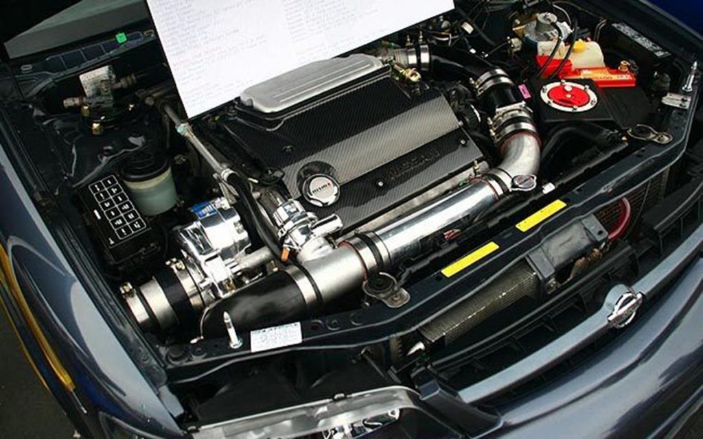
Why? So that one of the bends of the 2.5″ charge pipe can be eliminated (the retarded chamfered elbow) and ease of configuration for those who want to upgrade to a 3″ charge pipe system. Re-clocking the blower also gets the charge pipe away from the back of the headlight and allows a lot more room for those who do headlight retrofits. (My chamfered elbow was rubbing my OEM headlight bulb connection and causing it to flicker on and off)
Keep in mind that if you’re keeping the 2.5″ charge pipe that originally was provided in the Stillen kit, then you’ll have to cut off a portion at the end of the charge pipe (at the second bend near the SC mounting plate) and get a new silicone 90 degree coupler (2.75″ to 2.5″) to reconfigure the system. If you’re upgrading to a 3″ charge pipe, then you’ll have to buy quit a bit more including: piping/couplers/your choice of BOV, Maf adapter etc.
Where? In your car, blower fully installed and mounted to the engine. It’s a common misconception that the blower must be removed from the car in order to re-clock the blower. You do not have to take the blower off the car, unless you run into the problem stated in the disclaimer below. This probably goes without saying, but re-clocking the blower while installed in the car allows you to fine tune and find the perfect angle in such a way that the 90 degree silicone elbow is situated just right and allows proper hood clearance. If the blower was removed from the car, then you’ll be taking the trial and error approach and burning a lot of time taking the blower/plate on and off/re-clocking the blower in order to find the perfect angle.
Here’s how the blower looks as Stillen/Vortech intended (2.5″ charge pipe, two bends at/near blower outlet)
Here’s how the blower looks re-clocked (3″ charge pipe, one 90 degree bend)
Here’s how to re-clock (rotate) your blower
Pic 1Pic 2
Look near the oil feed fitting and you’ll see a hold down plate and two allen screws. (See Pic 2) Keep in mind, there is still one more hold down plate and two screws to locate. See pic 1 for both plates (outlined in red) and all 4 screws (noted in green). Although the blower is installed in the car and space is limited, you should have no problem getting to the plates and allen screws. The hold down plate and screws holds the scroll to the blower itself. Loosen the screws quit a bit until you are able to re-clock (rotate) the blower’s outlet. You can remove the screws and hold down plates if you find it easier or the scroll isn’t rotating freely. Now re-clock the blower’s outlet to the desired position. Tighten the allen screws to prevent any further rotation and snug things back up the way they were. If you removed the 4 allen screws and 2 plates, reinstall them at this time.
* Some people have reported that they have 5 screws and 3 hold down plates. If you can’t re-clock the scroll after undoing/removing the 4 screws and 2 hold down plates as stated above, then look for a fifth screw and small hold down plate. This small hold down plate is only slightly bigger than the screw head itself. This 5th screw and small plate is noted in blue in Picture #1.
Disclaimer: Some people have it easier than others. Some discover that one of the plates is easily accessible (12 o’clock position) while the other is impossible to get to (6 o’clock position) while the blower is installed in the car. If this is the case, you may have to remove/uninstall your blower from your Maxima to gain accessibility to the hidden plate and screws. If so, feel free to relocate the plate and screws to a more accessible location anywhere around the perimeter of the scroll. Just keep in mind, that wherever you install one plate, the other plate should be on the opposite side of the scroll. When I re-clocked my blower, I had it easy. Both of my plates and 4 screws were easily accessible (3 o’clock and 9 o’clock position) [Positions are based on the individual standing at the passenger side of the car and looking at the blower]
Seafoam is a 100% pure petroleum product for use in all gasoline and diesel type engines, both 2 and 4 cycle. OXYGEN SENSOR SAFE. Cleans dirty engine parts internally by removing harmful gums, varnish and carbon. WORKS AND PERFORMS INSTANTLY.
Removes moisture from oil crankcases and fuel tanks.
Stabilizes and conditions fuels. Use for engine storage.
Cure hesitations, stalls, pings and rough idle due to carbon buildup.
Helps pass emissions test. EPA Registered.
Important Note: Run the seafoam in your oil for NO MORE THAN 250 miles! Seafoam is very aggressive. Your next oil change will be black as satan’s heart and likely thicker than usual. I would not recommend running this oil very long in the car as your oil filter is going to have quite the time on its hands and the oil won’t be in the best of shape afterwards. I’ll say it again. change your oil less than 250 miles after you put seafoam in your crankcase! I recommend running it 100 miles, then changing your oil. that should be plenty for the seafoam to get most of the gunk out.
How to change your Cabin Air Filter
IMPORTANT NOTE: The in cabin air flow is TOP to Bottom, in the Video I incorrectly stated the direction of the arrow should point for an aftermarket filter! If using a NISSAN Filter they show an arrow in the middle of the filter stating this side up while off to the right of the filter it shows and arrow pointing down stating direction of Air Flow. For an aftermarket filter it has an arrow in the middle which shows an arrow with the direction of air flow so for aftermarket filters the filter needs to be turned over and the arrow face down. It won’t break anything so don’t freak out just wanted to point out the difference.
Are you noticing a lack of power when accelerating between 0-40 MPH? Is your car fine once you get passed 40 MPH? Did you scan for codes and nothing? Do you have a CVT?
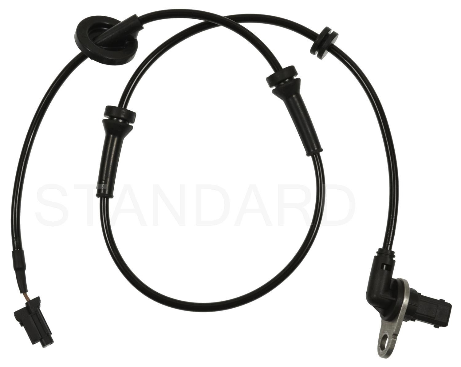
If you answered YES to the questions above, then you may be experiencing a common issue on the CVT Nissan Maxima where you have a faulty ABS/VDC wheel speed sensor. Nissan has published Service Bulletin NTB11-089 to address this issue on the 2007-2012 Nissan Maxima.
You may think that your CVT is going bad? However, many have had their CVT transmissions replaced and still had the same problem. Start by checking your ABS/VDC wheel speed sensors first.
You can download the Service Bulletin by clicking the link below in case you want to show it to your Nissan Dealer or Mechanic.
The most likely cause of the above concern is an issue (sensor, wiring, or debris on sensor/rotor) with the output signal from an ABS/VDC wheel speed sensor.
A weak or erratic output signal from a wheel speed sensor can cause poor performance or lack of power from a stop, or at low speeds.
Do not replace the TCM or CVT unit when repair of a signal from a wheel speed sensor will resolve the issue.
How to Fix it?
Inspect and replace the ABS Wheel Speed Sensors. You may not need to do them all, but the sensors are fairly inexpensive. You have two options, Dealer or eBay. Seems like many folks have have had success with the eBay ones and you can get all four for $50 bucks shipped. Yeap that’s right ALL FOUR!
However, for all electrical parts we always recommend OEM.
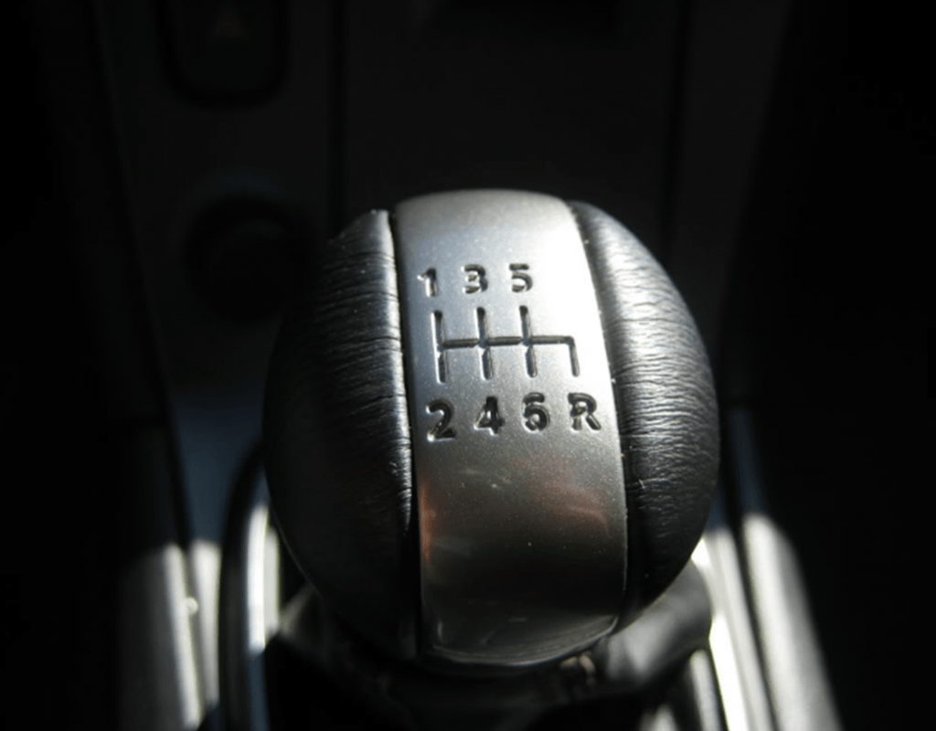
Note: This how-to is for ’02-’03 Maxima’s with a 6-speed transmission.
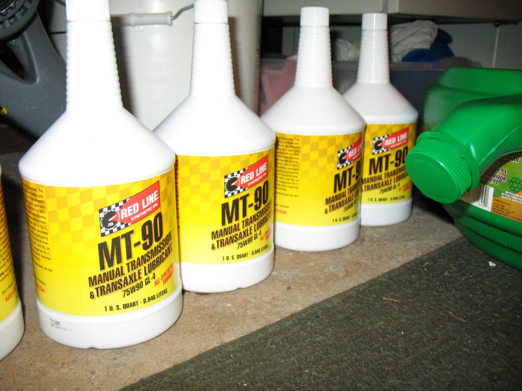
I ordered 3 quarts of Redline MT-90 Manual Transmission fluid from myoilshop. Their service was quick – I received the oil on 1-17. Redline MT-90 is a quality GL-4 fluid. Amsoil Series 2000 SAE 75W-90 Synthetic is another popular choice. The important part is to only use GL-4 for Maxima’s.
Redline claims MT-90:
– Improves shift feel, particularly in cold weather
– Eliminates notchy shifting
– Enables high-speed downshifting
– Perfect synchronizer coefficient of friction
– Eliminates gear whine and rattle at high temperatures
– Non corrosive toward synchronizers
– High performance gear protection
Many on Maxima.org have found the above to be true.
The 02-03 Max takes a little less than 3 quarts, much less than the old 5-speeds. With the proper tools, the process is pretty straightforward and takes about as long as a normal oil change.
Tools:
Oil pan
3/8″ socket
3 qts. of GL-4 Manual transmission fluid
Plug Gaskets (2) – I didn’t replace mine because these aren’t crush style gaskets. I’ve had no issues with leaking since the swap. As long as they aren’t damaged you should be able to reuse them without a problem. However, to be safe, you may want to switch both the drain and fill gaskets. Nissan part #11026-4N200. In my area these ran between $2.25 and $6.50 a piece. For a little piece of metal? Ouch.
10mm hex drive. Not in the “Average Joe’s” tool kit. I purchased the hex drive socket at Wal-Mart.
Funnel with at least 22″ of hose. I purchased two separate funnels with hoses from Wal-Mart to get the necessary length.
Socket with Hex drive:
2. Put car on stands/ramp. This is optional – some have had luck with the car flat on the ground, but I prefer a little extra room to work. It’s very difficult to reach the fill hole with the car on the ground.
3. Remove both plugs.
The drain plug is at the bottom of the transmission. Remove the plug with the 10mm hex drive socket. The plug was extremely tight in my case.
The old fluid will be dark brown. Mine smelled nasty – even with only 30k miles. After around 15 minutes the dripping stopped. The fill plug is toward the top of the transmission.
Both the fill and the drain plugs are visible in this shot. This shot is taken from the front driver’s side facing toward the passenger side:
4. Route funnel with hose down into the fill hole. This can be done while you’re waiting for the old fluid to completely drain. Funnel in position:
5. Replace drain plug.
6. Fill with new fluid.
Make sure to keep an eye on the end of your hose. I placed a quart upside down in the funnel and stayed under the car to make sure the hose didn’t slip out of the fill hole. The transmission is full when the fluid starts to come out of the hole. You should be able to put your finger in the fill hole and feel the fluid flush with the bottom of the hole.
Fill hole dripping since it’s full:
7. Replace fill plug.
8. Enjoy crisper shifts and the peace of mind that comes from synthetic protection. I’ve heard some suggest that the next 500 miles after the change are a “break in” period. Try to avoid hard shifts during this time.
The pictures are from a 350z but you can see its just about the same exact procedure for a 6thgen.
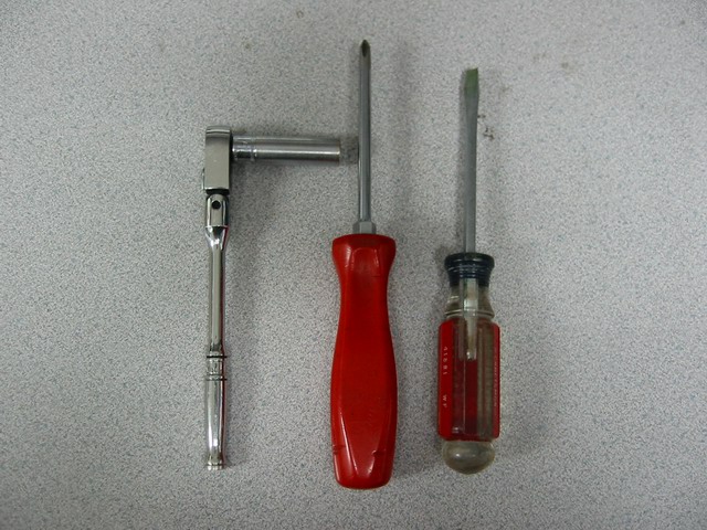
Tools required for ECU removal and re-installing.
1. 10 mm socket and ratchet (or equivalent)
2. Philip (cross) screw driver
3. Flat head screw driver
Before you start lower your driver and passenger side window down about 1-2 inches. You can lower it more, but at the very minimum 1-2 inches. This is done so when you disconnect your battery the doors will open smoothly.
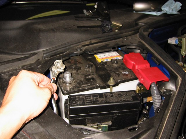
Start by disconnecting the battery by removing the negative terminal using the 10 mm socket.
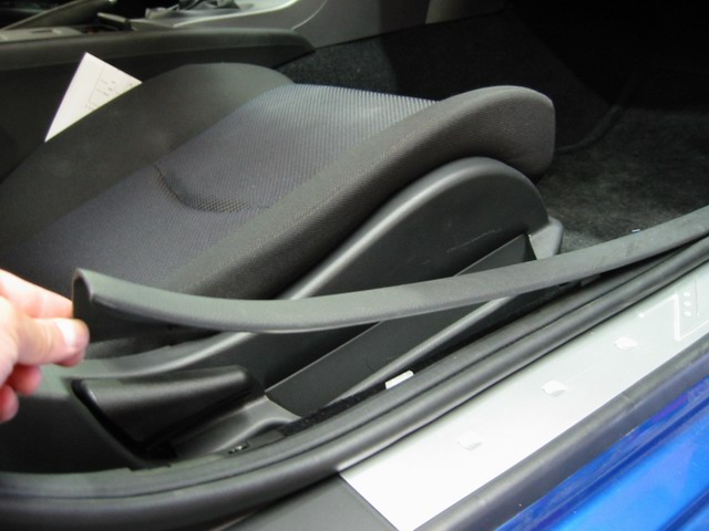
Next open up the passenger side door and remove the floor/doortrim by gently pulling upwards. Start from the rear and work towards the front.
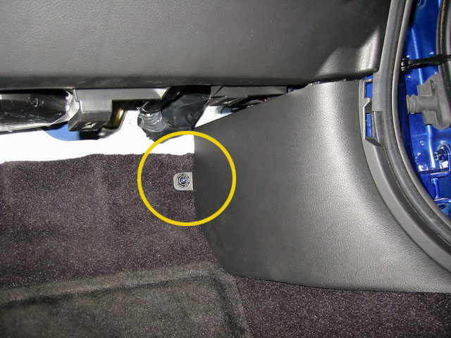
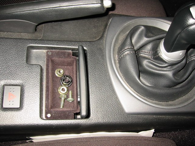
Find the plastic nut that holds the side kick panel. Remove it by turning counter-clockwise. No tools are needed. It’s not on very tight. Put all loose hardware (nuts, bolts) into the tray behind the shifter.
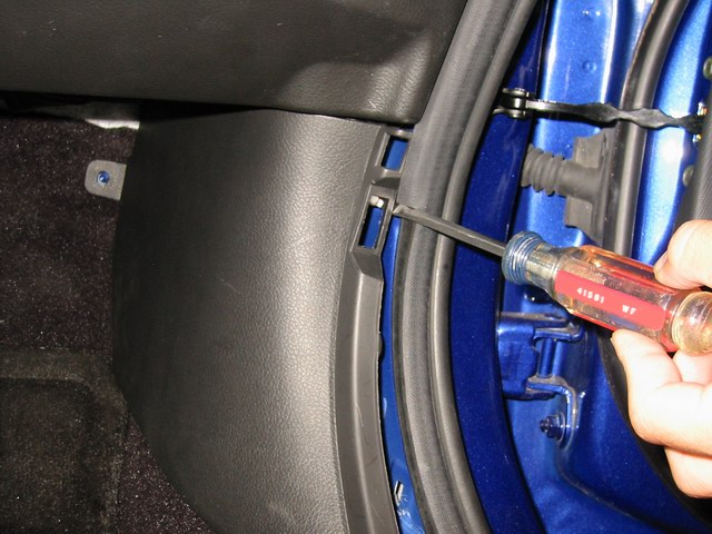
Use the flat head screw driver (if need) and pry the front edge of theside kick panel outwards (towards the driver side) and remove the panel. Be careful of where you put the screwdriver. It CAN break the plastic.
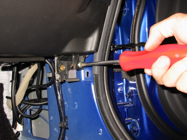
Locate the screw under the kick panel. Use the philips (cross) screwdriver to remove it. You DO NOT need to remove the 10 mm nut.
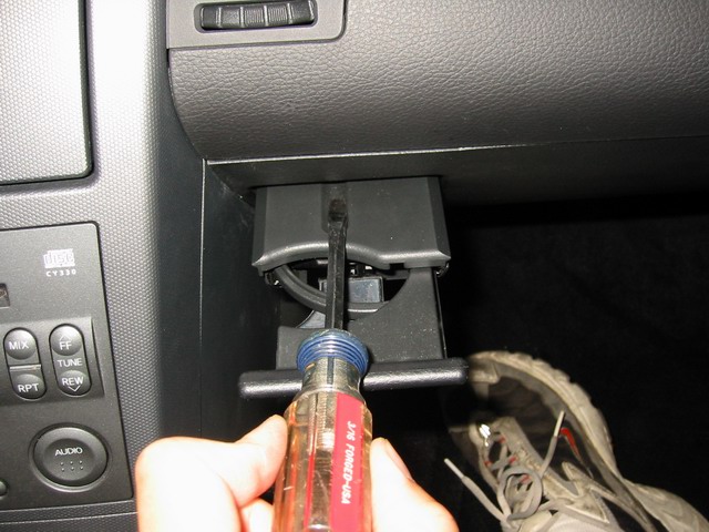
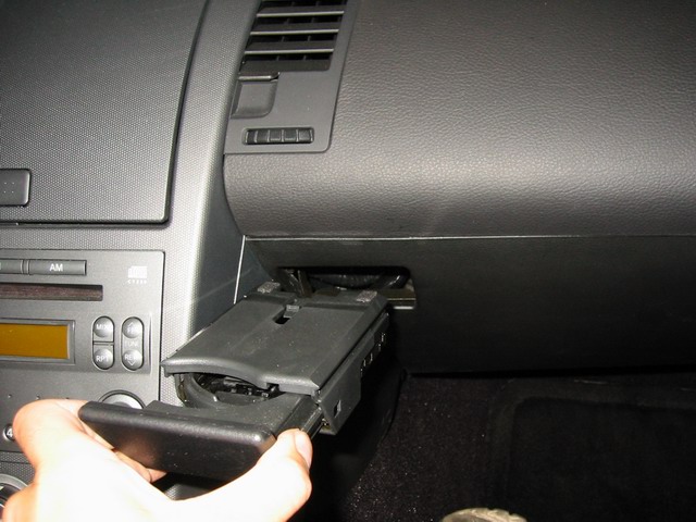
Now pull out the cup holder in the dash area and insert the flat screw driver into it. Gently pry downward on the inner clip and pull out the cup holder. The clip is extremely hard to see, trust me it’s there. (See pictures below.)
Hidden behind the cup holder is a 10 mm bolt. Remove it with the10mm socket and ratchet.
Start from the bottom right corner and pull out the sub-dash panel. It is held on by several clips. Work your way counter-clockwise until all clips are pulled out of their holders. The panel drops down and pulls out.
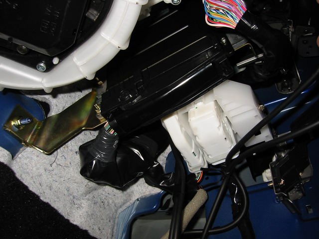
Look up underneath the dash and you will now see the 350Z’s ECU (Engine Control Unit).
To disconnect the harness from the ECU,simply squeeze the tab together (at the end of the connector) and gently pull it down and over. The connector will unhook itself. Pull the connector down and leave it hanging.
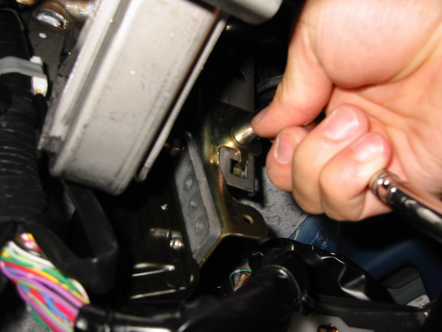
There are now 2 more nuts remaining until the ECU comes out. Look up towards the ECU and you will see a 10mm nut and another one towards the firewall. Remove them and put the nuts in the tray behind the shifter. (Pictures below)
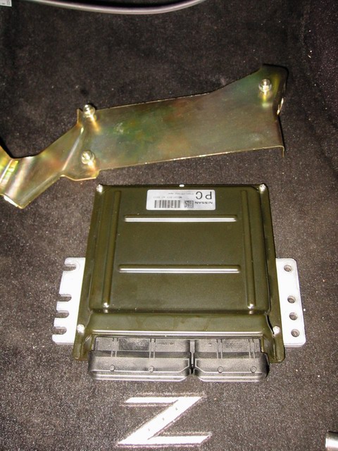
The ECU should come down easily with the bracket. Remove the bracket from the ECU and put all the nuts back onto the bracket. The ECU is now ready to be sent in for Flash Programming.
These are all the parts you should have left over for the removal of the ECU.
Installation is in the reverse order. After the ECU and all panels are installed. There is no need to reset the ECU.
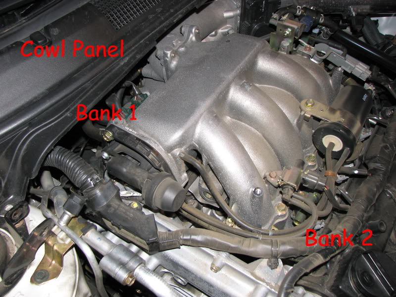
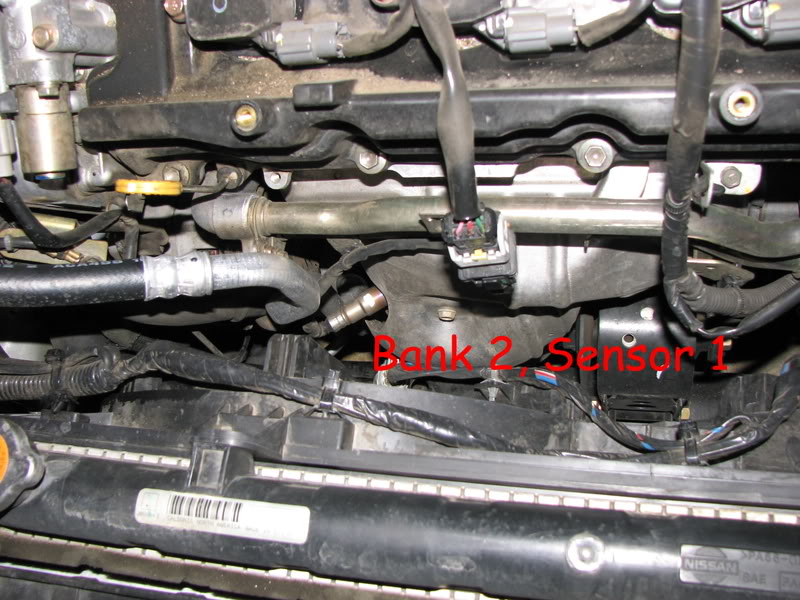
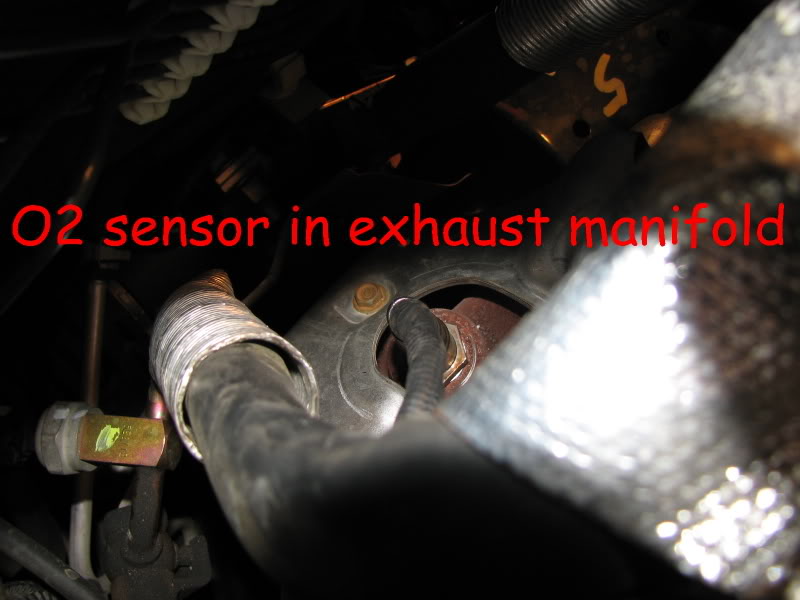
My SES light came on the other day and the code is indicating O2 sensor Bank 1, Sensor 1. That is the bank that is on the back side of the engine, against the firewall. Sensor 1 is the sensor in the exhaust manifold before the cat.
BTW… I priced this sensor at the various auto parts dealers and found the following:
Obviously I was looking for the exact replacement and not a universal fit that I was going to have to splice wires on. Autozone, Advance and Napa all listed the exact same Bosch part number (17264) but their prices varied by nearly $100!
I ordered mine from Napa but after a week they said they were out of stock and so was the manufacturer (Bosch). Advance Auto and Autozone both gave me the same information. Sadly, I had to break down and purchase the sensor from the stealership.
My SES light came on and the code indicated Bank 1, Sensor 1. Bank 1 is the side of the engine closest to the firewall. Bank 2 is on the front, closest to the radiator.
Sensor 1 is in the exhaust manifold, before the cat. Sensor 2 would be after the cat.
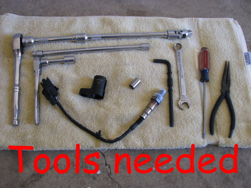
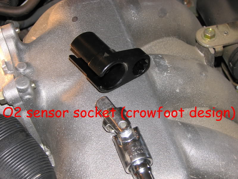
To do the job, you will need a few simple hand tools including a ratchet with extensions, 10mm, 12mm and 14mm sockets, a standard screwdriver, needlenose pliers, and an O2 sensor socket. I used a crowsfoot design O2 sensor socket because a straight O2 socket was not deep enough. If you have a strut tower bar like I have, you will need an allen wrench and 14mm wrench to remove that.
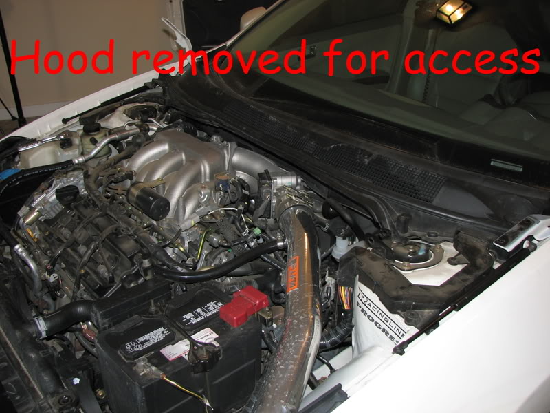
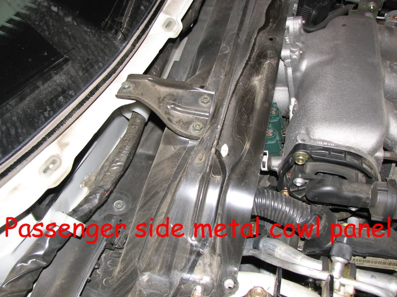
Again, as I stated, my bad sensor was in the bank 1 exhaust manifold. In order to gain access, I had to remove the hood, strut tower bar, windshield wiper arms, plastic cowl panel and metal cowl panel.
When removing the hood, have someone assist you in lifting it off. It is a good idea to mark your hinges with a paint pen so you can align the hood properly when reinstalling it.
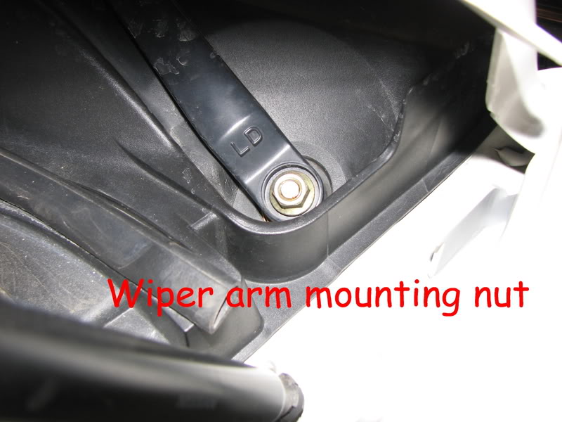
After removing the hood, pull the plastic caps from the wiper arm mounts. Underneath, there will be a nut you need to remove. After removing the nut, the arms will not just slip off. I used a small crowbar to pull up on the wiper arm while I tapped the bolt with a hammer.
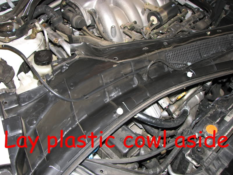
The plastic cowl panel is held in place with 4 plastic fasteners that just push in place. To remove them, I pried up the edge with a screwdriver and used a pair of needlenose pliers to pull them out. Do this carefully or you may break the fasteners off.
Once you get the 4 fasteners out, lift gently on the plastic cowl panel. There are several white clips underneath that will pop out if you lift carefully. After you get it loose, you can lay it on the front of the engine. There is no need to disconnect the windshield washer lines.
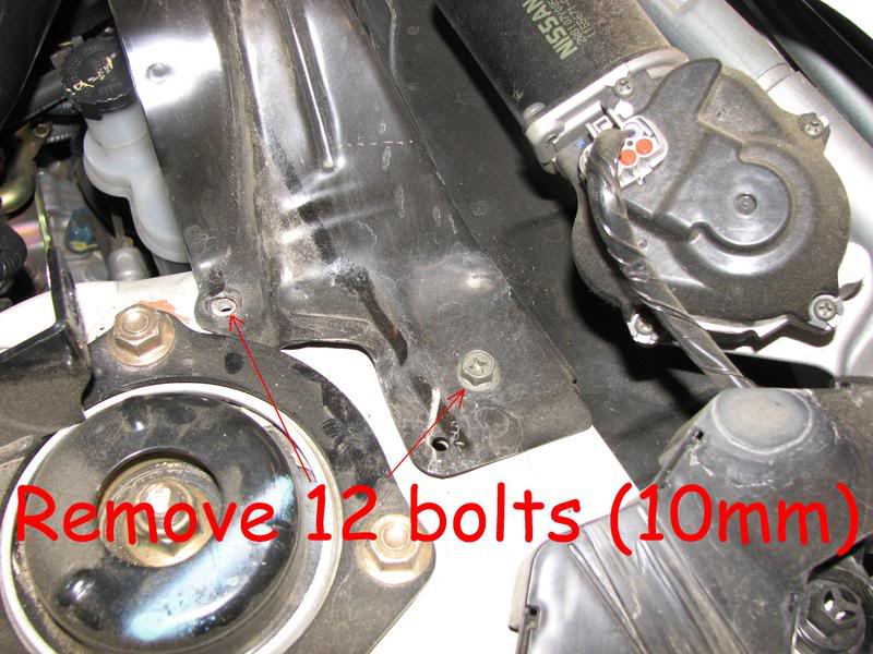
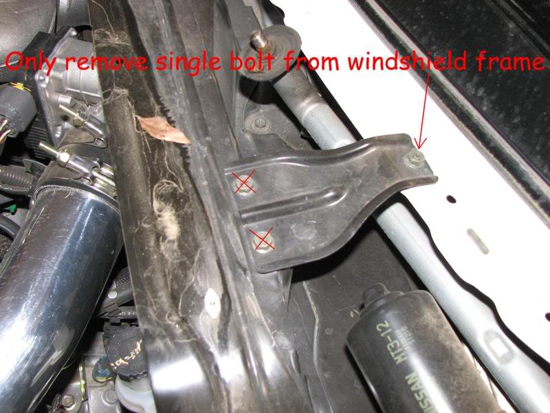
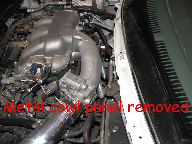
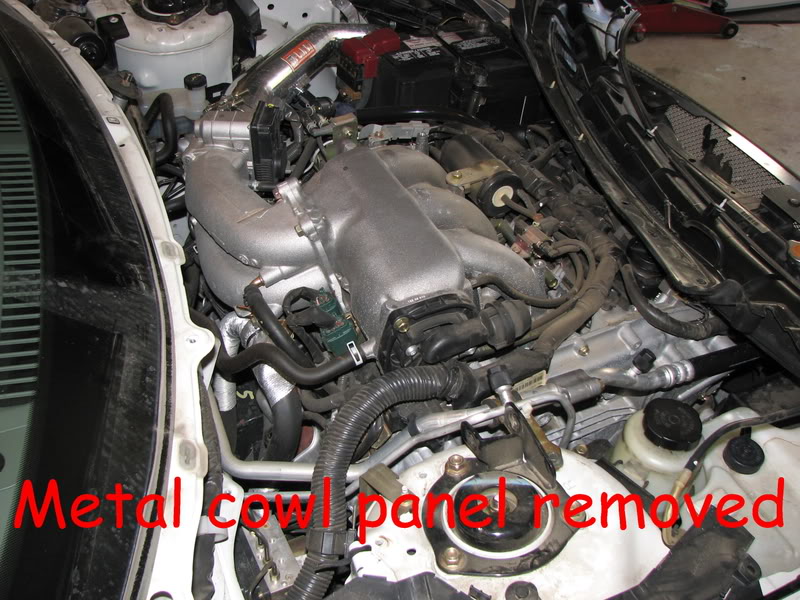
Under the plastic cowl panel there is a metal cowl panel that is held in place by twelve, 10mm bolts. Remove the bolts and lift out the panel.
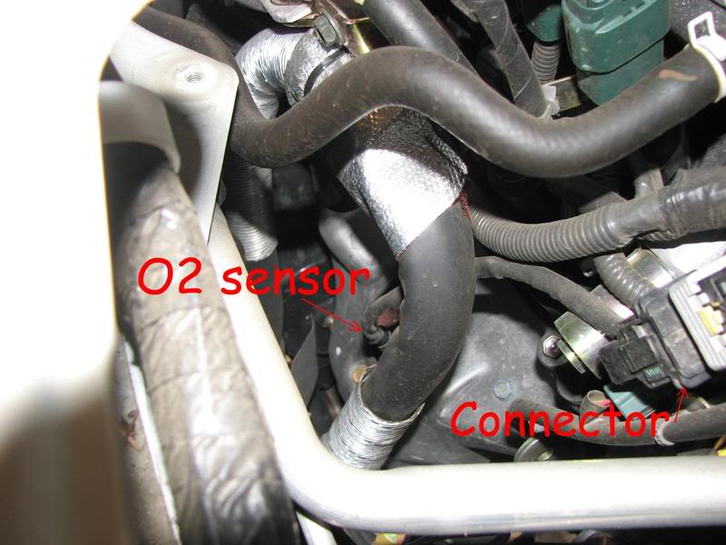
After the metal cowl panel is removed, you will have access to the O2 sensor.
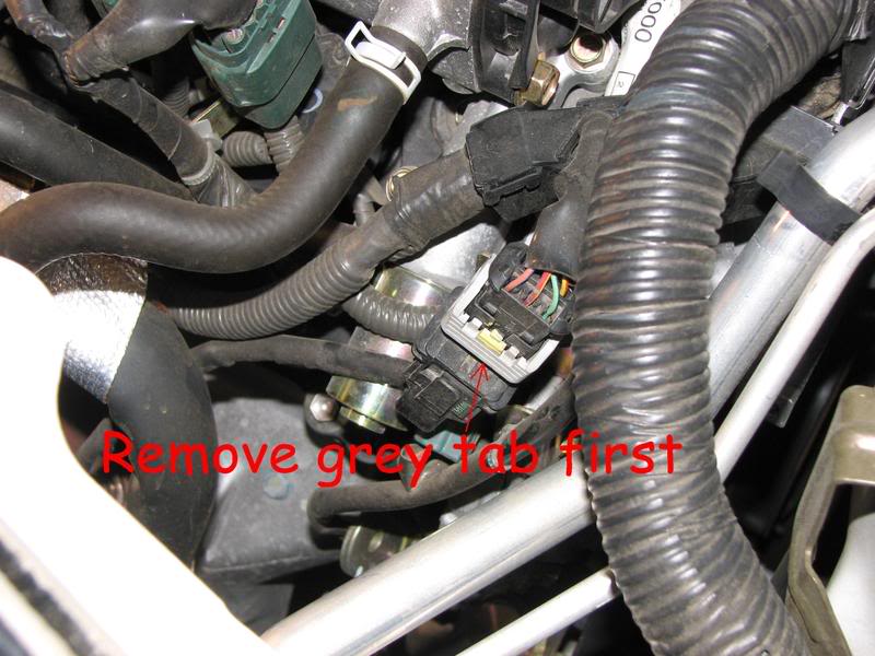
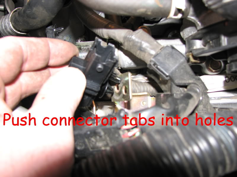
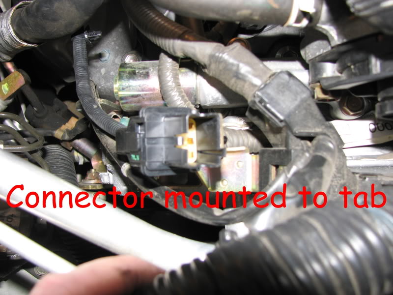
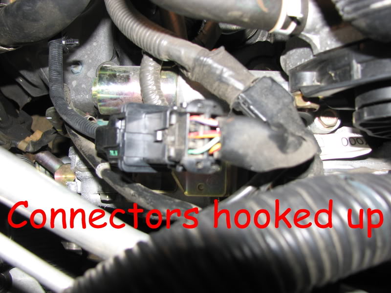
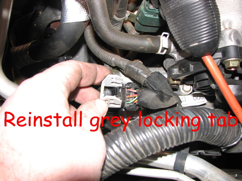
Disconnect the connector first. To do this, you will need to remove the grey locking tab, then pull the connector apart. The portion that is attached to the sensor lead is stuck on a mounting tab.
After you have disconnected the wire, use an O2 socket to remove the sensor from the exhaust manifold.
When you have removed the old sensor, reverse the process for installation.
Important notes:
1. If your new O2 sensor did not come with anti-seize on the threads, put some on. Otherwise, you will never get it out later.
2. DO NOT DROP THE NEW SENSOR! If you do, you will damage it and you will have to replace it.
3. To clear the SES light, disconnect the battery for 20-30 minutes to reset the ECU. Or, you can take it to Autozone or some other parts dealer and they will clear it for you.
4. For all you flamers that want to tell me that my engine compartment is dirty, don’t worry, I detailed it when I was done.
I hope this helps. If nothing else, you can see that you can do this yourself without having to pay the dealer $85.00 per hour to do the job for you.



 Preparation:
 Location:




 Pic 2