Tag

Engine, Trans, F/I & Tuning

Browsing

Member Credit: shift_ice

According to Nissan the 5th Gen Maxima has a “lifetime” filter that never needs changed. In my opinion there is no such thing as a lifetime filter, so I changed mine recently. Many on maxima.org agree that a change is a good idea, and the general consensus is around 50-60k miles.

Here’s proof there’s no such thing as a lifetime filter. This is gasoline I poured out of the filter before trashing it. As you can see, there is a large amount of particles.
Maxima fuse box

I also cut open the used filter and found many surprisingly large pieces of metal embedded in the filter!
Maxima fuse box

I originally thought this process looked intimidating but it’s actually a pretty easy job that shouldn’t take more than an hour, and more likely closer to 30 minutes if you read this how-to first.

NOTE: This how-to is for the ’02-’03, but the process is nearly identical for the ’01-’02. The biggest difference is the assembly has a different part number and looks a bit different on the ’01-’02. Sprillis put together a great how-to for the ’01-’02.

Tools/Supplies:

  • Old towels to soak up gas
  • 10mm socket & socket wrench or phillips screwdriver
  • 8mm socket or phillips screwdriver
  • Needle Nose pliers
  • Small flat head
  • Large pan or bowl (optional, to keep fuel from spilling on counter)
  • 4 large nails

INSTRUCTIONS:

1. Remove the fuel pump fuse in fuse box under steering wheel. It’s the blue 15amp fuse 4th from the right on the bottom row.

Maxima fuse box


2. Attempt to start the car to release fuel pressure. If it starts, let it run until it dies. Then try starting the car two more times letting it crank for a few seconds. This will release the pressure in the fuel lines. Also remove the fuel cap. This helps vent the tank.

3. Remove the back seat by pulling toward the front of the car on two clips that are under the front of the back seat. They are visible in the pic below.

Maxima back seat removed


4. Remove 3 nuts using 10mm socket or phillips screwdriver. After removing the metal cover, release the clip on the wide gray plug so the cover can be set aside.


5. Remove fuel line by squeezing on the blue clips with needle nose pliers and slowly pulling the hose away from the housing. Keep towel handy to soak up any fuel that leaks out. Be forewarned that some fuel may squirt out when the hose is removed since there may still be some pressure in the line.

Fuel hose removed:

6. Remove 6 screws with 8mm socket or screwdriver.

7. Remove the fuel filter assembly by pulling straight up at first and then tilting sideways. Note the floater arm assembly hanging off the passenger side of the assembly. You’ll need to tilt the assembly toward the passenger side once the unit is about halfway out of the tank so the floater arm assembly can be navigated out of the tank.

Remove the assembly from the car and sit it on a few old towels to soak up any fuel that leaks out. You might consider sitting the whole assembly in a large pan or bowl for the next few steps since a lot of fuel will leak out.


8. Before starting this step, I recommend pouring all the fuel you can out of the filter into a container by turning it upside down. You’ll need to turn it right side up and let it sit for a few seconds, then turn it over. Repeat this process until fuel stop flowing out. This will greatly cut down on the mess.

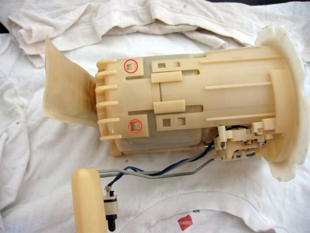
Use a small flathead screwdriver or 4 nails to release the tabs in red. These are on both sides of the assembly so only two are circled in the first photo. Insert the screwdriver as shown in photo 2 and lightly twist until the tab is released. It’s tricky to get all 4 released at once so I recommend using nails under each tab to assure they remain disengaged. Be gentle to assure you don’t break a tab.

Maxima Fuel Filter assembly

I recommend using 4 nails to release the tabs. Just press the nail in toward the top of the tab until it lifts the tab up enough to release it. This is the easist way to release all 4 tabs at once since they tend to slide back on without something wedged behind them.

Using nails to release tabs on fuel filter


9. After releasing all 4 tabs, pull down slowly until the bottom of the unit separates from the assembly. Be careful not to pull too hard because you will need to disconnect a single plug that connects the two pieces.

The two pieces separated:

10. Using the same technique as above, remove the other 4 tabs on the fuel filter assembly.

The two pieces separated:

11. This is what we’ve been hunting for, the fuel filter itself. Remove the gold retainer clip by prying the tabs away and sliding it off the metal post toward the plastic “towers” on the housing.

12. Finally there. Open the new filter and begin reassembly in reverse order using the new filter. When reassembly is complete the car takes a few seconds to start, so don’t be alarmed. You may also notice some stumbling for the first minute or two. Pressure just needs to be regained in the gas line.

Some have reported improved throttle response after changing the fuel filter and many have found the filter to be very black after as little as 30k miles. I found my car now idles smoother and (though this my be in my head) the engine seems to run smoother overall. Assuming my mind isn’t playing tricks on me, I would attribute this to improved fuel flow through the new filter.


13. Install new seal. This seal must be replaced each time the filter is changed. Reinstall filter.

Some have reported improved throttle response after changing the fuel filter and many have found the filter to be very black after as little as 30k miles. I found my car now idles smoother and (though this my be in my head) the engine seems to run smoother overall. Assuming my mind isn’t playing tricks on me, I would attribute this to improved fuel flow through the new filter.

Loading

Member Credit: Unklejoe

I’ve decided to make a quick guide detailing how I installed Mustang Cobra 39# Injectors in my 2002 Maxima.

There was very little information on this topic, other than “it could be done”.

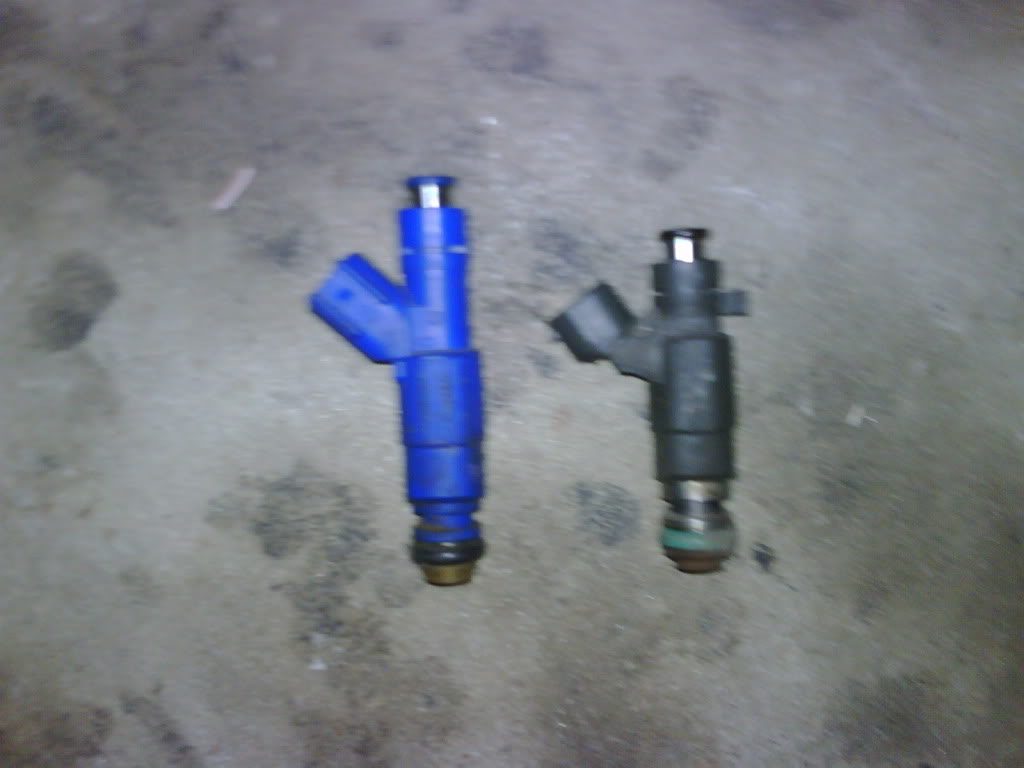
These injectors are rated at 39# at 39 psi, so this equates to roughly 470cc/min when used in the 2002+ Maxima’s 51psi fuel system.

You can find these injectors for around $100 if you look on the SVT forums. This is FAR cheaper than buying the RC 440’s or another similar aftermarket injector. And because these are for the 2003/2004 Mustang Cobra, you will get 8 injectors, leaving you with two spares.

These injectors use an EV6/USCAR connector.

This is the best route for someone who is going to boost or run a large dry shot of nitrous, and doesn’t want to spend a ton of money on new injectors.

PARTS REQUIRED:

(4) M8-1.25 x 40mm Allen Key Screws
(3) FEL-PRO Part # ES70599 (O-Rings, Set of 4) (Got these from Rockauto)
(6) EV6/USCAR Injector Pigtails
(6) 2003/2004 Mustang Cobra “Blue Giant” 39# Fuel Injectors
(20) 5/8″ Washers

PROCESS:

1. Start the car. While the car is running, pull the fuse for the fuel pump (located inside the car; under the steering wheel). The car will eventually stall out. Try to start the car a couple times. This allows the pressure in the fuel rail to be relieved.

2. Remove the upper intake manifold, exposing the lower intake manifold and the rear fuel rail. Place paper towels in the holes of the lower intake manifold to prevent debris from falling in there.

3. Remove the bolts holding in the fuel rails.

4. Rock the fuel rails back and forth (towards the windshield and the front of the car) while pulling up. Eventually the injectors should pop out. They are only held in by the fuel rail. If you can’t get them out this way, remove the clips holding the injectors in the fuel rail, and remove the fuel rails. This will leave the injectors suck in the manifold, but you can then use pliers to yank them out.

5. Grab one of the new injectors and two O-rings. Gently lube the O-Rings with motor oil and slip them on to the new injector. One goes on the top and one goes on the bottom. (DUH)

6. Pop the injector into the fuel rail, then slide the clip over it in the same fashion that it popped off. Repeat this for the 5 remaining injectors.

7. Maneuver the fuel rail back into its position on the LIM.

8. These injectors are about a half inch taller than the stock ones, so the washers must be used to shim the fuel rail up. Use 5 washers per bolt. This also forces us to use allen key bolts, because you won’t be able to get a wrench or a socket in there once the rail is shimmed up, as it would interfere with the top of the lower intake manifold.

9. Now the tricky part. Line up all of the bolt holes and position the washers, then slide the bolt down the hole. This is tricky because it is hard to hold the washers due to the space constraint. Also, the fuel rail has to be slightly bent into place, as the upward spacing changes the angle between the cylinder banks. It’s nothing big, just requires some force to line up the holes.

10. Cut off all of the stock injector plugs. Prepare the EV6/USCAR plugs. I bought a whole pigtail, so I had to solder mine. Crimp on plugs are available though. Each stock injector plug has a solid red wire. This is the ground. Connect the new plugs in such a way that the GROUND CONNECTS TO THE + SIGN ON THE NEW INJECTOR. I’m not sure why Bosch decided to put a + sign on the injector, but ignore it, trust me. The + sign is located inside the injector plug, on the injector itself.

11. Reinstall everything.

NOTES:

Your car will run perfectly fine in closed loop with these injectors without tuning; you will just have a far negative long term fuel trim. This is confirmed by my wide band readings right after the injectors were installed. I do however, have an E-Manage Ultimate, and this allows me to scale the injectors, for easier tuning.

If you do not have a way to tune for these injectors, you will run extremely rich at WOT. If you are installing these in the first place, you already know this.

The drivability has changed slightly with these injectors. The RPM’s seem to fall faster when the clutch is pressed in, causing me to have to shift “faster”. This is not a problem, it will just take some getting used to. I can only attribute this to the Mustang injectors have a faster response than the stock injectors.

PICTURES:

Picture of the bolts required.
Click the image to open in full size.

Picture showing the length difference between the stock and the Mustang injector.
Click the image to open in full size.

Picture of the lower intake manifold, showing the fuel rails. The injectors are already installed in this picture, and the plugs are soldered, but not taped yet.

Click the image to open in full size.

Picture of one of the injectors. This also shows the washers that were used to shim the fuel rail up.

Click the image to open in full size.

Picture showing the fit of the new injectors.

Click the image to open in full size.

Loading

Member Credit: Freeengineinfo

Idle Air Control Valve Replacement

Click the image to open in full size.
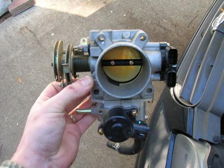
Does your car idle rough or the speed cycle up and down. You probably have a bad idle air control valve. The only purpose of the idle air control valve is to keep the engine’s idle smooth. The engine’s computer gives the idle air control valve the feedback it needs to hold a constant rpm. The idle will be around 1000 rpm’s when not in gear and around 800 rpm’s in gear. This iac valve is on a Nissan Maxima and is similar to most idle air control valves.

Click the image to open in full size.
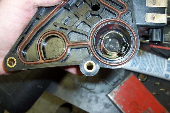
As you can see in this picture there are channels running inside the valve. The iac is a valve with a taper on the end of it that moves in and out to control the air past the throttle into the engine. The air controls the engine speed. This paticular valve also combines a channel for coolant to pass through to help heat the throttle body air. To remove the throttle body you will first need to remove the airbox screws. The have an arrow pointed at them.

Click the image to open in full size.
Remove the top two cables from the clips on top of the airbox. Then you will need to remove the coupling that fits between the airbox and the throttle body. The two clamps shown here will need to be loosened.

Click the image to open in full size.
You will need to move around the airbox to remove the coupling. Next you will need to remove four bolts that hold the throttle body on.

Click the image to open in full size.
Once the bolts are removed there are three electrical plugs that will need to be removed. One is located underneath and is difficult to get at and the other two are on the left side. As you can see in this picture, the green tab will need to be pushed in and up to release the plug.

Click the image to open in full size.
Rotate the throttle body to the right and rotate the throttle until there is enough slack in the cable to slide it out of the hole. Both will need to be removed. Then there are two hoses that will need to be removed, then you can finally remove the throttle body. Look on the bottom of the throttle body to see the idle air control valve.

Click the image to open in full size.
To remove the idle air control valve, simply remove the five screws that attach it to the throttle body. If you also left the hose on the iac valve, as is done in this picture, don’t forget to attach it to the new idle air control valve. Then reassemble everything opposite the way you removed it.

Loading

Member Credit: speed racer

These were the tools used:

1. Philip Screw Driver
2. Dremel with cutting accessory
3. Needle Nose pliers
4. Hair Tweezers
5. 10mm socket

Click the image to open in full size.

In this picture you can see where the two small screws hold the valve plate. You really only have one shot of unscrewing them. I advised that you apply as much pressure on the screw head and turn ever so slightly until you break the seal. I was able to get about 50% of them off and the others just ended up being cut off b/c the screw head got stripped.

There also two screws on each side of the valves openings that need to be removed.

Click the image to open in full size.

In this picture you can see how the plate is off and what is left is just the rod stick.

Click the image to open in full size.

I used the Hair Tweezers to remove the e-clips on the rods. There are three in total. You will see that there is enough space for you to grab the eclip with the tweezers. Once you have a firm grip just pull and they should easily come right off. After this is done its as simply as unhooking the rods from the Valve Solenoid assemble.

Don’t forget to remove the two 10mm bolts on the Valve Solenoid bracket.

Loading

This applies to 2002-2003 5thgens.
Member Credit: maxima dude

Before attempting any of the following procedures, it is advisable that you read through the instructions thoroughly and familiarize yourself with them. A stop watch or an analog clock with a second’s needle will be useful. ( i counted outloud becuz i didnt have a stopwatch lol)

ECU Resetting Procedures
Timing is extremely critical. If it is NOT DONE within the specify time, the ECU will not reset and the Check Engine Light (CEL) will continue to remain ON.

Operations Procedures

1. Confirm that accelerator pedal is fully released, turn ignition switch “ON” and wait 3 seconds.
2. Repeat the following steps (2a and 2b) procedures quickly five times within 5 seconds.
2a. Fully depress the accelerator pedal (HARD).
2b. Fully release the accelerator pedal.
3. Wait 7 seconds, fully depress the accelerator pedal and keep it for approx. 10 seconds until the CEL starts blinking.
4. Fully release the accelerator pedal (while the CEL is still blinking)
5. Wait about 10 second.
6. Fully depress the accelerator pedal and keep it for more than 10 seconds.
7. Fully release the accelerator pedal (The CEL light will continue to blink).
8. Turn ignition switch to “OFF” position and now you can start the car. The CEL light should be gone.
If the CEL light continues to remain ON, repeat the above steps. Timing is EXTREMELY critical to resetting the ECU.

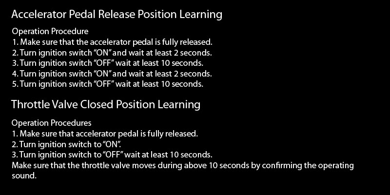
Accelerator Pedal Release Position Learning

Operation Procedure

1. Make sure that the accelerator pedal is fully released.
2. Turn ignition switch “ON” and wait at least 2 seconds.
3. Turn ignition switch “OFF” wait at least 10 seconds.
4. Turn ignition switch “ON” and wait at least 2 seconds.
5. Turn ignition switch “OFF” wait at least 10 seconds.

Throttle Valve Closed Position Learning

Operation Procedures

1. Make sure that accelerator pedal is fully released.
2. Turn ignition switch to “ON”.
3. Turn ignition switch to “OFF” wait at least 10 seconds.
Make sure that the throttle valve moves during above 10 seconds by confirming the operating sound.

Idle Air Volume Learning (Throttle Position Learning)

It is better to count the time accurately with a clock. 1. Perform “Accelerator Pedal Released Position Learning”.
2. Perform “Throttle Valve Closed Position Learning”.
3. Start engine and warm it up to normal operating temperature.
4. Turn ignition switch “OFF” and wait at least 10 seconds.
5. Confirm that the accelerator pedal is fully released, then turn ignition switch “ON” and wait 3 seconds.
6. Repeat the following (steps 7a, 7b) procedures quickly five times within 5 seconds.
7a. Fully depress the accelerator pedal (HARD)
7b. Fully release the accelerator pedal.
8. Wait 7 seconds, fully depress the accelerator pedal and keep it for approx. 20 seconds until the Check Engine Light (CEL) stops blinking and turned ON.
9. Fully release the accelerator pedal within 3 seconds after the CEL is ON.
10. Start engine and let it idle.
11. Wait 20 seconds.
12. Rev up the engine two or three times and make sure the idle speed and ignition timing are within the specifications.

IMPORTANT

***** when you have the idle at the factory settings… shut off the car and disconnect the negative battery terminal as soon as you shut the car off also turn on the headlights after to get any additional juice out.( i waited about 10-15 minutes)..keep it unplugged for a couple of minutes and then connect it all back together and this should save your factory idle….many 02-03 maximas have trouble keeping the idle learned in the computer…resulting in the same high idle as what you started with….when you start the car again….this took me about 4 tries to get it right…might take you more then once..so be patient and keep trying. Good luck!

Loading

This applies to 2000-2001 5thgens.

VIAS stands for Variable Intake Air System. It is made up of a power rod going through your intake manifold that holds a series of butterfly valves. A solenoid turns the rod at 5000 rpm to open the valves to allow the engine to breathe better. Nissan VIAS video link.

The VIAS system is 100% of the reason 5th gen maximas have higher horsepower than 4th gen. All the 4th gen guys lust after VIAS intakes and buy them when they can.

However, the VIAS has a design problem – an extremely weak connection in the internal linkage that is destined to fail in 100% of 5th generation Maximas. You lose about 30 horsepower at the top end as a result. I didn’t know what I was missing until I got those ponies back!

The good news is that it is very easy to fix – about 20 minutes of wrenching plus waiting for the JB weld to set. $5 for 30 HP – good deal! I took mine apart and fixed no problem. Here’s how:

This is the VIAS solenoid unit. It is on the drivers’ side of the intake manifold. Even if the solenoid works properly when you hit 5000 RPM, your internal linkage is still either broken or soon will be. The solenoid mechanism is held on with four very soft yet quite stuck screws. One of the screws is blocked by the throttle body.

Click the image to open in full size.

This is the screw blocked by the throttle body. Some people are able to rotate the throttle linkage to get at it, but I simply loosened throttle body. It is NOT necessary to remove throttle body completely, nor remove any of the hoses attached to it.
Click the image to open in full size.

Hidden screw again. Be sure to use #3 Phillips or big slotted screwdriver on these screws. They are very soft and heads strip easily. You can also use impact type screwdriver or proper bit in drill. If stripped, can still be removed with vise grips.
Click the image to open in full size.

Cup should be attached here: but it is broken off due to crappy design. Some owners find their cup is still attached, but loose. The cup should NOT be able to rotate independently of shaft. See how dirty mine is? Clean the whole area shown with brake cleaner as well as inside and outside of cup.
Click the image to open in full size.

Now it’s so clean it shines. Put a little JB Weld or JB Kwik on bottom of cup where it mates with solenoid shaft, then a good coating on inside bottom of cup. Try to keep sides cleaner than I did! Pay attention to cup “handle” orientation. You decide. Make sure everything rotates freely when you push lever on solenoid.
Click the image to open in full size.

Pressing the spring in while JB is tacky prevents a clearance issue with end of rod. Otherwise your pool of JB Weld may make cup too shallow for spring and rod. Doing this, you don’t need to cut spring. Also, if you want to play with removing power rod later, you don’t need to disassemble solenoid end. Let JB get good and hard before re-assembly. With Kwik, I’d wait at least 2 hours; regular JB should be left overnight at least.
Click the image to open in full size.

Reassemble and feel the power!

Mr. Blue Sky Note: If you want to take your Power Rod out and Put a Blockoff Plate on(either bought through the big org, or made yourself, then you may have to remove the UIM. You could try doing it with just the VIAS holder off, but I am not sure if it is possible

Power Rod Removal (broken VIAS situation)Courtesy of BlackBIRDVQ on maxima.org
Power valve can be removed without pulling the intake manifold off. I’ve done it on my Maxima after my cup has completly came apart beyond any JB Weld fix.

You will wanna remove the VIAS box, remove the cup and spring. Then move over to the passenger side of the engine and you will notice a SILVER end cap that will be on the side of the plastic intake manifold- its held on by 2 screws. Gently pry the vacuum lines etc out of the way and remove this silver cap off the intake manifold. After that you MIGHT have to move the power steering reservoir out of the way- as I think it might hit the power valve when U try to remove it out of the intake. After you get it out, put the VIAS box back up, make sure nothing is left inside it or it will get sucked into the motor, put the silver end cap back on also.

Be advised that the LOW end and midrange power will suck, it will feel very sluggish till bout 5K RPM. At that point the engine becomes a monster and pulls like MAD till fuel cut. Based on conversations with SR20DEN and others who tried the power rod removal, they came up with conclusive results- power doesnt drop off till you hit the fuel cut. There are some substantial top end gains to be had with the removal of the power rod, but at the expensse of the low to mid range power.

Try it out, if you dont like it you can always put the rod back in and have the lousy top end back. In the mean time I will try to talk to some Nissan reps/engineers bout a possible avalibility of repleacement VIAS box, so that in case it breaks we can repleace it with a good one and not have to remove the whole intake to fix it. A redesign should really be done, but I am not sure if that would be possible.

Loading

Member Credit: Froggmann

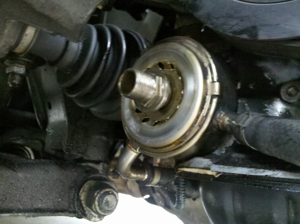
Backing out of your driveway you notice a good sized-oil spot from the passenger side of your car. You get out to investigate. It’s engine oil and seems to be a lot of it. You go start investigating, oil pan looks ok. Front oil seal looks ok, then you spot it it’s coming from behind the thing the oil filter is connected to. You have just discovered the reason behind Nissan Service Bulletin NTB06-02:

Why would you want to eliminate it? In cooler environments, I wouldn’t. Here in So Cal it doesn’t get cool enough to necessitate it. Not to mention I don’t see how having 200* F coolant going around the base of the oil filter actually cools anything.

So lets start with the repair…

Step 1 – Drain the oil out of your engine. You will need a 14MM socket.

Step 2 – Remove the oil filter. You will need an oil filter wrench or channel-lock pliers.

Click the image to open in full size.

Step 3 – You will need to remove the Center bolt using a 22MM or 7/8″ deep socket. After that the cooler/warmer will fall forward. Remove the two 12MM bolts holding the forward coolant line to the block. This will give you enough wiggle room to get the old O-ring off and the new one on.

Click the image to open in full size.

If you are going to remove the cooler/warmer completely skip to the next post.

Step 4 – Remove the old O-ring, then clean the inner channel with a rag then insert the new O-ring.

Click the image to open in full size.

Step 5 – Re-attach the cooler to the block ensuring the clocking notch is correct.

Click the image to open in full size.

Tighten the center bolt to 33-39 Ft pounds of torque. Then continue with your normal oil change steps.

To remove the Cooler/Warmer completely first attain these things:

12MM Allen socket or wrench.
Oil filter nipple from a 3.0L VQ. If you don’t have any junkyards nearby you can just order it, it’s Nissan part number 15213-31U00.

About 1.5 feet of 1/2″ (13MM) heater hose. Alternately, you could take your water pipes in to a welder to have the nipples removed but that’s not my cup of tea.

Starting off from here:

Click the image to open in full size.

Get your VQ30 oil filter nipple:

Click the image to open in full size.

and attach it to the engine block. Tighten it to 33-39 Ft Lbs. of torque. At this point you can install your new oil filter.

Click the image to open in full size.

At this point if you are due for a coolant flush, drain your coolant. If not we can work around that.

Remove the coolant line going towards the front of the car first, then pinch the hose over on itself and hold it in place with a pair of vice grips. Coolant will be pouring out so do this quickly.

Attach your 1/2″ rubber hose to the hardline and secure with a hose clamp.

Grab your other hose clamp and put it over the hose. You will thank me later for this.

Detach the rear coolant line and attach your 1/2″ hose and secure with the hose clamp. Again do this quickly if you are not flushing your coolant.

Re-attach the 2 bolts holding the front coolant line and torque then to 33-39 Ft. Lbs of torque.

Continue with your oil change and top off your coolant. Idle your car and look for leaks, if none are found go and relax with your beverage of choice:

Click the image to open in full size.

Loading

This applies to the 2000-2001 5thgens.

Before performing Idle Air Volume Learning, make sure that all of the following conditions are satisfied. Learning will be cancelled if any of the following conditions are missed for even a moment.

Battery voltage: More than 12.9V (At idle)
Engine coolant temperature: 70 – 100 C (158 – 212 F)
Park/neutral position (PNP) switch: ON (Shifter in Park or Neutral)
Electric load switch: OFF (Air conditioner, headlamp, rear window defogger)
Steering wheel: Neutral (Straight-ahead position)
Vehicle speed: Stopped
Transmission: Warmed-up (Drive vehicle for 10 minutes.)

Procedure:

1 Turn ignition switch “ON” and wait at least 1 second.

2 Turn ignition switch “OFF” and wait at least 10 seconds.

3 Start engine and warm it up to normal operating temperature.

4 Check that all items listed under the topic PREPARATION (previously mentioned) are in good order.

5 Turn ignition switch “OFF” and wait at least 10 seconds.

6 Start the engine and let it idle for at least 30 seconds.

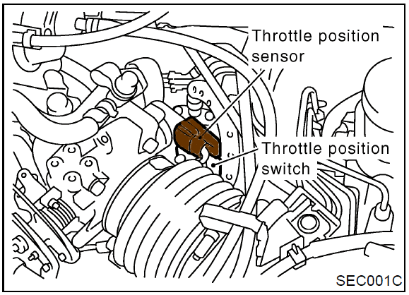
7 Disconnect throttle position sensor harness connector (brown), then reconnect it within 5 seconds.
Click the image to open in full size.

8 Wait 20 seconds.

9 Make sure that idle speed is within specifications. If not, the result will be incomplete. In this case, find the cause of the problem by referring to the NOTE below.

10 Rev up the engine two or three times. Make sure that idle speed and ignition timing are within specifications.

Idle speed = 700 ± 50 rpm (in P or N position)

Loading

Member Credit: The Wizard

How to Re-clock your Supercharger
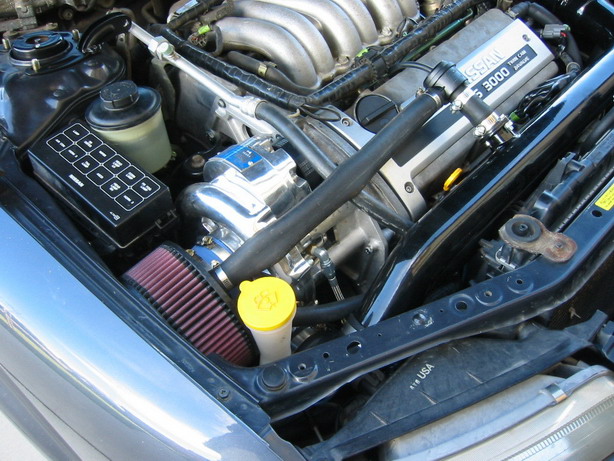
Why? So that one of the bends of the 2.5″ charge pipe can be eliminated (the retarded chamfered elbow) and ease of configuration for those who want to upgrade to a 3″ charge pipe system. Re-clocking the blower also gets the charge pipe away from the back of the headlight and allows a lot more room for those who do headlight retrofits. (My chamfered elbow was rubbing my OEM headlight bulb connection and causing it to flicker on and off)

Keep in mind that if you’re keeping the 2.5″ charge pipe that originally was provided in the Stillen kit, then you’ll have to cut off a portion at the end of the charge pipe (at the second bend near the SC mounting plate) and get a new silicone 90 degree coupler (2.75″ to 2.5″) to reconfigure the system. If you’re upgrading to a 3″ charge pipe, then you’ll have to buy quit a bit more including: piping/couplers/your choice of BOV, Maf adapter etc.

Where? In your car, blower fully installed and mounted to the engine. It’s a common misconception that the blower must be removed from the car in order to re-clock the blower. You do not have to take the blower off the car, unless you run into the problem stated in the disclaimer below. This probably goes without saying, but re-clocking the blower while installed in the car allows you to fine tune and find the perfect angle in such a way that the 90 degree silicone elbow is situated just right and allows proper hood clearance. If the blower was removed from the car, then you’ll be taking the trial and error approach and burning a lot of time taking the blower/plate on and off/re-clocking the blower in order to find the perfect angle.
Here’s how the blower looks as Stillen/Vortech intended (2.5″ charge pipe, two bends at/near blower outlet)

Click the image to open in full size.

Here’s how the blower looks re-clocked (3″ charge pipe, one 90 degree bend)

Click the image to open in full size.

Here’s how to re-clock (rotate) your blower

Pic 1
Click the image to open in full size.

Pic 2
Click the image to open in full size.

Look near the oil feed fitting and you’ll see a hold down plate and two allen screws. (See Pic 2) Keep in mind, there is still one more hold down plate and two screws to locate. See pic 1 for both plates (outlined in red) and all 4 screws (noted in green). Although the blower is installed in the car and space is limited, you should have no problem getting to the plates and allen screws. The hold down plate and screws holds the scroll to the blower itself. Loosen the screws quit a bit until you are able to re-clock (rotate) the blower’s outlet. You can remove the screws and hold down plates if you find it easier or the scroll isn’t rotating freely. Now re-clock the blower’s outlet to the desired position. Tighten the allen screws to prevent any further rotation and snug things back up the way they were. If you removed the 4 allen screws and 2 plates, reinstall them at this time.

* Some people have reported that they have 5 screws and 3 hold down plates. If you can’t re-clock the scroll after undoing/removing the 4 screws and 2 hold down plates as stated above, then look for a fifth screw and small hold down plate. This small hold down plate is only slightly bigger than the screw head itself. This 5th screw and small plate is noted in blue in Picture #1.

Disclaimer: Some people have it easier than others. Some discover that one of the plates is easily accessible (12 o’clock position) while the other is impossible to get to (6 o’clock position) while the blower is installed in the car. If this is the case, you may have to remove/uninstall your blower from your Maxima to gain accessibility to the hidden plate and screws. If so, feel free to relocate the plate and screws to a more accessible location anywhere around the perimeter of the scroll. Just keep in mind, that wherever you install one plate, the other plate should be on the opposite side of the scroll. When I re-clocked my blower, I had it easy. Both of my plates and 4 screws were easily accessible (3 o’clock and 9 o’clock position) [Positions are based on the individual standing at the passenger side of the car and looking at the blower]

Loading

This article explains the various ways of resetting and/or clearing codes on your 6thgens. It should also work for any of the current generation Nissan and Infiniti vehicles. Clearing the codes will turn off any check engine lights (aka: SEL, CEL, SES, etc..). There is a table of OBDII codes at the end of this page to reference. You will need an OBDII scanner in order to pull the error codes. Some high end scanners will tell you both the code and the definition, but many simply tell you the code. If you have a scanner, you can use it to turn off the error codes. If the same code and CEL comes back, you should investigate the problem.

Clearing Codes

There are several ways to clear ECU error codes.
Scan Tool

If using a scan tool, follow tool manufacturer instructions to clear Codes.
Manual Method

Here is a quick way to reset your ECU. It is also known to clear codes thrown, and turn off the “Service Engine Soon” Light. It’s a little tricky, but works.

  1. Confirm that accelerator pedal is fully released, turn ignition switch on and wait 3 seconds.
  2. Repeat the following two procedures quickly five times within 5 seconds:
    1. Fully depress the accelerator pedal (HARD).
    2. Fully release the accelerator pedal.
  3. Wait 7 seconds, fully depress the accelerator pedal and keep it for approx. 10 seconds until the CEL starts blinking.
  4. Fully release the accelerator pedal (while the CEL is still blinking)
  5. Wait about 10 seconds.
  6. Fully depress the accelerator pedal and keep it for more than 10 seconds.
  7. Fully release the accelerator pedal (The CEL light will continue to blink).
  8. Turn ignition switch to On position and now you can start the car. The CEL light should be gone.
Click the image to open in full size.

With Consult

  1. Turn ignition Off.
  2. Connect Consult he data link connector (DLC), located behind fuse box cover.
  3. Turn ignition On.
  4. Touch Start.
  5. Touch Engine.

Perform each diagnostic test mode according to each service procedure.

Without Consult

  1. Turn ignition On.
  2. Turn diagnostic mode selector on ECU fully clockwise and wait until inspection lamps flash. #Number of flashes displayed indicates corresponding mode.
  3. Note number of flashes, then immediately turn diagnostic mode selector fully counterclockwise.
  4. If ignition is turned Off during diagnosis, in each mode, and then turned back on again after power to the ECU has dropped off completely, diagnosis will automatically return to Mode I.
  5. For description of modes, proceed as follows:
    1. (Mode I): with engine stopped, system in bulb check state. with engine running, system in malfunction warning state.
    2. (Mode II): with engine stopped, system in self diagnostic results state. with engine running, system in front O2S monitor state.

Loading