This morning I went to change the serpentine belt on my 1998 4thgen Nissan Maxima. While it’s a simple task, it turned out the “Adjustment Bolt” was also seized and slightly bent. It definitely needed to be replaced. The good news is that you can buy just the “Adjustment Bolt” and/or “Adjustment Nut” by itself. You don’t need to buy the entire assembly. If those are your only two broken parts like me case, then all you need to order (or get at a junkyard) are these two part numbers:
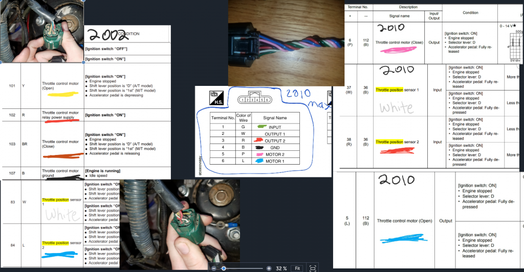
So I am currently in the middle of swapping an HR motor from a 7th gen Maxima into my 5th gen and came across the throttle body harness swap and I couldn’t find anything about it via searching besides buying an adapter online so I thought I’d share how I soldered mine DIY.
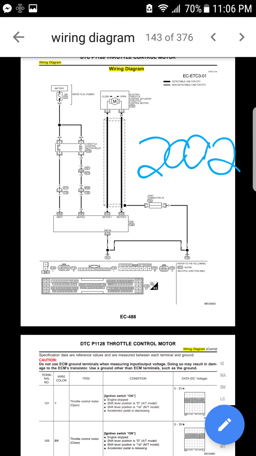
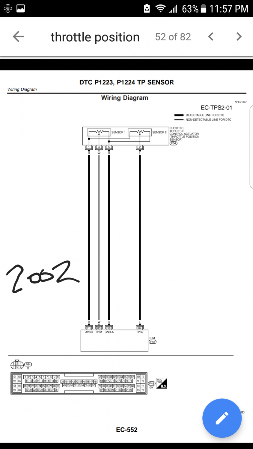
Below are some pictures I attached to show some diagrams, also what each wire from each harness, its color, the year of the car and the wire’s function. (sorry about the weird layout, was using software I wasn’t familiar with)
The first picture on the top left has information for both cars, 2002 on the left, 2010 on the right. the rest are the diagrams to be sure they are connected correctly.
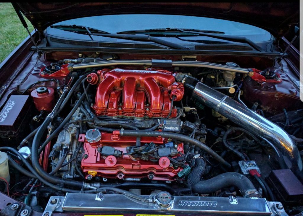
Are you looking for Forced Induction Ideas on your Maxima? Well look no further. This is a gallery of Forced Induction Maxima setups. Setups include Superchargers, Turbos and Nitrous (N20).
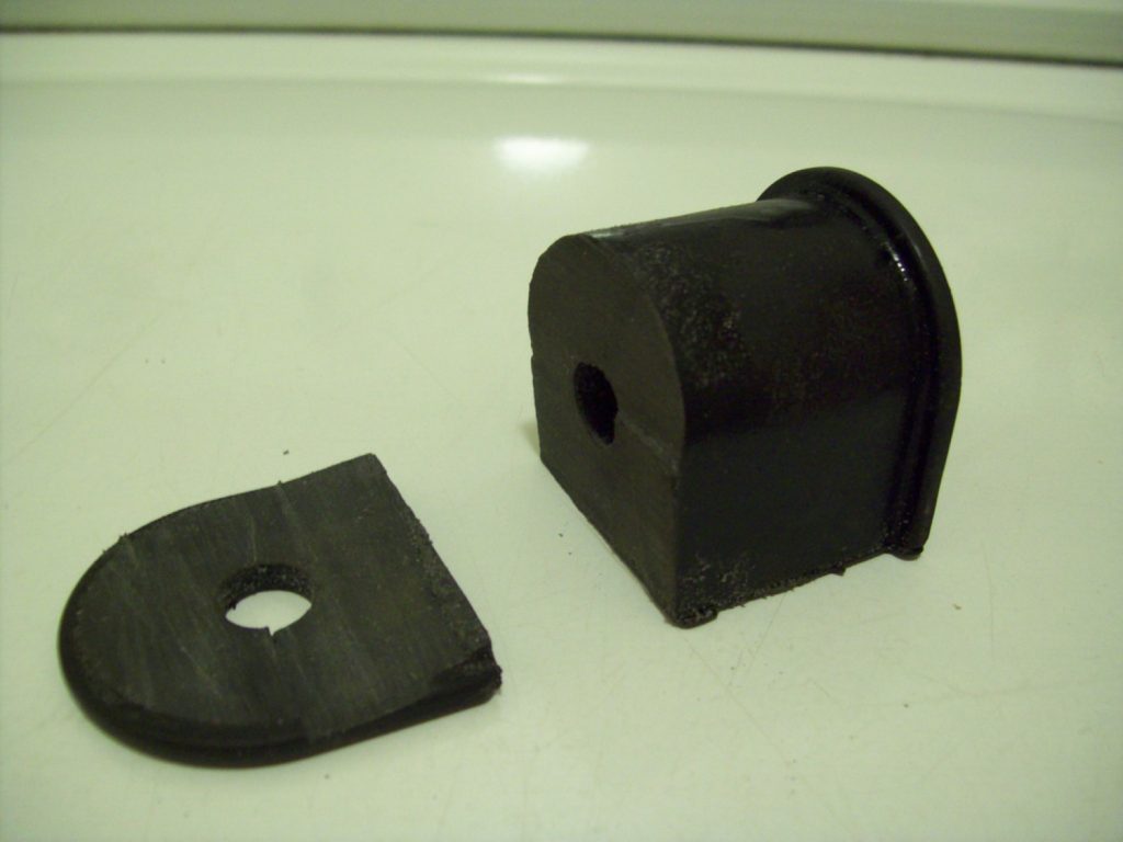
I was thinking about making a solid shifter bushing when I came across this on a Sentra forum. It uses Energy Suspension sway bar bushings. Part # 9.5101
I paid $20 for a set of two. Only downside is that you can’t buy them individually.
The shifts don’t feel as smooth, but they do feel much more solid. I do feel a bit more vibration in the shifter. These impressions are with ES Motor mounts and NWP TQ Link installed. Overall I’m very happy with this mod.
Only one modification is needed. You need to cut off the lip on one side of the bushing, otherwise the support rod won’t fit back in. I also used one of the washers these bushings came with under the bolt on the rear of the shifter bushing.
Some of the pictures suck, I’ll retake some when I get around to it.
Stock bushing vs unmodified ES bushing (I had already installed the modified one)
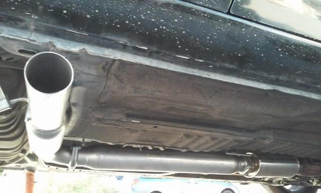
I’ve been mulling over a side exit exhaust off and on the past year. I pulled the trigger on Black Friday as 2J-Racing had their 3″ B15 side exit exhaust on sale. Having only eyeballed pictures of it on their website and those that others have posted, I was anticipating that some modification would be required but should be close enough.
First and foremost, weight reduction. My A32 Cattman 3″ catback w/o2 sensor weighed 39 lbs. The 2JR B15 side exit came in at 23 lbs. Unfortunately, I don’t have a complete stock A32 catback to compare.
The only modifications needed to make it fit is to weld or bolt on a longer piece of steel to the included exhaust hanger, an o2 bung will need to be added. Lastly depending on personal preference, a new flange could be sandwiched between the rearmost joint, or you could take a BFH to the exhaust tunnel. YMMV if you still have the heat shields installed.
As it currently sits (with only the modified exhaust hanger) the exit pipe hangs roughly an inch below the pinch weld. The flange spacer and/or a BFH should allow the exit pipe to be tucked up more.
First impressions on sound, well its definitely louder than the Cattman 3″. At a warm idle and maintaining speed is when its the quietest. Light acceleration reminds me of a super loud honda putting around town. WOT reminds me of a raspy G/Z with test pipes. I’ll report back after I’ve put more miles on it.
I should be recording some video of it with a gopro soon. I have a start up vid, but the phone was too close to do much good.
Member Credit: Shaquille Keon Jenkins & Philly Rillin
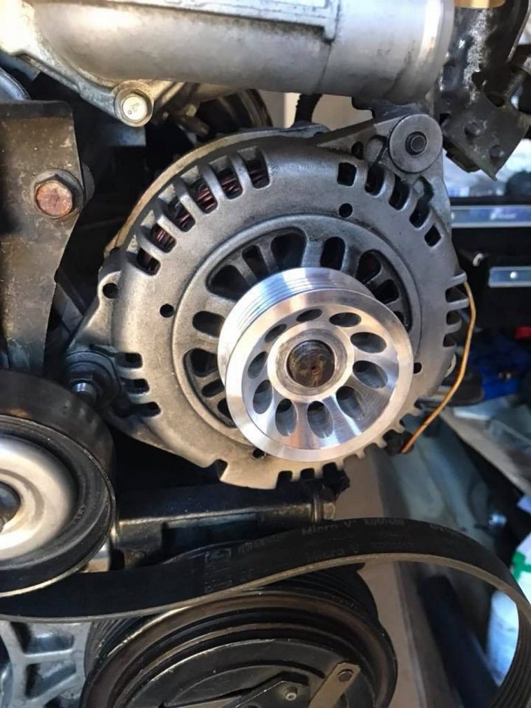
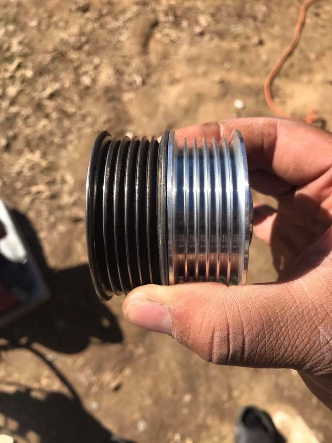
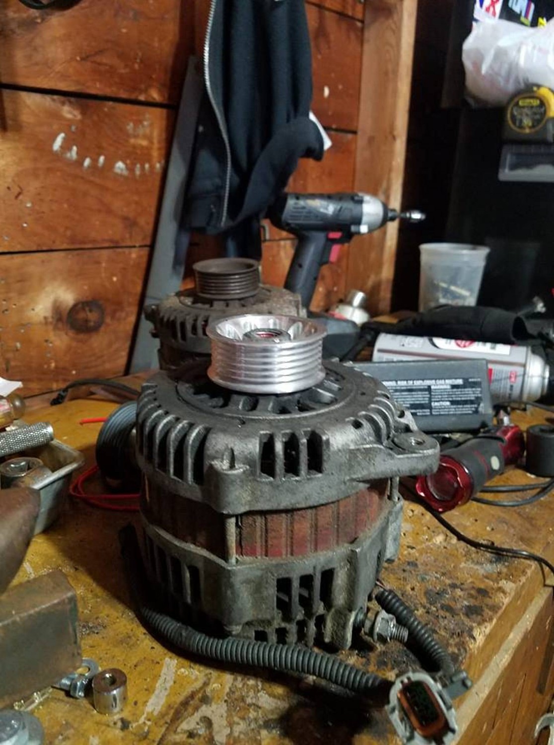
The 350z lightweight alternator pulley fits VQ35 Maxima’s. Same exact size. Its a little thick in the middle so the nut doesnt thread all the way in but with red loctite and an impact gun does the trick. Best part of all, it’s lighter!
I bet over 75% of 4th gen owners have a leaking steering rack and/or worn tie rods. I bought the 99se rack because it is stiffer. It comes with new inner tie rods and new o-rings. You should replace the outer tie rods and sway bar. bushings at the same time.
As for the how to:
Loosen lugs
Jack up and put the car on jack stands.
Remove wheels
Remove outer tie rods(I did not and paid for it ) – You need to rent the outer tie rod removal tool from
AutoZone to do this.
Remove the bolt on top of the sway bar end link and the 2 bolts on the bracket that holds the “inner” bushing in.
Move the sway bar up and wiggle it out from the passenger side.
Remove the ypipe (rent the o2 removal tool) As you can see, I forgot to rent the tool. Now the fun part. Crossmember. Remove the engine mount bolts, in the rear I used a long 10in extension to get to the bolt from the engine bay(intake removed). Front engine mount you need an open end wrench on one side and a socket on the other(or two sockets…) I supported the engine with a jack and a 2×4. If you have a tranny jack it would be better. Remove the 2 bolts in the front and rear(4total bolts) on the cross member and it will drop down. You can replace the mounts right now if you want too.
See a plate covering this mount on the rack. It is behind the rear header and is held on by three 10mm screws. Remove it. Now remove the fluid lines, have something to catch the fluid(I had a trash can lid). Remove these from the engine bay, it is much easier that way. Use a 14mm open end wrech to get the bottom one. On the top one, remove the hose and swap the nipple on the new rack once it is out of the car. Remove those nuts. Now you will see the spindle, there is a 12mm nut holding it on the spindle of the rack. Make sure the steering wheel is strait before you remove it.
Remove the bolts holding on the rack now. One mount is pictured above, other you will see when you are down there.
You will remove the rack from the middle, it will NOT slide out from the sides(I found out the hard way). You will move it towards the pass side and then drop it down in the middle. You will install it the same way. I also installed new bushing on the rack, I got MOOG bushings from rockauto.com
You will soon find out the spindle does not want to go into the joint. You will have to bang on top of the joint to get it on the spindle. I used my tq wrech and breaker bar to bang it in. I didnt have a rubber mallet(I did this with the rack mounts partially in, only the lower nuts were in). Rest is the reversal.
Next you get it aligned… I still have to do this, my wheel is cocked to the right.
This will take all day and would be much easier with air tools. But I saved about $800-1,200 bucks labor by doing myself and I now have a stiffer and better feeling steering system.
Code P0325 stored in 1997 Nissan Maxima. Because the knock sensor is normally at fault I usually test it first. The knock sensor is located under the intake and is accessible on the driver’sside of the car.
Locate the knock sensor subharness connector. It is near the dipstick tube, red knob in center of above picture.
Disconnect the sensor and check resistance from terminal #1 (white wire) to engine ground. resistance should be between 500K -620K ohms. If the resistance is not within the specifications the sensor and subharness must be removed to do further testing. If it is within specifications recheck while wiggling the subharness wires. If still no problem is found the wire between the computer and the knock sensor must be checked for opens or grounds.
In this and in most cases it was not within specifications. Now comes the tricky part, the labor guides give 2.9 hours to change the sensor and it requires removal of the intake. I have a short cut if you have some tools and patience it can be done in about half an hour or so. I always try to see if I can break the attaching bolt loose with a swivel socket and extension. If it does then great ,simply remove the bolt and use the subharness to pull the knock sensor up and out. DO NOT BEND THE HARNESS . You need to keep it in it’s original shape to reinstall the sensor without any difficulty.
If the bolt will not break loose easily, what I do is with the help of a telescoping magnet, I lower a long 12 point boxed end wrench into position on the knock sensor retaining bolt. Then I use a long skinny screw driver to hold the wrench in place while the magnet is removed.
Then while keeping the wrench in place with the long skinny screwdriver I put a heavy pry bar into position to use as a lever to move the wrench.
After the bolt is broken loos it is easy to remove with the swivel socket and extension used earlier.
With the sensor and subharness removed it is now easy to check the sensor. This one like many has an external split and tested faulty.
To install the new knock sensor, attach the subharness and drop the attaching bolt into the sensor. Using a long skinny screwdriver or a mechanics finger (actual name of tool) as a support and guide lower the sensor and bolt into position. Once you feel the the bolt drop into the threaded hole, use the harness to maintain this position. Next place your swivel socket and extension in place without moving the bolt from it’s centered position. Gently turn the bolt making sure not to cross thread it. It may take a few attempts. Be patient and very gentle as it will be a 3 hour mistake. Once the bolt is tightened with the swivel socket, I usually drop the wrench back in place and put a final tightening on it with the pry bar as outlined in the removal procedure. DO NOT OVER TIGHTEN.
Try to solve the new Formula Cube! It works exactly like Rubiks Cube but it is only $2, from China. Learn how to solve it or use the solver to calculate the solution in a few steps. (Please subscribe for a membership to stop adding promotional messages to the documents.)
This 2004 Nissan Maxima came in with the complaint that the transmission would not shift properly. The customer stated it felt like the transmission was starting in a high gear. I really did not want to work on this vehicle as the customer informed me that the engine and transmission had both been replaced with used parts. You just never know what you will run into when going behind someone else. First the code checks.
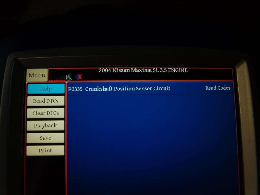
Code P0335 stored in the PCM. although the customer had not complained about it, I had noticed that there was an extended crank time before the engine started.
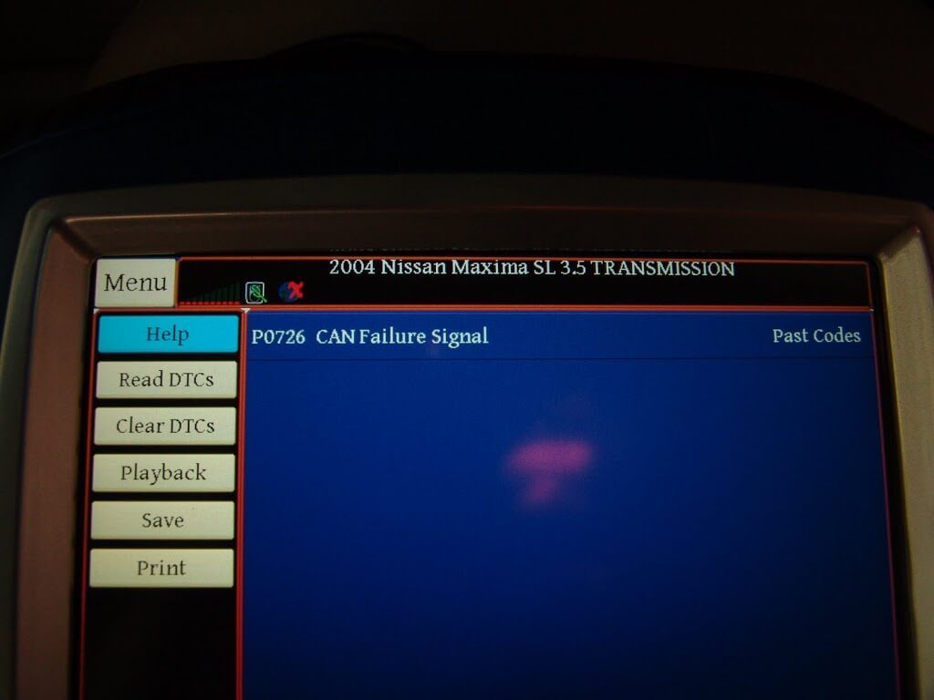
The TCM had a code P0726 stored for a CAN Failure system. In case you were wondering CAN stands for Controller Area Network. This means that there is a communication problem between modules.
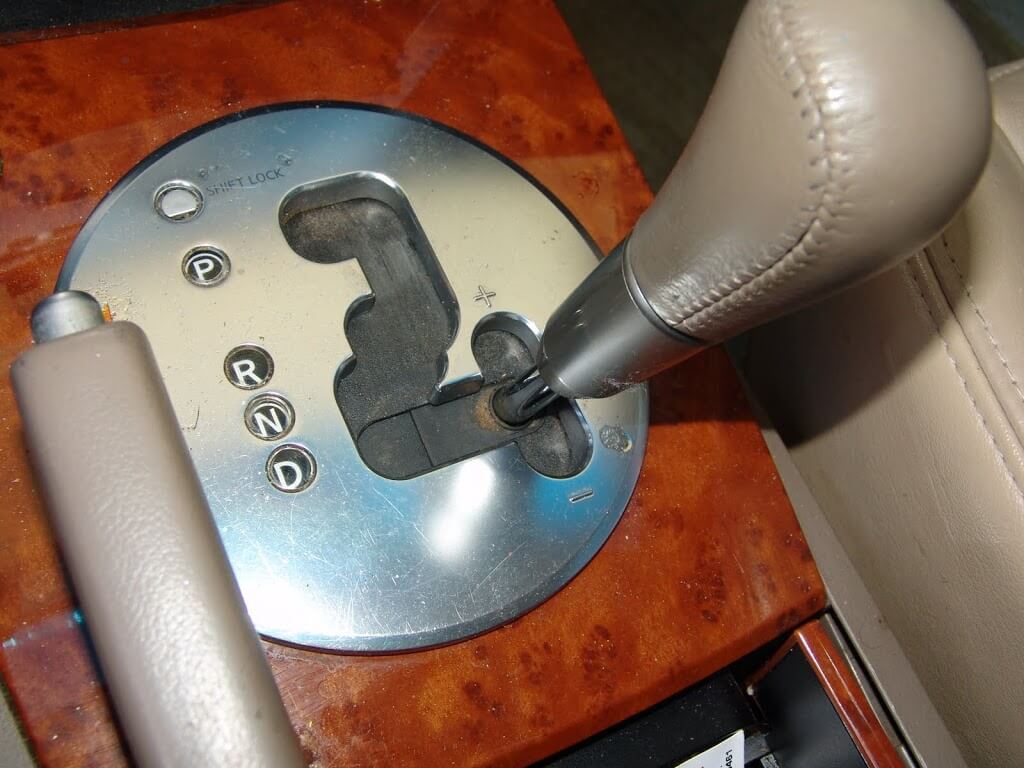
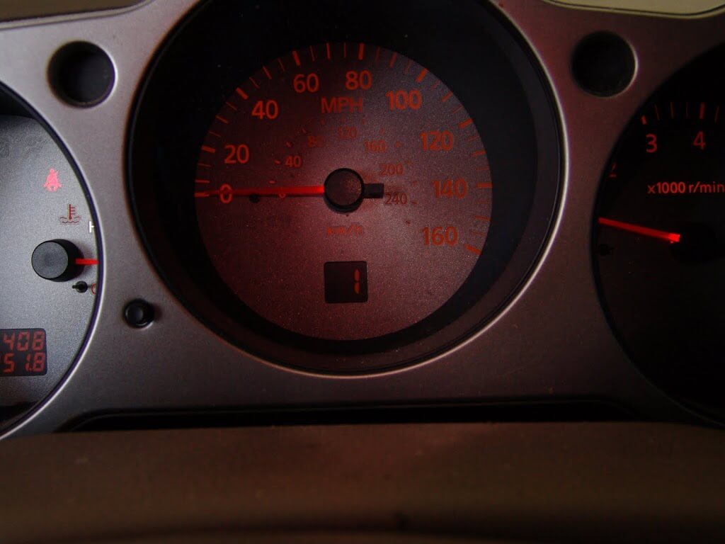
With the key on and the gear selector in the manual shift position the gear indicator in the instrument cluster shows that the transmission is in the 5th gear.
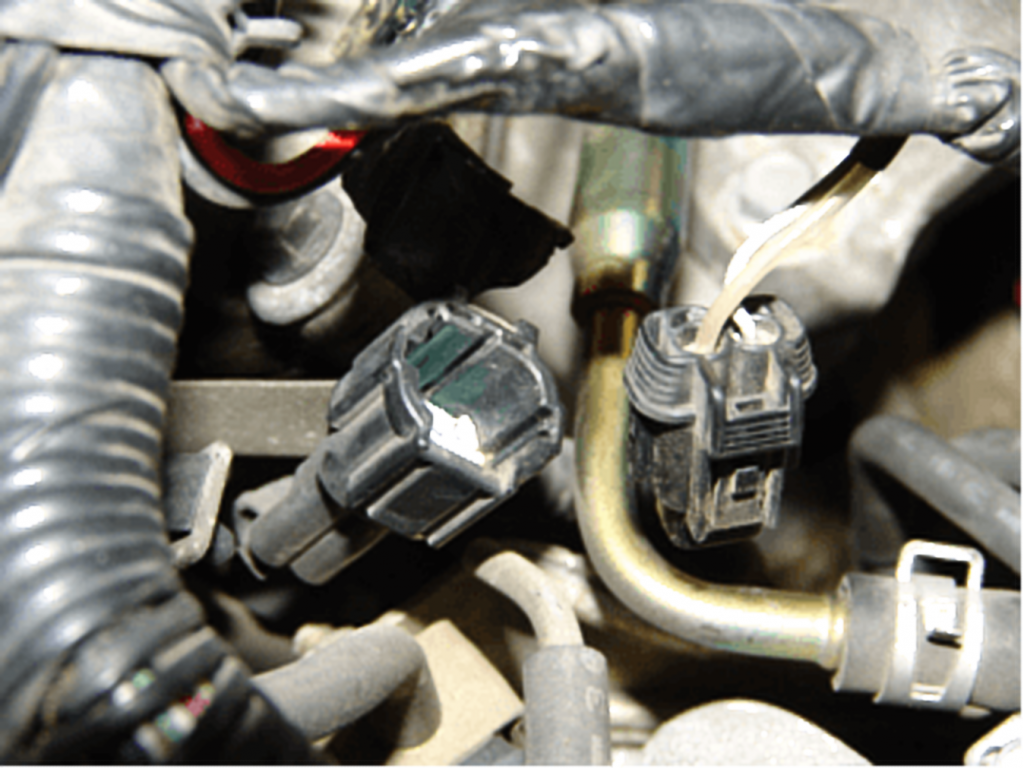
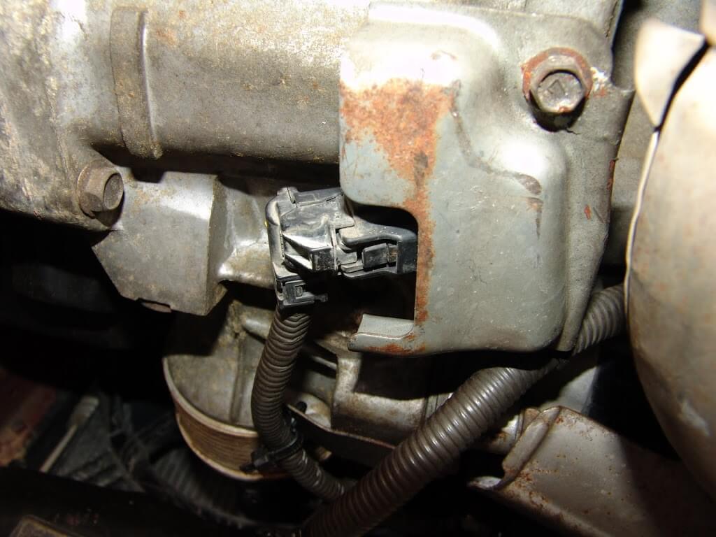
I wanted to do a little research, in that I have never seen a code P0726 before and I wanted to know a little bit more about it. I found that there are some real world anomalies with the factory diagnostic procedures. The TCM is supposed to use a crank sensor signal along with other data to determine shift patterns. The real world has found that cam sensor signals are also involved with this process. The engineers it seems did not plan on this or they did not inform the service information writers about it. Since I did have a crank sensor code I decided to start there. The crank sensor is located at the bottom center of the engine just below the flywheel area.
Everything looks okay here or does it? Kind of strange how the end of the connector looks like it is lined up perfectly with the edge of the sheet metal shield. A gentle pull revealed that it was not fully seated.
Could it be that it was that simple. This vehicle had been to two other shops before arriving at mine. Using a pry bar, I straightened out the sheet metal shield.
Then installed the connector until the lock snapped into place.
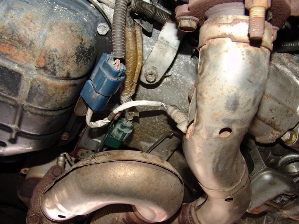
Of course while I was looking around at the problem I noticed quite a few things out of position.
Gee, you think a wiring harness laying on an exhaust pipe might cause some problems?
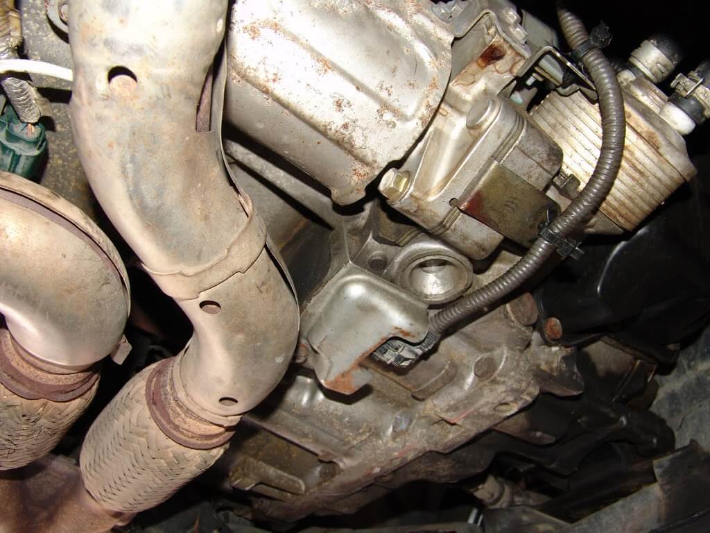
It amazes and worries me that someone can actually get an engine and or transmission in and out of a vehicle and leave something like this a mess. I had to round up a few bolts and finish installing a couple for brackets and heat shields. Then reroute the oxygen sensor wiring so that it would not be laying on the exhaust.
It does not look too bad now but I informed the customer that the engine installation needs to be gone over to make sure nothing else is loose or not installed.
Now the shift indicator shows that the transmission is in 1st gear. Both the PCM and TCM codes are now gone. The engine also starts as it should.
This one will be back in a few weeks to finish going over the wiring under the hood.
Learn the solution of the Rubiks Cube and measure your solution times with the online timer.














 As you can see, I forgot to rent the tool. Now the fun part. Crossmember. Remove the engine mount bolts, in the rear I used a long 10in extension to get to the bolt from the engine bay(intake removed). Front engine mount you need an open end wrench on one side and a socket on the other(or two sockets…) I supported the engine with a jack and a 2×4. If you have a tranny jack it would be better. Remove the 2 bolts in the front and rear(4total bolts) on the cross member and it will drop down. You can replace the mounts right now if you want too.
 Use a 14mm open end wrech to get the bottom one. On the top one, remove the hose and swap the nipple on the new rack once it is out of the car.
 Remove those nuts. Now you will see the spindle, there is a 12mm nut holding it on the spindle of the rack. Make sure the steering wheel is strait before you remove it.