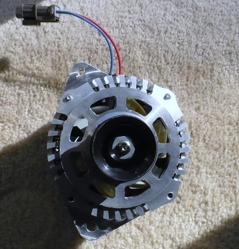
In the process of installing my supercharger (which runs of alternator), I decided to upgrade my OEM alternator to a DC Power 270 Amp Alternator. The OEM alternator is 110 amps. I paid $300 bucks for the DC 270 Amp Alternator. They usually go for $600+ according to the DC Power website.
The DC Power alternator was a direct fit to my 2004 6thgen Maxima. The installation was also straight-forward. I also did the “BIG 3” and upgraded all the wires to 1/0 gauge. This included the grounds and charge wire. I upgraded my battery to a Northstar AGM31 as well (but will save that for another post).
Please keep in mind the factory cables weren’t designed to handle the power of a higher-output alternator, and can restrict the flow of electricity (or cause cables to fry up). The “BIG 3” upgraded is highly recommended.
Fitment:
2002 -2006 Nissan Altima 3.5L V6 VQ35DE
2004 -2008 Nissan Maxima 3.5L V6 VQ35DE
Installation Photos:
OEM Alternator
DC Power Alternator vs OEM Alternator
Perfect Fitment
Additional Reference Photos:
Alternator Specs
Mounting Type
Direct fit to OEM Mounting
Output Voltage
14.8
Idle Amperage
200
Hot Idle Amperage @ 200ºF
180
Max Amperage
270
Hot Max Amperage @ 200ºF
250
Pulley
6 Groove Hard Anodized 6061 Billet Aluminum
Doesn’t affect vehicles PCM, Check Engine Light or Charge Light
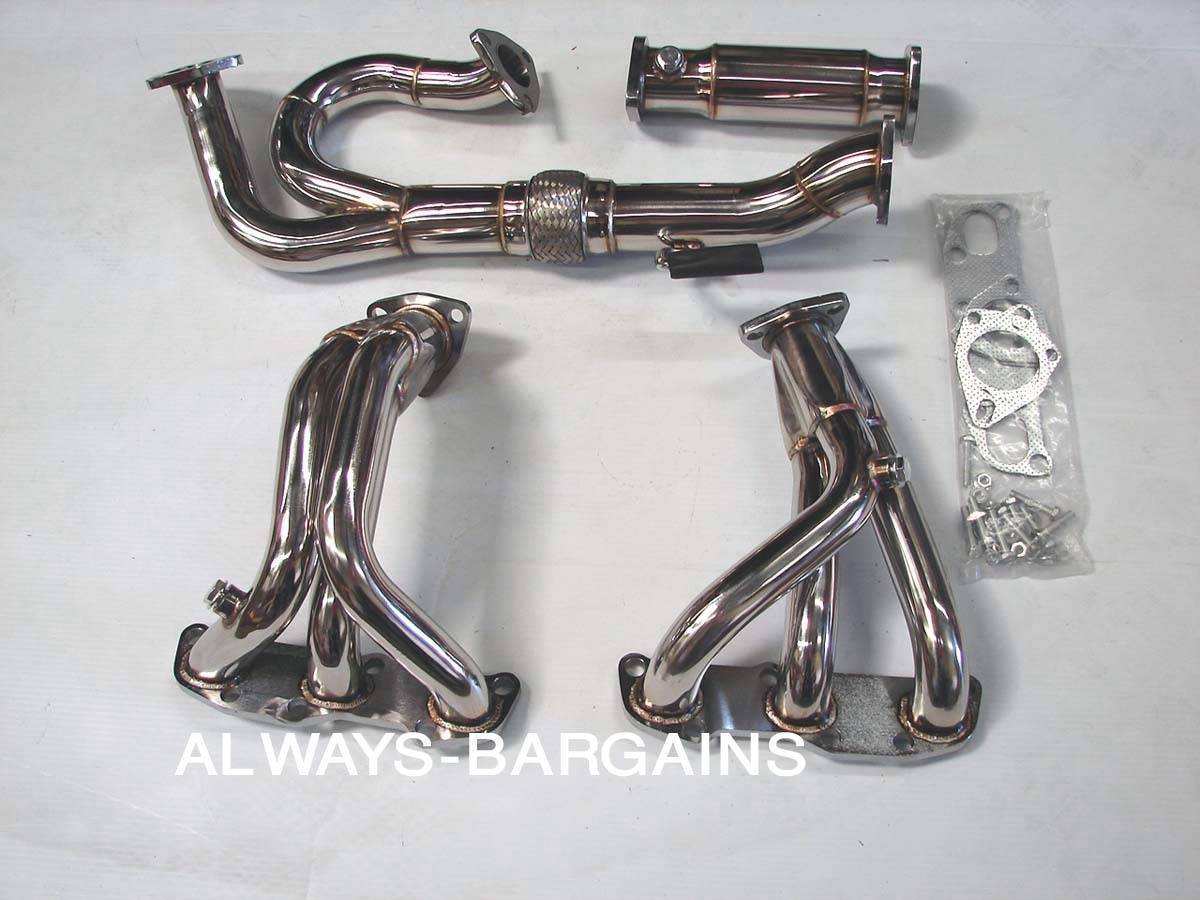
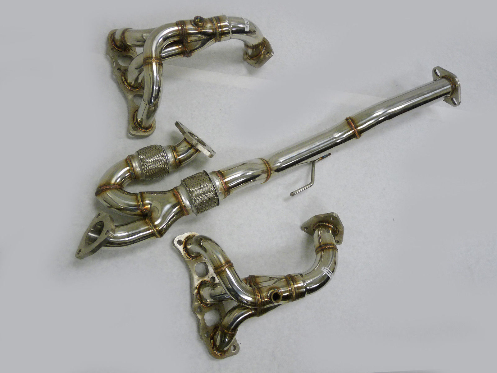
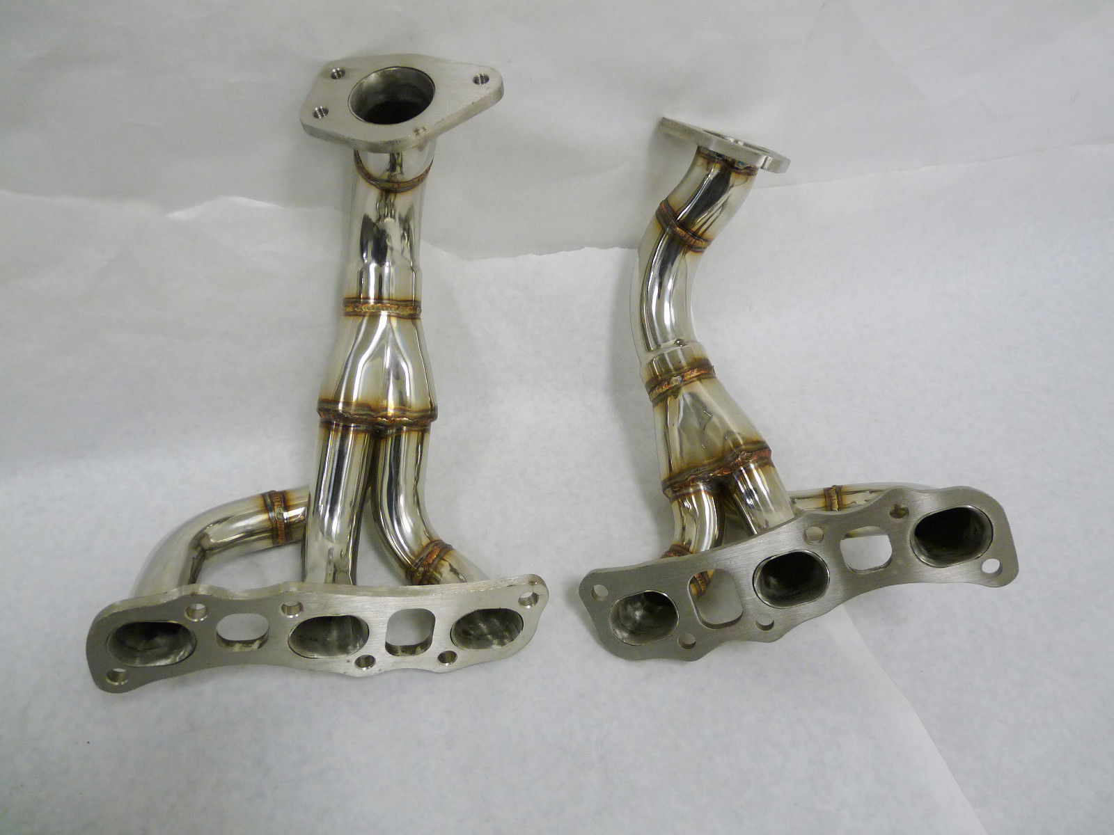
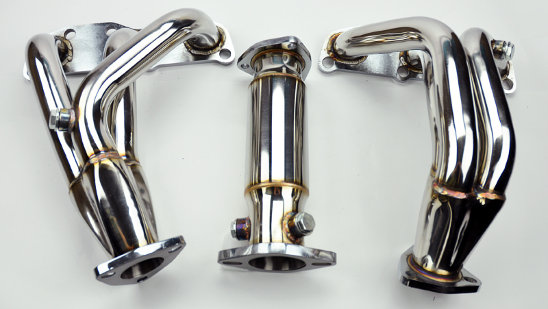
When Maxima owners get the infamous P0420 check engine light code for bad pre-cats, the best route is to go with eBay headers. However, when you search eBay there are various types of header listings that pop-up. This post goes into a little more details about what modification are required on the different types of available eBay headers.
The headers on eBay are listed as VQ35DE Altima 3.5 headers. They will work fine on all 2004-2008 6thgen Maxima’s.
So which headers should I buy for my Maxima? We would recommend going with the Manzo headers for either 6-Speed or Automatics.
General Information:
Inlet: 2″
Outlet: 2.5″
Made of High Quality T-304 Stainless Steel Material
Mandrel Bent Tubing & CNC Machined Flanges
Modification For Automatic:
You will need to shave down the flange on the header. You do not need to shave the starter as some have done but also an option. We recommend the flange itself.
The y-pipe for these Manzo headers do sit low, so many members modify it to lift it up a bit.
Weld bungs for secondary O2 Sensors. There are two sensors. You also need to extend the harness.
Weld in EGR Bung on Rear Header
If you are tuning with UpRev, then you can block off your EGR with a plate and have it tuned. You can get the EGR block-off plate from NWP Engineering for $35.00.
When properly tuned it will not throw a code. You can also add a resistor in the EGR temp sensor.
Modification For Manual:
OBX Headers are pretty much plug-n-play.
Manzo/Generic Brand Headers requires O2 bungs for secondary sensors. There are two sensors. You also need to extend the harness.
Weld in EGR Bung on Rear Header
If you are tuning with UpRev, then you can block off your EGR with a plate and have it tuned. You can get the EGR block-off plate from NWP Engineering for $35.00.
When properly tuned it will not throw a code. You can also add a resistor in the EGR temp sensor.
Extending O2 Sensors harness:
You have two options for the o2 sensors. Option is to buy the 350z o2 sensors which have a longer harness that does not need to be modified. For option 2, -f your current sensors are good and you don’t want to buy the 350z sensors you can splice you can work with existing sensors. For O2 sensors, you can either extend your existing ones or get the 350z sensors which are already extended from factors. We recommend extending the O2 harness itself versus the O2 sensor wire themselves. Many people have had success with splicing the O2 sensors with no issues given the same wire gauge was used.
Here’s some of main reason why techs do not recommend splicing the O2 Sensor Pigtails.
The O2 Sensor wire is a signal wire and very sensitive.
The O2 sensor wire is made up of material like aluminum or stainless steel and will not solder properly like copper.
Even if you manage to solder the wires, it may possibly give you weird or inaccurate readings.
By cutting/soldering/extending, you are disrupting its original properties which can be potentially sending “altered” input signals to the ECU. This can result in bad readings thus triggering additional CEL codes.
The wires are not color-coded so you have to be very careful where you splice to. The harness clip is color-coded and makes it easier to determine which wires match up to each other.
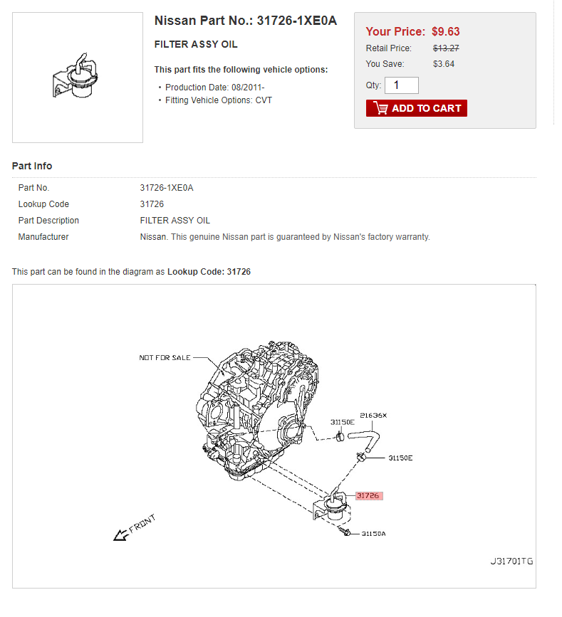
If you’re up for a CVT transmission fluid drain/refill, it is also a good idea to change the CVT transmission oil filter. Often times, if you go to the dealer and ask them to change the CVT oil filter….they will look at you like you’re crazy. Stay calm, the oil filter does EXIST! It is very easy to change and swap while you do your drain/refill.
Most dealerships are not aware of this filter replacement because Nissan does not call for this maintenance change in any of their maintenance intervals. So to their credit, it’s not their fault that they are unaware. However, for $10 bucks this is something you can do yourself or dealer as part of your transmission fluid drain/refill.
Part Number: 31726-1XE0A Part Name: FILTER ASSY OIL Price: $9.00-10.00
It is located behind the splash shield in the driver’s side wheel well. It’s held by a 10 MM bolt and two hose clamps. Simple enough!
I purchased this slightly used from the classifieds here for a price that made it worth trying out.
There have been nearly a dozen threads over the last couple of months describing how intakes on our cars just bring hot air into the engine.
The R2C utilized the factory snorkel as well as a heat shield that is gasketed to keep out excessive engine heat.
I am running the black hex filter line, which appears to be an upgrade from R2C. They claim 10hp increase, which I don’t really believe. Their website shows dyno graphs of the increase as well as intake temperature staying identical from stock and after install. Their website dyno charts show the increase starting about 3800rpm, but a decrease till about 3000rpm.
Currently I have a Racingline y-pipe and Stillen light weight under drive pulley for engine modification. Over the next week I will determine if this is just noise or if there is an increase in performance.
We know that if I start getting better mileage, there is a good chance I have lost hp.
Install was very straight forward and took about 30 minutes. Now, I used to work on cars for a living, so if you don’t know what you are doing, or what tools you need (the directions didn’t have the right tools listed) then it will take you 60-90 minutes to complete.
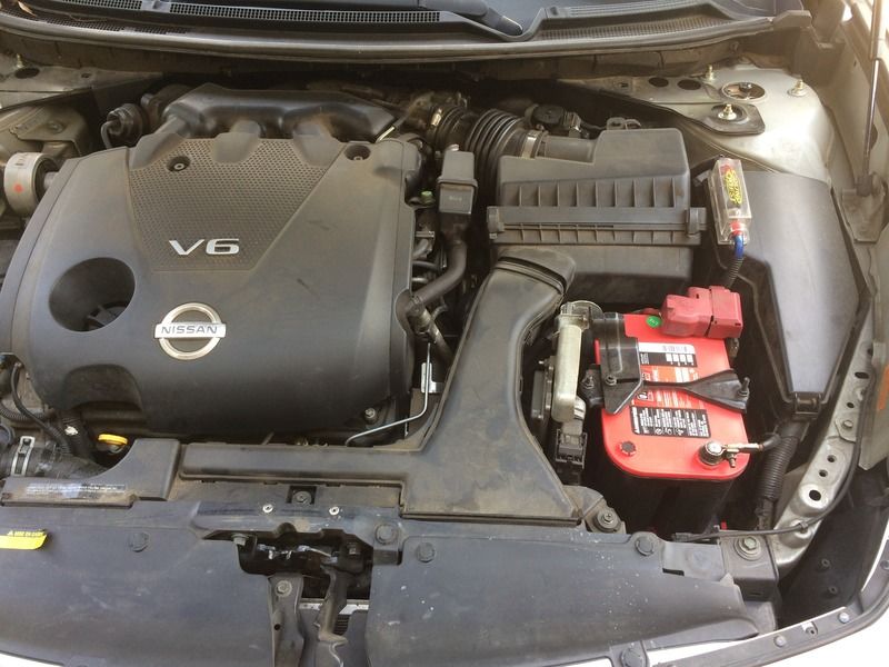
Before:
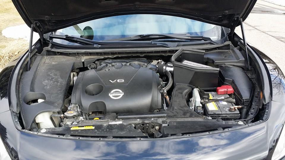
After:
Initial impressions from install:
The heat shield could be a little more robust. It covers the entire hot side, but I would have finished the box and enclosed the filter a little more. The filter is solid, and I have no doubt it will last the life of the vehicle. Assembly can be a little confusing from the directions.
Initial driving impressions:
Noise. It is definitely louder than the stock box. Resonators on the breather hose and air box are eliminated, as well as the ‘sound tube’ if you still have that on your car. The open design really let’s the motor sing in the cabin. It made me feel like my exhaust sounded better as well, but I’m sure that was just the added engine roar.
There is some low end torque lost. I can still chirp the tires, but nothing like before. To me, it feels more like a ramp up of power being applied. I did not (un scientifically) notice a change in my 0-60 times. If I did gain power, it is above 3500 rpm. That felt better, but it may be placebo from the extra sound. Boy, it sure does sound faster.
And now for some hard core knowledge from someone much smarter than me: This is a copy/paste with a little editing, so some context may be lost.
There are three aspects here:
1) intake air temperature, which we will assume is similar although I haven’t seen any data
2) Restriction across the air induction system–which we will assume is lower if it is performing as advertised
3) dynamic tuning effects–the likely factor here
So your Maxima has the high output version of the transverse 3.5 liter port injected V6. Unlike the cheaper Altima version it has the exhaust variable cam phasing (VTC) and two different actuators for resonance tuning. One actuator changes the length of the runners. Another actuator changes the volume of the intake plenum, the collector. This architecture is very different from the 3.5 liter longitudinal mounted engine used in say the later 350Z: that engine has exhaust cam phasing but has independent intake systems for the different banks.
Now recall that there are pressure waves that occur in the intake system. For our purposes there are two effects:
1) Intake air reflected backwards as the intake valve closes–air hits a wall and reverses direction
2) Intake air pushed back into the intake port as the intake valve opens during overlap. This one’s a little harder to visualize so here’s a diagram:
See that little “Pint” line? That’s backflow into the intake port during overlap. If the intake valve opens before top dead center the piston is still rising. If sufficient exhaust gases remain in the combustion chamber and exhaust pressure is higher than intake pressure there will be backflow into the intake port as the piston rises. The backflow will create a pressure pulse in the intake port that can be timed to push air into another cylinder as its own intake valve is closing.
Keep in mind that the general rule of thumb is that shorter piping length (including induction system before the throttlebody) tends to result in more sharper peaks that fall off early. Longer piping length results in fewer peaks and better higher rpm breathing. The Maxima has an actuator that switches between runner lengths to get a broader torque curve.
The Maxima does NOT have an actuator to adjust the length of the intake pipe leading up to the throttlebody (air induction system). Its geometry is fixed. When you change that, you change the pipe tuning effects. Some engines do have a variable air induction pipe length. The Rx-8 is one of those – I covered it in my thread.
Now keep in mind that much of this runner length effect is related to the intake valve closing timing (the pulses reflected when the intake valve shuts). The overlap effect gets into valve timing and scavenging effects. That has its own set of optimization that needs to be done regarding cam sweeps. I’ve covered a cam phasing sweep in page 7 of my thread, in the context of fuel economy, but it works for performance as well. So the valve timing can be optimized in simulation and it can be tested on a dyno, preferably an engine dyno where port pressures and cylinder pressures can be sampled on a crank angle basis.
The plenum can dampen the pulses and/or provide a reserve of air that can be drawn in. The general rule of thumb on an n/a engine with 1 collector is that larger plenum volume = better for high rpm, smaller plenum is better for low rpm. So you’ve got an actuator that switches between the conditions.
There’s a chance you could restore some of the lost low end torque if you adjusted the VTC tables to change pulsation effects and scavenging, and/or moved around the switchpoints for the variable runner length and variable plenum actuators.
Also, this is an open element style filter right? And the factory air snorkel is just sort of showering air on it, rather than a sealed airbox design like stock? That right there shortens the effective length of the pipe, in addition to the loss of any plenum like effects from removing the resonance chambers. A larger pipe will also have more static effect (less pressure drop) at higher rpm, because pressure drop increases exponentially with airflow. See page 6 of my thread for a chart.
Unfortunately those are not well put together dyno sheets on the manufacturer site. They are busy and hard to read. And I really don’t like that it started at such a high rpm for the pull. It is missing the scavenging area under 3000rpm which is heavily influenced by Exhaust VTC tuning for additional overlap. Chassis dyno operators are scared or unconcerned about low speed full load but I’ve seen OEM guys agonize over it and make big changes to optimize torque at 1500 rpm. If you’ve got a loading dyno, start at 1200-1500 and run to redline with the dyno brake ramp control. It gets a more consistent pull. You’ll see pulsation and tuning effects a lot more.
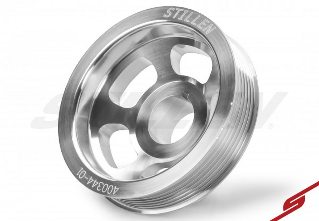
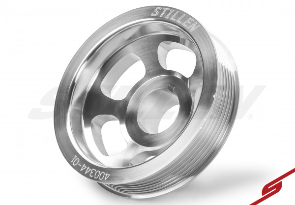
STILLEN has long manufactured precision pulleys for our supercharger kits. We have used this expertise to produce a new line of high performance crank and accessory pulleys.Each pulley is machined from 6061 aerospace grade billet aluminum with a bold new design to maximize performance, strength and minimum weight. 304 stainless steel sleeves are used for main seal contact points for durability. Stock timing marks are maintained and keyways are precision broached. All pulleys are CNC turned, milled and balanced based on computer generated designs. Up to 80% lighter weight than stock steel and up to 10% lighter than other aftermarket pulleys, we’ve seen power gains of up to 10+ HP at the wheels.Both underdrive and stock diameter applications available for most popular Nissan / Infiniti vehicles.
Product Features
Underdrive Crank Pulley
Billet Aluminum CNC Machined at STILLEN
OEM Pulley Weight: 4.32 lbs.
STILLEN Pulley Weight: 1.00 lbs.
Approximate Underdrive: 20%
Shorter Belt Required and Sold Separately
Not CARB Legal **Not For Sale in California**
I had been very against Underdrive pulley installation in the past. On my previous vehicles, this instal would mean that the harmonic damper was removed, and vibration and engine wear were increased. I had also seen limited improvement or gains from the mod, and felt it was purely aesthetic while potentially harming the engine and limiting alternator output.
Then I found that the VG 3.5 has an internal damper and the crank pulley is only a pulley. I have read arguments that the delrin insert in the stock pulley helps act as a damper. Based on my knowledge of the insert material, I didn’t see this as a concern.
Underdrive/ light weight pulleys work by reducing rotational mass. They do not add power to the engine. They do, however, reduce what is known as drivetrain losses. If less power is needed to spin the pulley and accessories then more power is available to be sent to the transmission. What that means is that my Engine HP did not increase at all. WHP will go up though.
I have been looking for mods to add, that don’t require taking the engine apart. I picked up one of these pulley and belt combos from the classifieds as NIB, for a much better deal than new from Stillen. I was very skeptical that this would work, but for the fairly small amount of money involved I figured I would try it.
I had my dealer install this. Generally I do the installs myself and document them for the forums, but I was feeling lazy and the dealer price wasn’t that out of line. My dealer charged $157 to install the pulley and new belt. This involves removing the wheel and fender liner, the starter, and then the pulley itself. Book time is 1.5 hours.
Impressions:
First thought: Interesting. Second thought: the throttle limit till 30mph really limits this car. Third thought: holy crap, this actually worked.
When not really on the gas, and at lower rpm this isn’t noticeable. When I am on the gas, above 3k rpm, there is an increase. Rule of thumb is that 5hp is the smallest increase that is registered on the butt dyno. I fully believe the 10hp claim, and feel this probably added as much as my RacingLine y-pipe. The engine does not seem to rev faster, and I attribute that to the transmission. The car does accelerate better, and I would say slightly smoother as well.
$135+$43= $178
Installed by dealer would be $335.
Is it worth that? Potentially. I am very happy with this mod. Knowing what I know now, I would probably do it again, and have no problems recommending this to everyone on the forum. If you are looking for a fairly cheap power adder, and for one of the few things available for this engine, then this is a very good option.
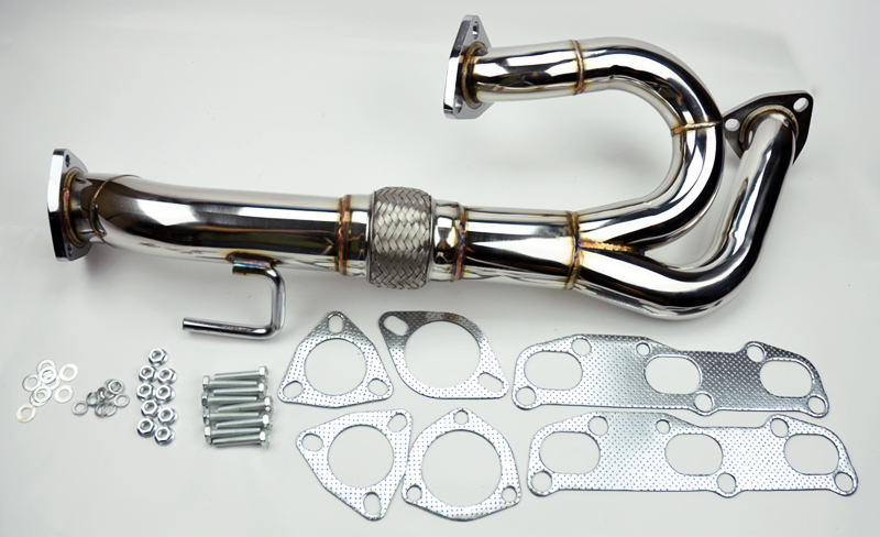
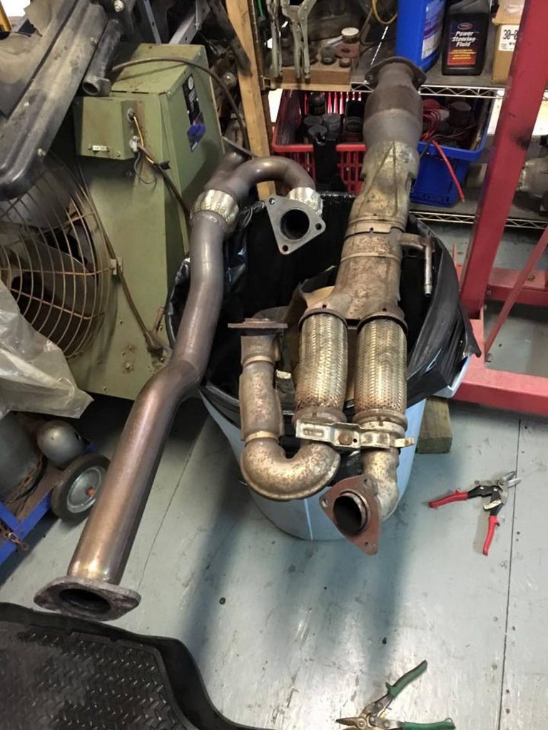
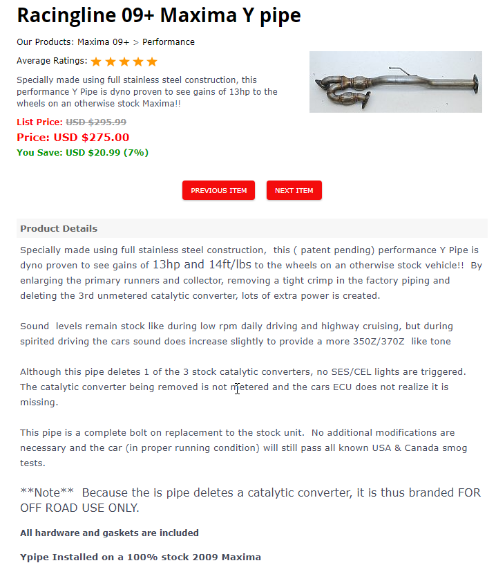
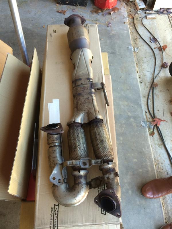
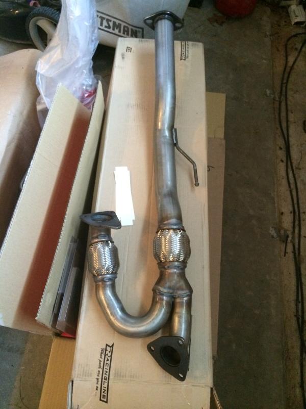
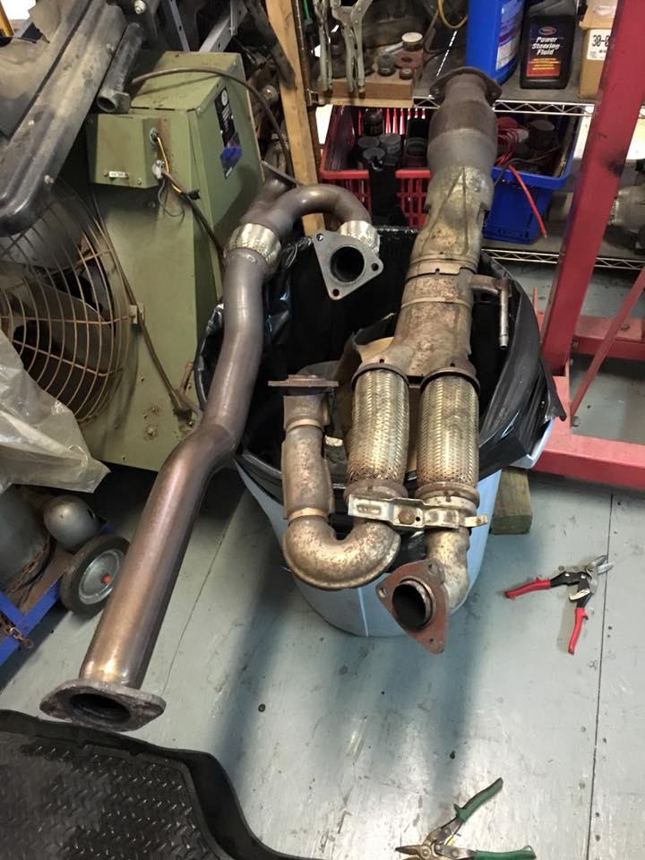
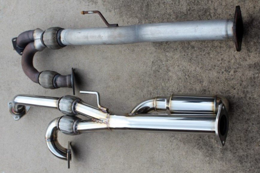
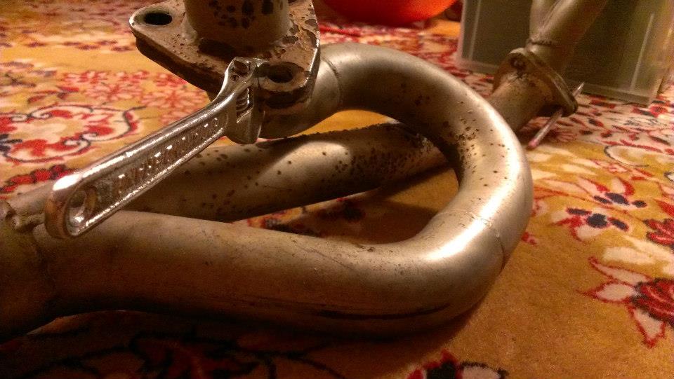
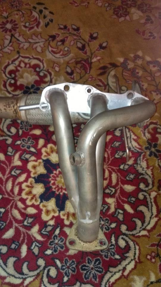
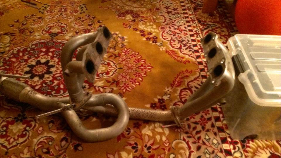
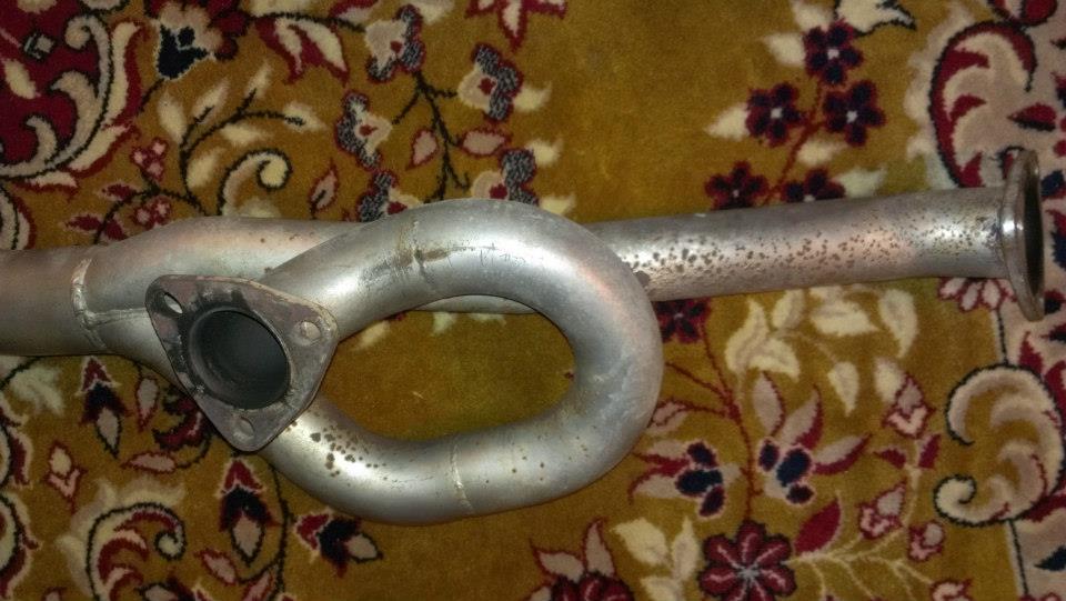
The factory pipe is about 1″ thick after the flex pipe section. The tight u-bend is significantly more restrictive than the larger bend, and the diameter of the pipe is much more consistent. When ordering, you will need to get the gaskets, either from them or a parts store.
You will also need to go to the hardware store and pick up the following:
2x 10M-1.25 x30mm
2x 10M-1.25 nut
2x 10M lock washer
The factory has studs to the mid pipe, while the RL pipe just has holes.
Notes: Please refer to the factory service manual for additional information on removal of additional items.
Remove the crankshaft pulley as follows:
Step 1. Disconnect the battery, raise the front of the vehicle and support with jack stands.
Step 2. Remove the passenger front wheel
Step 3. Remove the splash shield covering the crank pulley and remove drive belts per factory manual.
Step 4. Remove starter motor and lock the ring gear in place.
Step 5. Loosen crankshaft pulley bolt until it is ¼” from the surface of the pulley. Do not remove crankshaft pulley
bolt completely as it will be used as a supporting point for puller.
Step 6. Using a suitable puller, remove the crank pulley.
Install your new crankshaft pulley as follows:
Step 1. Lightly coat the inner diameter of the crankshaft pulley with anti-seize. Install crankshaft pulley, taking care not to damage front oil seal.
Step2. Holding the ring gear, initially tighten crankshaft pulley bolt to 33 ft-lbs.
Step3. Place a paint mark on the crankshaft pulley (a) aligned with the one of the angle mark on the crankshaft bolt (b). Tighten the bolt until it has turned 90 degrees and the next mark on the bolt is aligned with your paint mark.
Step 4. Reinstall starter, new belts (tightened per factory manual), splash shield and wheel. Lower the vehicle and reconnect the battery.
Step 5. DONE! New belts will need to be re-tightened after a couple of hundred
miles.
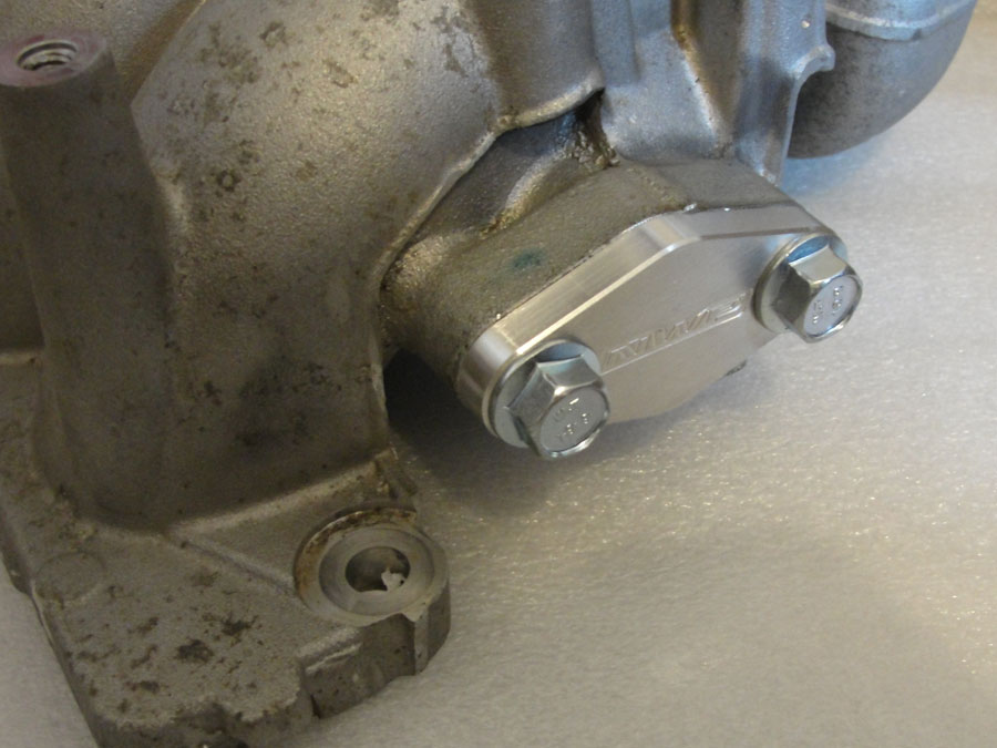
Below is the information seen in the Nissan factory service manual (FSM) for 2002-2008 VQ35DE Nissan Maxima’s. This information can be found in the “ENGINE LUBRICATION SYSTEM SECTION – LU” section of the factory service manual.
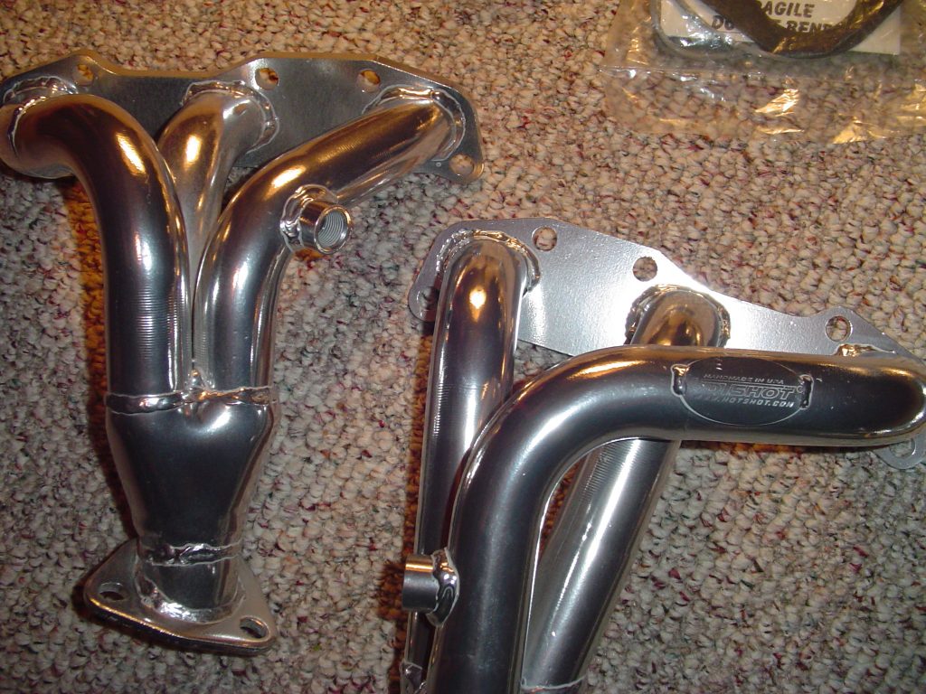
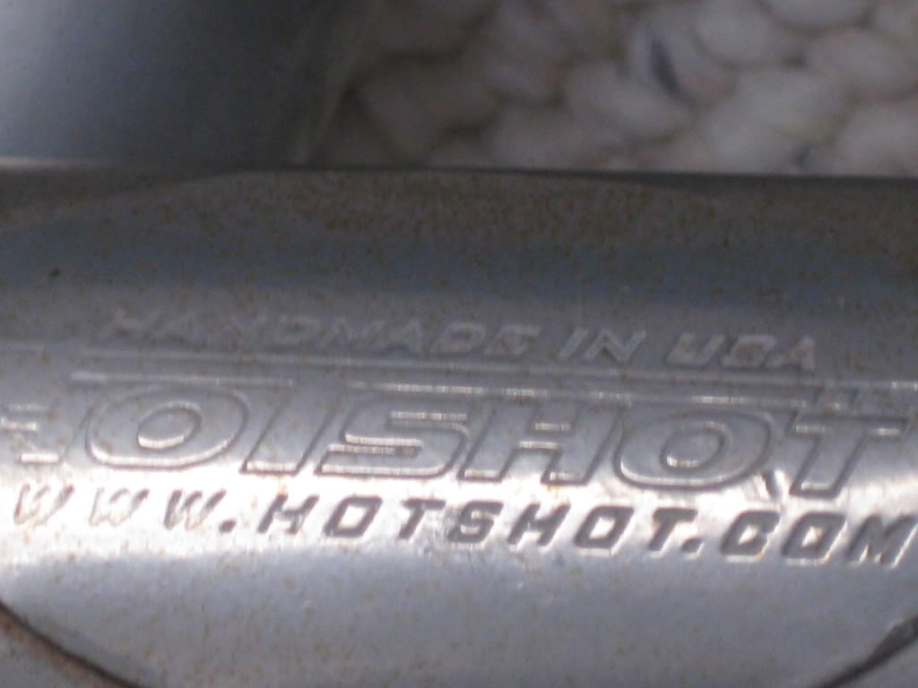
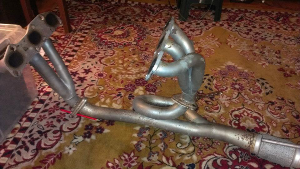
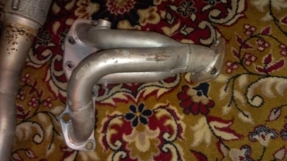
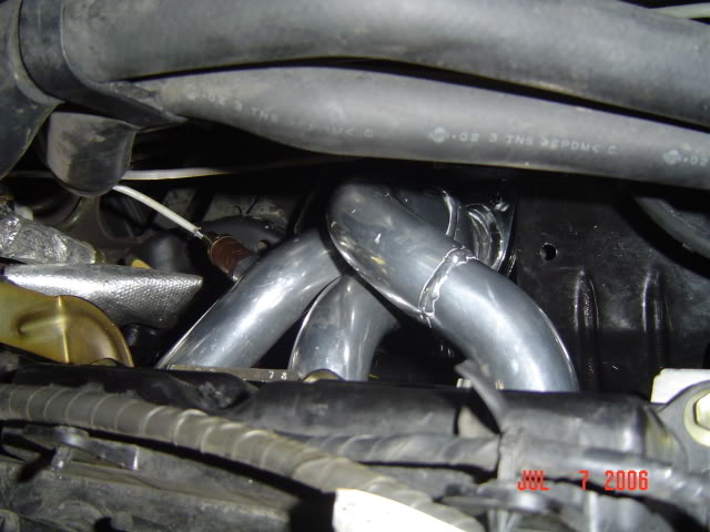
These headers are no longer in production. They were available between 2004-2007 and are very rare to find these days. The information below is only for reference purposes.
Part#: NS3017
System Components: Includes 2 headers and one secondary with flex-pipe. System also includes 2 center copper gaskets,cat.gasket, all necessary hardware and O2 relocation wire kit.
Finish: Thermal ceramic coating Color: Hi gloss Silver
Price: $549.00 US Dollars
Installation Instructions:
Installation time: Aprox. 4-5 hrs. to remove stock manifolds and aprox. 1-2 hrs. to install Hotshot header.
NOTE: All Hotshot Performance items are intended for off road use only. Hotshot Performance will not be responsible for any consequences resulting from your failure to comply with your federal, state, and local laws. Hotshot Performance recommends that trained professionals perform the installation of mechanical parts, as improperly installed products may lead to unsafe and unreliable conditions. Warranty will not be honored for damage or malfunctions due to improper installation, misuse, unauthorized repair or alterations.
1) This header was designed to be installed from underneath the car, requiring the removal of the stock manifold, down pipe, cross member and power steering bracket. You will need to jack the car high enough (or use a car lift) to slide the header under the car and lift it into place. Be sure to let the car cool down COMPLETELY before attempting to work anywhere near the exhaust system.
2) Start by disconnecting the battery ( you will be working near the alternator), and spraying all nuts with rust buster. Let it soak at least 1/2 hour or you WILL break something.
3) Remove stock manifolds and down pipe. Disconnect and label O2 sensors (front manifold, rear manifold, etc. ) The rear header is easier to remove if you take it apart.
4) Remove power steering bracket for removal of manifold, and donŐt re-install it or it will rattle on the headers.
5) Install headers, and put on nuts finger tight only. Leave ALL nuts loose. You can re-use the stock gaskets.
6) Line up Y-pipe with 2 headers and cat. Converter before attempting to install it. Once everything is close, start by installing the front gasket and 3 bolts (leave them loose) then the rear. Only bolt the y-pipe to the converter after the headers are located correctly on the y-pipe. Be sure to use the new cat gasket.
7) Tighten all nuts evenly, starting with the headers and working down. .
8) Extend O2 sensor wires using supplied kit. Be sure to cut and splice wires one by one to make sure y9ou do not get them mixed up. Install O2 sensor into fitting and tighten securely. You will need to have the 2 supplied O2 bungs welded into your exhaust system AFTER the cat in order to NOT get a CEL (Check Engine Light).
9) Check for loose connectors, and re-connect battery
10) Before starting car for first time, wipe header down with mild solution of soap and water to remove any grease or fingerprints.
11) Lower car and start. Check for leaks. A leak will sound like a steady sputtering, and you will be able to feel pulses of exhaust. If you do not feel any exhaust pulses, and you think you have a leak, it is probably just the difference in sound form the stock manifold compared to the race header.
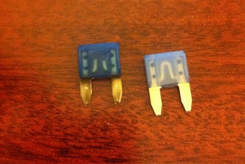
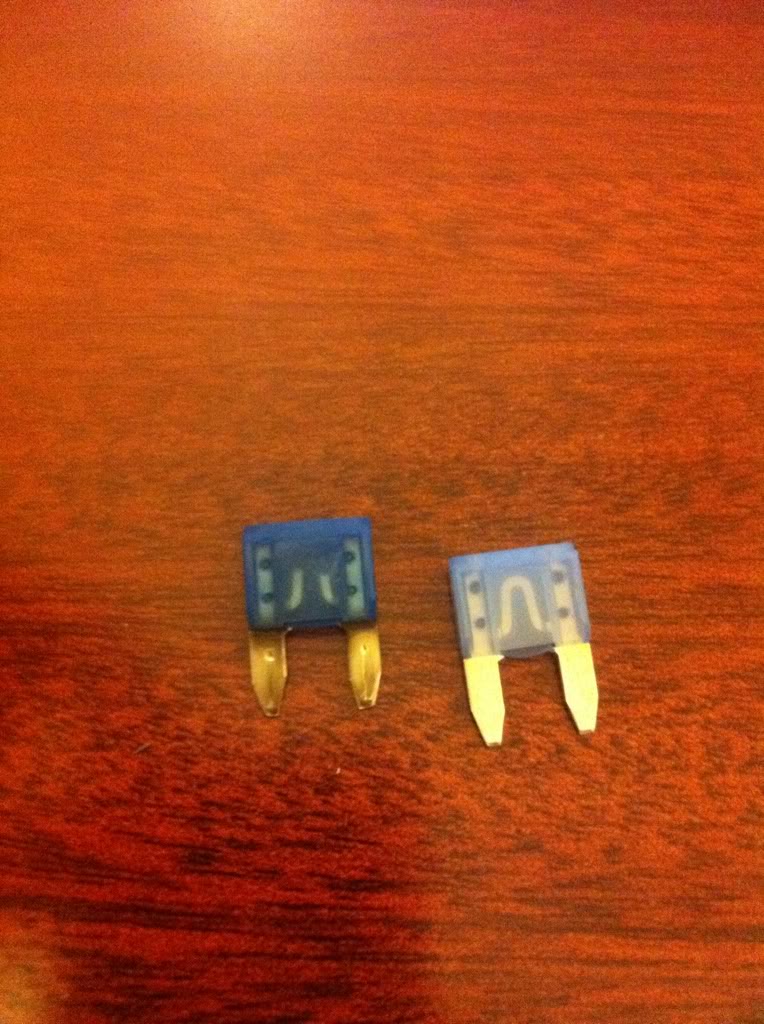
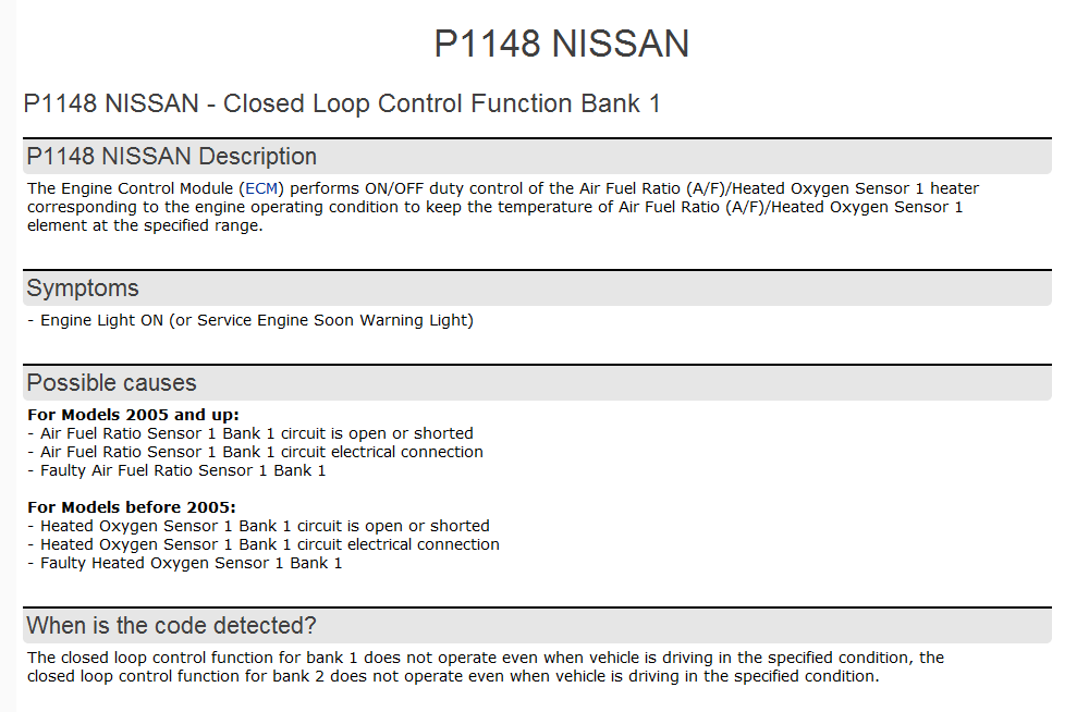
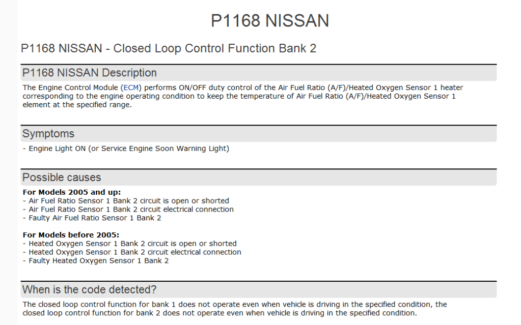
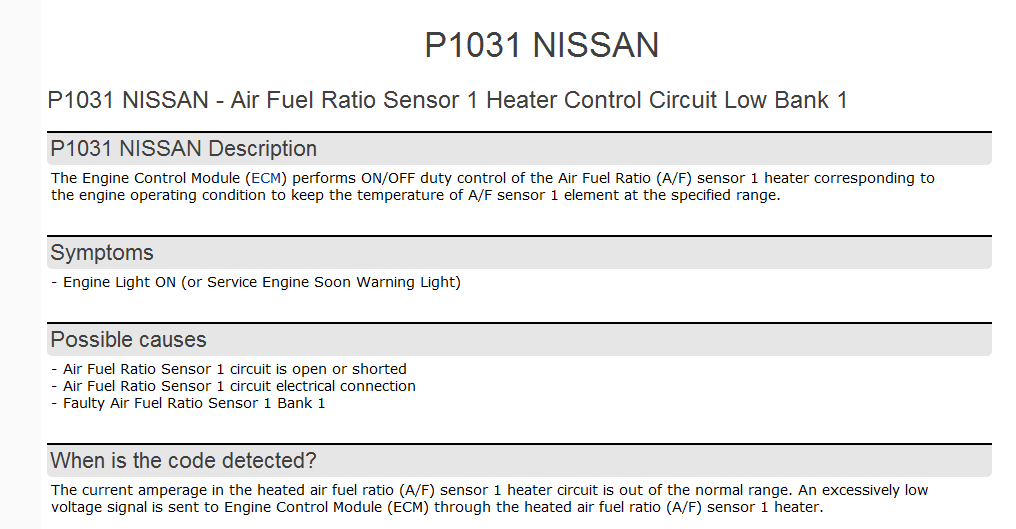
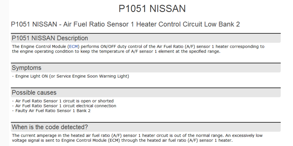
I was getting all of these codes at once. Before replacing anything, I decided to do some simple diagnostics and checks. I checked my 02 Sensor Fuse and surely it was BLOWN. I replaced the fuse and all these codes were gone. No more P1148, P1168, P1031 and P1051.
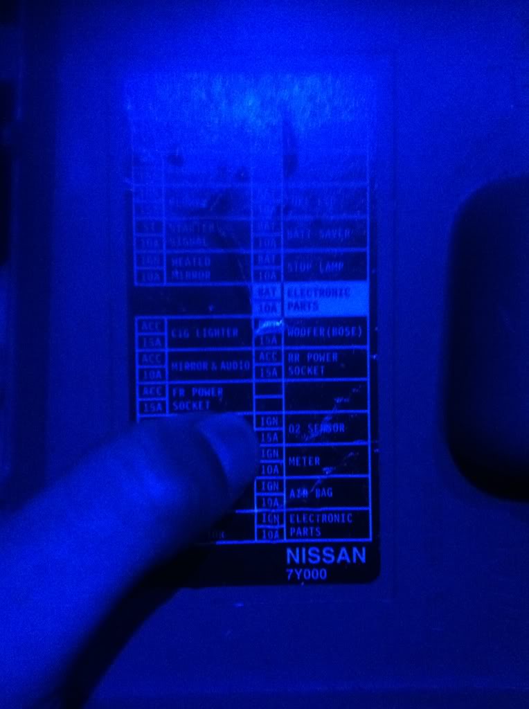
Check your fuse panel under the dash and look for the 15A – O2 Sensor fuse. Reference photo below: