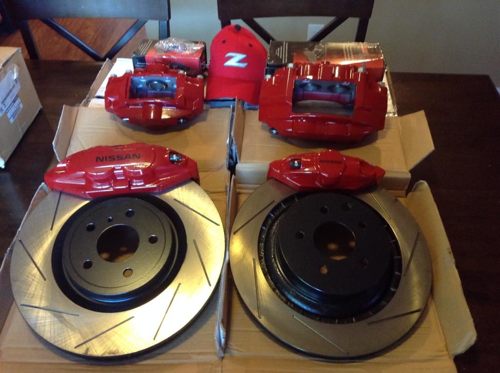
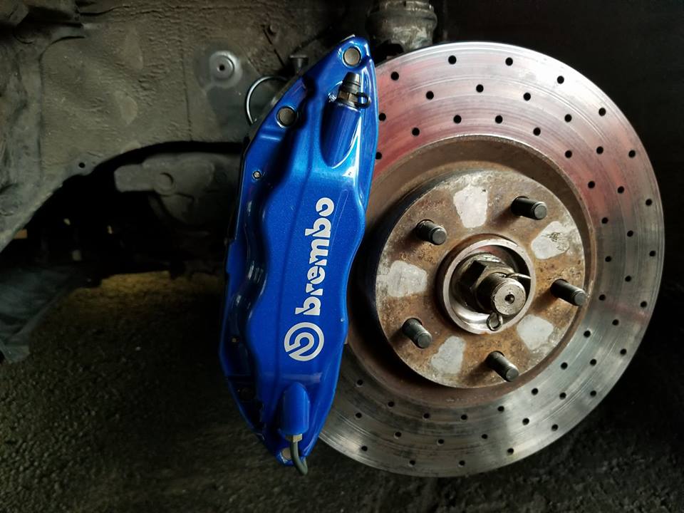
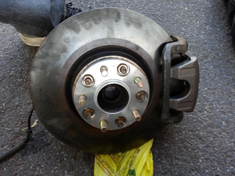
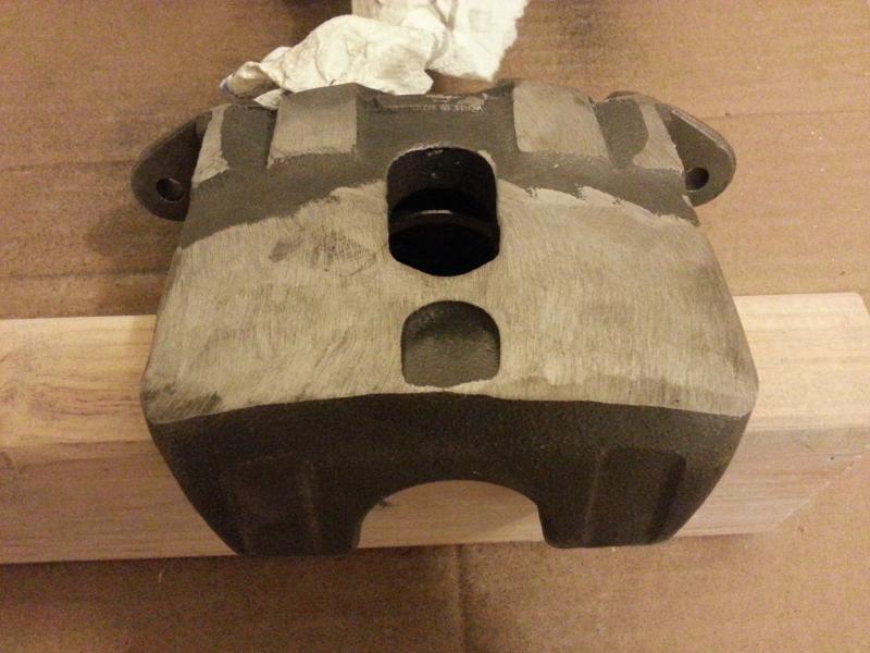
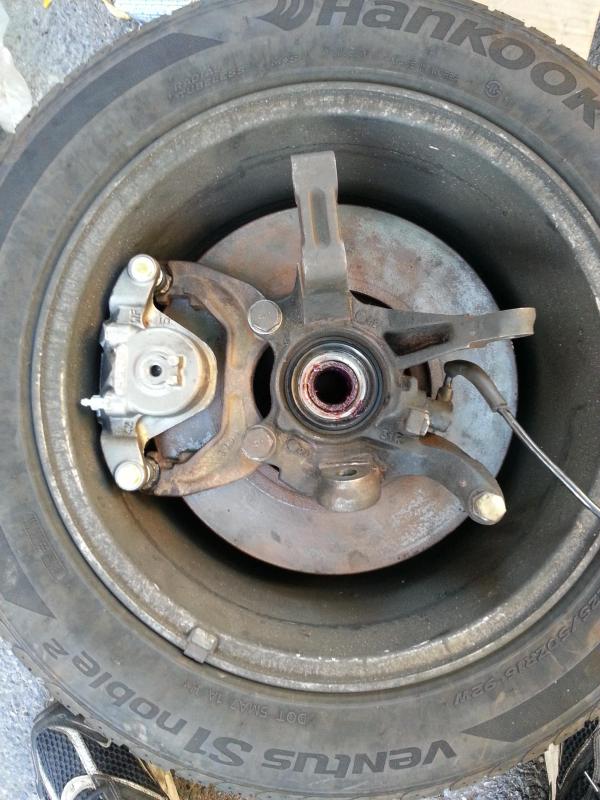
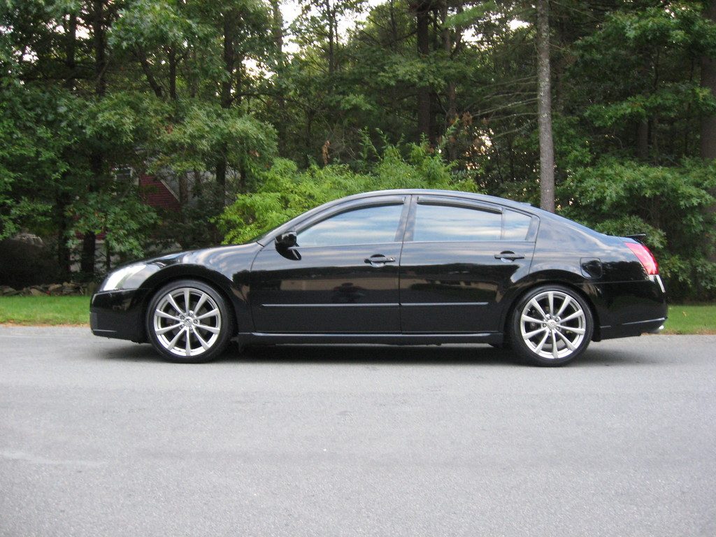
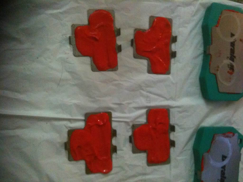
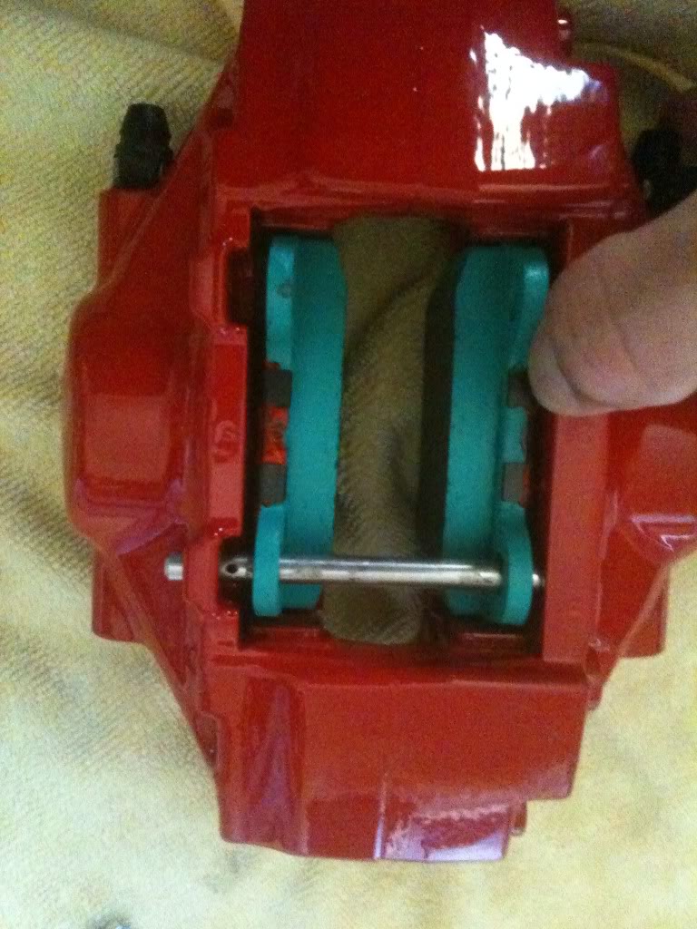
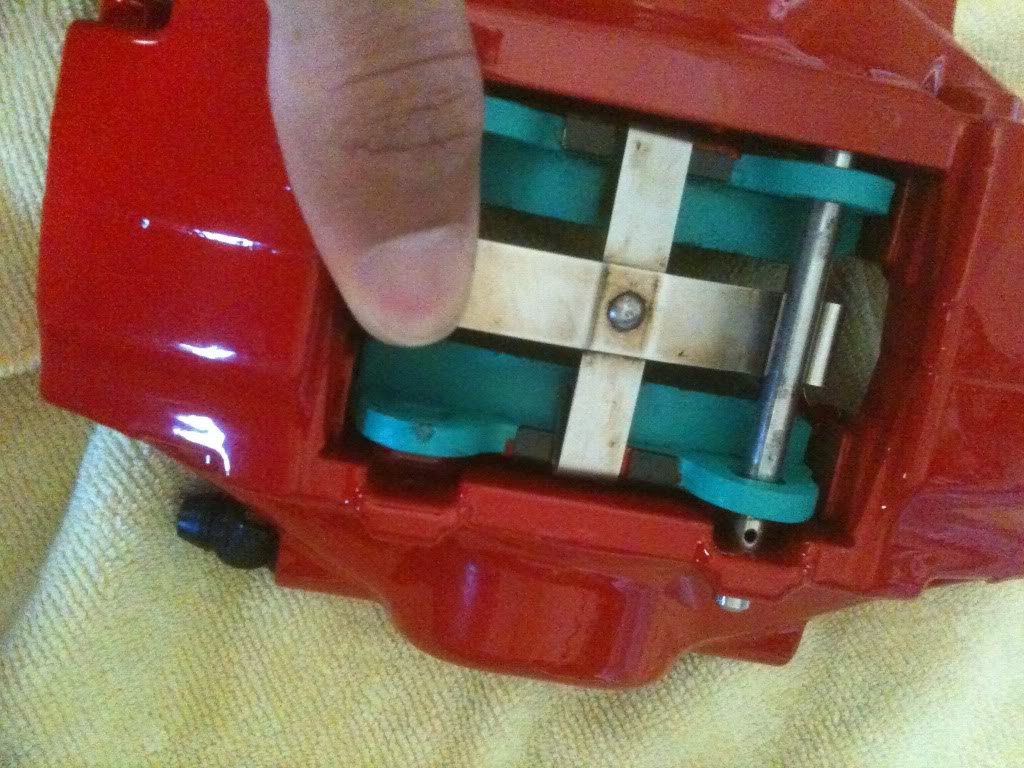
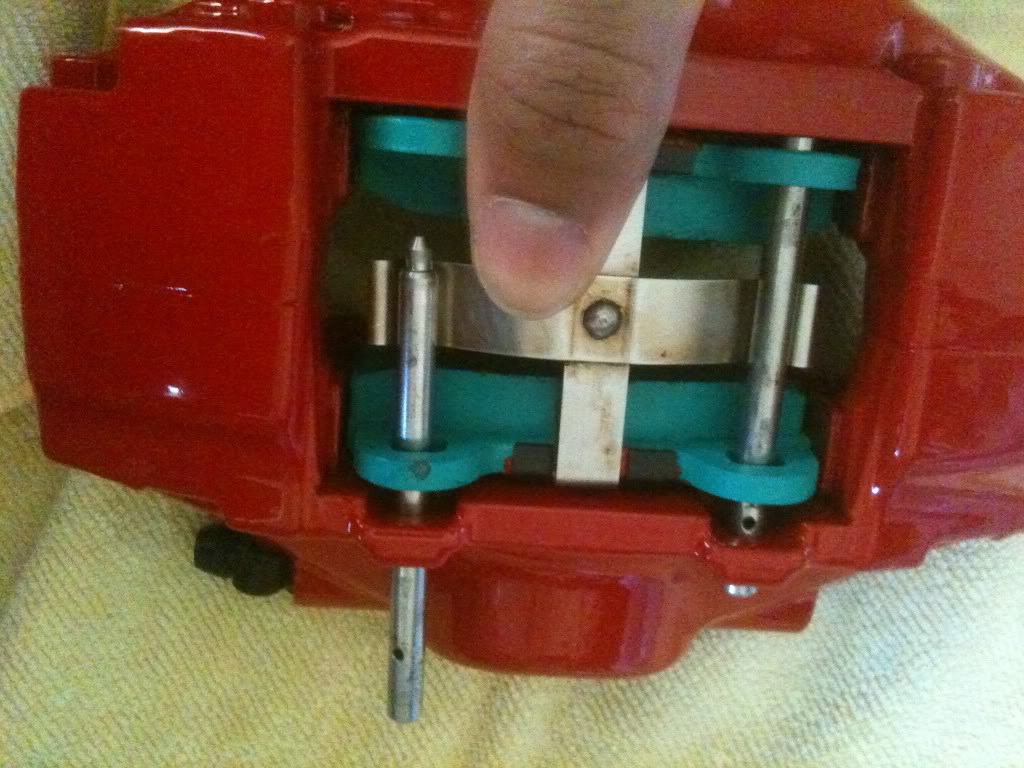
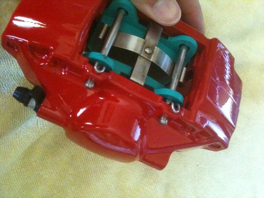
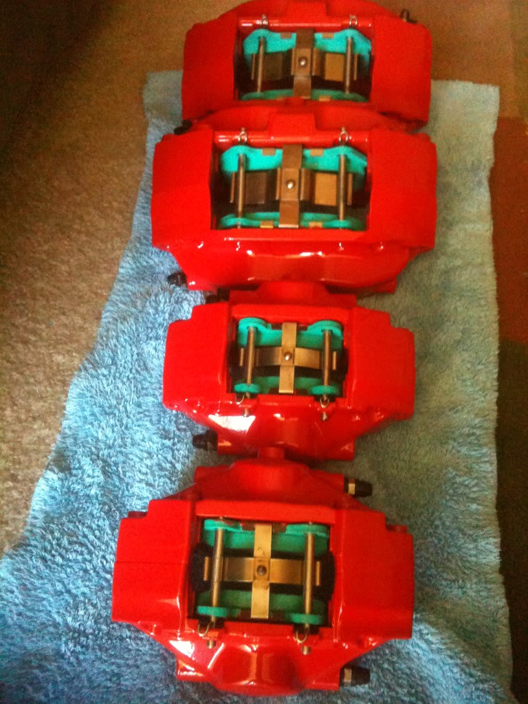
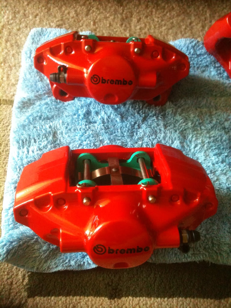
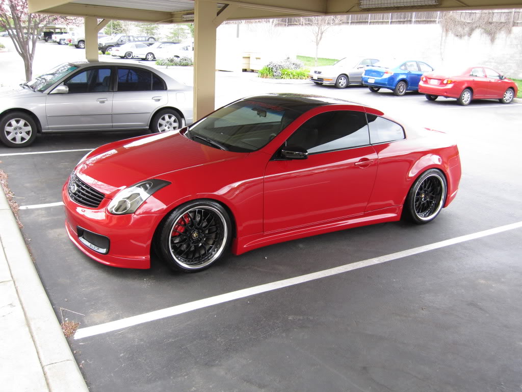
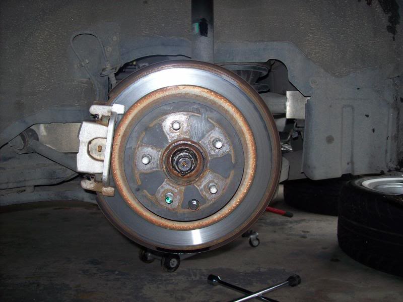
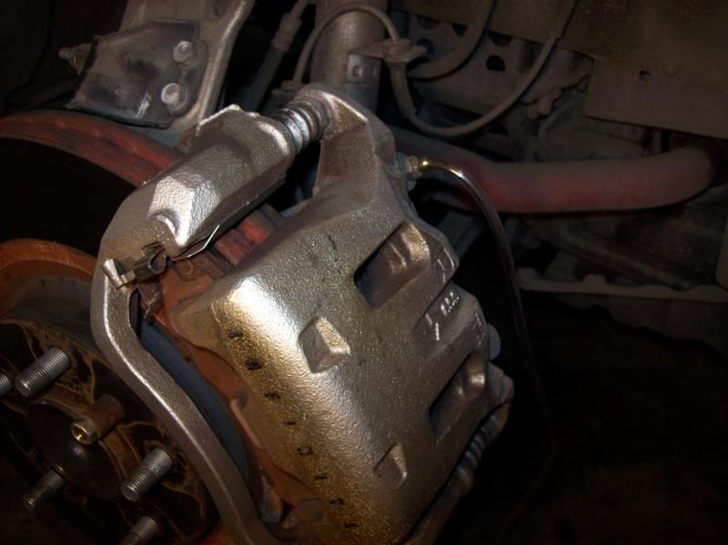
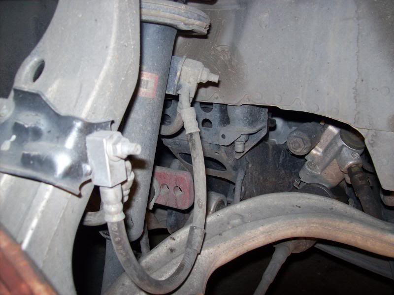
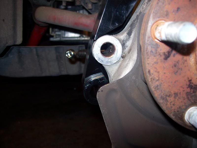
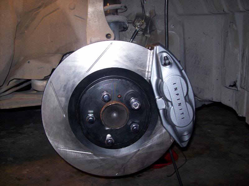
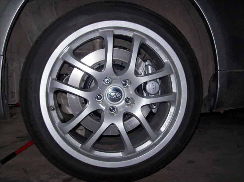
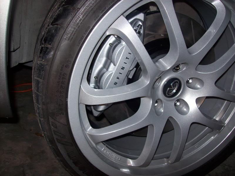
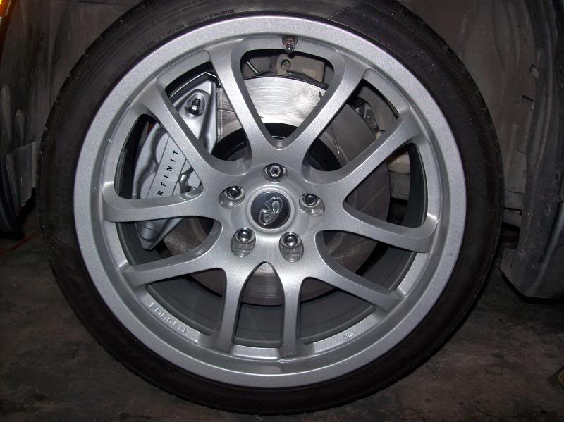
Both the Nissan 370Z and the Infiniti G37 calipers are the same size, simply done in different colors respectively. They both will interchange 100% with each other, and all hardware remains the same for both calipers.
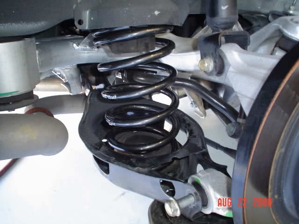
This installation process is for a set of Eibach Suspension Springs Pro Kit 6369.140 with 2.0″ drop in front & 0.8″ drop in rear.
REAR END: 20-30 minutes
Tools Needed: Air rachet or air gun, 18mm socket 3/4″ open wrench & adjustable floor jack
These instructions are bases on having a hydraulic lift
Loosen lug nuts
Raise car
Take tires off
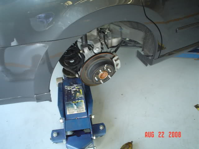
Place adjustable floor jack just under the lower control arm to where it rests with just a little pressure to keep it inplace
Remove nut & bolt
Lower floor jack until completely out of the way (The spring will NOT shoot out as you lower jack)
Push down on lower control arm & remove the OE spring
Use the OE “lower” bushing with new Eibach spring
Install new spring with lower OE bushing ensuring you line up the bottom of the spring with the ‘stop’ in the lower control arm.
Raise arm back into place
Put nut & bolt back in place
Once back in place & secured, remove floor jack & proceed to other side.
FRONT END: 2-3 hours depending on experience
TOOLS NEEDED: Air ratchet or air gun, 17mm socket, 3/4″ open wrench
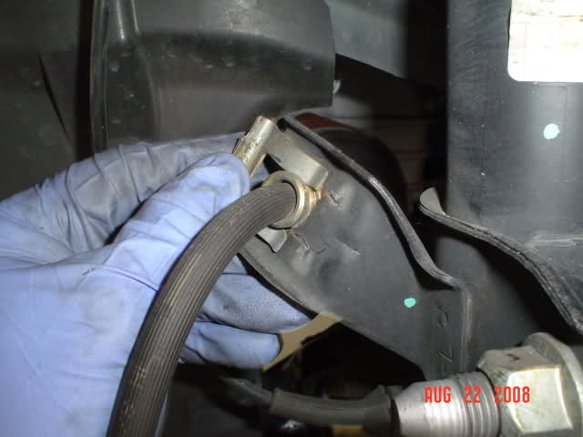
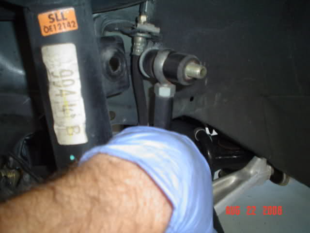
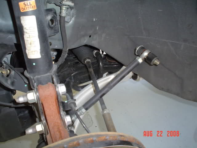
You have 2 bolts that hold the brake in, 1 bolt for your upper control arm, your brake hose ‘clip’ & 2 small rubber grommets
Remove all of these parts (bolts, nuts, grommets, etc)
Then go into the engine bay & remove the 3 bolts (14mm I think) that hold your strut in place. If you have a FSTB, you’ll have to remove this also. Do one side at a time!
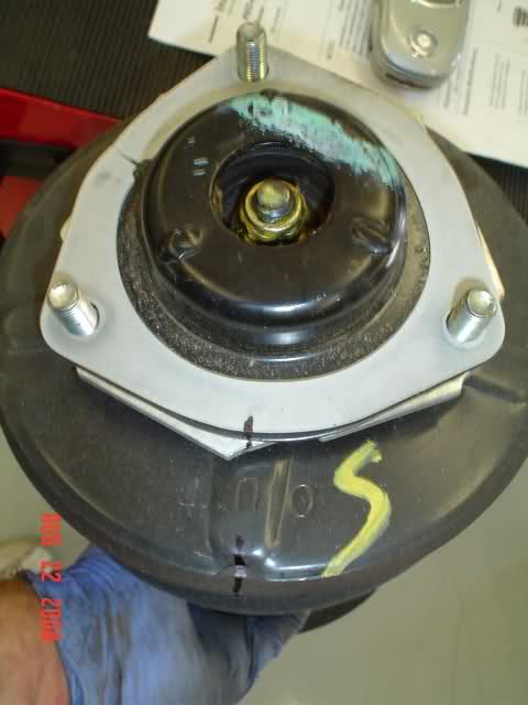
6. Remember how your strut arm looks when you pull it out. It’s best to mark each item with a straight line using a permanent marker as shown below after you remove it.
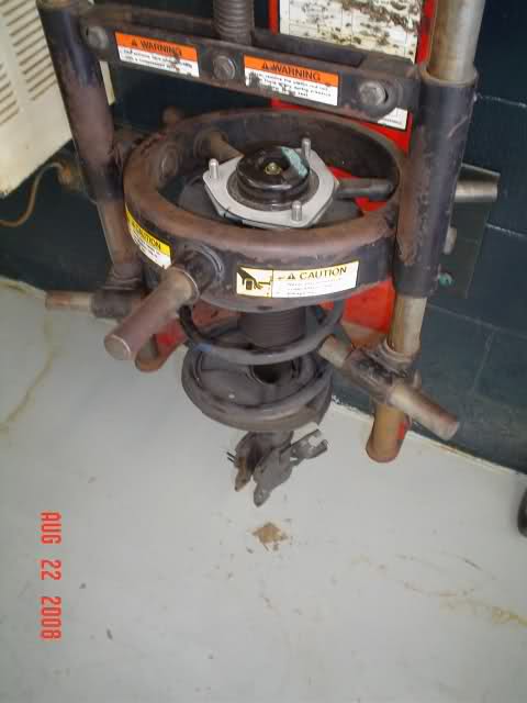
7. Now take it to the spring compressor & compress the spring.
8. Tighten the spring down in the compressor, unbolt the top bolt & remove everything.
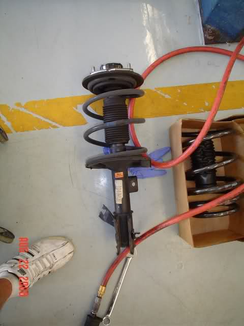
9. Be sure you install the new bushing and dust cover before you compress the spring back together.
10. Line up the new springs in the coil & compress it just enough to place the bolt back on.
Before:
After:
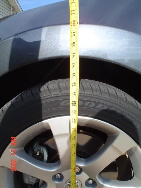
11. Before front drop: 29″
12. After front drop: 27″
13. Before rear drop: 27 5/8″
14. After rear drop: 27″
Why is it important to have wheels properly torqued?
Overtorquing wheels can damage alloy wheels, snap lugs, and can also make it very difficult to remove a wheel with the standard Maxima tire wrench should you have a flat in the middle of the night in the middle of nowhere.
Unevenly torqued wheels can easily result in damage to brake rotors. Undertorqued wheels can result in your having to pay for the cow killed by your wheel as it zips across the meadow.
WHEN?
As soon as convenient after taking delivery of your Maxima, and after every instance when anyone has removed any wheel for whatever purpose (such as tire rotation or brake work/adjustment). Nissan also recommends that the wheels on a new Maxima should be retorqued at around 600 miles. If you did not do this, but the wheels have not yet been off your Maxima, please consider doing it soon..
AMOUNT?
As folks who work on your car are generally only concerned with making sure your wheels don’t fall off, the universal trend is to overtorque. Partially in view of the same concern, manufacturers tend to overstate the amount of torque needed for cars. Here is an example: 70 foot pounds of torque would easily be sufficient for the 6th gen Maxima. ‘Erring’ on the cautious side, Nissan recommends 80 foot pounds. My ’04 SL was actually delivered with from 87 to 96 foot pounds on every lug nut.
I have kept my wheels torqued at 75 foot pounds for over a decade. My son has used 70 foot pounds on all his vehicles for almost twenty years. Less venturesome souls should still torque to no more than Nissan specs (80 foot pounds).
WHICH TORQUE WRENCH?
Ignore the ‘flex’ wrenches; they are not accurate. Stick to ratchet (click) wrenches. Ignore the ‘inch pound’ wrenches; they are not for wheels. Stick with ‘foot pound’ wrenches. It may be possible to torque Maxima wheels with a 3/8″ drive torque wrench, but I would never torque wheels with anything but a 1/2″ drive wrench.
Torque wrenches are sensitive instruments, and should not be abused. They are one of the few tools Craftsman will not back with a lifetime warranty; they cover them for only one year. But with proper care, and an occasional recalibration, they should last decades.
I use Craftsman (Sears), but others such as Kobalt (Lowes) and Rigid/Husky (Home Depot) are probably comparable. Expect to pay from $60 to $80 for a top grade wrench, unless you have a coupon or hit a sale.
SETTING THE TORQUE WRENCH
Read the directions accompanying the wrench very carefully. Not all wrenches are alike. One common setting method is to twist the grip until the cursor is on the ‘tens’ marker (such as 70 or 80 or 90) at or below your desired setting. Then twist the ‘fine selector’ collar until the exact pound you want is centered on the scale.
For 75 foot pounds, we turn the grip until the cursor reaches 70, then turn the ‘fine selector’ collar until its cursor reads 5.
For 80 foot pounds, we turn the grip until the cursor reaches 80, then set the ‘fine selector’ collar to 0.
Once we have the desired foot pounds set, we must turn the ‘locking collar’, else the setting will not hold during use of the wrench.
SOCKET?
Use ONLY DEEP SET (LONG) socket, otherwise an extension is needed. Unless you are fumbling with a 3/8″ drive torque wrench (a no-no), the socket must be 1/2″ drive. The OEM lug nuts on ALL 6th gen Maximas are 13/16ths”. Although a 6 point socket (6 coves inside opening) is preferable for wheel work, most deep set sockets come with 12 points, and these work fine for torqueing.
Many Nissan dealers put one locking lug nut on each wheel. For reasons that escape me, the coded socket furnished to turn these locking lug nuts has a drive end that requires a socket slightly larger than the 13/16th” of the regular lug nuts. I bypass this problem by using a 21mm deep set metric socket, which works well with both the 13/16ths lug nuts and the drive of the locking lug nut socket. If we carefully measure the tire tool that comes with the Maxima, we find it is actually 21mm, not 13/16th”. Just another Nissan quirk . . .
TORQUEING WHILE MOUNTING WHEELS
Mount wheel onto hub. Hand-tighten all lug nuts. Use Maxima OEM tire wrench (the torque wrench may also be used for this) to VERY LIGHTLY snug the lug nuts.
Lower the car until the tire has good contact with the ground/floor. Torque each lug nut to specs (Nissan says 80 foot pounds, I use 75). IT IS IMPORTANT (for the wheel, rotor, etc) to torque the lug nuts in one of these two ‘across-the-hub’ orders: 1-3-5-2-4 or 1-4-2-5-3. Either of these orders may be used in either a clockwise or counterclockwise direction. In order to keep things simple, I always consider the lug nut nearest the valve stem as #1, and number clockwise.
When using the torque wrench, apply a steady pressure, using only the grip, and being alert for the ‘click’ and sudden slight slippage that tells us the appropriate torque has been reached. Release pressure on the wrench immediately, as further pressure takes the torque past the desired setting. Never slip a pipe or other ‘extender’ over the handle to ‘make things easier’.
Starting the torquing with the handle at the ‘4 oclock’ position works best for me. That enables the pressure to be applied in a natural downward direction, and reduces chances of damage to the car if anything slips.
ADJUSTING TORQUE FOR WHEELS ALREADY MOUNTED
Read the last two paragraphs in the preceeding proceedure (Torqueing While Mounting Wheels). Car should be setting on ground/floor, which does not have to be level. Using the Maxima OEM tire tool (or other suitable wrench or breaker bar), loosen a lug nut slightly. Torque that nut to the desired foot pound setting. Proceed to the next lug nut.
In this procedure, it is not necessary to follow the ‘across-the-hub’ torqueing order given above for mounting wheels, although I still use it from habit.
I’ve seen plenty of 6th gen brake swaps into 4th/5th gens but I’ve never seen them modified to clear 16in rims.
I have 16s, spring and stuts, I plow through potholes in NYC, I’m never going to drive low and SLOW and avoid all potholes like some others with huge rims and lowered cars. With that being said, I needed bigger brakes to help me SLOW down better.
I already had 11″ 2000 Max rotors and 4 piston wilwood dynalite calipers.
good for 60-0mph stops, but doesn’t fare too well with repeated high speed braking (100mph+)
so back to the drawing board I went – The result is this thread
old brake setup: 2000 Maxima(thicker than 95-99) 11″ rotor with dynalite 4-piston wilwoods
they clear 15s with no problem!
OLD setup vs New (11″ rotor vs 12.6″ rotor)
Here’s where the fun begins:
To put 6th gen brakes into a 4th gen you need to enlarge the caliper mounting holes on the spindles.
Stock is 12mm
Need to enlarge holes to 14mm
So I got spare spindles, drilled them out, replaced wheel bearings, and cut off the heat/splash shields to clear bigger rotor.
I mounted the 6gen rotor and caliper to spindle with a wheel spacer to hold it in and test the fitment on 16s.
It didn’t fit so time to bring out the grinder!
I grinded off the following parts of the caliper:
and then grinded some more and some more..
and then test fit it
and got it down to this
once it cleared without issues I painted them
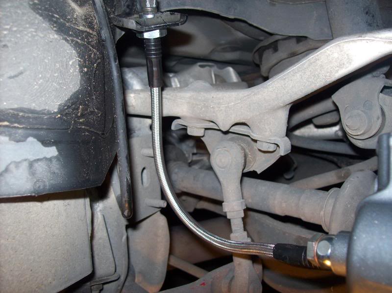
old SS brake lines were all nasty and weathered so: New Goodridge SS brake lines
I did not need to use wheel spacers – they fit under the rims
SO TIIIIIIIIIGHT!!! I love it!!!
Braking is greatly improved. Had this setup since the end of summer and no rubbing, no issues just good brakes.
How do they compare to the Wilwood’s?
The wilwood’s did have a better initial bite (4 piston clamp vs 1 piston) but when you step on the 6thgens they just hold and hold like no tomorrow. Wilwood’s would hold until a certain point and then start slipping (rotors gets hot)
For a typical drive around there’s no difference in braking 50-0, but when you push the car hard repeatedly, or braking from high speeds – they perform very well.
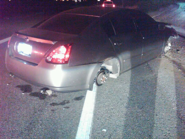
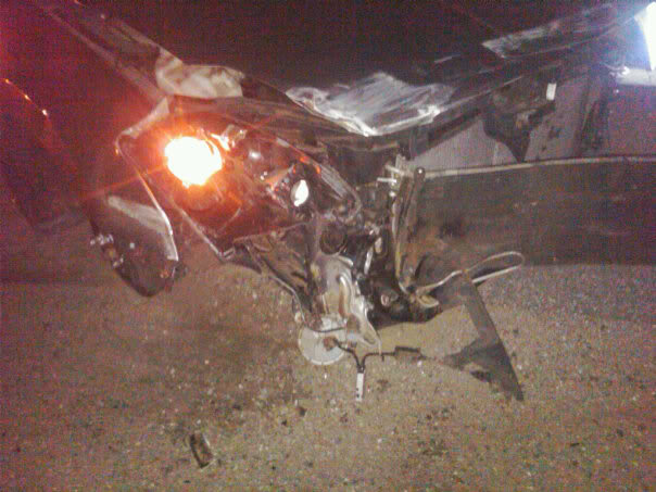
Ok guys after seeing pictures of a 6thgen totaled because they didn’t have OEM G37s wheel lugs…. I’ve decided to make this thread hoping that it never happens to anyone. It almost happened to me but I was quick to get it to place the broken studs and get G37s OEM wheel lugs.
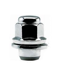
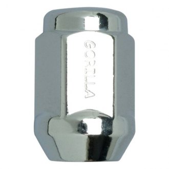
Even if you torque the lugs as much as you can to the extreme…..its pointless because the G37s wheels use a washer type lug. The regular ones will cause the lug hole to expand causing it to break. I know because I have G37s wheels and when I first put them on to drive to home… they got a bit loose.. So please keep that in mind. I would hate to see this happen to anyone else.
Look at the differences below
G37s OEM Lugs
Standard Lugs
This is what can happen if you don’t use G37s Washer Lugs or Equivalent on your 6thgen!!
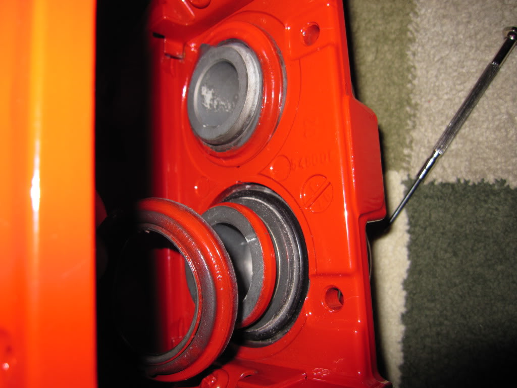
I purchased some use Brembo brakes and had them PC red, I did not know any better and send them to get PC without removing the seals and piston. If I could do it again I would definitely remove everything before getting them PC. I could not find a DIY on G35driver so I decided to create this to help out other members.
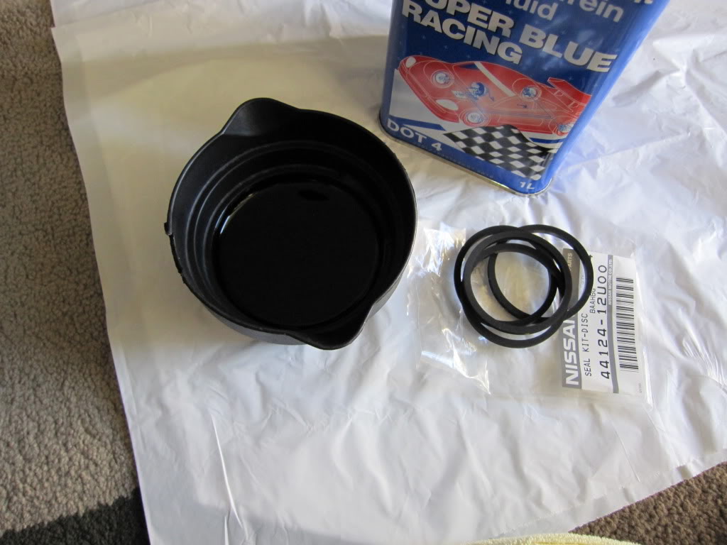
For those that are curious the Brembo Front Calipers Rebuild Kit part # is: 41120-12U25
Rear Calipers Rebuild Kit part # is: 44120-12U25. The kit comes with Brembo seals and O-rings along with bleeder screw caps. I want to thank Rob from Z1 Motorsports for the kit and help.
First remove the clips, pin, spring and brake pads. I didn’t take pictures of this process since there are several DIYs showing how to accomplish these. You should end up with something like this. I would recommend cleaning the hardware
Remove the dust boot. There is a small hole, use a small crew driver to pop it out gently. It should come out really smooth.
Do the same for the rest of the dust boot.
After all the boots have being removed, the next step is to remove the pistons. I took several towels and roll them up and put it in the middle of the calipers to absorb the impact. Then I use my air compressor to put pressure and pop out the pistons. The air should go in the same hole where you connect the brake line.
There are different items that can be use, the most common is a piece of wood. I didn’t have a piece of wood so I use the towels and it worked just fine for me. Just be very careful during this process because the pistons will shot out fast and make a loud pop.
In one of my calipers only one of the pistons came out. I push the one that came out back in and then retry to get them both out at the same time with the air compressor, but again only one came out. I got frustrated after several attempts and improvised by prying it out with two flat head screw driver. If this happens to you I would put tape or something to protect the calipers and pistons. If you put down even force on both screw driver it will slowly come out with not problem.
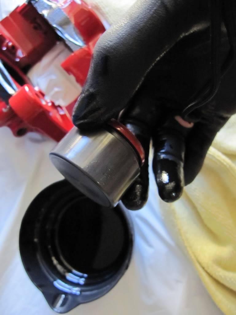
After you get the pistons out, carefully use a small screw driver to pick out the O-ring, it should come out very easily. Not shown in this pic, but clean the inside really good and then lube it with brake fluid.
Let the new seal soak up in brake fluid prior to putting in.
This is how it should look after inserting new seal.
Clean piston then soak it in brakefluid along with the dust boot.
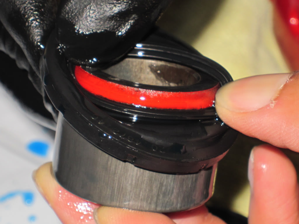
Install new dust boot
Pull down on boot until it catches in the piston groove, like this
Then pull up
Put piston in the hole so it sits straight, not crooked
Push the piston in gently until you feel some resistance .
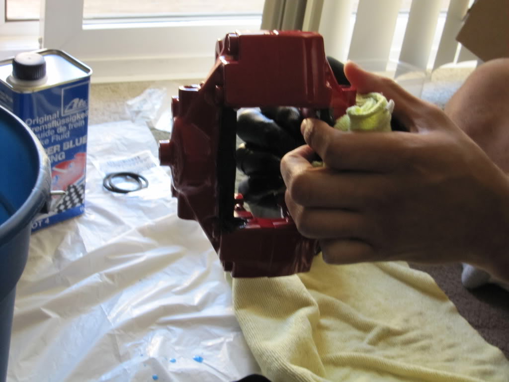
Then hold the caliper as if you are hugging it and push the piston in with your fingers tip
Apply EQUAL pressure with both hands and it will slowly go in, be patient.
You don’t need to use a vice grip, clamps, or other tools. If there’s a lot of reistance, take out the piston, clean it, relube it, and try again
It should look like this went done. Follow the previous steps for all calipers.
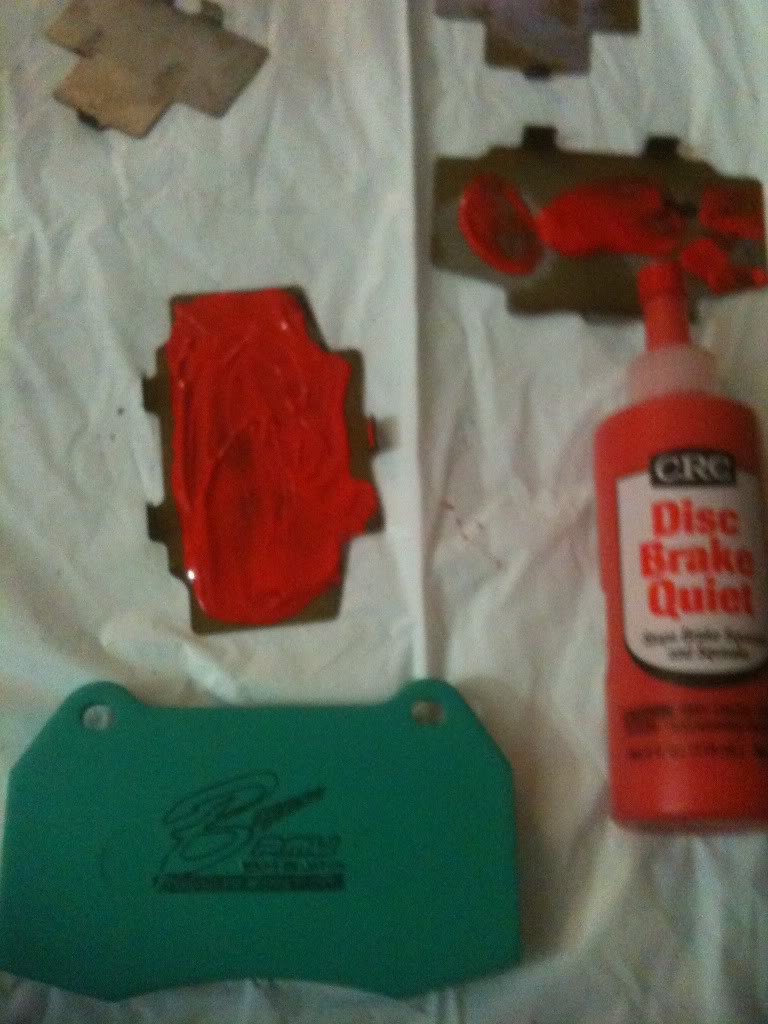
The next steps are for installing brake pads. I purchased Project Mu B-Force pads, heard some good reviews. I put on brake quite to avoid brake noise. The rest of the pictures are really self explanatory.
If any one has any better way to perform any of these tasks please post it. This was my first time ever doing this I learned along the way. Peform at your own risk, I am not liable on anything that goes wrong using this guide.
This write-up is for a 2003/2004. But the same steps are application to 6thgen Maxima. Also, for 7thgens you do not need brackets but the installation instructions still hold.
This DIY will take you through the basic steps to remove the existing brake components (calipers, rotors, lines) in order to install the Akebono brake kit that is standard on the G37S and the 370Z Track model (I think it’s called “Track”..can’t remember).
I wanted to note one more thing, you don’t to completly purge your brake fluid for this installation. I needed to change mine out, it had been a year and a few track events so it was time for replacement. You can simply disconnect the lines and cap them, just make sure to bleed the system when you get everything put back together.
Front Rotors (14″ Stoptech Slotted): 27lbs each ()
Rear Rotors (13.8″ OEM blanks, vented): 18lbs each ()
I will weigh the existing components next week and update this thread to show the delta in both unsprung and rotating mass.
Some tools needed for the install: Floor jack and jack stands. I used stands for the front of the car and my floor jack to raise the rear via the rear differential.
Basic set of sockets, wrenches. A 7/8″ socket was required to remove the bolts on the front caliper.
Tin snips, dremel, cutoff wheel or equivalent to remove/cut dust shields.
Vice grips
10mm open ended wrench (Akebono calliper bleeders)
Flathead screwdriver
Rubber mallet
Bowls and tubing to bleed brake system (I used 1/8” aquarium line)
Onto the install:
Break all lug nuts loose, raise car, remove wheels and set aside. You will have access to the existing rotor and caliper now.
Front rotor/caliper
Rear rotor/caliper
Set up some bowls/cups (whatever works for you) under each caliper and drain brake fluid. Attach the tubing to the bleeder screw and slowly open the screw.
Rear drain setup
Front drain setup
I used the Motive 0107 bleeder to flush the brake system
Be very careful with brake fluid, it is highly corrosive and will eat through your clear coat and paint in a short amount of time.
Front caliper fluid drained
Rear caliper tubing
Rear caliper drained
Do this to all four corners. I started passenger rear, drivers rear, passenger front, then drivers front until all the fluid was evacuated from the system.
I bought stainless steel brake line with my kit, if you are using the OEM lines then ignore the next few steps.
Break loose the two bolts attaching the caliper. I used a 7/8” socket for these. If you have never removed these then it would help to spray some PB Blaster/WD40 on them and let them sit for a while.
Remove the two 12mm bolts securing the OEM lines to the strut.
This is a tricky step, remove the clip that holds the OEM brake line to this bracket. There was quite a bit of dirt and debris in there, I used a small flathead and worked around the clip until it came out. I used a small pair of vice grips to loosen the nut.
Now that the two caliper attach bolts are broken loose and the lines are unhooked, simply slide the caliper off the rotor. You may need to rock it back and forth a few times for it to come loose. Here’s one of the front calipers off the car.
Now it’s time to remove the rotor. You may need to break out the rubber mallet for this one. Nothing like banging loudly on your car at midnight! Rotor removed and off the car.
Now we have a clear shot of the dust shield. You MUST trim or remove the shields to get the new BBK to fit. I initially wanted to remove the shields but they are sandwiched in between the spindle and the main suspension components. I was able to remove 4 of the 5 17mm (I think) bolts, the last one I could not remove. This said, it was time to start hacking as much of the dust shield off as possible! You can get by with trimming a little, but I wanted that thing gone! If dirt or debris gets into the rotor it should be able to find its way out pretty easily.
This is one of the tabs that will get in the way (lower front)
Closeup of dust shield on
Dust shield trimmed to my liking.
Here’s the OEM front rotor next to the Stoptech rotor.
Do this for both front brakes. Now it’s time to go work on the rear brakes!
Again, if you are re-using your existing lines then skip this step. Loosen the nut attaching the flexible brake line to the hard line using a flared wrench or vice grips (same as front, except there are no attachments to the strut….much easier!)
Remove two 19mm bolts attaching the rear caliper to the car. Again, if you have never removed them then let them soak in PB Blaster or WD40. (Sorry, no good pics of this.)
Here’s where you get to bang on the car VERY violently. Make sure you release the parking brake first. The rear rotors seem to get stuck harder than the front rotors. I sprayed around the 5 bolts and hub with PB Blaster and let it sit a few minutes then started hitting it with the mallet. Hit the rotor along the back side, actually the dust shield. Also hit it along the outer perimeter of the rotor. Eventually (after a good 15 minutes for me) the rotor broke loose.
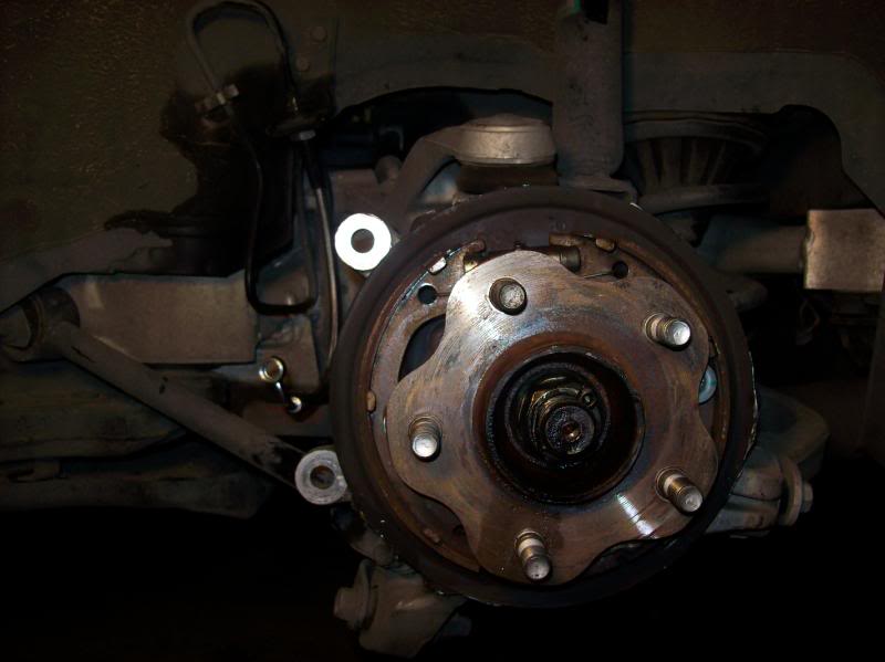
With the rotor removed we can start hacking away at the rear dust shield. The rear dust shield has an out ring that must be trimmed for the new larger rotors to fit. Again, I cut as much of the shield off as I could.
Rear dust shield hacked to pieces!
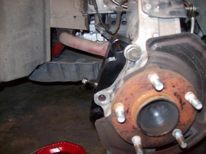
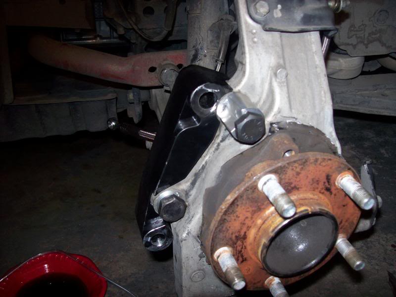
Now it’s time to look at the front brackets to attach the Akebono calipers. Unfortunately there were no instructions on how to install these. I looked at some pics online and it helped a little. The COZ bracket kit comes with four machined parts, two large brackets and two moon shaped pieces. After trying different combo to fit here is what works:
Now, the tricky part of this is to get the moon shaped piece aligned just right…there isn’t much room for error on this. If it is not aligned right then the upper caliper bolt holes will not line up. Here is what I eventually did after a few failures. With the rotor off the car, attach the large bracket as show. Then attach the moon piece, but do not tighten down. Attach the Akebono caliper to the bracket. Now, align the moon spacer so that the upper caliper bolt hole aligns with the caliper bracket and install bolt to secure calipers. Now that the caliper is secure and in place, go ahead and tighten down the moon shaped spacer. Remove the caliper and install the rotor.
Now that the front rotors are on it’s time to build up the calipers. The kit comes with grease, pads, shims, pins, clips, cotter pins….everything you need. I didn’t take pics of
The build up because everyone was asleep and my hands had shim grease all over them. Here’s the front caliper on the car.
The front was a tight fit, hopefully it will loosen up a little after some driving. Now, install the caliper to the adapter bracket.
Attach the new brake lines to the caliper, 14mm bolt. No pics, but it’s pretty much error free.
The rear calipers are much easier to install. Build up the brake pad/shim/clip assembly and put in the caliper. Reuse the existing 17mm bolts to attach the caliper to the car.
Caliper/rotor on car,
Pad build up
Brake line installation
Now that everything is installed it’s now time to refill the system with brake fluid, reinstall the wheels, lower the car and brake in the pads. Make sure to lower the rear of the car first and put some tire chucks behind the tires before you lower the front so the car won’t roll back.
Here’s a few pics of mine installed.
Updates:
So I went for a quick drive around the neighborhood today. The pedal was very squishy and I had to pump the brakes to get adequate pressue to stop the car. Went home and checked all my lines, no leakes. Then I got to looking at the rear calipers. I had them installed with the bleeder screws facing down……BAD IDEA! (this is why you don’t work on cars at 2:00am!). I switched the rear calipers so the bleeder screw was on top, bled the system and drove again. Wow, what a change. The pedal is much more firm than stock. I am going to bed the brakes this afternoon sometime.
If you try to bleed the brakes with the screw at the bottom you will entrap some air in the top of the caliper. Always have the screw at the top so the fluid occupies the bottom of the caliper and fills its way to the top, releasing the air out of the system.