Error: View cc78fc3s3c may not exist






















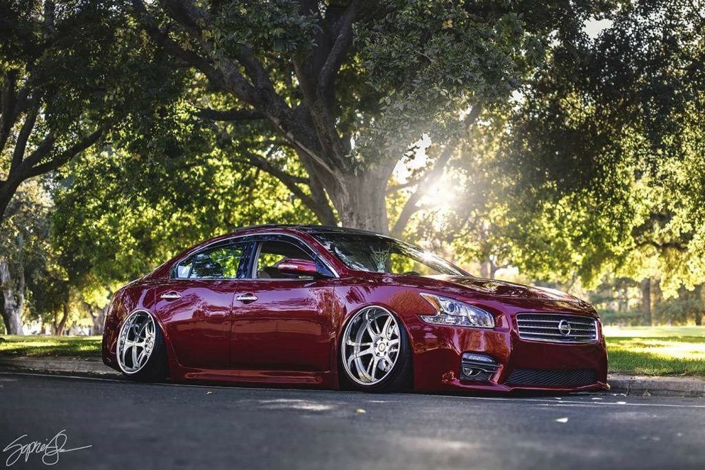


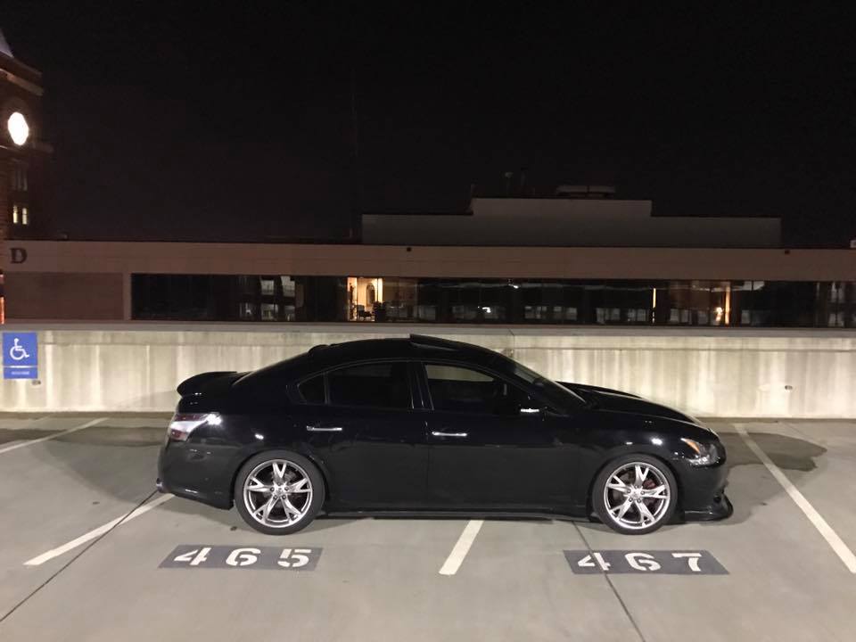

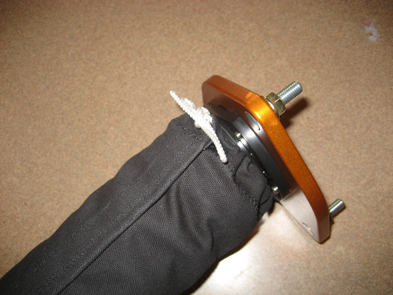
Member Credit: omahasubaru

Materials you will need:
– canvas material from a local fabric store.
– heavy duty thread
– heavy duty velcro
– some rope/string or zip ties
Tools you will need:
– Fabric tape measure
– Scissors
– Pencil or fabric marker
– Sewing machine
Other items that may be useful:
– Spare fabric to use for your first template
– Ability to use this DIY as a guideline and interpret/adjust as needed.
– A measure twice cut once mindset
– Patience
– Skill with the sewing machine, or a friend who does
Phase One : Building a template
There are a few ways to do your covers. I’m only going to cover the two more popular ways.
1) Measure your springs and perches
You’ll want to use the fabric tape measure for this. Measure around the widest part you want to cover. Sometimes this is the upper or lower perch, other times it is spring. Especially if you have some of the newer Hypercoil OBD springs. Take this measurement and add around 1.25-1.5″ to it and write it down. This helps to account for overlap and velcro strip.
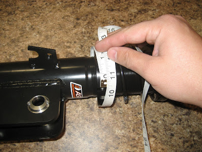
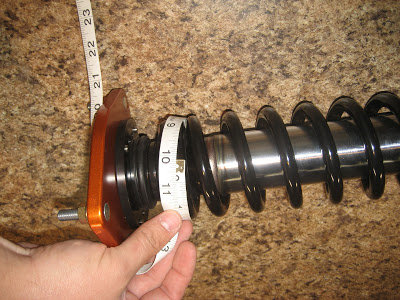
2) Measure your coilovers for the length you want to cover.
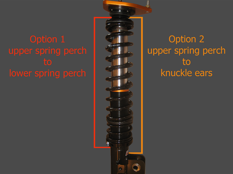
This is where options come in. You can either measure from above the upper perch and just to below your lower spring perch, or you can measure all the way down to the knuckle ears if you want. Neither way is wrong, but I prefer the latter, as it covers any remaining exposed un-used threads you may have. Please be aware that not all struts are the same length. You rears will likely be longer than the front, so you may have to make two patterns for best results. Write down your measurements.
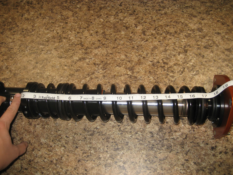
3) Build your template
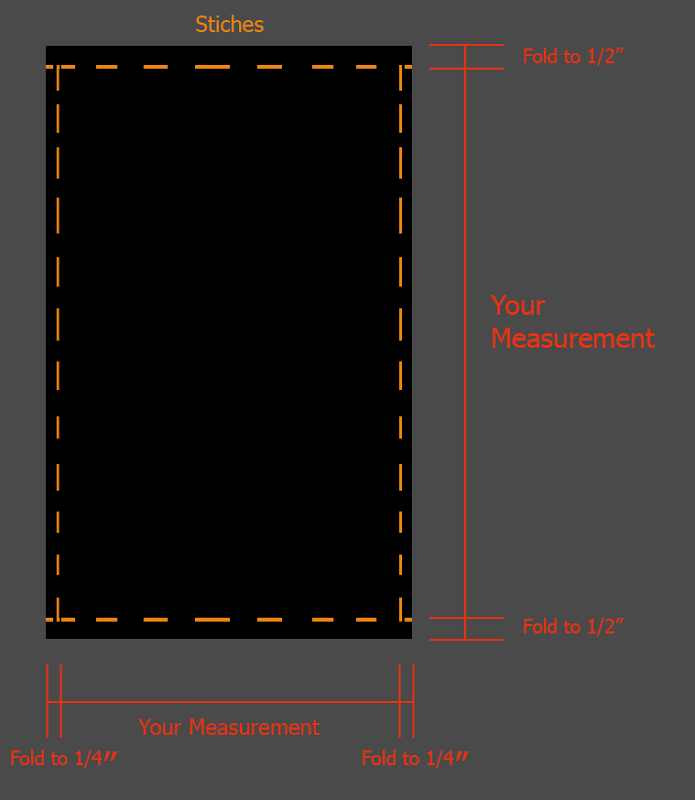
Take your measurements and use the guide here to add to them. You have to add to account for folding over and stitching. This also gives you just a little more length depending on how good your measurements were. Your measurement goes on the inside of the lines in the template below.
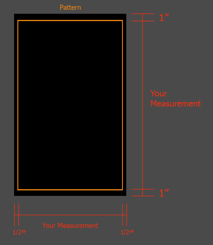
The top/bottom has a longer fold to account for room to run your rope/string or ziptie through to snug up the ends.
4) Test fit it.
It should be over-sized at this point, but this is a great time to catch any issues you may have with your measurements before you go further.
Phase Two : Make your bags
Now we take your cut out pattern and start to put it together.
1) Fold & stitch your pattern.
Use this guide below to setup your folds and location of your stitching. You don’t want to stitch the ends closed as then you can’t run your rope or tie through to snug up the ends. Use the zig-zag stitch pattern on the sewing machine.
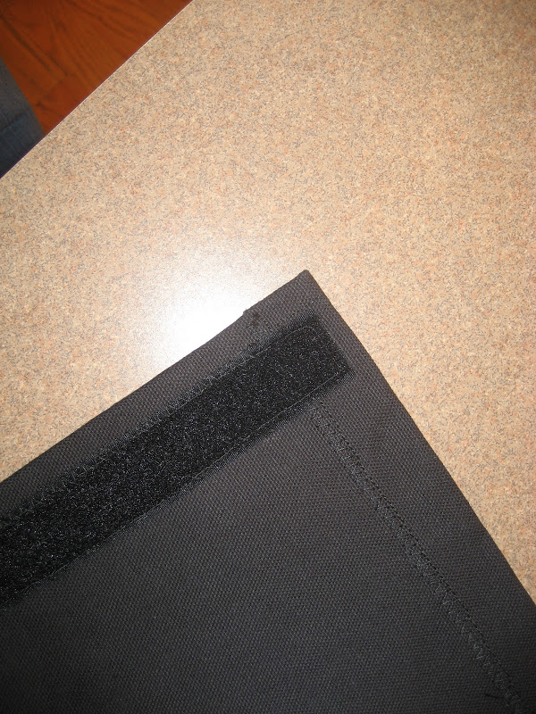
2) Place your velcro & stitch it on.
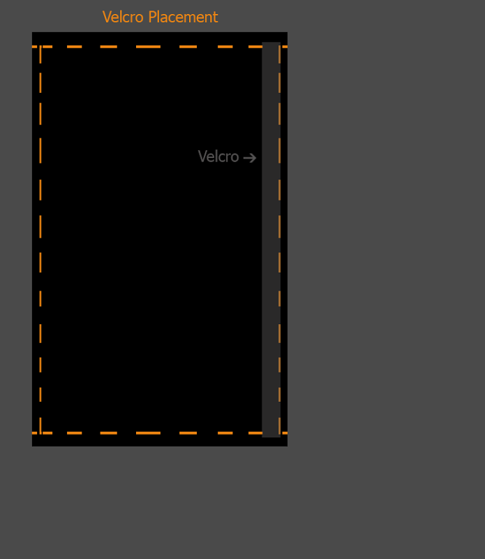
Use the guide below to determine where to locate it. You need to place one side of the velcro on one end and stitch it on. Then place the matching side of the velcro on the other side of the fabric on the opposite end. This is so when you wrap it, the velcro meets up correctly. Use the straight stitch pattern on the sewing machine.
3) Test fit it.
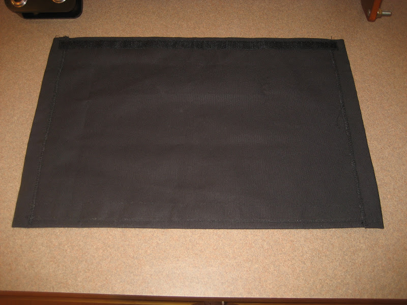
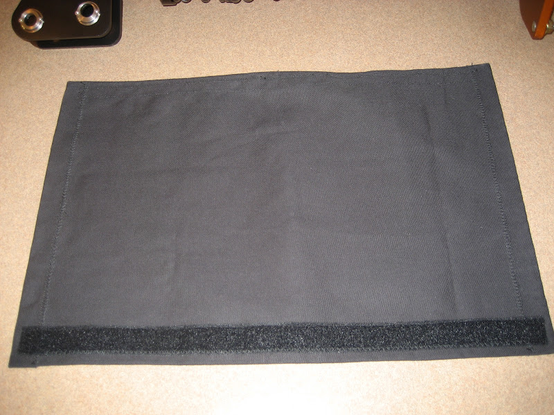
Now it should fit quite well and should look something like this.
4) Choose your snug method.
This is where you decide if you want to use some rope/string material to snug up the ends, or zip ties. I initially went with some nylon rope, but have since had concerns about how well it would stay tied and have elected to go with zipties. My intended use for the car and the [COLOR=blue ! important][COLOR=blue ! important]suspension[/COLOR][/COLOR] is scca rallycross events and lots of gravel road use. So I really didn’t want my bags to sag.
Phase Three : Repeat & Enjoy
Now you merely continue to make your remaining coil bags and then put them to use.
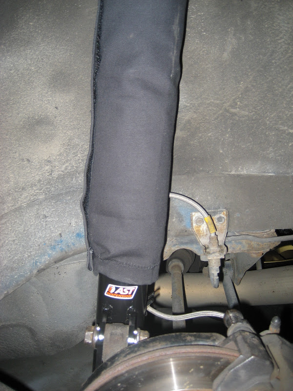
Thanks for checking out my DIY, I hope someone can find it useful.
Member Credit: TC from Zmods
Tools Required:
– Z32 front caliper rebuild kit
– 14MM Socket & ratchet
– Torque wrench
– Bench Vice
– Air Compressor
– Fine tipped awl
– Bench grinder with a wire wheel
– 2 cans of brake cleaner
– Acetone or lacquer thinner
– 2 cans of high temperature paint in the color of your choice
– High temperature clearcoat (optional, but recommended)
– Set of Speed Bleeders (optional, but recommended)
– Set of stainless steel brake lines (optional, but recommended)
– 2 quarts of brake fluid, brand of your preference
!!!WARNING!!! – This task can be a little tricky, so if you don’t think you’re up for the job, DO NOT ATTEMPT THIS!! Brakes are nothing to fool around with if you’re not completely sure of what you’re doing!! A mistake could land you in the hospital or morgue, and your car in the junkyard!! If you have little or no experience with brake work, forget you ever saw this writeup, and let a professional handle this job!!
I also recommend purchasing a set of core calipers off a parts car to do this on, as this procedure is time consuming. It will take a few days to do it right and allow the paint to cure, in which time your car will be out of commission, which is not an option if your Z is a daily driver. Its a lot easier to do this to some spare/core calipers, that way the brake lines aren’t left open very long, and you can still drive your car while working on this. This is also a perfect time to upgrade from the scrawny 26mm calipers if you have an early 1990 model NA. When you’re finished, you can resell your original calipers and recoup your money spent on the rebuilder set you bought.
With the above out of the way, now the fun begins!!
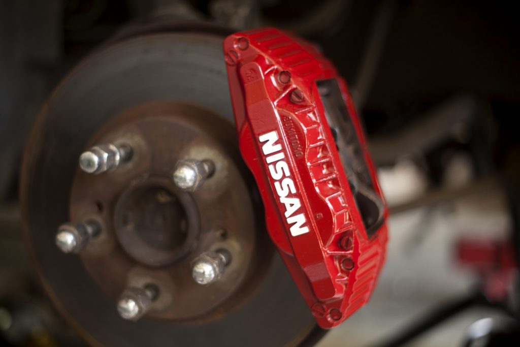
These are a set of 30mm aluminum calipers I pulled off a 1991 Twin Turbo parts car. They were high mileage, and had definitely seen better days…..until now!!


Basic Preparation for the build
Step 1:
The first thing you want to do is remove the pads and all the pad retention hardware. If you’re reusing your old pads and not replacing them with new ones, you need to mark their orientation!! This is VERY important!! They need to go back on in the same location they came off!
Step 2:
Now that the pads and their hardware is out of the way, you now want to remove the rubber dust boots and retainer rings from the caliper pistons. Use the fine tipped awl and simply pop the metal ring off. The boot may come off with it. If it doesn’t, just grab hold of it and pull, it will come off easily. You may discard these items in the trash FOR THE FRONT BRAKES ONLY, they will not be reused. The rebuild kit contains new replacements for the front brakes. You MUST SAVE the dust boots and O rings for the rear calipers!! Be VERY careful not to puncture the dust boots with the awl during removal on your rear calipers!!! The rear rebuild kits are NLA (no longer available) from Nissan!! On this note, they VERY VERY rarely ever fail, so this is nothing to worry about, you can reuse the O rings and dust boots without fear! When you remove the O rings and dust boots from the rear calipers, simply inspect them for damage. Damage you want to look for will be torn dust boots or damaged O rings (signs of leakage, cracks or chunks missing). It’s not likely you’ll find any. If for some reason you do, you’ll need to replace that caliper.
Removing the pistons
The pistons now need to be removed from the caliper. This next sequence can be a bit tricky, especially if you have a sticky piston. A stuck piston is not too common, but it can happen. The pistons should come out fairly easily with the aid of an air compressor. If the piston is seized, the caliper may need to be replaced.
Step 1a:
Place a 2X4 up the middle of the caliper, between the pistons. Then place your air hose with a small nozzle chuck attached over the line fitting on the back of the caliper. Make sure the bleeder valve is installed and tight. Get yourself into position, making sure your fingers are NOWHERE NEAR the pistons!!! When you shoot the air into the caliper, the pistons will come out with some velocity! If your fingers are in the way, it can definitely cause injury!! When in position, give it a shot of air. The pistons will start to come out and converge on the 2X4. If any one comes completely out, leaving other still seated, slide it back in just enough to reseal, and shim the opposite side of it with thin wooden shims to keep it in its cylinder, allowing the others to come out.


Step 1b:
On the rear calipers, use the same technique, just use a thinner piece of wood. I used a piece of 3/4″ plywood, it worked fine.
Step 2:
Once all the pistons are protruding from the caliper like the ones on the left in the picture above, they should pop out with little effort. If they’re still too tight to pull by hand, you may use some large pliers. If you need to use pliers, grab the outer lip that the dust seal rests in!!!! DO NOT GRAB THE PISTON SIDES!! If you scratch or score it, the piston is ruined, as this will cause leaks!!
Step 3:
Now that all the pistons are out, you want to remove the “O” rings from the cylinders. Use your awl and carefully slide it between the ring and the slot, and raise up on the O ring. BE VERY CAREFUL NOT TO DIG INTO OR SCRATCH THE O-RING SEAT!! Again, this will cause irreparable damage, resulting in a leaky caliper!! When you’re all done, this is what you should have:

In this sequence, we will be splitting the two caliper halves apart.
Step 1:
Place the caliper in your bench vise, and snug it down.
Step 2:
Using a 14MM socket & ratchet, loosen all 4 of the bolts. Once all 4 are loosened, go ahead and remove them from the caliper. Make sure you have a hold of the caliper half that’s not in the vise, as when the bolts are removed, it may fall.

Step 3:
Separate the halves, paying VERY close attention to two small O rings between the halves!!! They may fall to the floor or stick to the caliper. DO NOT LOSE THESE!! The kit does NOT include replacements for them, so these need to be kept safe for reuse during reassembly!!


Ok, this sequence is chemical washing of the caliper. This is where those cans of brake cleaner will be used. I did this outside, as it can be messy.
Step 1:
You want to douche (< heh) the caliper halves VERY thoroughly!! Make sure you get the fluid journals and the cylinders clean of all fluid and dirt, same with the exterior. I recommend wearing rubber gloves when doing this, as the brake cleaner can irritate your skin, and you WILL get some on your hands!! I have tough skin when it comes to things like this, and I’ll admit, this stuff bothered me.
Step 2:
Let them dry, it won’t take long, the cleaner evaporates fast. When done, they should look similar to this:


This sequence is also another self explanatory one. You want to wire wheel all the embedded and caked on brake dust off. I strongly recommend wearing a respirator or dust mask when doing this!! Brake dust is contains asbestos. Not something you want to be inhaling!
Step 1:
Run the wire wheel over all accessible surfaces of the halves. You want to get into all the crevices, removing as much of the dust as you can. DO NOT allow the wire wheel to get into the cylinders!!! Also, do not wheel the mating surfaces where the halves join. Make sure the O ring seats are clean and free of debris, but don’t wire wheel them if you can help it!!
Step 2:
Wire wheel the pad retention hardware and the 4 bolts as well. On the bolts, make sure you wheel off any rust or corrosion on them. Make sure you get all the crud and brake dust off the bolt heads, or this may cause problems later with the paint.


In this sequence, you want to mask off things that you don’t want paint in.
Step 1:
Mask off all of the cylinders, including the outer lips.
Step 2:
Place a small piece of masking tape over the front and back of the bolt holes. You don’t want paint in the threads.
Step 3:
Place something in the line hole. I used an old bleeder I had. If you use a bleeder, you’ll have to first grind the tip off it to allow it to fit. Also, make sure it’s free of any oil or brake fluid.


Step 4:
You now want to take a rag and wet it good with acetone or lacquer thinner. Wipe down the whole caliper with the soaked rag. This will remove any residual contaminants you may have gotten on the caliper from handling it after the chemical cleaning and the wire wheel cleaning. After wiping it down thoroughly, do not touch it with your bare hands again!! This is the final paint prep step before you actually spray them. If you get oil from your skin on them, the paint may not stick in those places.
Step 5:
Rig hangers to hold the calipers for painting. Do not set them on flat surfaces, you won’t be able to get the underside, and it will definitely show in the end!! When making your hangers, set them so you have 360 degree access around them, so you can coat them evenly.


Painting your calipers
This is it!! This sequence covers spraying the base coat on the calipers. I used Duplicolor’s high temp flat black as a base coat. This paint requires no primer, and can withstand temperatures up to 1200 degrees!
Step 1:
Follow the directions on the paint can, as that’s the best way to start. Lightly coat the calipers the first couple coats, letting it tack up for a few minutes between coats.

Step 2:
After two or three thin coats have been applied, start making the coats thicker. I typically use five or six coats of base on a caliper, this makes for a smooth yet robust coating. 2~3 thin coats, and 2~3 thicker coats. After your last coat, your calipers will look something like this (Yes, that is black. The paint is wet, and the flash distorts it a little. This is normal):


Step 3:
Allow the calipers to hang and dry for 24 hours.
Blocking the raised letters
This sequence will remove the paint from the raised letters, If you want the letters the same color as the calipers, you may skip this sequence.
Step 1:
You’ll need a sheet of 100 grit sandpaper and a sanding block. I used a scrap piece of a 3/4″ plywood with a flat surface. It was the perfect width to cover the lettering, but not overlap the rest of the caliper too much. This is helpful for avoiding acidents.


Step 2:
Wrap a small piece of the sandpaper around the block, making sure its pulled snug, so the paper won’t slip.

Step 3a:
Sand the lettering side to side until all the paint and texture is gone. You’re finished when you’ve got a sharp and clean brushed look.


This is done similar to the paint process. I used Duplicolor wheel clear, which is high temp.
Step 1:
Apply several thin coats, allowing it to tack up between coats.
Step 2:
Apply several thicker coats, again, allowing it to tack between coats. If when applying the thicker coats, using the Duplicolor wheel clear, you may notice a white milky appearance in the coating. This is nothing to be alarmed about, it will clear up as the coating begins to cure.


Step 3:
Allow them to dry overnight before handing them. I recommend letting them sit a couple days before reinstalling, to insure it’s thoroughly dried.
Step 4:
After they’re dried, remove all the tape, old bleeder valve, and whatever you had covering the brake line opening.
Reassembly
This one is also very cut and dry. Simply reassemble everything the opposite of how you took it apart, which is outlined earlier in the writeup.
Step 1:
Clean the pistons thoroughly, removing fluid, dirt, and gunk. Just use a rag and give them a good wipe down.
Step 2a – Front caliper O ring reinstall:
The new O rings will have grease on them. Do not wipe this off! Slide the O ring into its seat, making sure that its in there uniform. They will twist up easily, so make sure it doesn’t do that. You’ll know it if it does, you’ll never get the piston back in!
Step 2b – Rear caliper O ring reinstall:
Since these are the old ones being reused, wipe them down to clean any dirt and fluid off of them. In your rebuild kit for the front calipers, you’ll notice a packet of brake grease. Use a little of this on the O rings to slick them up, and then reinstall them the same way outlined in step 2a.
Step 3:
Now it’s time to reinstall the pistons. Use a little of the pink brake grease and lube the side of the piston. Start the piston into the cylinder, and slowly push it in. DO NOT PUSH THE PISTON ALL THE WAY IN!!!!!!!!!!! You need to leave them sticking out a little to reinstall the dust boot. If they’re all the way back, its a pain to get the boot on!!
Step 4a – Reinstalling the dust boot:
Now put the dust boots on. On the rear calipers, you might want to clean them up with some brake cleaner first, to get the gunk off them. Place it over the piston, allowing the boot to seat itself in the groove on the piston. NOW, you can push the piston all the way back in!
Step 4b – Reinstalling the dust boot:
Once the piston is all the way back, massage the outer edge of the boot until you feel it slide over the lip on the cylinder and seat. Then take the retainer rings and put those back on. Simply pull the ring open at its seam, place it into the groove on the dust boot, and let go. it will snap right into place. Verify it is seated by looking at it all the way around.
Step 5:
Install your new speed bleeders if you elected for those, and tighten them down.
That’s it!!! You’re now ready to reinstall them on the car, and bleed them down! I hope you found this article useful!
Member Credit: shift_ice
Over time the brake system can take on air as the effectiveness of the brake fluid decreases with age. Air can also enter the system from a leaky brake hose, a bad connection on the brake caliper, during any maintenance when a brake line is removed, or if the fluid reservoir is allowed to run dry.
Air in the line makes the brake pedal feel mushy, and bleeding the brakes is the solution to that embarrassing mushy pedal feel. While we’re on the topic, if you’re not happy with the factory brake feel even after the system is properly bled, replacing the factory brake lines with more sturdy steel braided lines can greatly increase pedal firmness and brake feel.
Ttools/Supplies:
INSTRUCTIONS:
1. Place the car on level ground, chuck the rear wheels, and make sure car in park (or in gear if a manual). Make sure parking brake ISN’T on. If you have ABS, remove the ABS fuse.
2. Pump the brakes multiple times to release any residual vacuum in the lines.
3. Remove the brake fluid reservoir cap and fill the reservoir with fresh brake fluid. Check this level often as you bleed the brakes. Never let it get too low because if it gets empty it introduces air back into the brake system and you have to start all over!
1. Passenger rear
2. Driver front
3. Driver rear
4. Passenger front
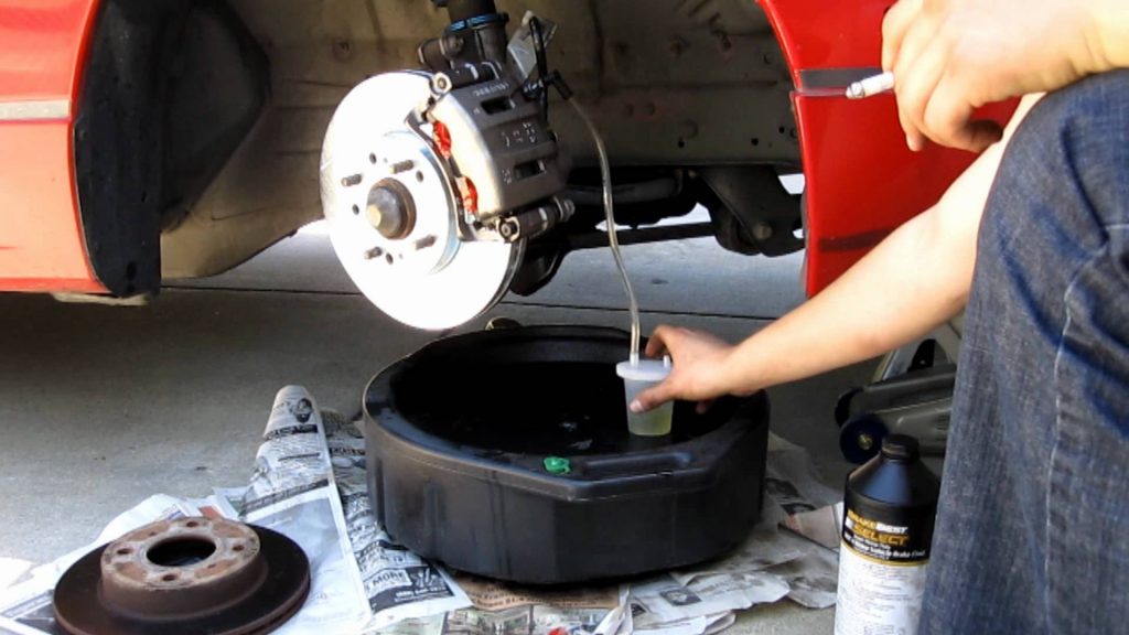
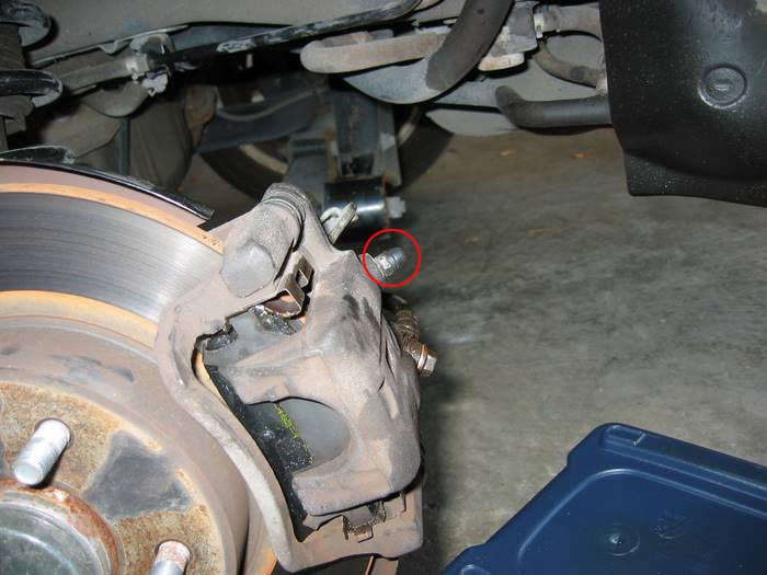
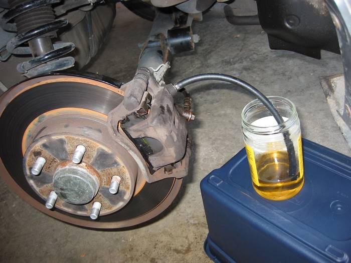
4. Remove the rubber boot on top of the bleeder screw. Attach a hose to the bleed screw and insert the end of the hose into a clear jar that is partially filled with brake fluid.
The bleed screw with the rubber boot still on:
Bleed screw
Hose attached to bleed screw:
Hose attached to caliper bleeder screw
5. Have your girlfriend press firmly on the brake (you’re killing time reading this on the internet so you obviously have one…right?). While the brake is depressed, loosen the bleed screw. If your girlfriend freaks out at this point because the pedal just fell to the floor, throw an empty beer can at her and tell her to quiet down. Or, if you’re not much for the single life, you can be the nice guy. “Honey, that it is completely normal. I just loosened the bleeder screw which allows the brake pressure to escape…oh, and I sure like those new strappy shoes of yours.” Totally your call on this one.
Anyway, back on topic. When you loosen the bleed screw with the brake depressed, you will see brake fluid flow through the hose and into the jar. Watch the tip of the hose for air bubbles – this is a sign that air is in the system. When the flow of fluid stops, tighten the bleed screw and tell your girlfriend (assuming she’s still there) to release the brake. Repeat this process (press brake, loosen bleeder, check for bubbles, close bleeder, release brake) until there are no air bubbles released, only fluid.
If you mouthed off above and lost your assistant, don’t worry, this step can also be done alone if you buy a set of speed bleeders.
6. Check the brake fluid level in the reservoir and top off as needed. Take care not to overfill or spill because brake fluid is very hard on paint. As mentioned above, never let the reservoir get empty or it will introduce air into the system and you’ll have to start over. And let’s be honest, this job is barely enough fun to do once.
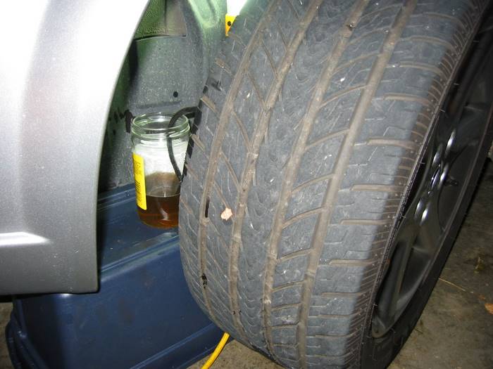
7. Repeat steps 4 -6 at each wheel in the order outlined above. For the front brakes, if you’re feeling lazy you can get away with not removing the wheels at all by turning the tires toward the brake you want to work on. It takes a skinny arm or a strange angle to get a wrench on the bleed screw, but it can be done.
A lazy man bleeding the front brake:
Bleeding the front brakes with the wheels on
8. When complete, do yourself a favor and double check that every bleed screw is tight. Remember, a loose bleed screw means no brake pressure and brake fluid spraying everywhere like a garden hose. And hey, that’s no fun. Well, unless you’re the lucky onlooker.
Member Credit: shift_ice
The following how-to swaps out the factory struts and springs for Tokico Illumina struts (Part # BB3188 Front, BU2943 Rear) and Progress springs, but is generic enough to describe installation of a variety of springs/struts on the 5th gen Nissan Maxima. The install is time consuming, but can be performed at home when equipped with the proper tools in 4-6 hours.
While not required, I recommend asking a buddy to help. It will really cut down on the install time – particularly when compressing the springs.
Tools:
1. Raise both sides of the front of the vehicle using jack and jack stands or hydraulic lift. NOTE: Struts can’t be removed with only one side raised.
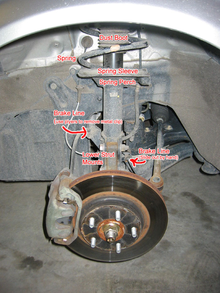
2. Remove wheel with lug wrench. Once the wheel is removed, you’ll see the strut assembly:
Note – The part labeled “Spring Sleeve” is also known as the spring isolator
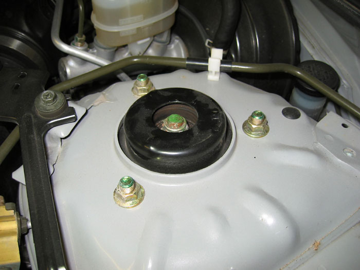
3. Remove the three bolts around the center bolt. Loosen BUT DO NOT REMOVE center nut at top of strut.
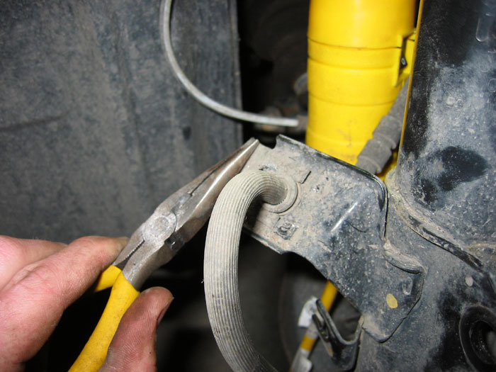
4. Remove the brake line attachments on the struts. Slide the retainer clip on the left out with pliars The other break line attachment can be slid out by hand.
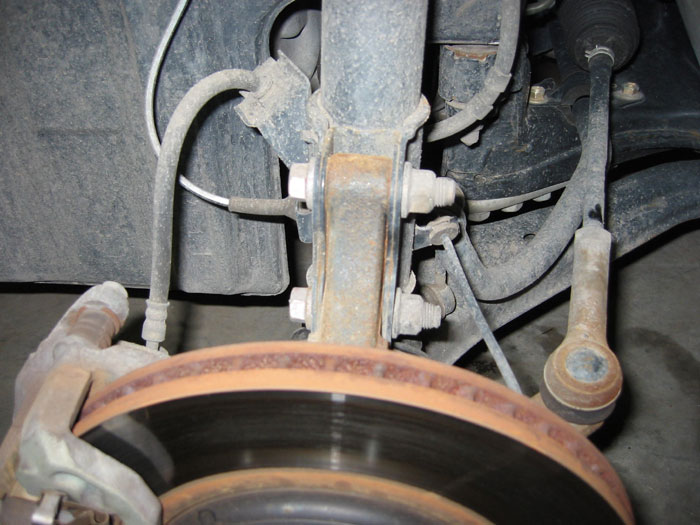
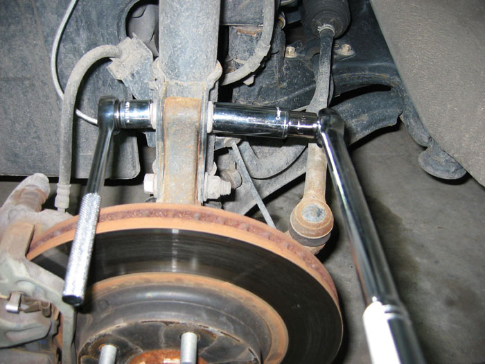
5. Use 17mm & 19mm socket wrenches to remove the two large bolts mounting the strut to the trailing arm. This requires two sockets or wrenches since the bolt on the opposite side will just spin otherwise. The strut will fall when these bolts are removed so be sure to catch it.
NOTE: There is a CV boot underneath the strut where the strut will naturally hit when it’s removed. Be sure to catch the strut when the bolts are removed to avoid damage to the CV boot below. If you really want to be safe, you can wrap your CV boot in a towel to protect it – just don’t forget to remove it when you’re done!
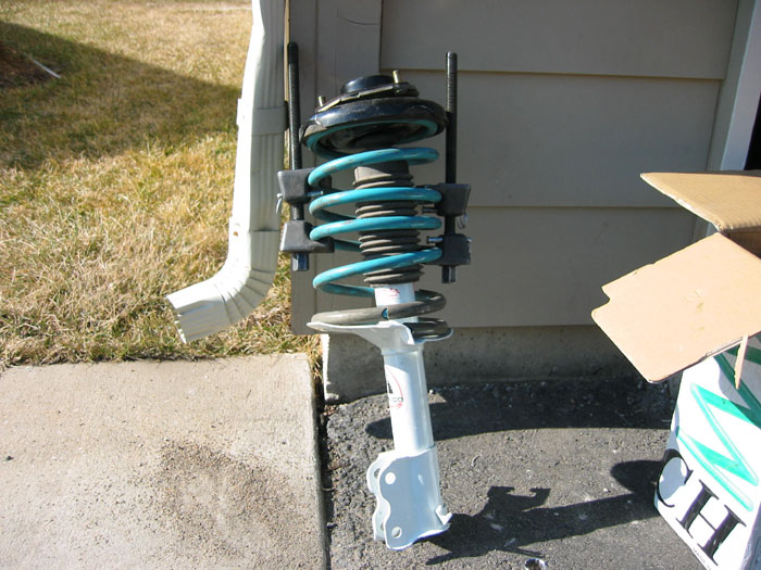
6. With the strut now off of the car, compress the stock spring. Make sure to compress both sides evenly – Don’t tighten down one side and then move to the other. WARNING: Compressed springs can kill. Always point the top of the strut away from you and other people and make sure spring compressor is securely fastened. Take turns slowly tightening each side until the spring is compressed enough to take the pressure off the top hat.
A few tips:
A wrench may be necessary if clearance for the socket is an issue. Or, if you have a second wrench or socket, tightening the compressor on the other side and it should loosen up the socket that’s stuck.
Try to position the compressor as close to the bottom of the spring as possible with the bolts on the compressor facing down toward the perch to avoid clearance issues with the nut on the compressor.
Don’t flip the compressors around where the bolts point toward the bottom of the spring perch – then you’ll have problems positioning the top hat properly since the long bolts on the compressor will get in the way. (Yes, the picture at the right shows the spring compressor oriented the wrong way, but do as I say, not as I do!)
Be sure to skip a coil when installing the spring compressor. Otherwise you’ll have difficulties getting the spring compressed enough. (again, not depicted in the image at the right, but I learned.)
Compressing and uncompressing the springs is a slow process. To speed things up I recommend using an impact wrench or high power drill with a socket bit and socket, u-joint and extension so the spring compressor can be tightened quickly.
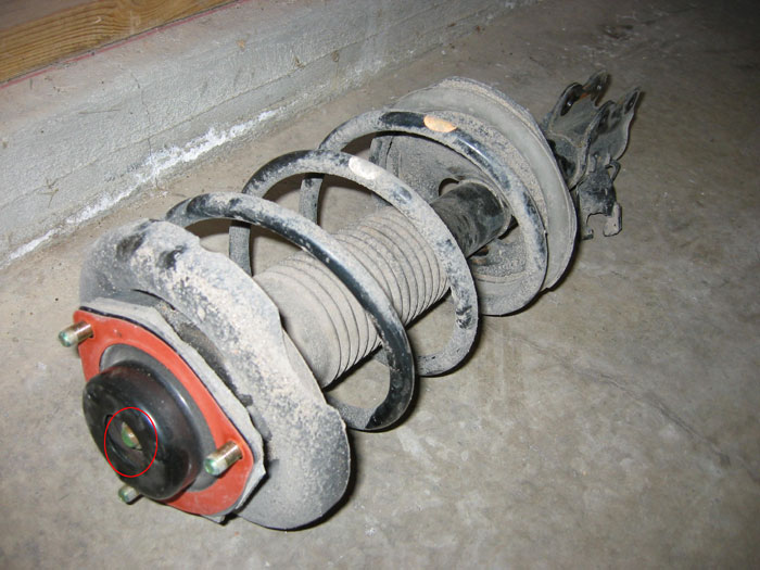
7. When spring is compressed, carefully remove top hat bolt. The top hat bolt is circled in red in image at right, but the spring compressor isn’t installed in this shot.
NOTE: The spring must be compressed sufficiently with a spring compressor before you remove the top hat bolt. There may still be some pressure on the spring, causing the top hat to pop off. Be sure to point the top hat away from you!
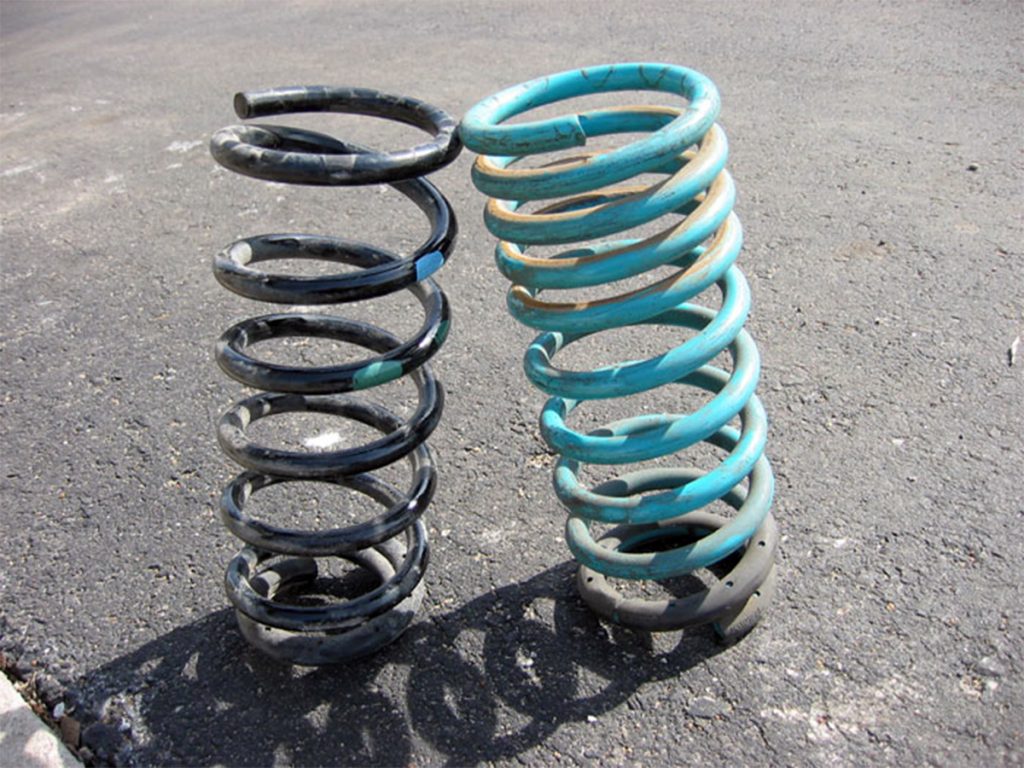
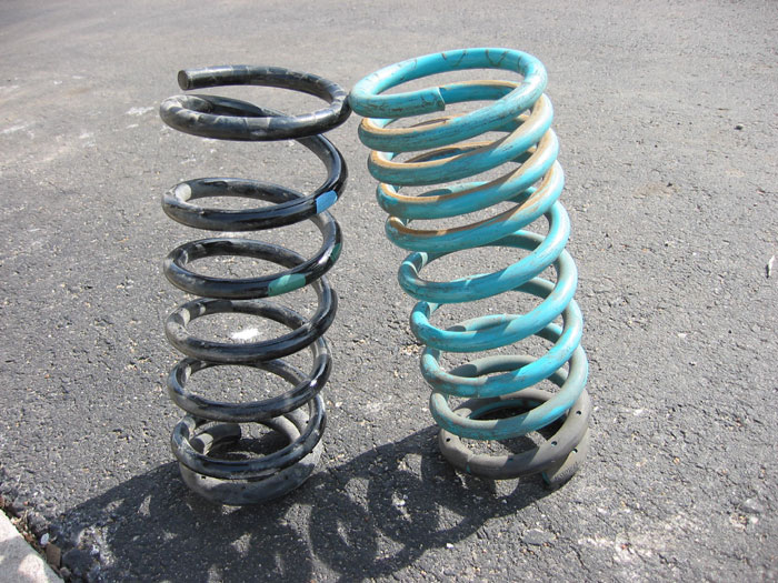
Comparison of OEM front spring and Progress front Spring (on right):
8. OPTIONAL: Trim bump stop with razor blade or box cutters. The bump stop is connected to the dust boot and is circled in orange at the right. Tokico recommends trimming no more than 1/3 – 1/2 the length of the bump stop.
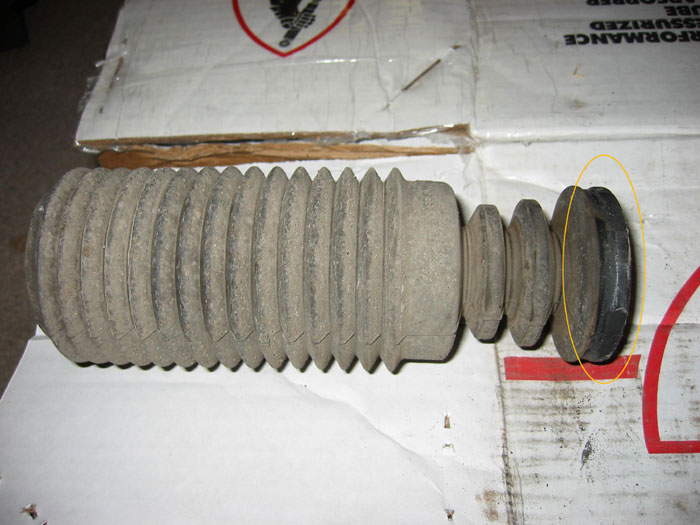
UPDATE: It appears the two rings below the orange circle are considered to be part of the bump stop as well. If anyone can confirm this, please let me know. Nonetheless, I trimmed the part circled in orange off. When I first installed my struts and springs I didn’t trim the bump stops at all and I had problems with the front bottoming out on larger bumps. Since I trimmed, this very rarely occurs. Also, most people running more mild drops (Eibachs, H&R, etc.) don’t trim their bump stops and have no issues. Most spring manufacturers provide detailed instructions on how to trim the bump stops if necessary.
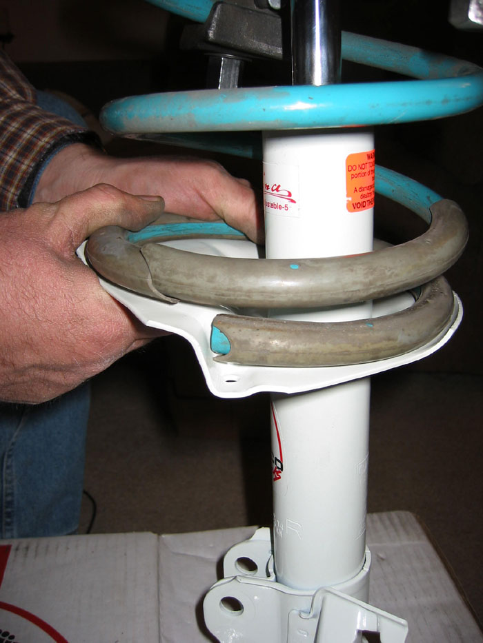
9. Compress new spring with spring compressor and install on strut. Make sure the spring isolator (sleeve – gray in the picture) is installed on the spring and resting on the perch. Though not shown in this shot, the isolator should be positioned to hang off the end of the spring about 1/4″. This will avoid rubbing noises of the spring contacting the perch. Apply 3M rubber seal to attach the isolator to the spring and assure the isolator doesn’t slide around on the spring post install. Also, make sure the end of the spring is resting on the lowest part of the perch as shown at right.
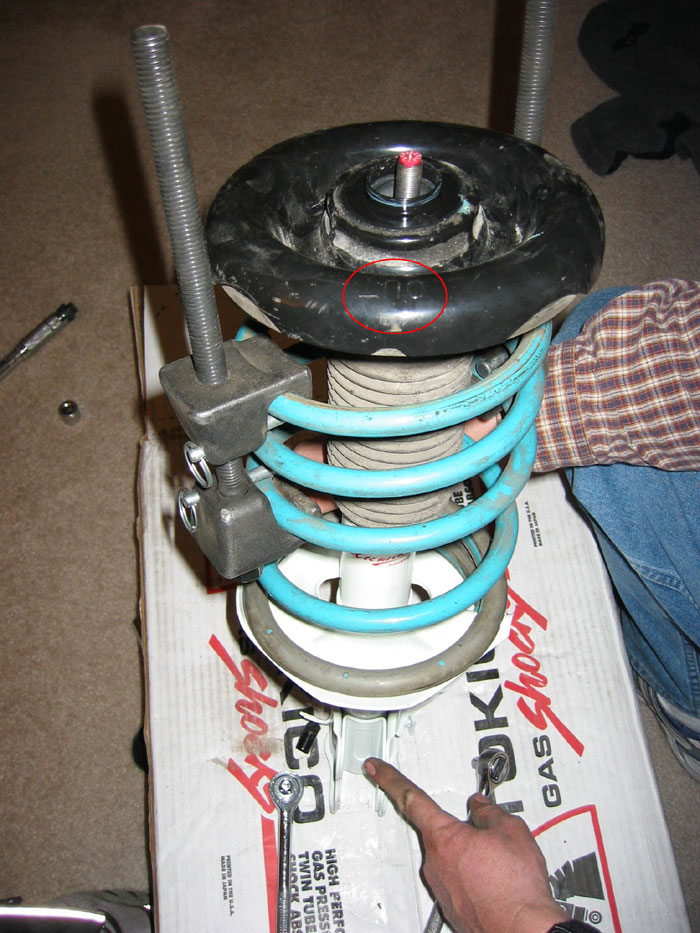
10. Reinstall the top hat. Make sure the “OUT” label on top hat faces out toward the wheel well. It should be on the same side of the strut as the mounting bolts (which are being pointed to in the picture)..
11. Reinstall strut by following the removal steps in reverse order. Use the following torque specs in newton meters (N-m):
– strut to steering knuckle bolts 140-159 N-m
– strut upper mount nuts 39-54 N-m
– piston rod nut (nut that holds down top hat) 59-88 N-m <-NOTE: This is for a factory strut. Follow the torque specs for whatever aftermarket strut you’re installing otherwise.
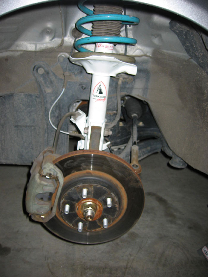
Job half done:
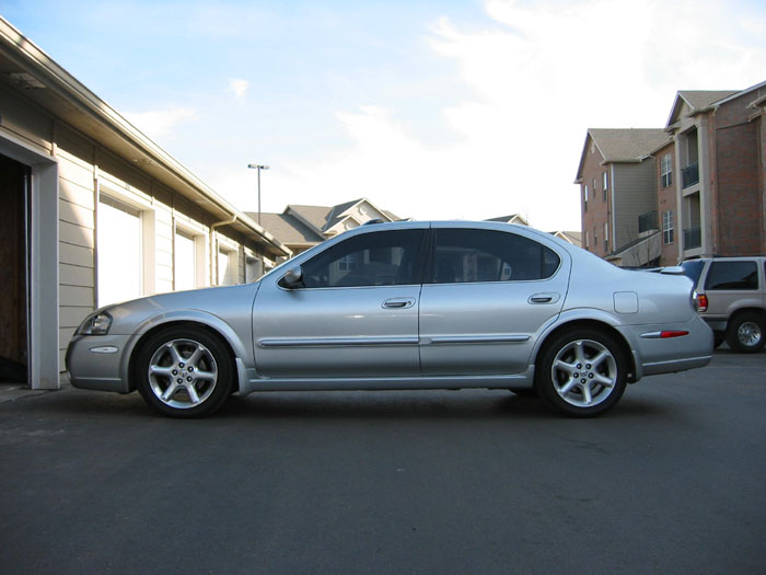
REAR WHEELS
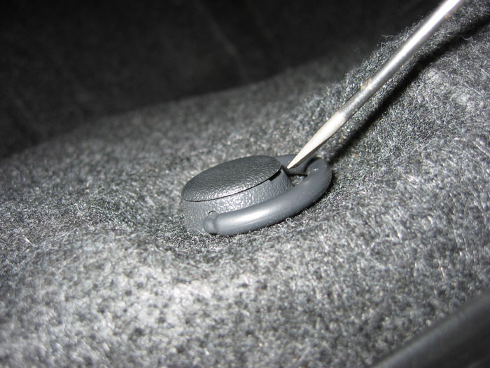
1. NOTE: The first step was formerly to remove the trunk liner, but this isn’t actually necessary. You merely need to pull away the liner over the rear struts by removing the attachments near the seat pass through.
Use a flathead screwdriver to remove the pop tabs by sliding the flathead into the slit on the side and twisting.
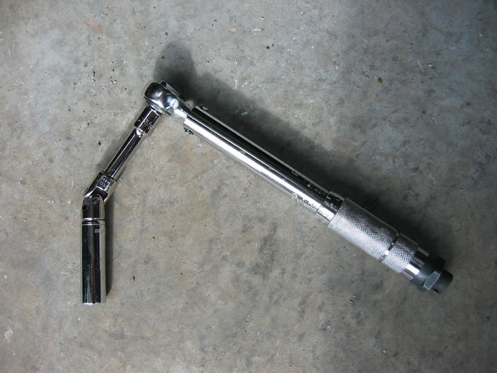
2. Prepare socket wrench with extension, universal joint, and 14mm deep well socket. A longer extension can be substituted for a deep well socket here if preferred. This combo makes attacking the rear strut bolts really easy.
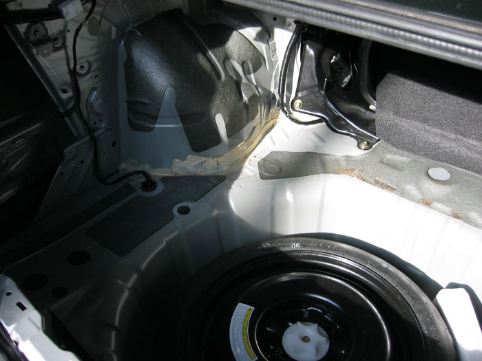
3. Trunk stripped (Totally optional). I removed mine just so you can clearly see the rear strut towers, which are all you really need access to.
4.
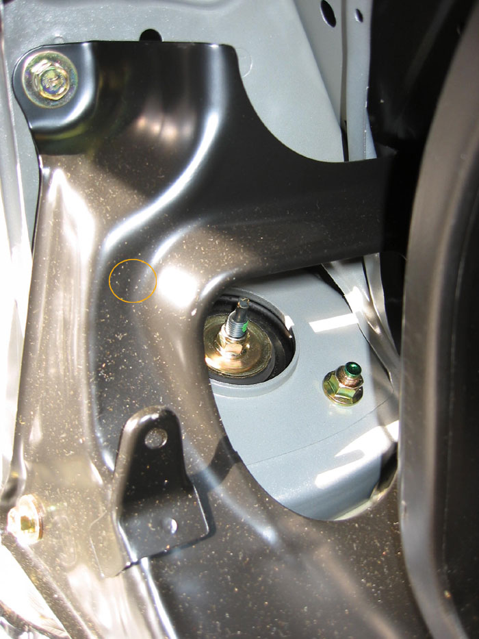
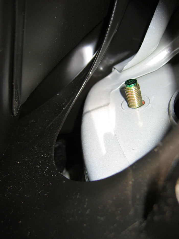
Remove the two outer bolts with the socket setup mentioned above. The nut in the rear is hidden by the metal shield and represented by the orange circle. Attack the nut from above through the higher hole in the shield. The lower strut mount will continue to support the strut after these are removed.
IMPORTANT NOTE: When removing these nuts, make sure not to drop them as they’ll be very difficult to retrieve behind the black metal shield. I’d recommend using your fingers for those last few turns to assure you don’t drop the nuts. A telescopic magnetic tool would also come in handy if you happen to have one.
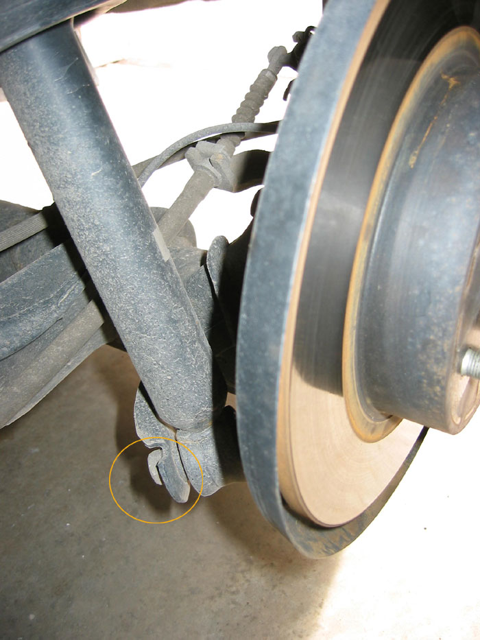
5. Remove the lower strut mount bolt with 17mm socket and breaker bar. Soaking with PB Blaster or WD-40 in advance may help loosen it up. The bolt is circled in orange. The strut will fall when this bolt is removed so be sure to catch it.
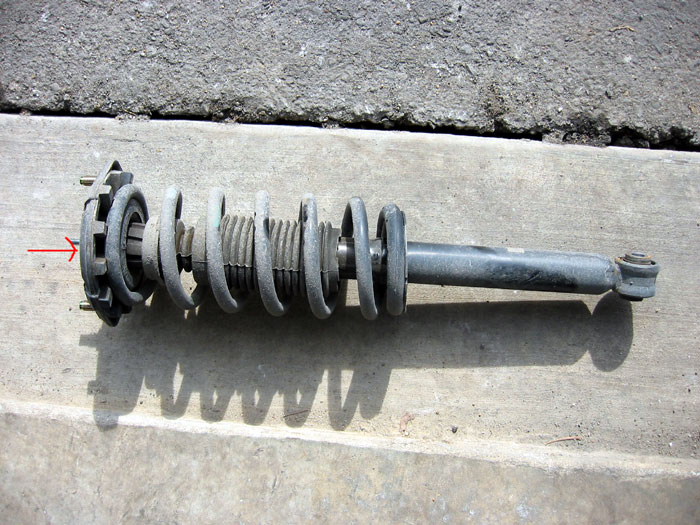
6. Loosen top hat nut with a 14mm deep well socket a little but DO NOT REMOVE YET. This must be loosened before the spring is compressed or the strut shaft will just spin when you attempt to loosen the top hat nut. The top hat nut isn’t visible in the shot at the right, but the red arrow is pointing to it.
7. Compress factory spring with spring compressor. WARNING: Compressed springs can kill. Always point the top of the strut away from you and other people and make sure spring compressor is securely fastened. Once the spring is compressed enough to relieve the pressure on the top hat, carefully remove the top hat bolt.
8.
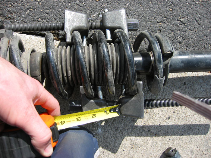
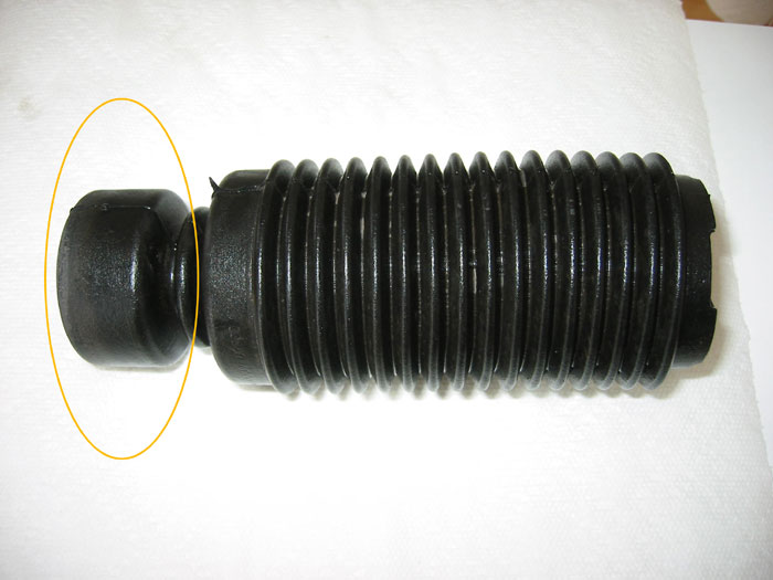
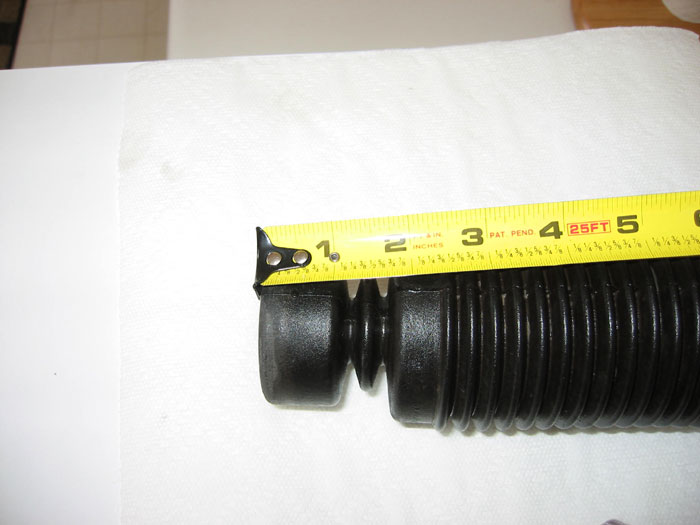
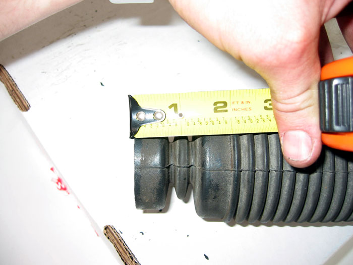
Disassemble strut carefully and take note of parts and order. OPTIONAL: Trim bump stop with razor blade or box cutters. The rear bump stop is connected to the dust boot. Tokico recommends trimming no more than 1/3 – 1/2 the length of the bump stop. I trimmed a little less than 1/2 of the rear bump stops. Some spring manufacturers specify the amount the bump stop should be trimmed.
Bump stop and dust boot unit:
Before trimming:
After trimming:
9. Compress new spring.
10. Install spring on perch. Make sure the spring isolator (sleeve – gray in the picture) is installed on the spring and resting on the perch. Though not shown in this shot, the isolator should be positioned to hang off the end of the spring about 1/4″. This will avoid rubbing noises of the spring contacting the perch. Apply 3M rubber seal to attach the isolator to the spring and assure the isolator doesn’t slide around on the spring post install. Also make sure the end of the spring is resting on the lowest part of the perch as shown in the picture at the right from step #9 for the front strut. The principle is the same. Re-assemble strut and tighten top hat bolt to 59-88 nm <-NOTE: This is for a factory strut. Follow the torque specs for whatever aftermarket strut you’re installing otherwise.
11. Re-install strut assembly on car. You may have to recompress the spring and twist the top hat so the bolts line up properly on reinstallation. Use the following torque specs in newton meters (N-m):
– strut to steering knuckle bolts 140-159 N-m
– strut upper mount nuts 39-54 N-m
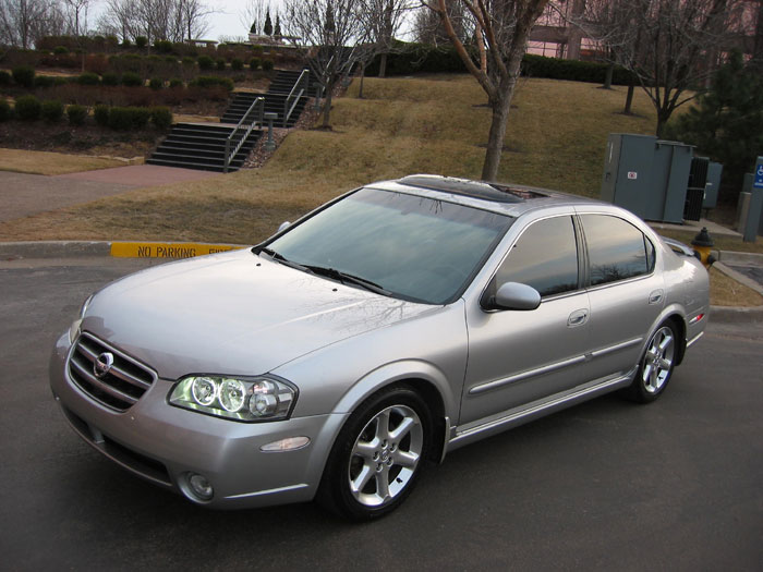
The finished product:
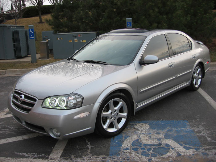
12. If you have any noises, give this checklist a look.
13. Get a four wheel alignment.
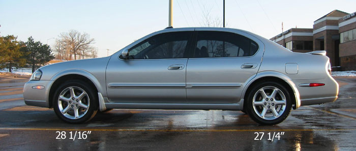
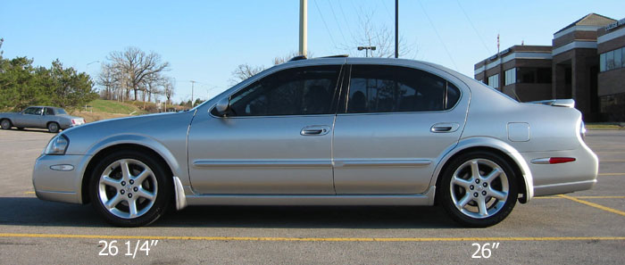
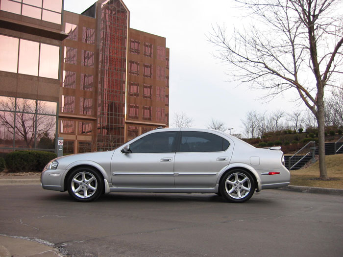
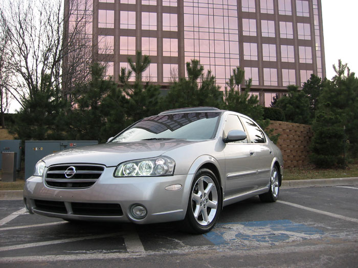
Below are shots of the drop on Progress Springs and Tokico Illuminas:
Distance from ground to center of fender.
Before:
After:
Member Credit: shift_ice
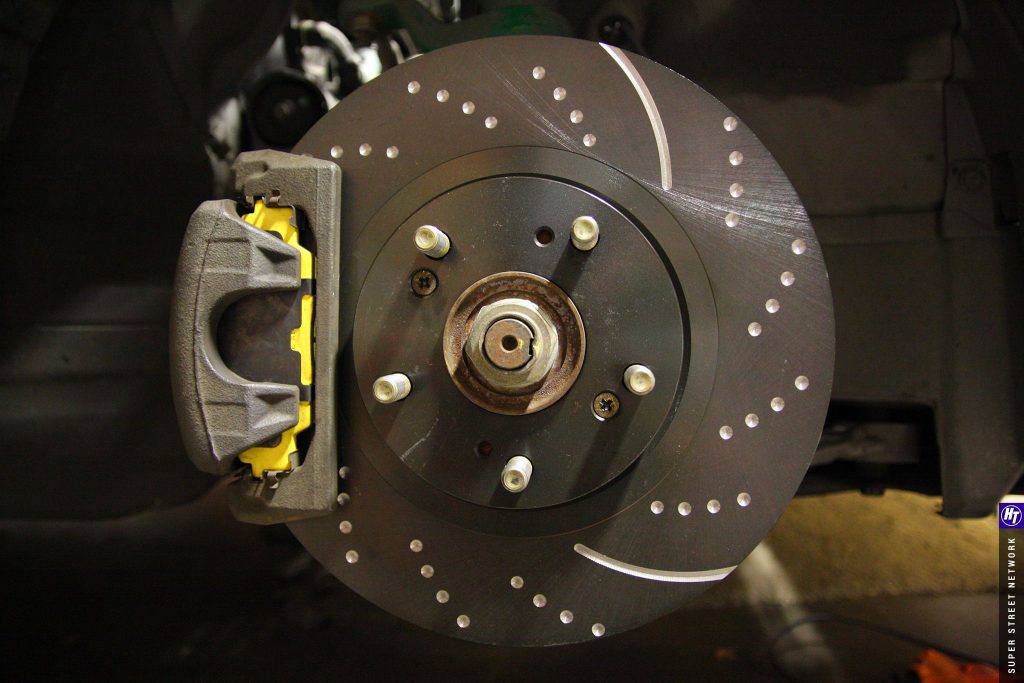
There are many rotor and brake pad options for the Maxima. Check out the brake choice how-to if you’re having problems deciding. In this how-to, I install Hawk HPS pads and Brembo blank rotors, though the process will be the same for any OEM replacements.
The new equipment:
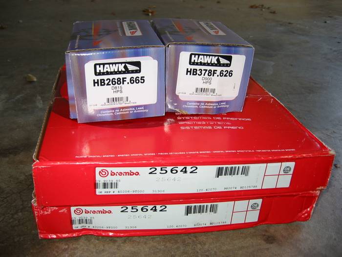
Tools/Supplies:
INSTRUCTIONS:
1. Place car on level ground. This is very important since you’re removing the brakes! Chuck the rear wheels and pull parking brake while doing the front wheels. Jack up the front of the car using the jack point outlined in the manual.
2. Remove wheel using lug wrench
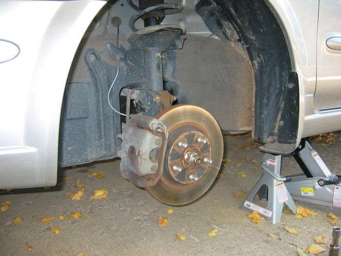
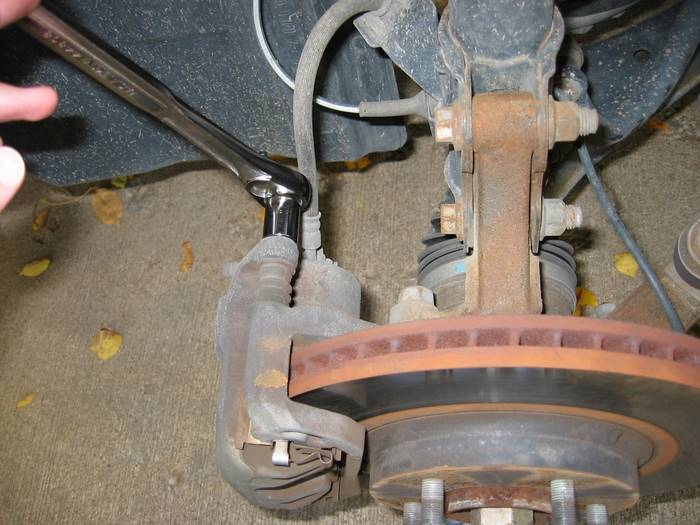
3. Remove the 3 17mm bolts that attach the caliper. There are two on top and one toward the bottom of the caliper bracket.
NOTE: Do NOT remove the bolt that connects the brake line to the caliper. This will introduce air into the brake system and you will have to bleed the brakes to get the air out. The brakes will be very spongy until this is resolved.
So keep the brake line connected and hang the caliper to avoid strain on the line as described in the next step.
Removing the top brake caliper bolt:
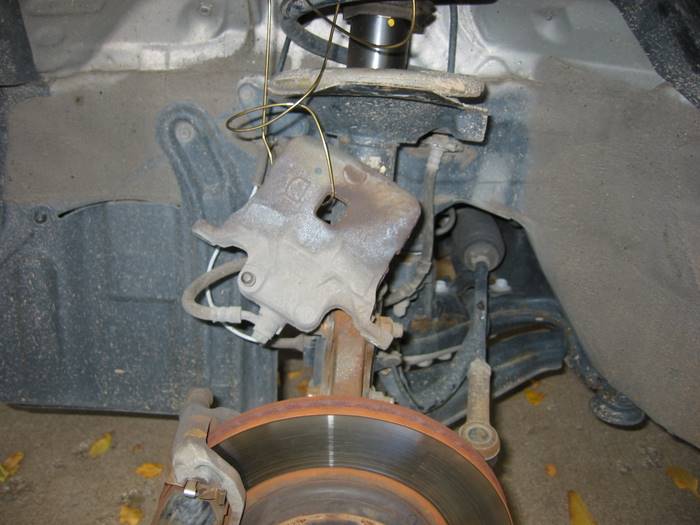
4. The caliper should easily slide right off the rotor after removing the above 3 bolts. Hang the caliper with an old coat hanger from the top of the spring. Never let the caliper hang from the brake line – it can damage the brake line and cause a leak.
Caliper hanging from hanger:
5. Remove the two 19mm bolts on the back of the caliper mounting bracket.
Two bolts circled in red:
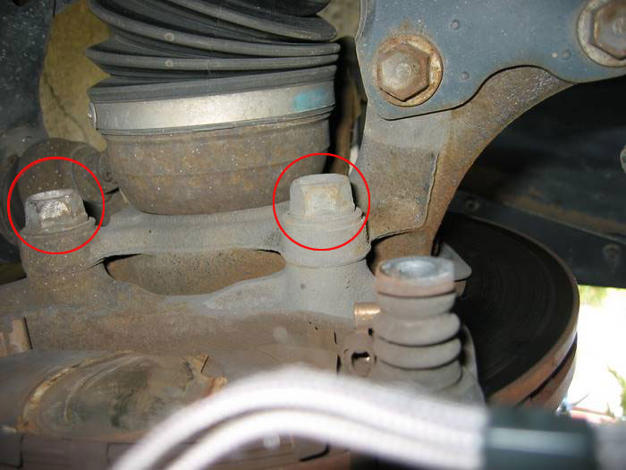
6. NOTE: This step and any steps below relating to the rotor, only apply if you’re replacing the rotors as well. If the brake pedal pulsates when you press on the brake, you might consider replacing the rotors as well. This is typically noticable when braking harder at faster speeds such as when exiting the highway on an offramp.
Remove the rotor. Depending on the age of the vehicle and climate, the rotor may be rusted on. My Maxima was only 3 years old and my rotor was rusted on tight. To remove a rusted rotor there are a number of options:
Apply a liberal amount of WD-40 to back of the rotor and inside the lug holes on the front. Allow to soak. After a few minutes of soaking, use a large hammer and strike the back of the rotor in various locations to help dislodge it. If you are removing the rotor so it can be machined at a shop, be sure to use a piece of old scrap wood so you don’t damage the back of the rotor by striking it directly with a hammer. I started with a rubber mallet but eventually had to use a large steel hammer to knock my rotor loose.
Alternatively, you can use the holes on the caliper mounting bracket to help push the rotor off. This requires a 4″ long, 1/2″ wide bolt with a matching washer and nut.
7. Open brake fluid reservoir and wrap an old rag around it to catch any spill.
8. Compress the caliper pistion using a C-clamp or Caliper piston compressor tool. The C-clamp method only works on the front brakes since the rear piston must be twisted as it is compressed (the piston caliper tool naturally does this). While there are a variety of piston compressor tools, the general premise is to place the flat metal plate inside the caliper and twist the bolt until the strike plate (which rests against the piston) presses the piston back into the caliper. See the picture below. If you choose to use a C-clamp, place the old pad against the caliper piston so the c-clamp doesn’t press directly against the piston and mar the metal.
NOTE: As you compress the piston, the brake fluid level will rise. Keep an eye on the brake fluid level and siphon out any extra fluid or cleanup any spill that occurs. I recommend siphoning out some of the fluid since brake fluid is hard on paint.
Brake caliper compression tool kit:
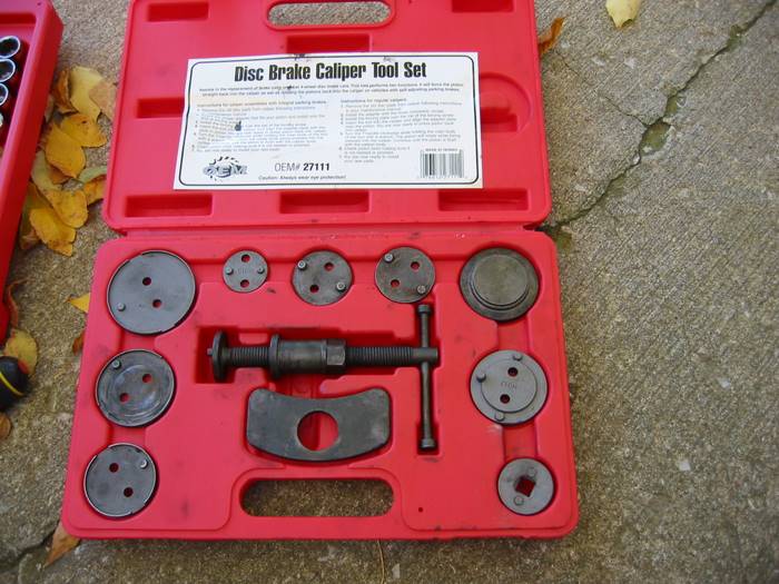
9. Note the orientation of the pads. It’s also good idea to do one wheel at a time so you can always reference the other wheel if you have any question on how to orient the pads on reinstall.
Only one of the two bolts that need removed are visible here:
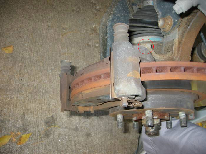
10. Remove the two 19mm caliper mounting bracket bolts (the cradle that holds the pads).
11. If the old rotor was stuck, use a wire brush to clean the hub face. Optionally, you can apply a small amount of grease to the hub face to keep the new rotor from sticking sometime down the road.
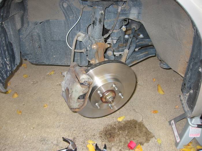
12. Before installing the new rotor, it’s important to clean it off with rubbing alcohol and brake cleaner or rubbing alcohol. Rotors are shipped from the factory with a protective coating to keep them from rusting before sale. Use a liberal amount of brake cleaner and give it a good scrub until it no longer feels like it has a film on it. Once clean, install the new rotor by sliding it over the lugs.
New rotor installed:
13. Remove the old brake pads from the caliper mounting bracket and clean the shims and hardware thoroughly with brake cleanup. Use a clean rag to scrub off deposits. Make sure this hardware is smooth and clean. The pads slide back and forth in this hardware so it’s important to make sure the path is smooth as possible. Once clean, dry them off.
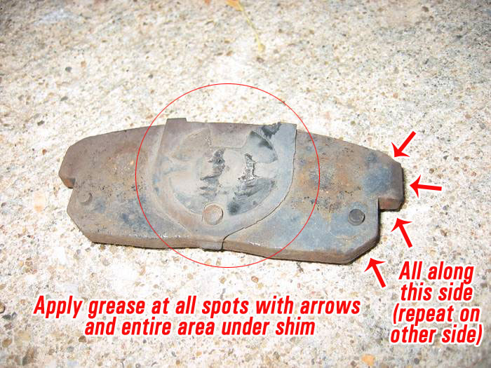
14. Apply grease to all the touch points in the channel where the pads sit. Apply a liberal amount of grease on the back of the brake pads and reinstall the shims. Apply grease to the points on the caliper mounting hardware where the pad will sit.
Apply grease to the following points on the brake pad. This is the back pad so the shim is smaller. Apply a liberal amount of grease to the back of the pad wherever the shim and the pad meet.
Apply grease to the following areas on the brake pad
15. Reinstall caliper mounting bracket and torque bolts to 53-72 ft. lbs. Insert pads back into caliper mounting bracket and slide caliper over the pads.
16. Reattach caliper to caliper mounting bracket and tighten caliper mounting bolts to 16-23 ft lbs.
Completed job:
17. Check brake fluid level. Add fluid from a brand new bottle of brake fluid as needed. It’s important not to use brake fluid that has already been opened because brake fluid soaks up moisture overtime reducing its effectiveness.
18. Reinstall wheel, remove wheel chucks, and lower car.
19. IMPORTANT: You must bed the brake pads after installation. This is very important to help avoid squeaking down the road. The specific bedding procedure is typically provided with the brake pads, but the general rule is to drive around 45 and brake hard, releasing the brake right before coming to a stop. Repeat this process 4 or 5 times.
20. While not required, it’s a good idea to bleed the brakes after doing a brake job.
21. The pictures above are for the front brakes, but doing the back is just the same with a couple minor differences:
Remove the 14mm bolt holding the mount for the emergency brake cable to get the upper part of the caliper off.
The lower piece of caliper has 17mm bolts.
The piston must be turned clockwise to be compressed. Make sure the end of the caliper compressor is inserted properly into the grooves in the piston so the tool actually twists the piston as it compresses.
Hook the emergency brake cable back onto the spring mechanism before reinstalling the upper caliper piece. It’s hard to hook up after the caliper is assembled.
To get the rear caliper back over the rotor, you must turn the cylinder so the nub lines up with the groove it slides into.
Edit: Here’s a few more notes submitted from reader ajahearn:
Some vented rotors are directional so people need to pay attention to the one to install.
Slotted/drilled/dimpled/etc rotors are supposed to be non-directional but some manufacturers want you to install them such that the first dimple/part of the slot/etc that reaches the pad needs to be at the top with the idea that any grabbing will pull the pads inward toward the hub and not force them upward away from the hub.
The caliper should never be left hanging from the brake line – it should always be supported by a hanger or bungy cord.
For the rear piston, the boot may start to bind and make it harder to compress/rotate. To resolve, occasionally back off (counter clockwise) to get the boot to straighten and then start again. And opening the bleed valve makes it considerably easier to turn the piston back in. Of course you need to have a hose to prevent the fluid from spraying
Member Credit: Jevon Gunning
Tools Needed: 14MM
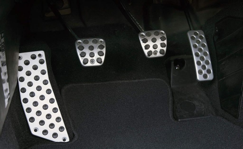
This how-to is very straight-forward and will allow you to get rid of that annoying free play on your manual 6spd or 5spd Nissan Maxima.