If you own a 2005–2006 Nissan Altima SE-R and your oil pressure gauge is reading incorrectly, there’s a good chance the problem isn’t mechanical at all. Nissan built a self-diagnosis mode directly into the combination meter, and it allows you to electrically test all gauges without removing a single part.
This feature is buried in the factory service manual, which explains why so many owners never hear about it.
What This Test Does
The self-diagnosis mode verifies:
Oil pressure gauge
Voltmeter
Fuel gauge
Temperature gauge
Warning lights and cluster segments
If the gauges sweep correctly, your issue is likely a sensor or wiring input, not the cluster itself.
Official Nissan Gauge Self-Diagnosis Procedure
This procedure comes straight from the Meter/Gauges Operation – Self-Diagnosis Function section of the service manual.
Turn the ignition ON
Use the odometer/trip button to select Trip A or Trip B
Turn the ignition OFF
Press and hold the odometer/trip button
While holding the button, turn the ignition ON
Confirm the trip display shows “000.0”
Within 7 seconds, press the odometer/trip button at least 7 times
If done correctly:
All cluster segments illuminate
The low-fuel warning lamp turns on
The cluster enters diagnosis mode
Each press of the trip button will then cycle and indicate each meter/gauge individually, as shown in the factory illustration.
Why This Matters for Oil Pressure Issues
Many Altima SE-R owners assume a bad oil pump or engine issue when the oil pressure gauge acts up. This test lets you rule out the gauge and cluster instantly.
❌ Gauge does not respond → cluster or internal electronics issue
I spent far too long hunting down wiring diagrams before finding this page in the manual. Hopefully this saves someone else hours of unnecessary troubleshooting.
PROCEDURE WAS DONE ON MY 2008 M45. PROCEDURE SHOULD BE SIMILAR ON MOST INFINITI VEHICLES. MAKE SURE TO CHECK YOUR OWNERS MANUAL FOR PROPER FLUID SPECS AND CAPACITIES.
TOOLS:
JACK STANDS
JACK
10MM HEX SOCKET
SOCKET WRENCH
TORQUE WRENCH (FT/LBS)
BREAKER BAR (IF NEEDED)
SUPPLIES:
2 (QUART) BOTTLES DIFFERENTIAL GEAR OIL (75W-90 SYNTHETIC IS WHAT I USED)
FLUID PUMP
DRAIN PAN
RAGS
SAFETY:
NEVER GET UNDER A CAR WITHOUT OUT QUALITY JACKSTANDS OR RAMPS IN PLACE. NEVER EVER GET UNDER A CAR ONLY RAISED AND SUPPORTED WITH A JACK.
PROCEDURE:
LIFT AND SUPPORT ALL 4 CORNERS OF YOUR VEHICLE WITH JACKSTANDS. YOU WANT TO KEEP THE THE CAR AS LEVEL AS POSSIBLE SO YOU WILL BE ABLE TO PUMP IN THE CORRECT AMOUNT OF FLUID INTO THE DIFFERENTIAL.
LOOSEN AND REMOVE THE TOP FILLER PLUG FIRST (YOU’LL WANT TO REMOVE THE FILLER PLUG FIRST SO YOU CAN BE SURE THAT YOU WILL BE ABLE TO FILL UP THE DIFFERENTIAL AFTER THE FLUID IS DRAINED).
LOOSEN THE DRAIN PLUG. ALIGN YOUR PAN UNDER THE DIFFERENTIAL AND REMOVE THE PLUG.
LET THE FLUID DRAIN COMPLETELY.
AFTER THE FLUID DRAINS, CLEAN THE DRAIN PLUG AND REINSTALL THE DRAIN PLUG. TIGHTEN THE DRAIN PLUG TO 25FT/LBS.
GRAB YOUR FLUID AND PUMP AND FILL YOUR DIFFERENTIAL UNTIL THE FLUID STARTS COMING OUT OF THE FILLER HOLE. YOU MIGHT HAVE SOME FLUID COMING OUT SLOWLY THE WHOLE TIME YOU ARE PUMPING, BUT IT WILL NOT BE FULL UNTIL IT IS COMING OUT PRETTY GOOD (AROUND 1.7 QUARTS).
AFTER THE FLUID IS LEVEL WITH AND COMING OUT OF THE FILLER HOLE PUT BACK THE FILLER PLUG AND TIGHTEN TO 25FT/LBS.
CLEAN UP ANY FLUID THAT YOU SPILLED, ESPECIALLY OFF THE EXHAUST PIPES.
DONE!
MY CAR HAD AROUND 39,000 ON IT, NOT SURE IF THE FLUID WAS EVER CHANGED BEFORE I DID IT.
OLD FLUID ON LEFT / NEW FLUID ON RIGHT.
The rear O2 sensor (downstream of the cat) failed. I had both codes 0512 and then 0912. This lights up the SES warning lamp, but the ECM does not use any other signal from the rear O2 sensor as input to manage the fuel and ignition system in a closed-loop operation. The only purpose of the rear O2 sensor is to monitor the function of the catalyst. So I didn’t care much about having a functioning rear O2 sensor. I wanted a creative solution to turn off the SES lamp. A search on eBay resulted in an “O2 sensor simulator”.
I ordered one unit and installed it. My installation also included 2 additional 25 ohms resistors rated for 15 Watt load to simulate the O2 heater function. The ECM also monitors the heater function of the O2 sensor. So I had to take care of that error code as well to have the ECM turn off the SES lamp. I tapped in the 2 resistors in series in place of the heater wires. As an alternate to resistors, I think a simple 12V 3Watt automotive bulb ( No 194) could have simulated the heater function of the O2 sensor.
The whole installation went smooth, and the ECM switched off the SES lamp. I recommend very much the DualO2Sim. It costs much less than a genuine rear O2 sensor. Please remember this simulator works only for the rear (post catalyst) O2 sensor.
The simulator is offered at $30. A genuine O2 sensor costs at least $60. I can make a write-up. I will post it later.
Wanted to share my experience with all.
Installation of the O2 sensor Simulator
The rear O2 sensor has 4 wires (on my 1998 Maxima).
Black: low Voltage (0.1 to 0.9 V) very low amperage signal generated by the sensor itself
Grey: car chassis ground
White: the O2 sensor heater 12V positive feed ( switched on with ignition key)
White: the O2 sensor heater ground (not connected with wire 2- ground, not the same. This wire runs to fuse number 31 (1999 model year ) or 34 ( 1995-1998 model year) ).
To install the O2 sensor simulator:
Cut all 4 wires of the O2 sensor. Cut the wires close to the bad O2 sensor. That will give you some good wire length after the connector located under the driver’s seat. (On my 1998 Maxima the connector is located under the driver’s seat. This is where the O2 sensor wires emerge from under the car through a rubber grommet). Leave the bad O2 sensor in the exhaust pipe.
The sensor simulator also has 4 wires:
a – red : a 12V input to feed the simulator
b – black: ground
c – and d: 2 purple wires: O2 simulated signal ( one for each actual O2 sensor if the car is equipped with rear O2 sensors).
Use a voltmeter to identify which of the white wires above (3- or 4- ) is the +12V feed. The voltmeter will show a +12V signal with wire 3-. Connect this wire with wire a-.
Connect wire 1- with wire c- or d-. (My car only had one O2 sensor ). Leave the other purple wire unconnected if you have only one rear O2 sensor.
That will take care of ECM code 0512 Downstream oxygen sensor high voltage fault.
In my case, I also had to simulate a functioning O2 sensor heater. I used 2 x 25 ohms resistors (rated for 20 watts each) and connected in series them between wires 3 and 4. Polarity is not important for these. Under 12 V these should dissipate 1.5 Watt each, with 0.24 amps running through them. Be careful where you locate these because they get hot. Not burning hot, but hot. I tied these down under the driver’s seat. I estimated this area had enough open air to dissipate the heat. That took care of ECM code 0902 (Downstream oxygen sensor heater or circuit fault).
I have not tried but I think a simple 3Watt automotive bulb (No. 194 for example) connected between wires 3 and 4 will do the job of fooling the error code 0902.
I found the O2 sensor simulator on ebay.com Look for “O2 sensor simulator”. The supplier, Baker electronics, includes detailed electrical schematics for installation. This simulator will not detect a malfunctioning catalyst. Therefore check with your local regulations for compliance with such an installation on your car.
From khemraj1999
Thought I’d revive an old thread with some pics to help others with an o2 sim install on my 1997 Maxima. I followed twiggy144’s wire codes and o2simulator.com’s installations codes.
I used a sharp knife to slice through the plastic on the wires (DONT CUT). The o2 sensor wires are hard to work with, so I sliced the harness wire. I also left the o2 sensor in to simulate the heater signal but I cut the Sensor’s signal wire (black).
So following twiggy’s instructions:
Find the signal from the o2 sensor (my case, black)
Find ground (grey)
Find 12v. (white, tested with a test light by toggling ignition)
Connect o2 sim to them, then cut the signal from the o2 sensor.
If u need to get rid of the sim..just pull wires out and tape up the slice. (no cuts involved..except the cut from the o2 sensor signal wire..my sensor was failing so I didn’t care.
Rebuilding transmissions can get tricky, especially when it comes to special tools. Of course, buying tools is a necessary part of our job. That being said, sometimes getting these tools can become difficult and expensive. In these cases making your own tool is the way to go.
In this article, we’ll show you how to check the fluid level on the JF017E CVT transmission. We’ll use a 2014 Nissan Pathfinder as our test car. This particular vehicle has a filler pipe with no dipstick (figure 1).
We’ll cover three methods for checking the fluid. In all three examples you’ll want to start the engine and put the shifter into each position for five seconds each. After that, put the engine back in park and leave the engine running.
The first method uses Nissan’s special tool: KV311039S0.
Before you check the fluid level use your scan tool and make sure the transmission fluid temperature is between 95°-113°F. If the fluid temperature is not within this range you’ll get an inaccurate fluid level.
Next, raise the vehicle up and remove the overfill plug (figure 2). This plug is located on the lower bell-housing. With the plug removed you should see fluid dribbling out the hole. If the fluid level is low, attach this tool to the overfill plug and pump fluid into the transmission until it begins to dribble out.
Next we’ll use Nissan special tools: J-51155 and J-52611. One is a quick-check gauge and the other is a charge pipe cap release tool. Nissan has a TSB (NTB18-055b) that details the use of the tool.
The great thing about this is that you don’t have to raise the vehicle in order to check the fluid level. The bad thing about it is that it’s hard to find. We tried a local dealer and were unable to get them. We did find them on Nissan’s Tech Mate site for about $260 www.nissantechmate.com, but always check with your local supplier first. Whether you buy the tool or make your own (as we’ll cover next) it’s a great site to have in your collection of bookmarks. Nissan details the use of the tools in TSB NTB18-055b but here’s the gist of it.
As before, you’ll want to check the fluid temperature with your scan tool although this time you’ll want the temperature between 170°-180°F.
Remove the pipe cap using tool J-52611. If you want to save $20 you can release the cap with a small screwdriver instead. Now we’ll measure the fluid with tool J-51155.
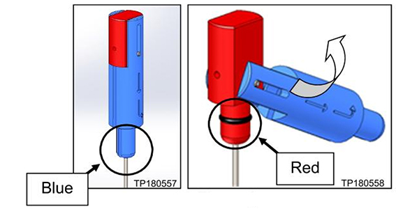
The J-51155 tool is basically two dipsticks in one (figure 3). The handle is both red and blue. The blue part of the handle is a spacer so depending on its position the dip stick will read differently. This gives the tool two distinct depths for the dipstick, based on the model car you’re working on. The chart in figure four shows you which setting to use. The chart also shows you which mark on the dipstick to use for each vehicle.
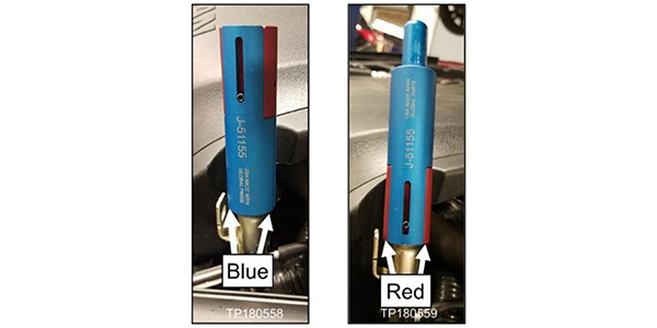
Using the 2014 Nissan Pathfinder as an example and referring to figure 4, you should use the red position handle to measure the fluid height (figure 5). The measured height on the dipstick should be between 14mm-22mm.
If the oil level is low, add fluid and recheck until you have the correct level. The tool makes it easier to recheck fluid levels after driving because you can check the fluid level with the vehicle on the ground.
If you don’t want to purchase the tool, all you need are two spare dipsticks to cut and add measurements to. The filler tube is about 5/8” so when we measure out the dipstick length keep in mind where the tube is going to sit on the dipstick. The measurements are shown in figure six.
Cut two dipsticks to length, one at 25 1/8” and the other 23 1/8” long. From the end of the dipstick lay out the measurements. Mark out 10mm division until you have measured out 60mm. Use an engraver or a punch to label the measurement. The procedure is similar to the J-51155 tool and before you check the fluid make sure the fluid temperature is correct.
That’s it, you just saved yourself a lot of money and have a simple way to measure the fluid level.
Some of our homemade tools save us the most time and money. This one will be one of your installer’s favorite tools in the future.
Steps 1 through 6 will ensure that CVT fluid is properly distributed throughout the transmission.
Models
2013-2018 Altima Sedan
2015-2017 Quest
2016-2019 Maxima
2014-2019 Rogue
2015-2019 Murano
2017-2019 Rogue Sport
2013-2019 Pathfinder
2017-2019 Sentra Turbo
*APPLIED VEHICLES equipped with CVT ONLY
Figure 1
Special tools CVT Oil Level Quick Check Gauge (J-51155) and CVT Charge Pipe Cap Release (J-52611) are now available from Nissan and dealers, Figure 1 and 2. Also, tools can be obtained from Tech-Mate at 1-800-662-2001.
Figure 2
Checking CVT Fluid Level
Steps 1 through 6 will ensure that CVT fluid is properly distributed throughout the transmission. A video on how to use tools is available on nissantechmate.com. Search for J-5261 and then select the Charge Pipe Cap Release Tool.
1. Park the vehicle on level ground (engine running, parking brake set).
2. Using a scan tool, ensure that the CVT fluid operating temperature is within the range of 170°F-180°F (77°C-82°C).
3. Shift the transmission into REVERSE for 5 seconds.
4. Shift the transmission into DRIVE for 5 seconds.
5. Shift the transmission into REVERSE for 5 seconds.
6. Shift the transmission into PARK.
Figure 3
7. Install special tool CVT Charge Pipe Cap Release (J-52611) where shown in Figure 3.
NOTE: The tool shown in Figures 3 and 4 is the same as the one shown in Figure 2, but looks slightly different.
Figure 4
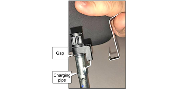
8. Squeeze the tool toward the cap, and then slightly lift the cap (see Figure 3). The cap’s locking tab is unlocked while squeezing. Notice the gap between the cap and charge pipe in Figure 4.
Figure 5
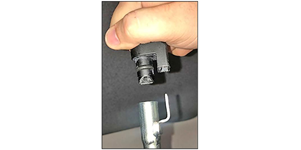
9. Remove tool J-52611 from the cap (see Figure 5).
Figure 6
10. Pull to remove the cap from the charging pipe. Tool CVT Oil Level Quick Check Gauge (J-51155) can now be used to determine the CVT fluid level. The handle on tool J-51155 has two positions, red and blue (see Figure 6and 7). Refer to Table A for the correct position for a given vehicle.
Figure 7
11. With the vehicle in PARK and the engine running, insert tool J-51155 into the pipe. Make sure to use the correct handle position (refer to Table A and Figure 8).
Figure 8
Table A
2013-2018 Altima Sedan (QR25): 23-30mm (blue)
2013-2018 Altima Sedan (V035): 14-22mm (red)
2016-2019 Maxima: 14-22mm (red)
2015-2019 Murano (non-hybrid): 14-22mm (red)
2013-2019 Pathfinder (non-hybrid): 14-22mm (red)
2015-2017 Quest: 14-22mm (red)
2014-2019 Rogue (US. and Japan built) (non-hybrid) : 44-51mm (blue)
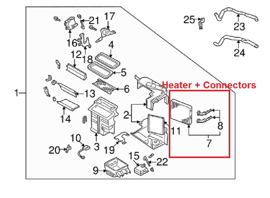
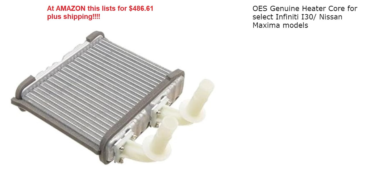
If you own a Maxima, especially an older, high-mileage one (mine is 24 years old with 251,821 miles), be aware: The plastic Heater Core Water Connectors are a ticking time bomb.
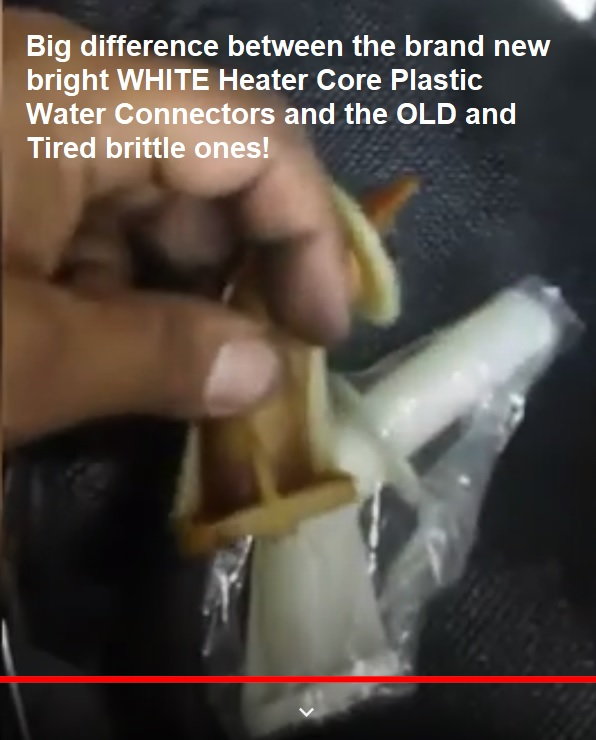
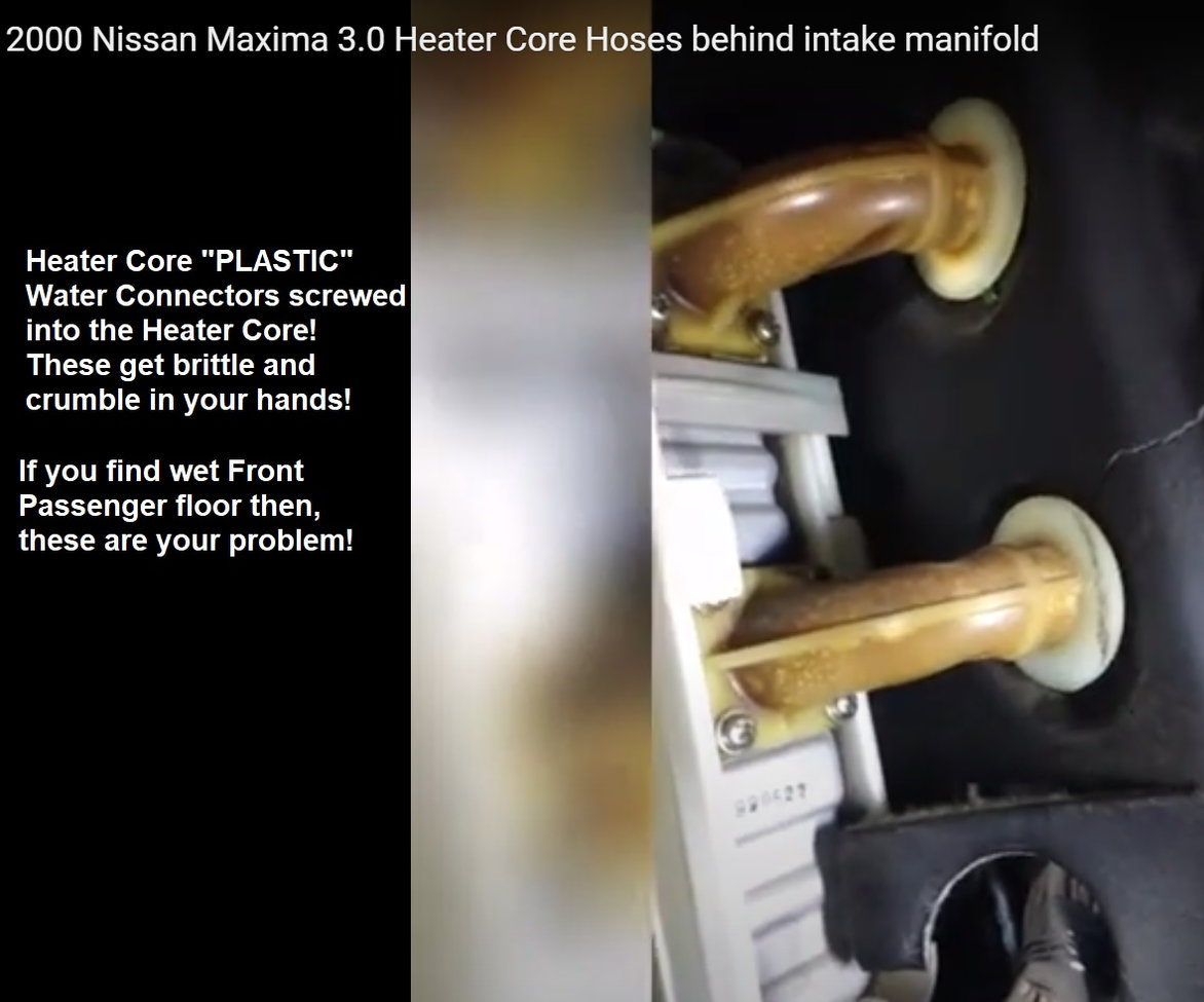
I learned the hard way. In Nov 2022, my radiator and coolant reservoir ran dry, overheating and destroying my original engine. I initially blamed an aftermarket thermostat, but I’m now convinced the real culprit was the plastic Heater Core connectors that screw into the heater core.
Signs to watch for:
Wetness on the front passenger floor → usually a leaking connector.
Dropping coolant levels.
If ignored, you could be looking at catastrophic engine failure.
Costs & Repairs:
Full Heater Core + 2 connectors (OEM): ~$500 (parts only, labor extra, and it’s a nightmare job).
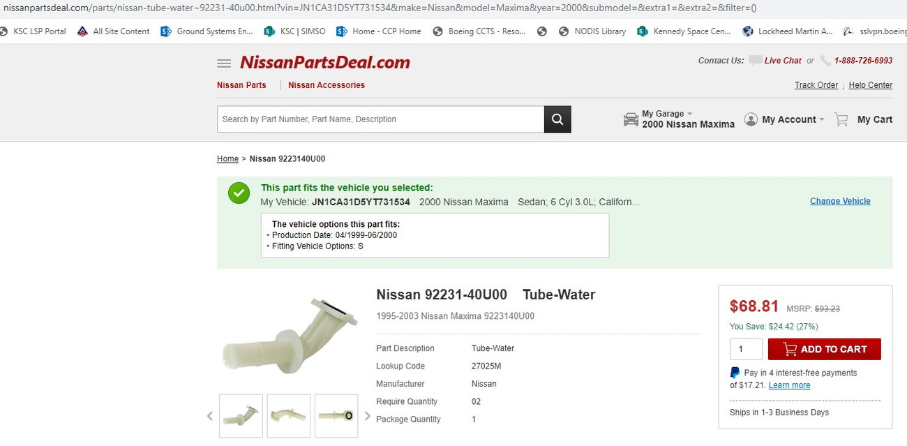
Just the two connectors: ~$80+ each, plus shipping.
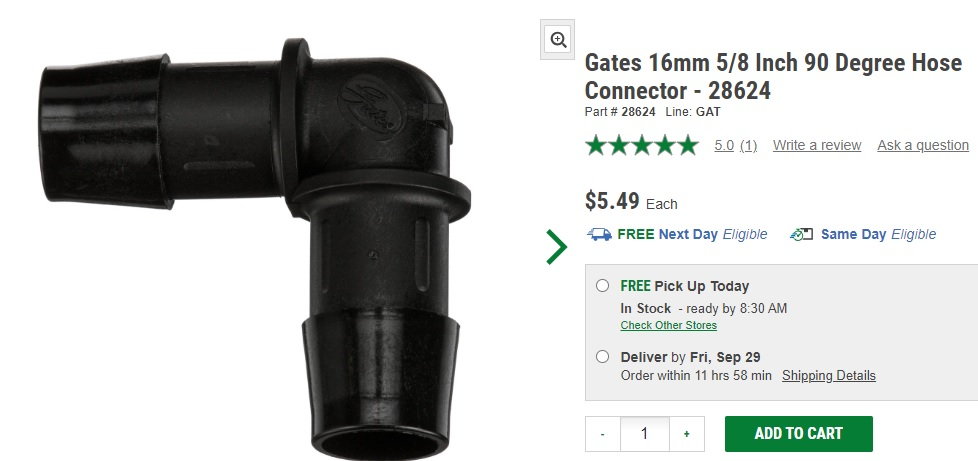
My Solution: Since I live in Central Florida (where heaters are useless), I bypassed the Heater Core completely. I installed a Gates 5/8” water bypass tube between the hoses and left the heater abandoned in place.
No more worries about failed plastic connectors — and honestly, who needs heat in Florida?
This was my solution and it works! Saved me $900+ US by just leaving the Heater Core and those ugly Plastic Water Connectors abandon in place!


")


")


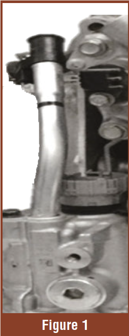
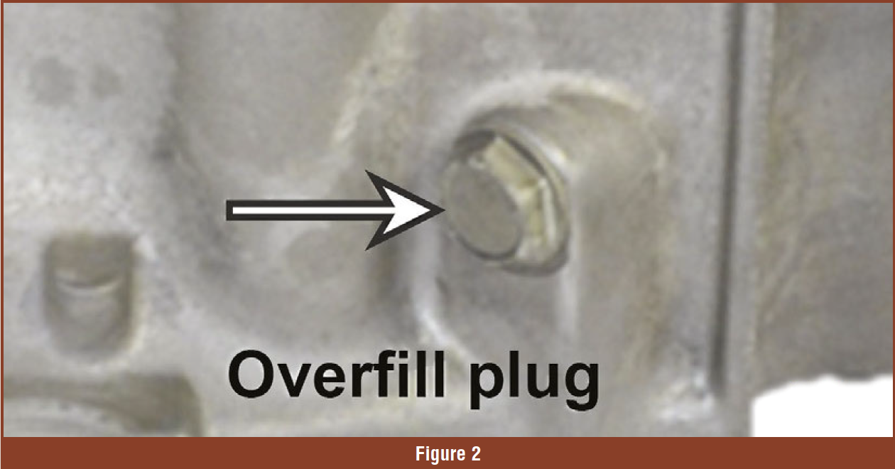
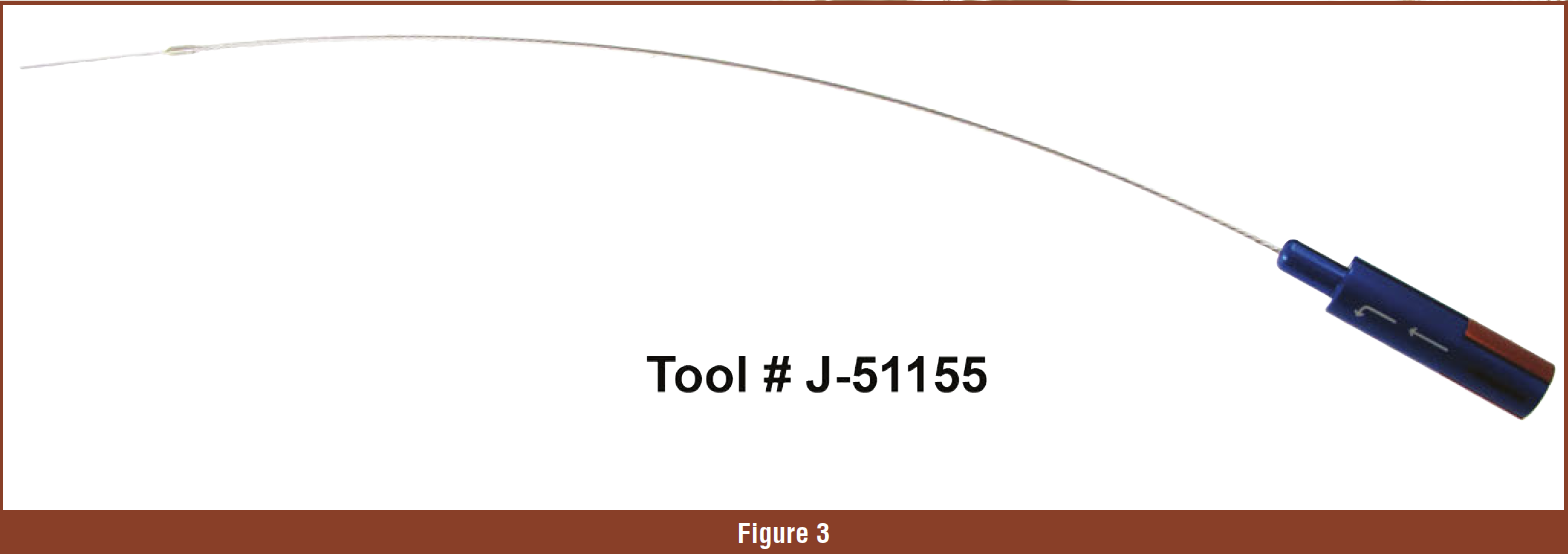
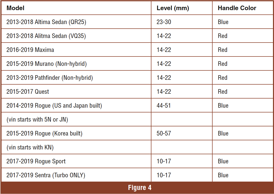
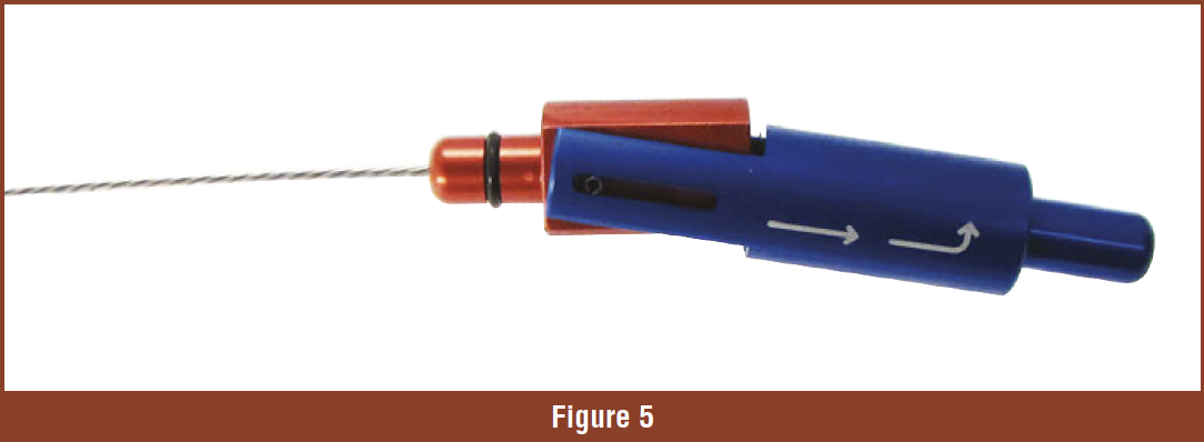
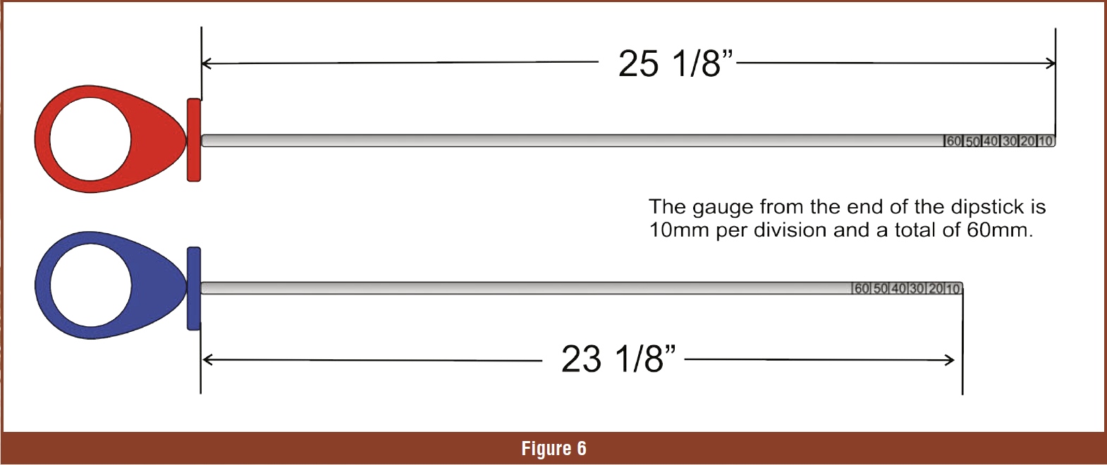


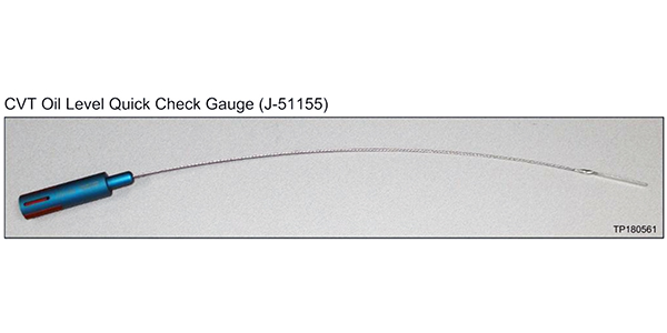
 Figure 2
")