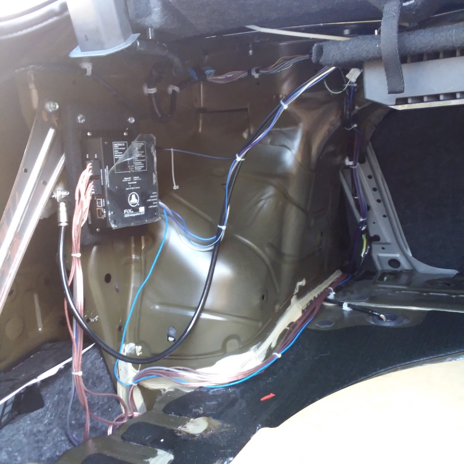
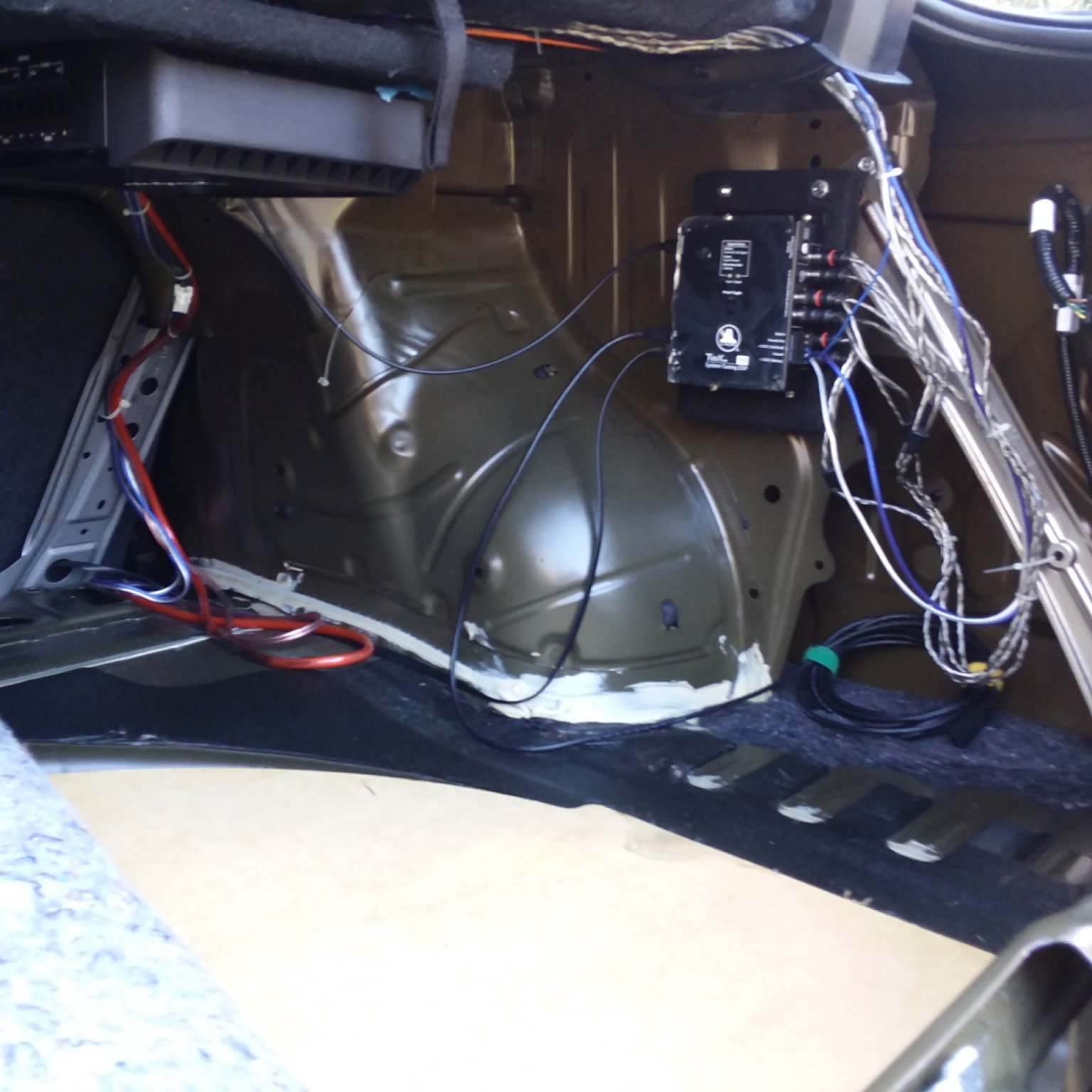
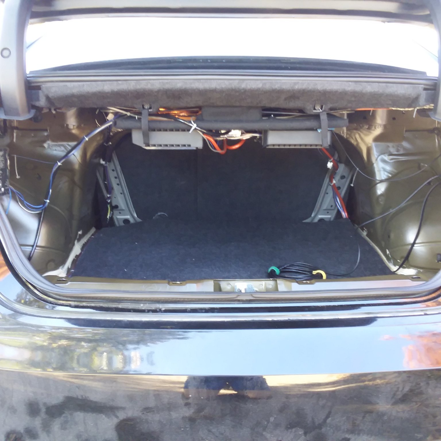
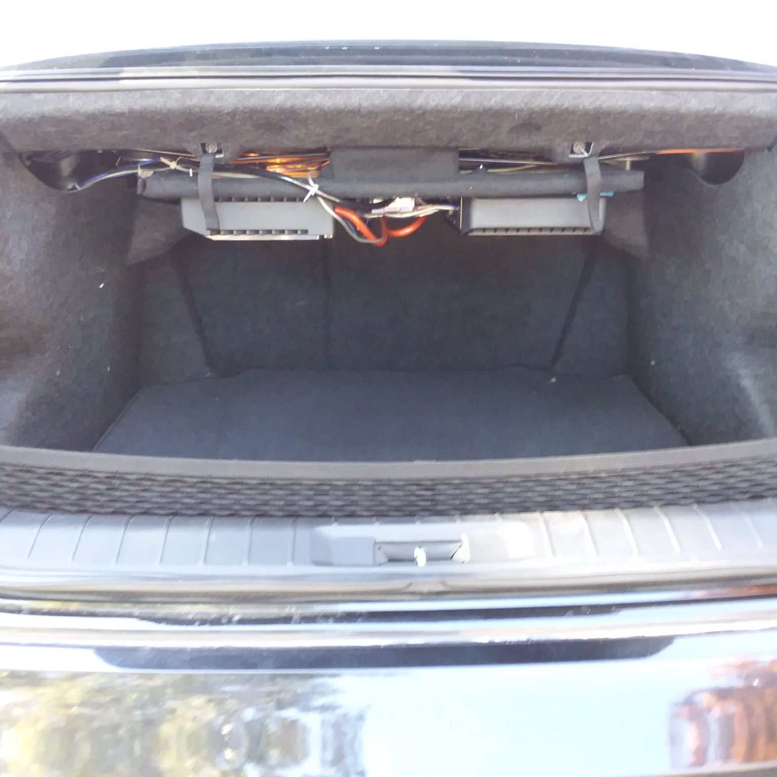
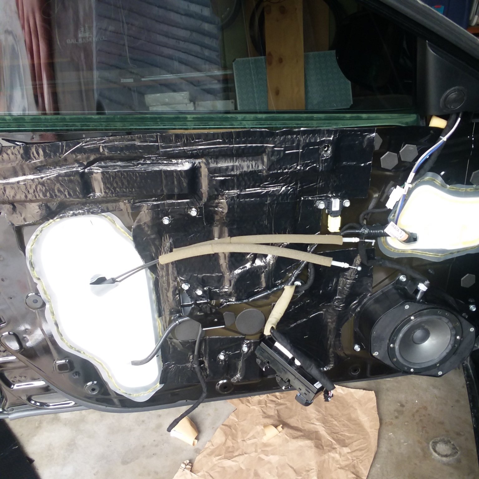
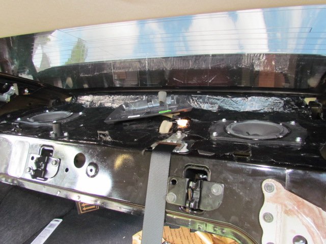
Community Member Credit: James Rice
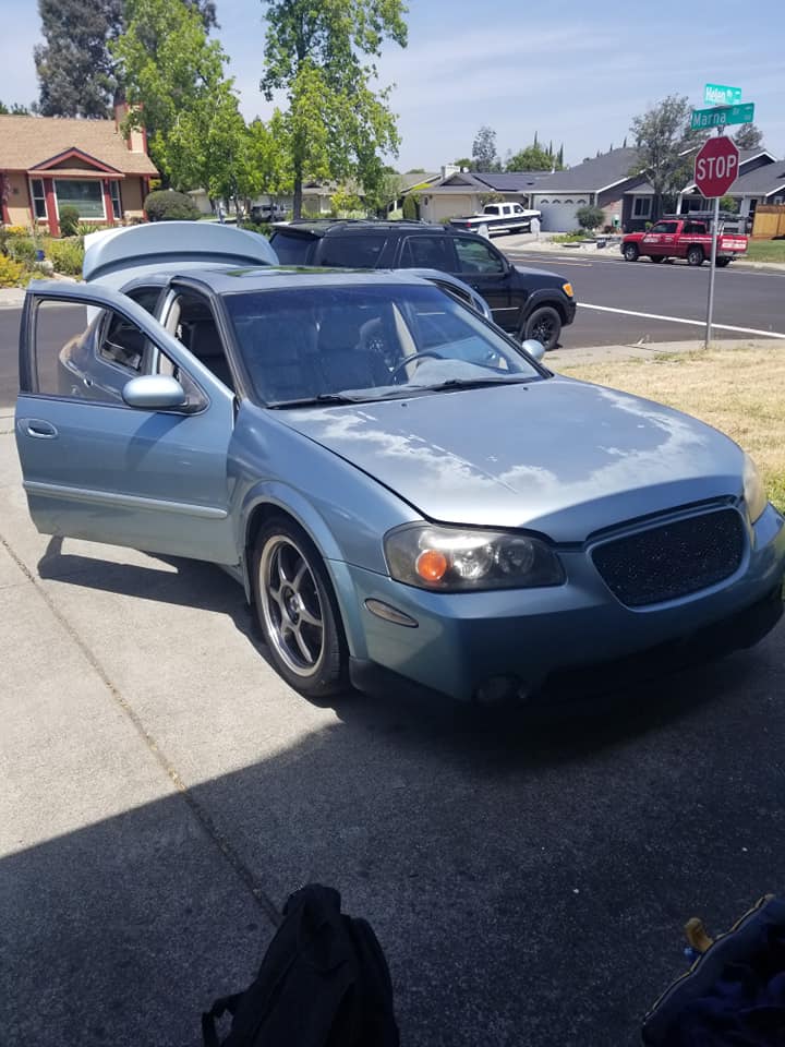
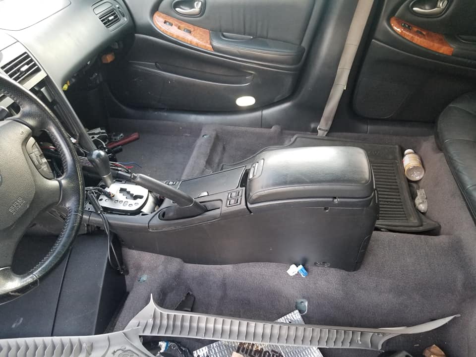
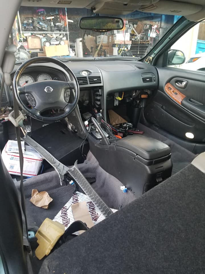
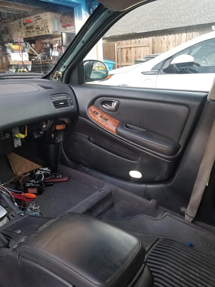
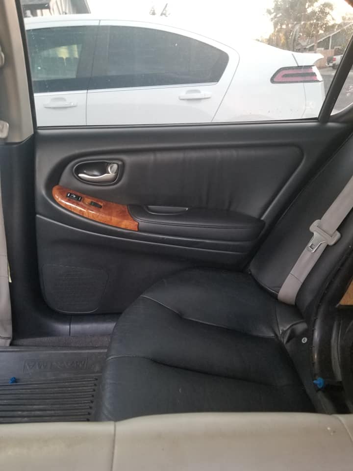
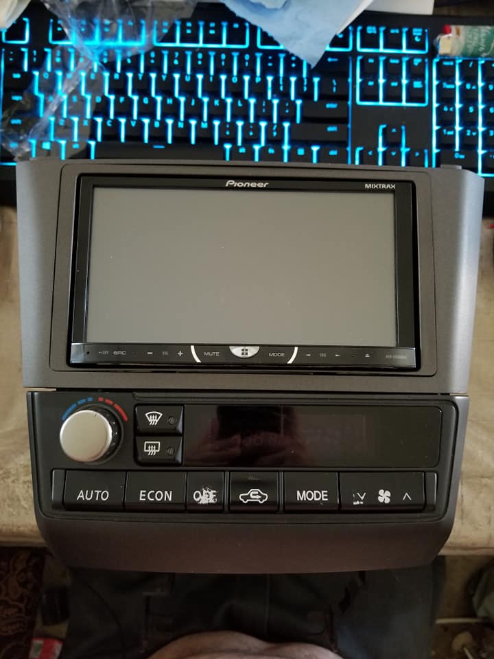
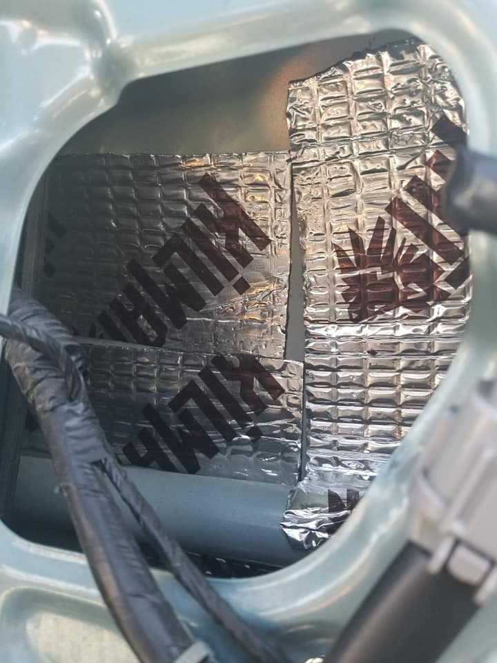
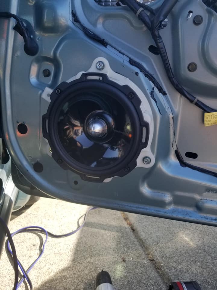
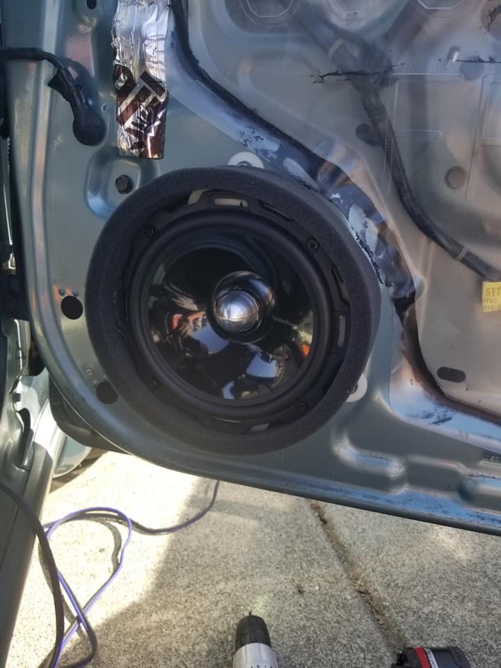
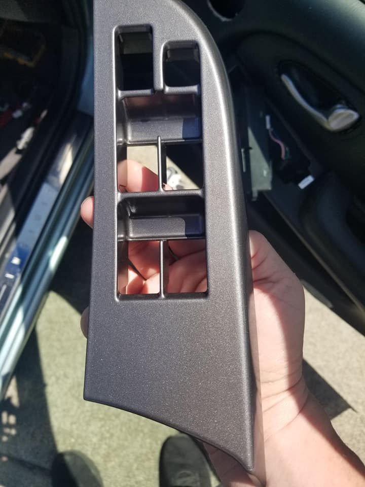
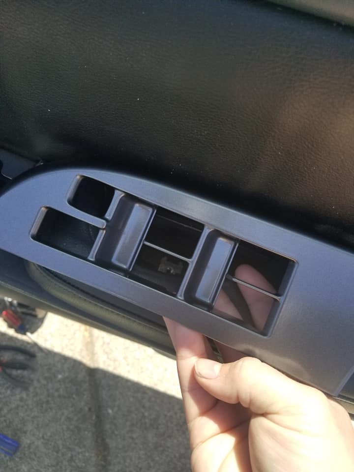
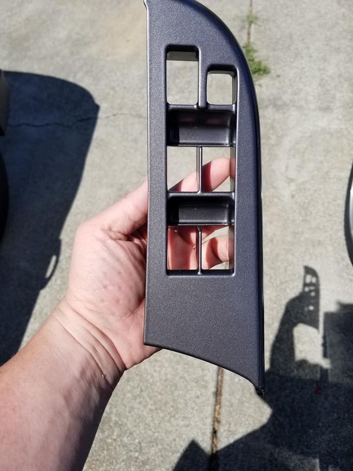
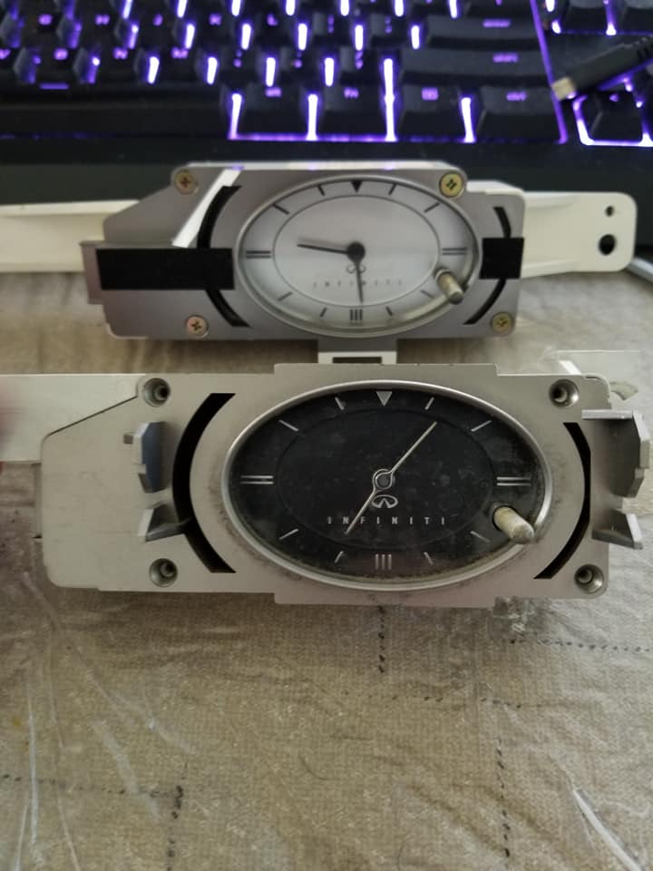
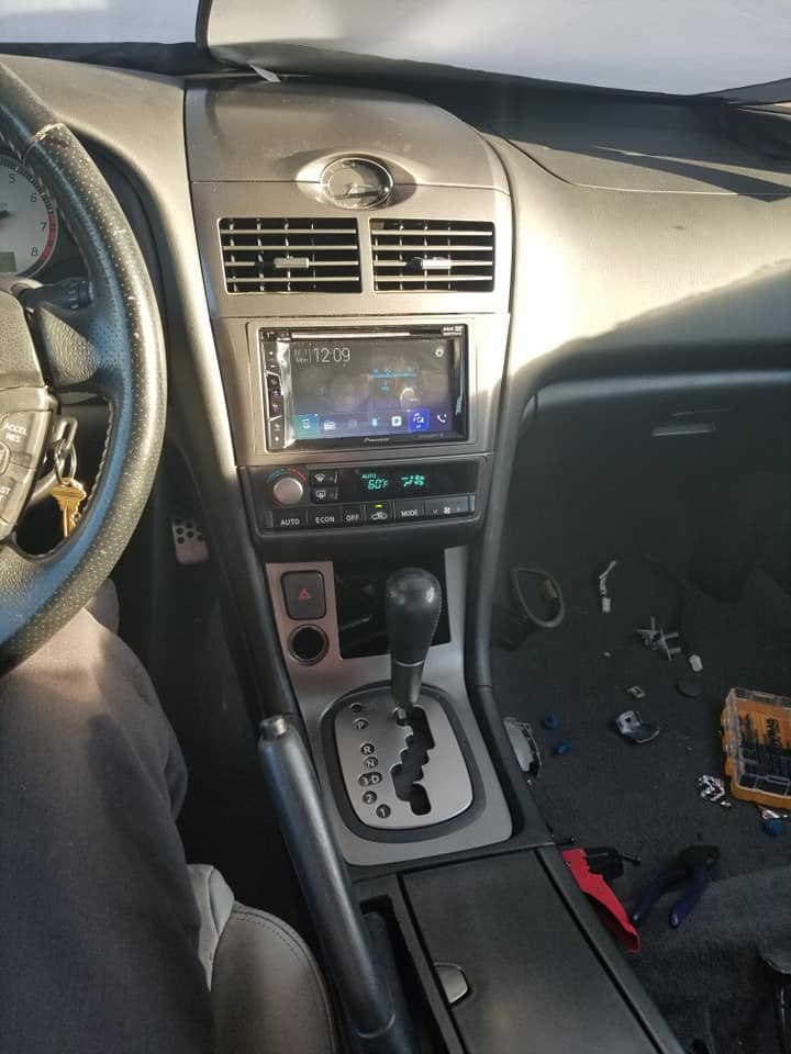
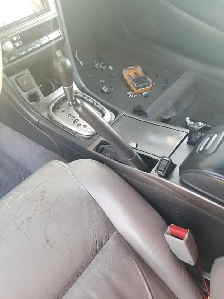
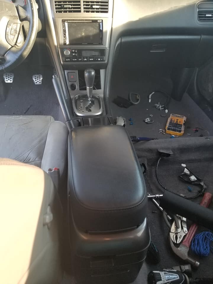
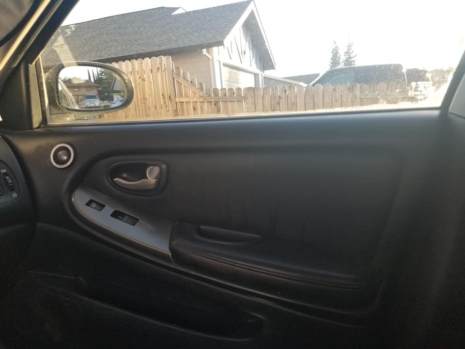
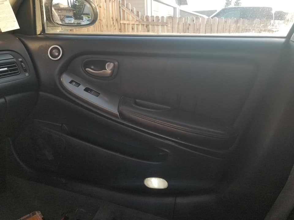
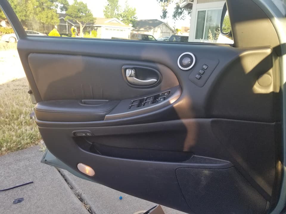
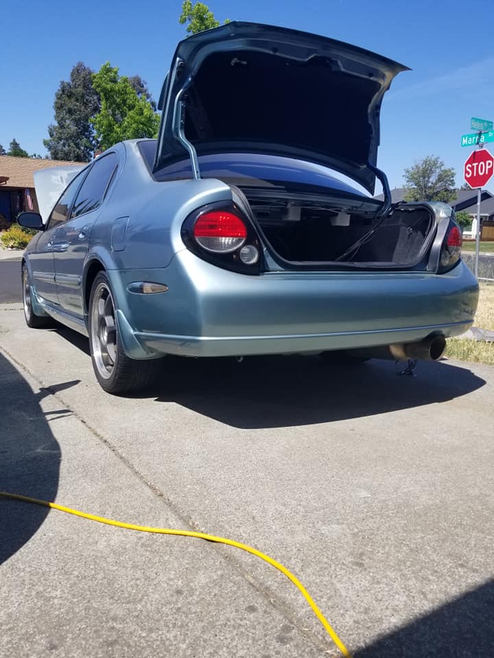
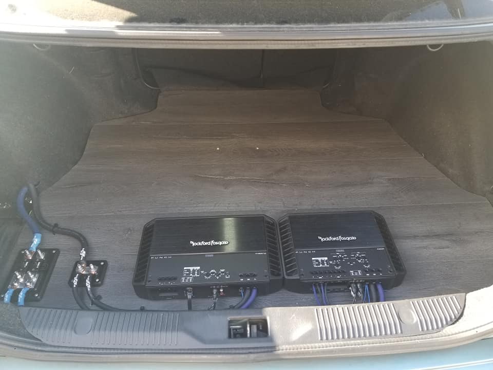
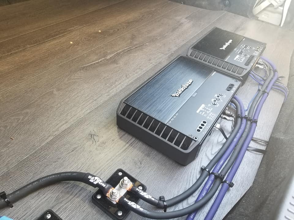
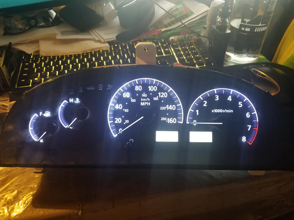
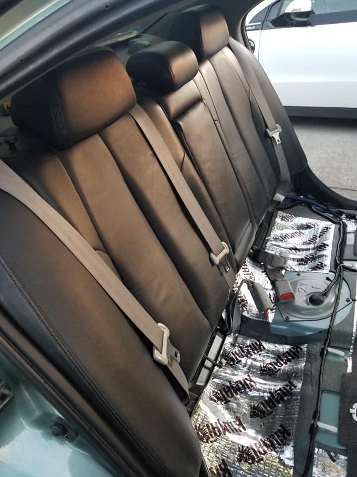
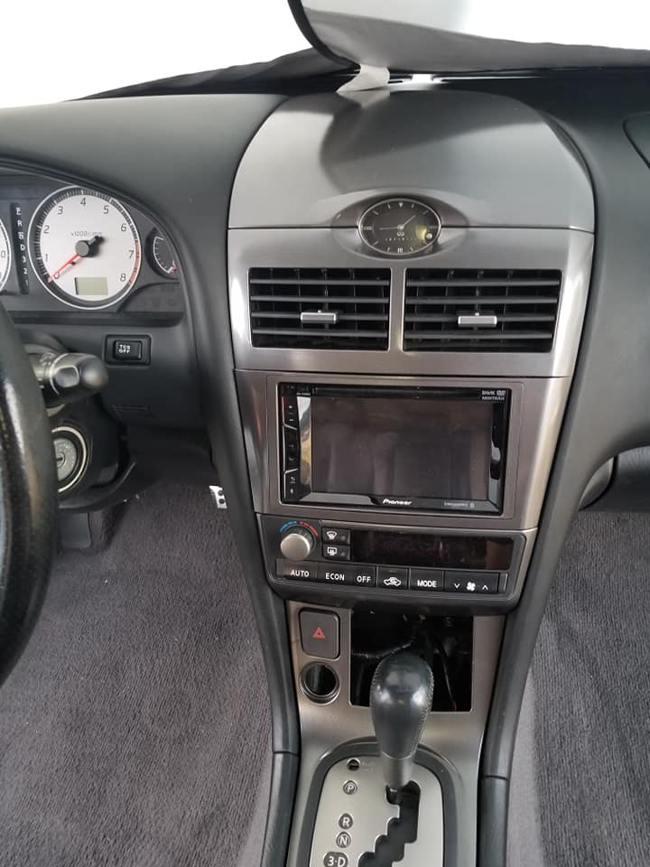
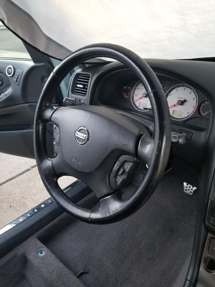
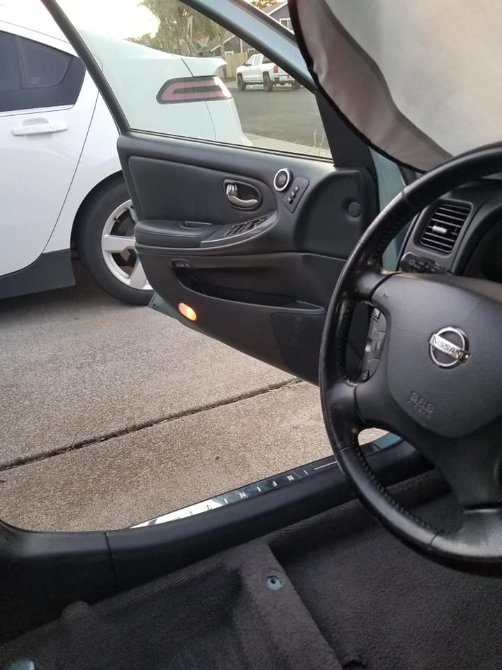
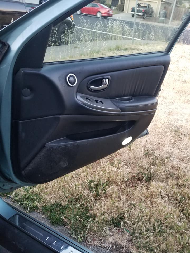
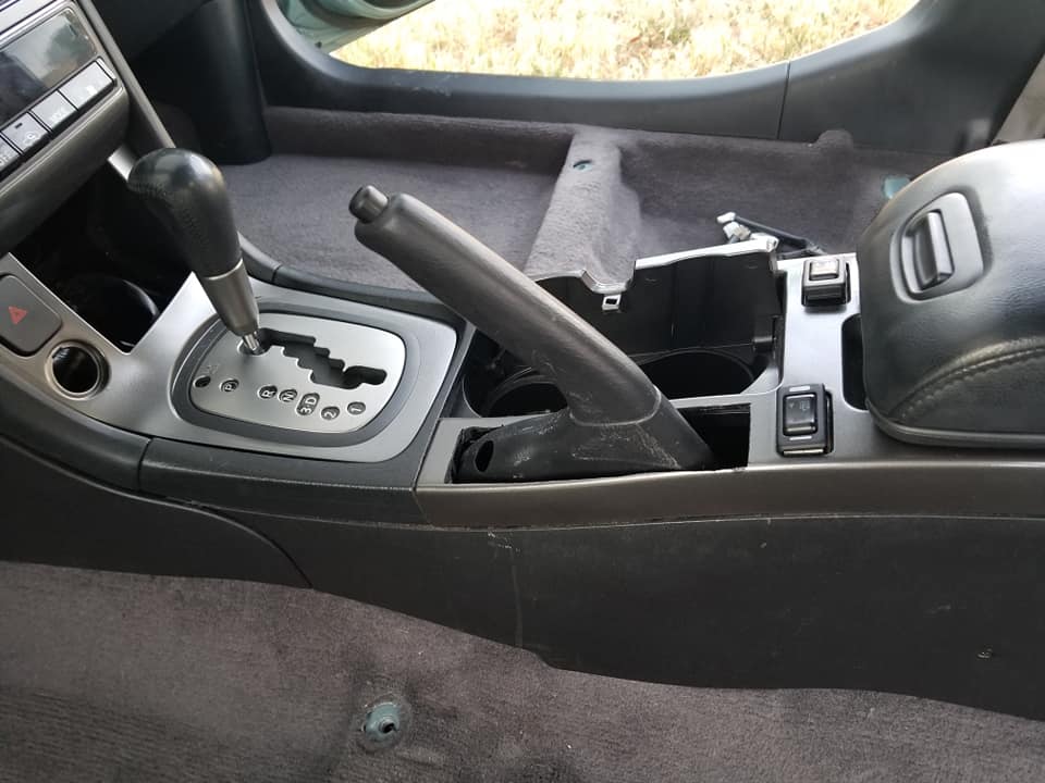
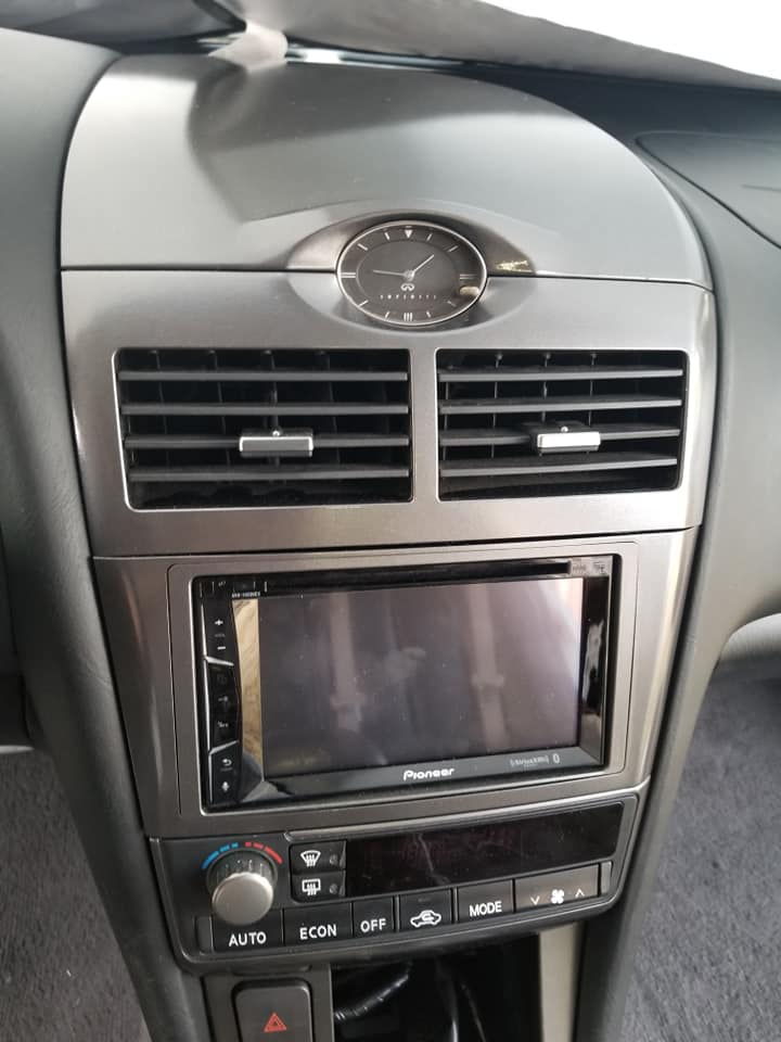
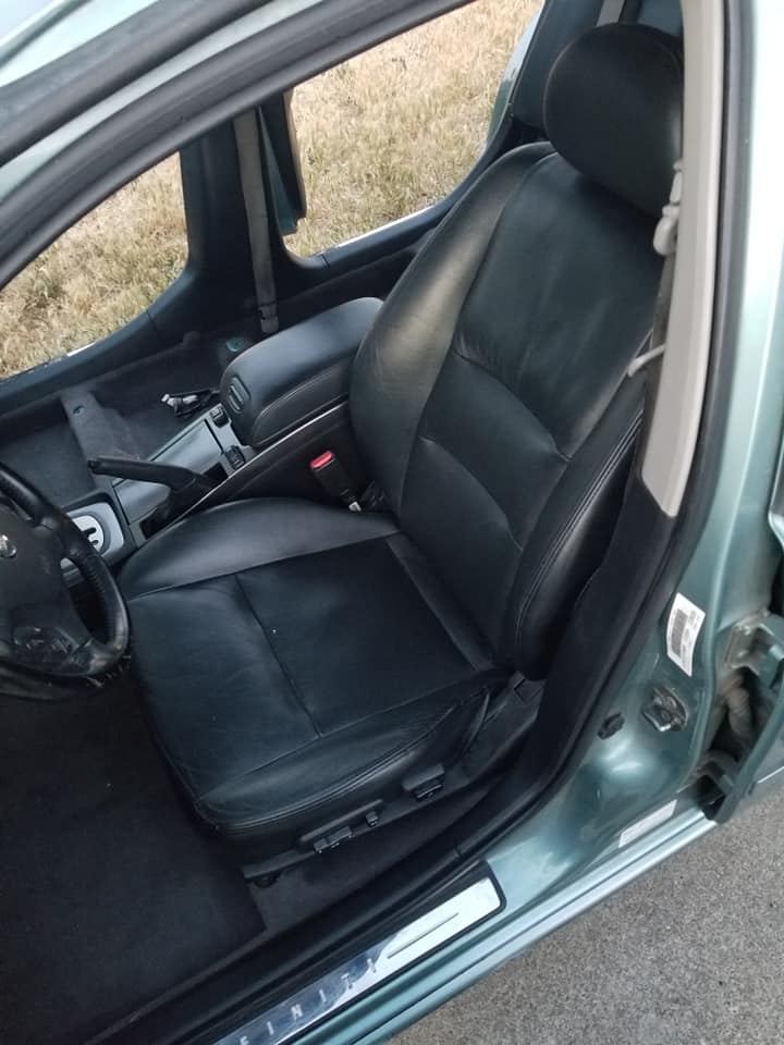
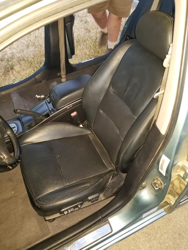
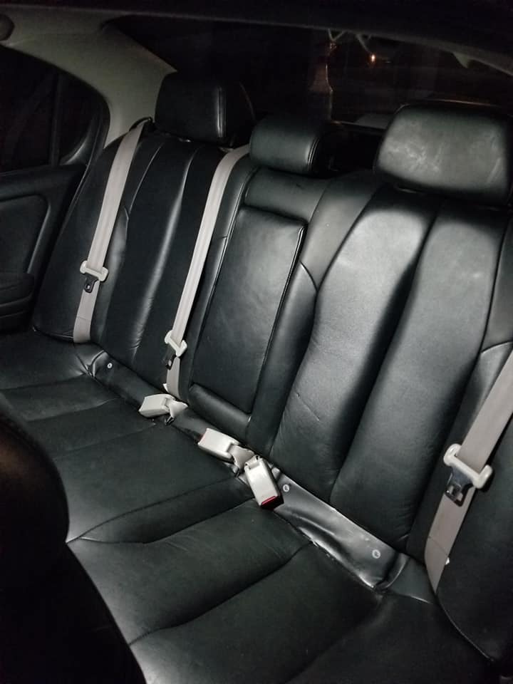
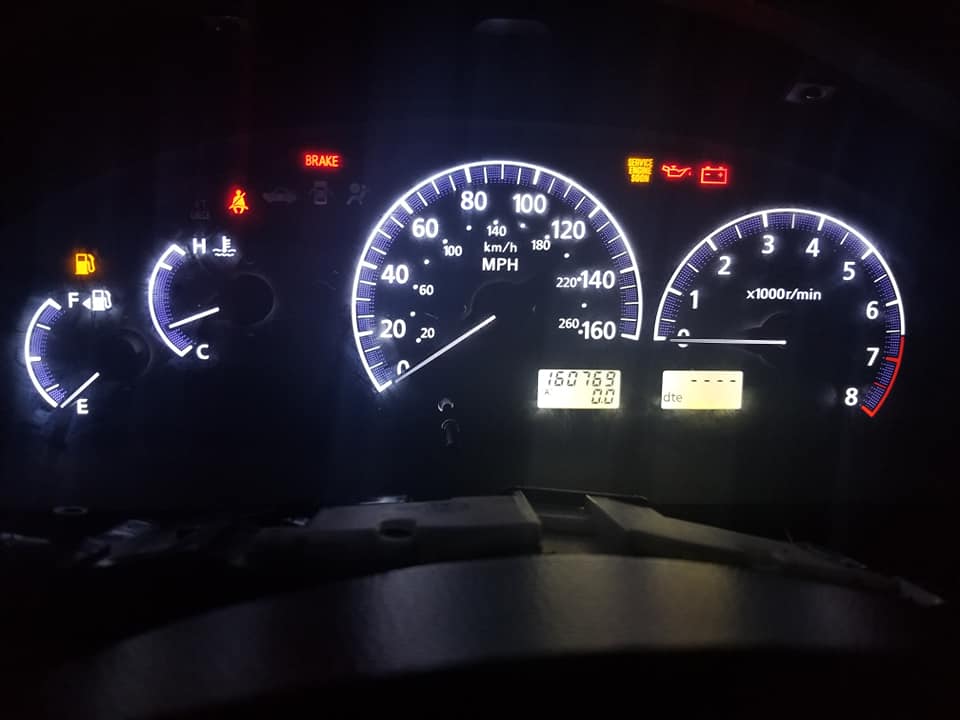
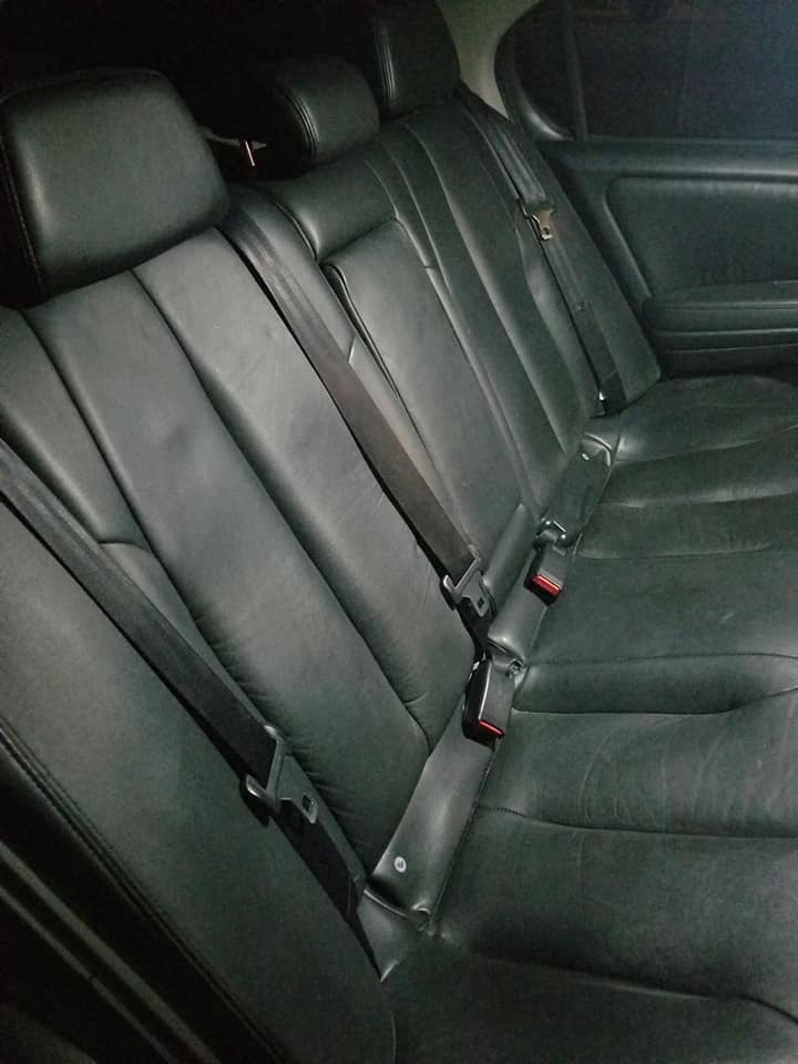
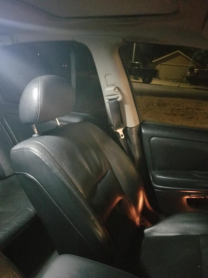



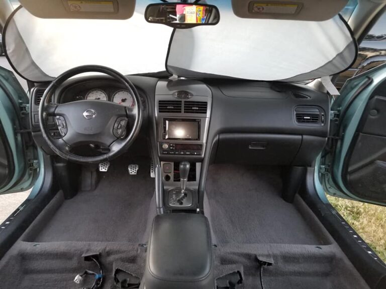
Community Member Credit: Eddy
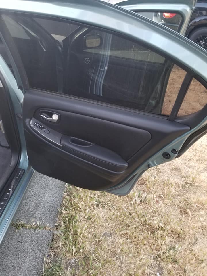
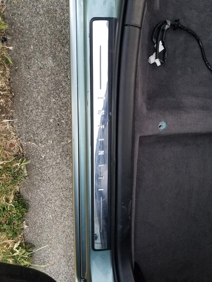
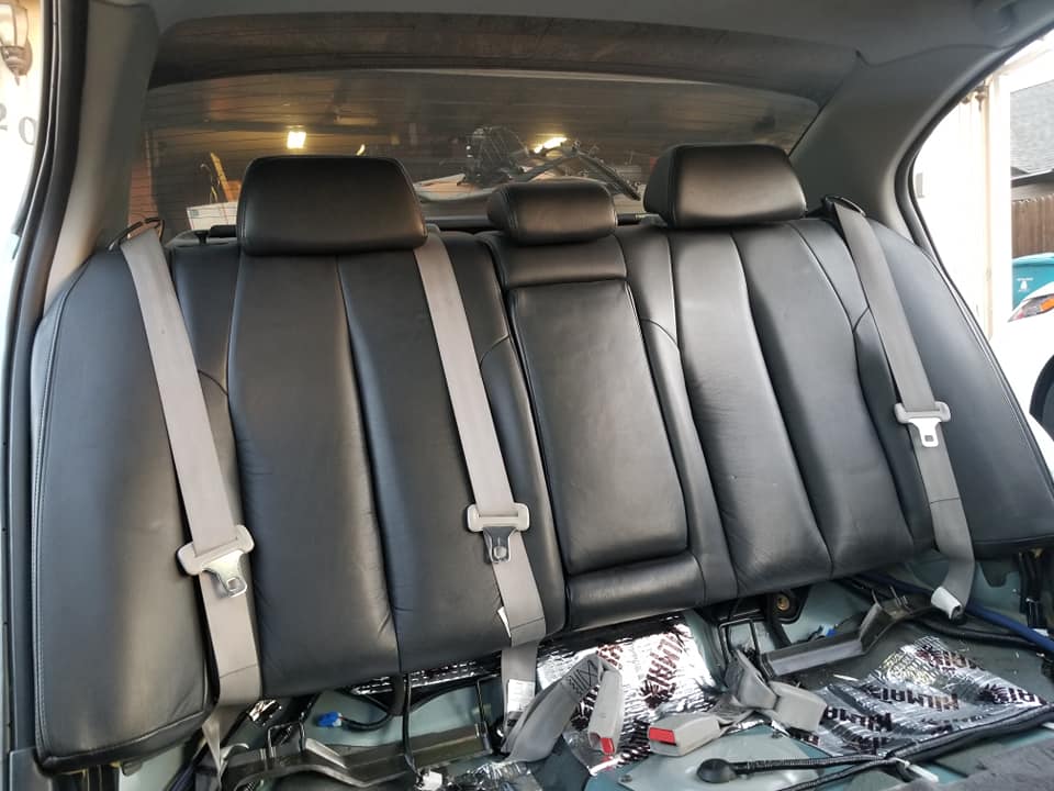
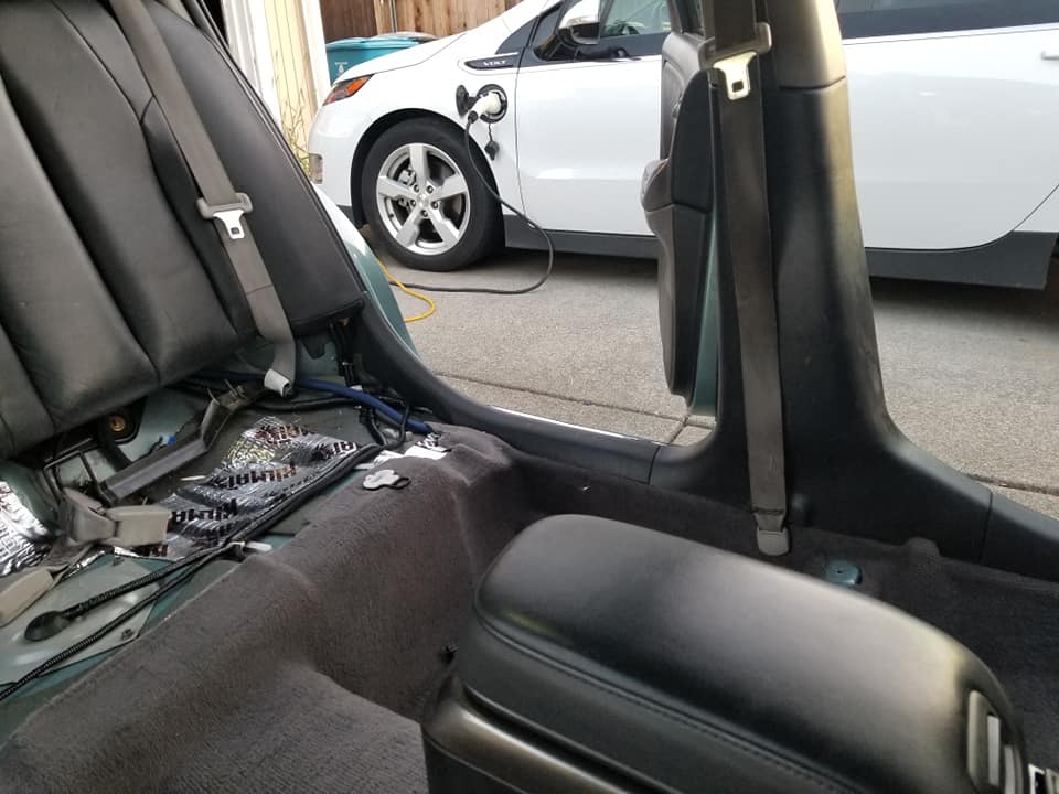
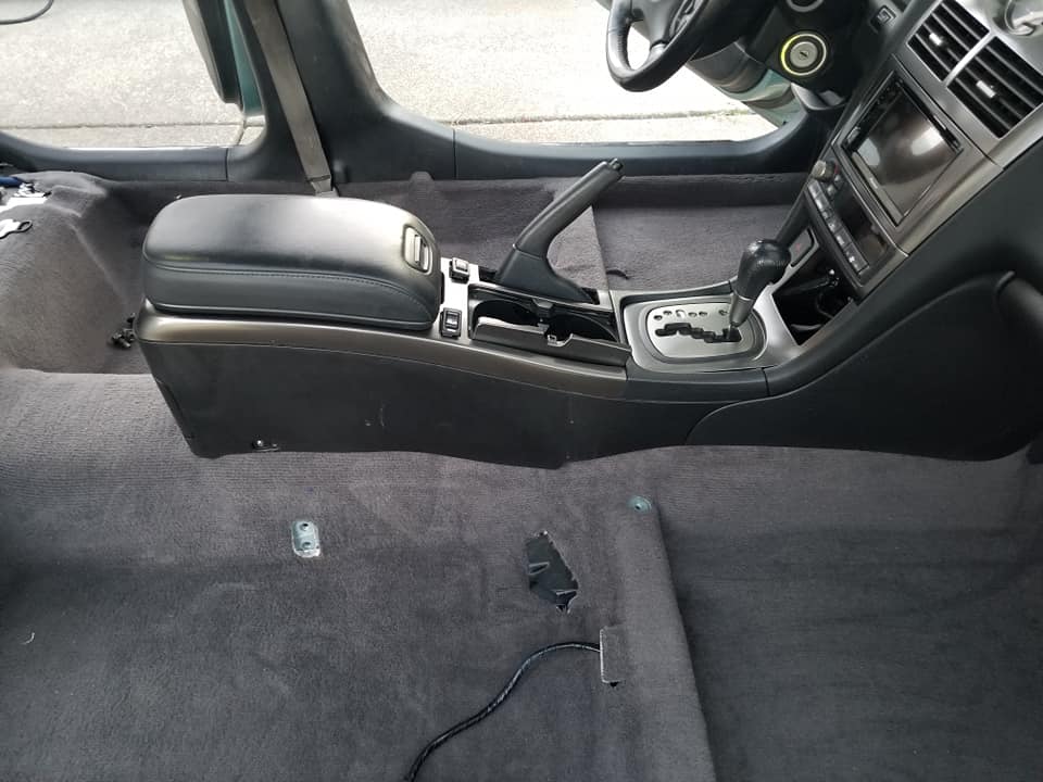
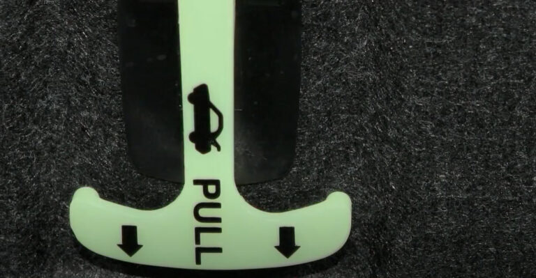
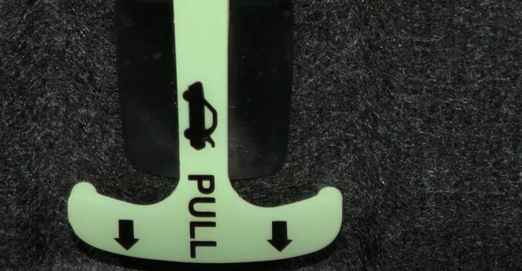
If you are having issues opening your trunk, you can use the emergency inside trunk release lever. It glows in the dark so you can easily find it.

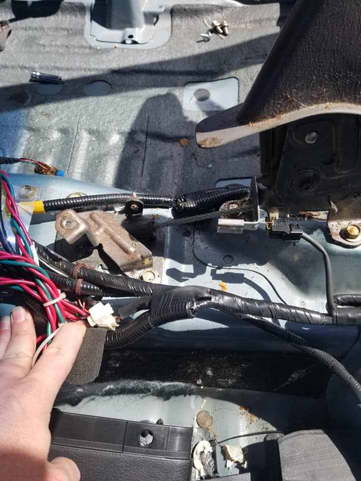
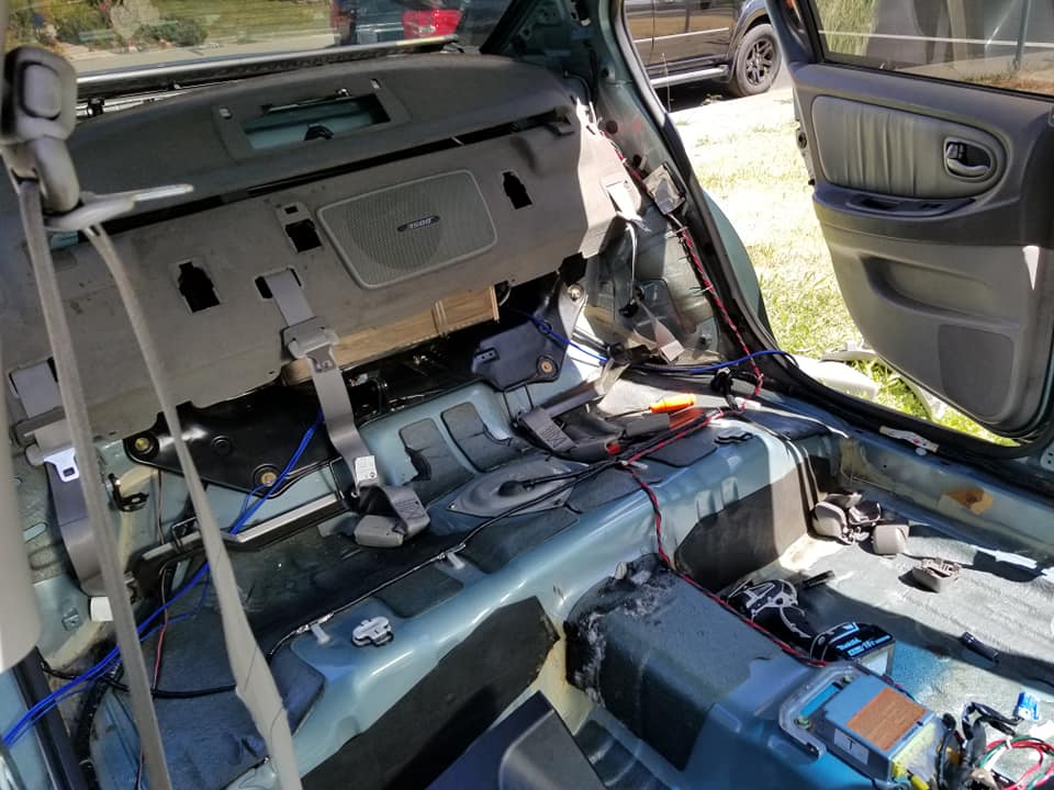
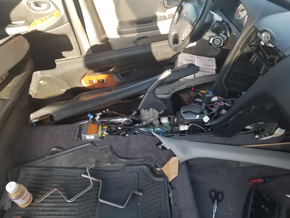
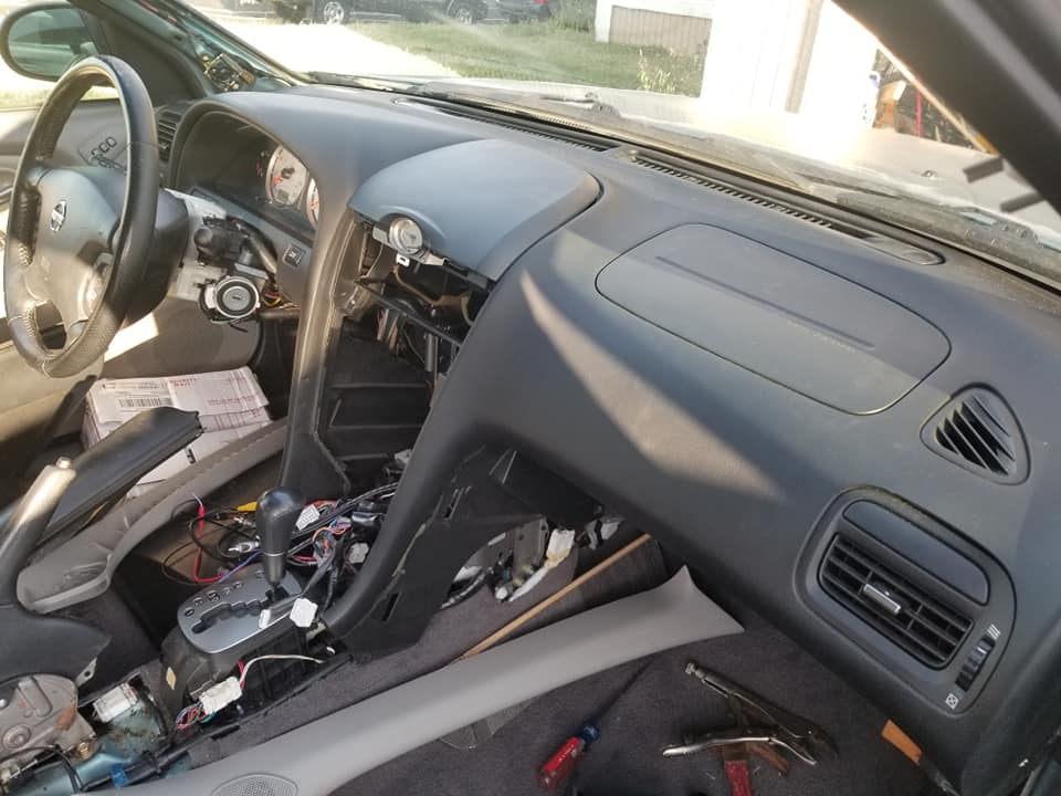
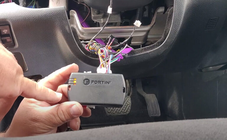
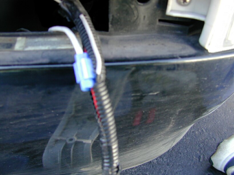
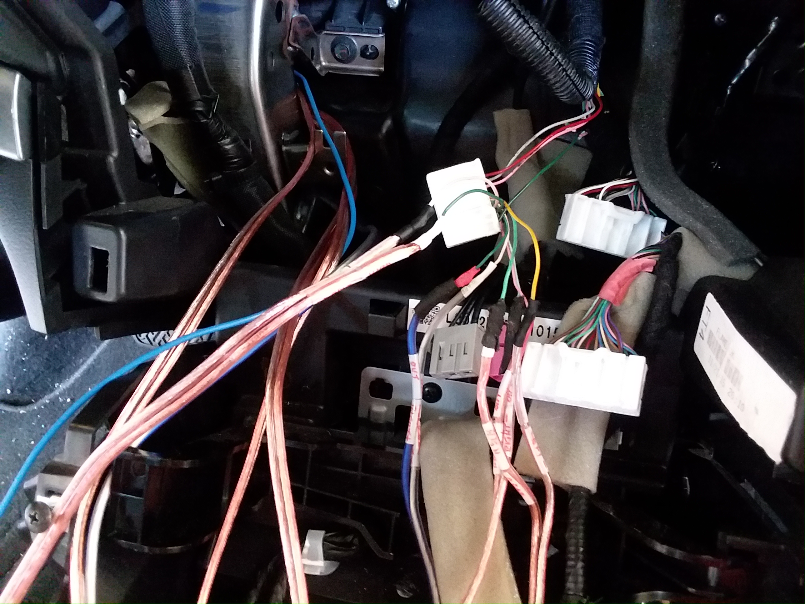
You can try checking the wires shown below to see if any are broken. Many owners have resolved their issues by re-splicing any broken wires. This appears to be a common issue.


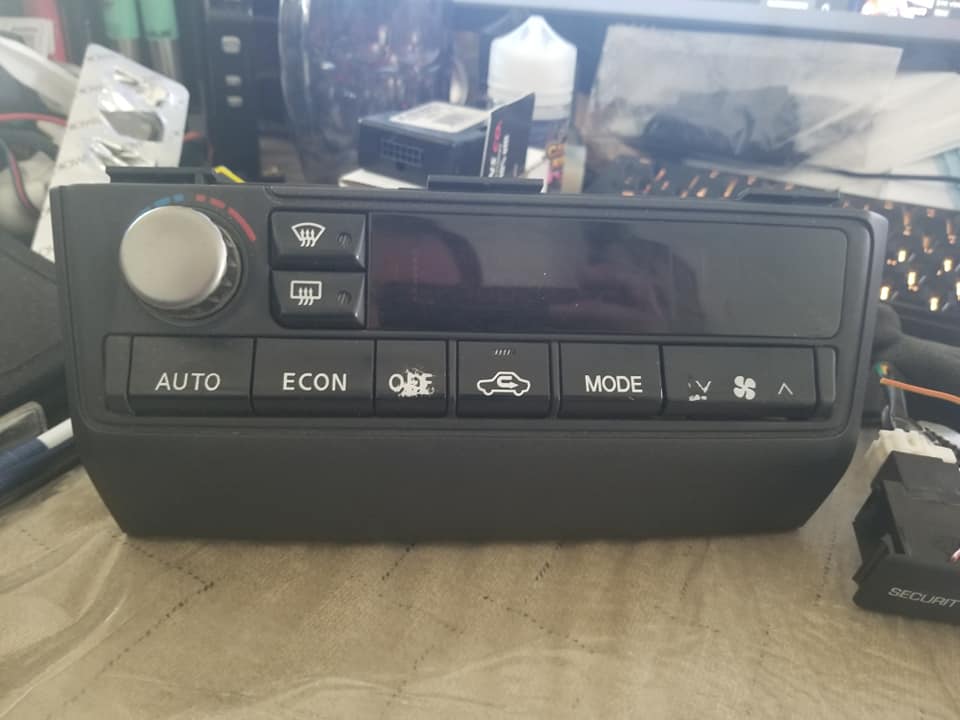
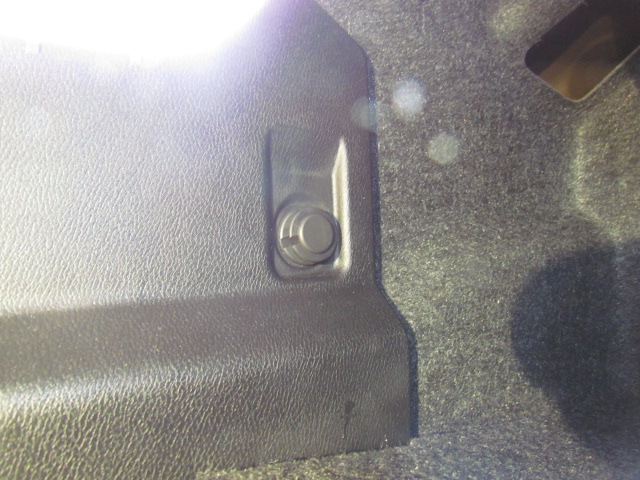
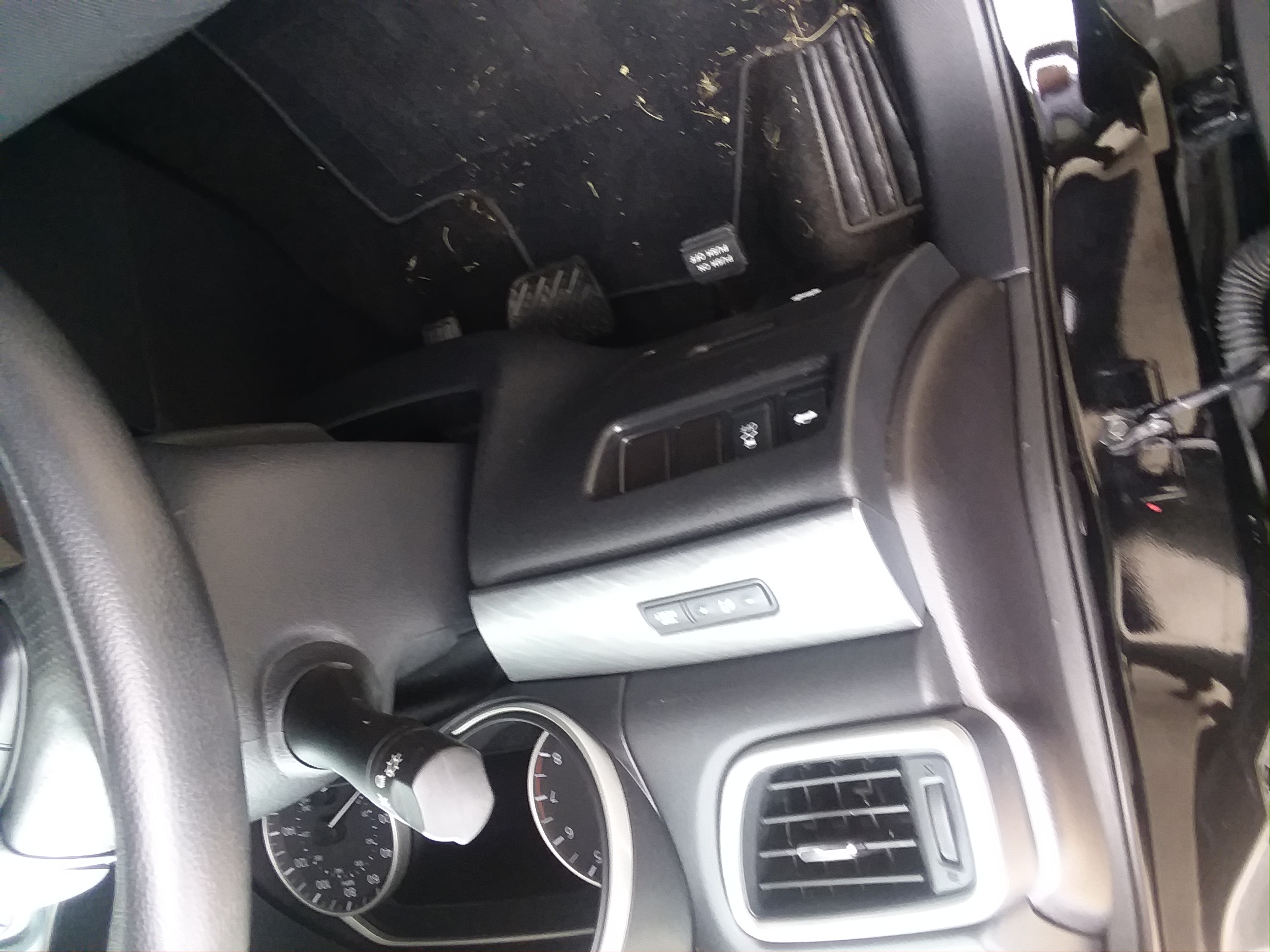
You can also try to check this button as well.

Community Member Credit: Candelario Amaya Jr.
This video shows how to install Fortin Evo NIST1 into a Maxima from 2009-2014 that has push to start. This is how to use OEM key fob by pushing LOCK 3X to remote start the vehicle. Hope this helps and encourages you to keep upgrading,
Install Instructions: Fortin Evo
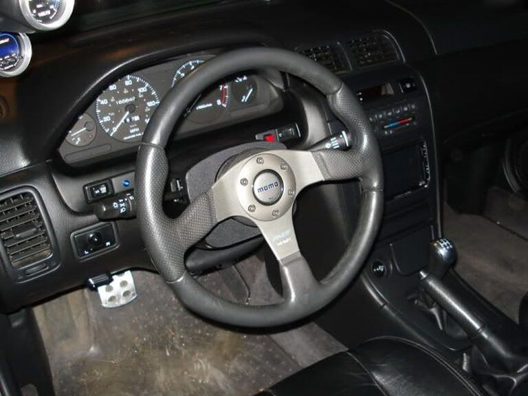
Community Member Credit: DJ420
Momo Race Lightweight Steering Wheel
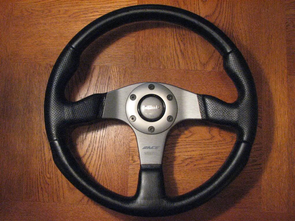
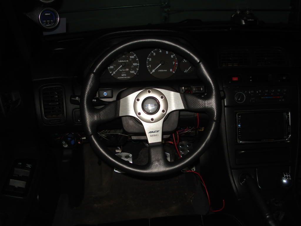
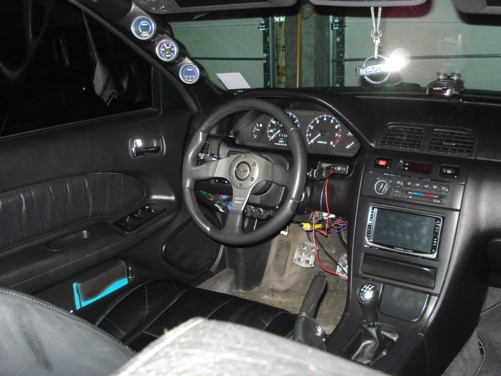
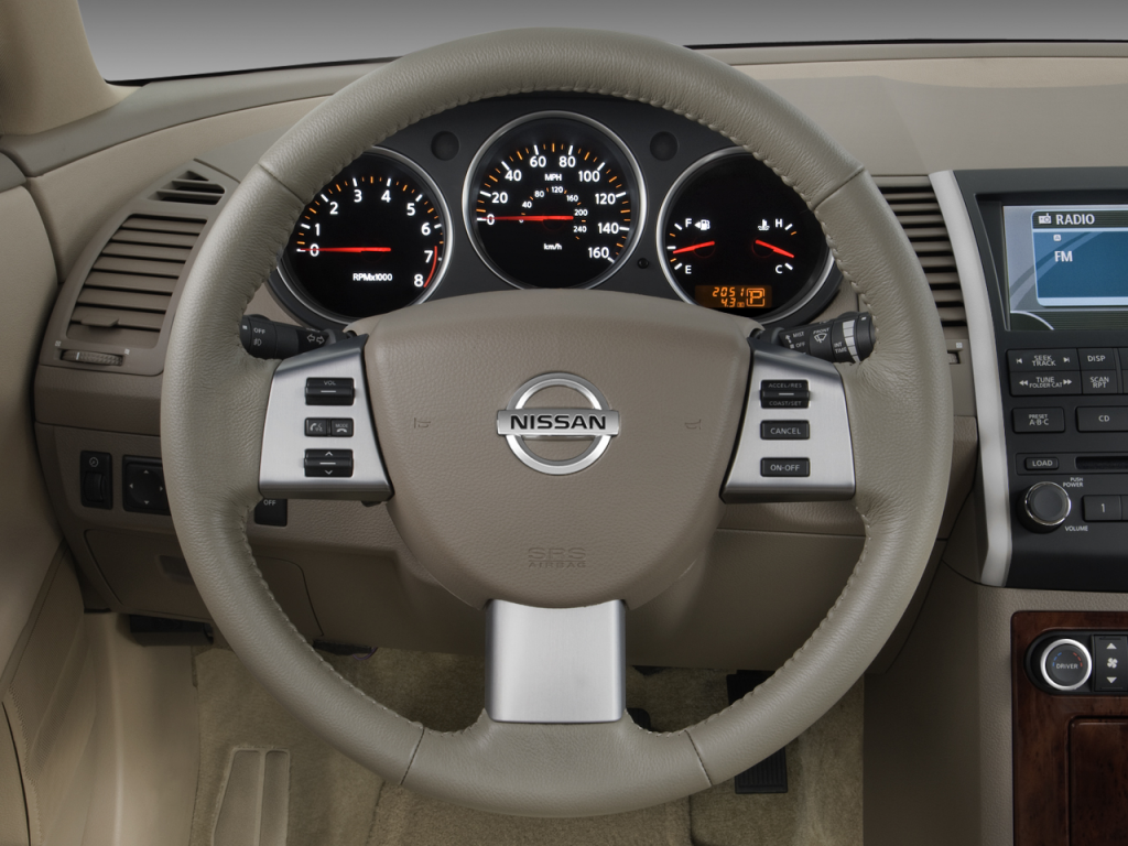
Here you will find the tools and items necessary to make a cruise control and horn sub-harness. I want the BAG to be the ONLY option deleted.
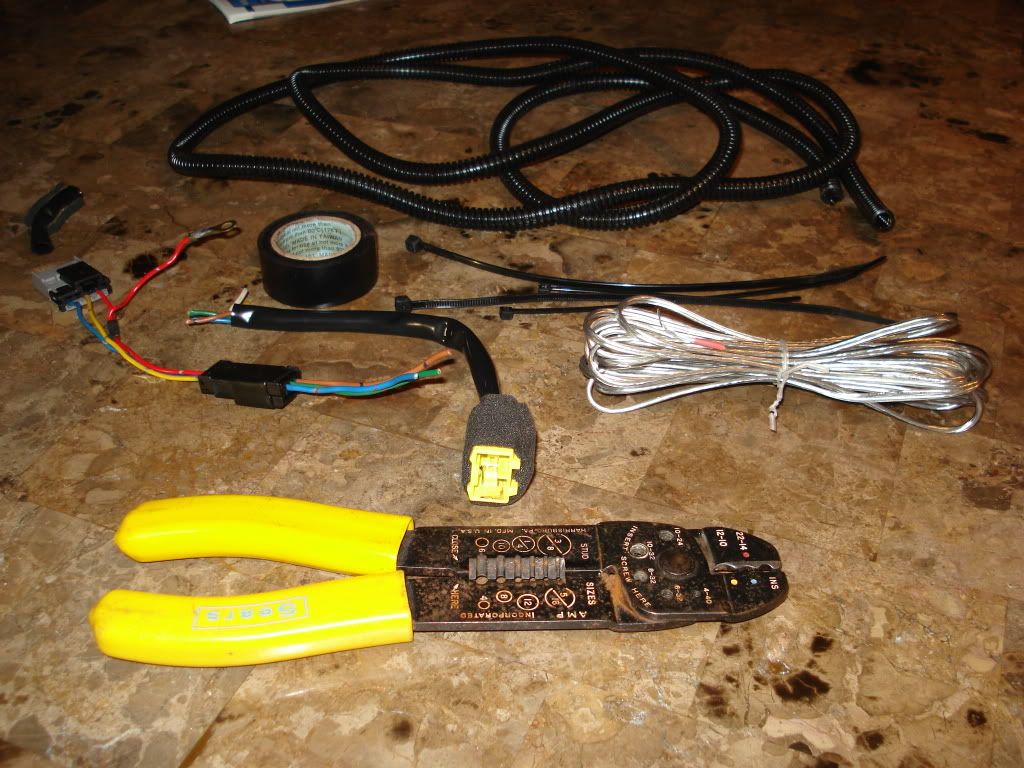
The 2 harnesses you see above are the harness going into the clockspring, and coming out of it. Simply put, your cruise controls and horn are wired through your clockspring. I have eliminated the clockspring, so I needed to make this to run the horn and cruise controls to another location.
Cut (or cap off) the yellow and white wires. These are the airbag wires and are no longer needed. Splice the brown, blue, and green wires together with their mate color on the other small harness end. I opted to add 5 feet of wire in between, to make the completed harness about 6 feet long. This will allow me to mount the controls just about anywhere!
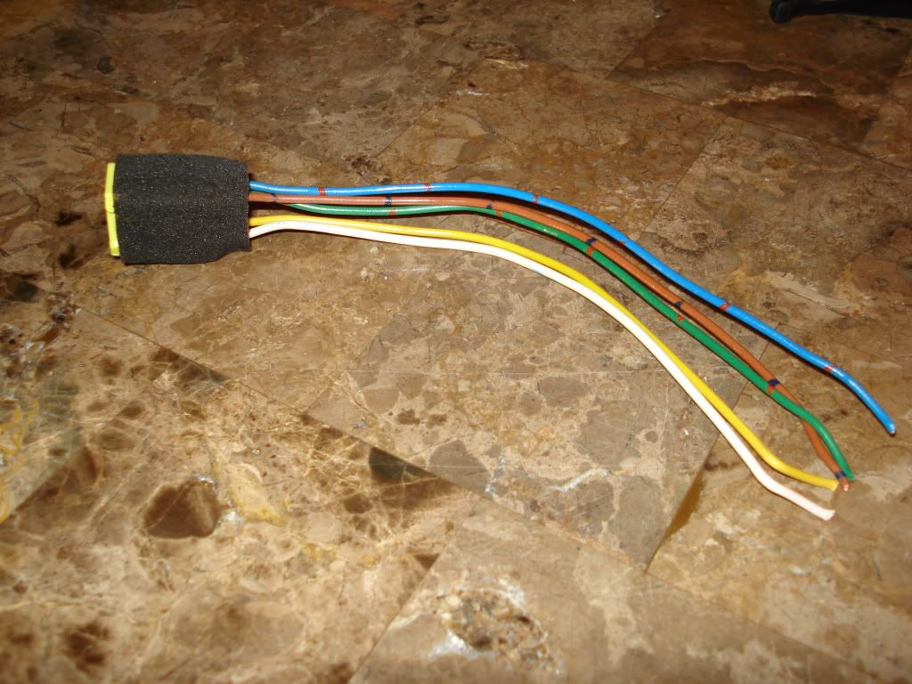
This is what my finished harness looks like!
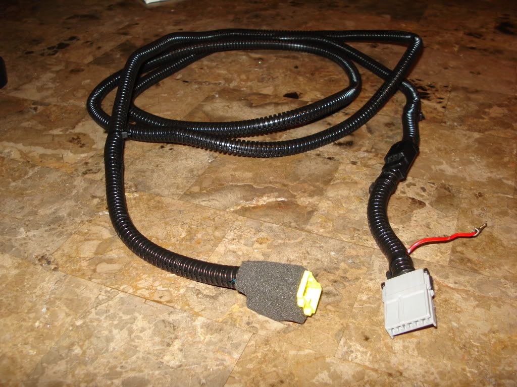
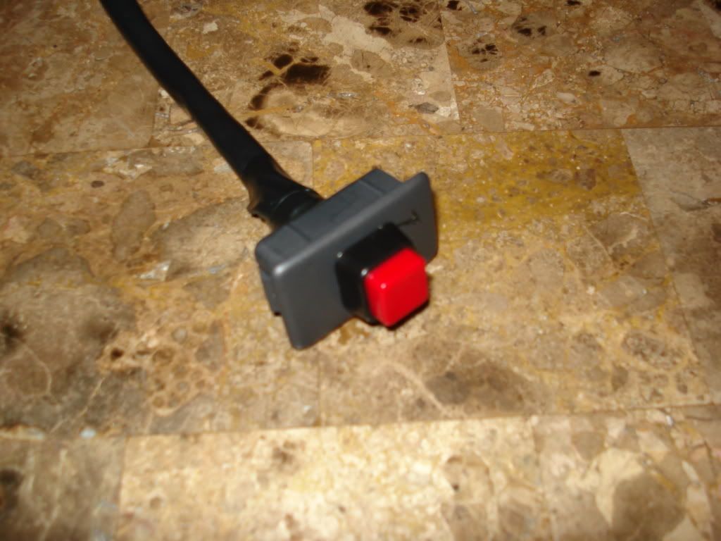
Push-button horn switch. Mounted on switch dead panel. Going to be mounted where the red and white wires are sticking out of my dash in the above pics of the wheel.
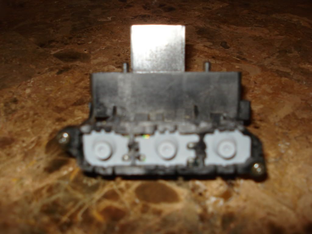
Here is a modified cruise control button.
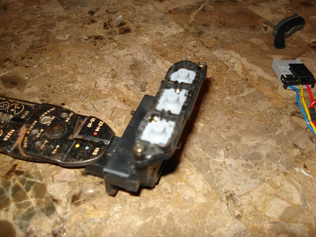
Due to the fact that there is a circuit board in the unit, it can not be changed to just singular push buttons. So I took off the bulky buttons, and cut back the housing so that just the rubbery buttons were accessible.
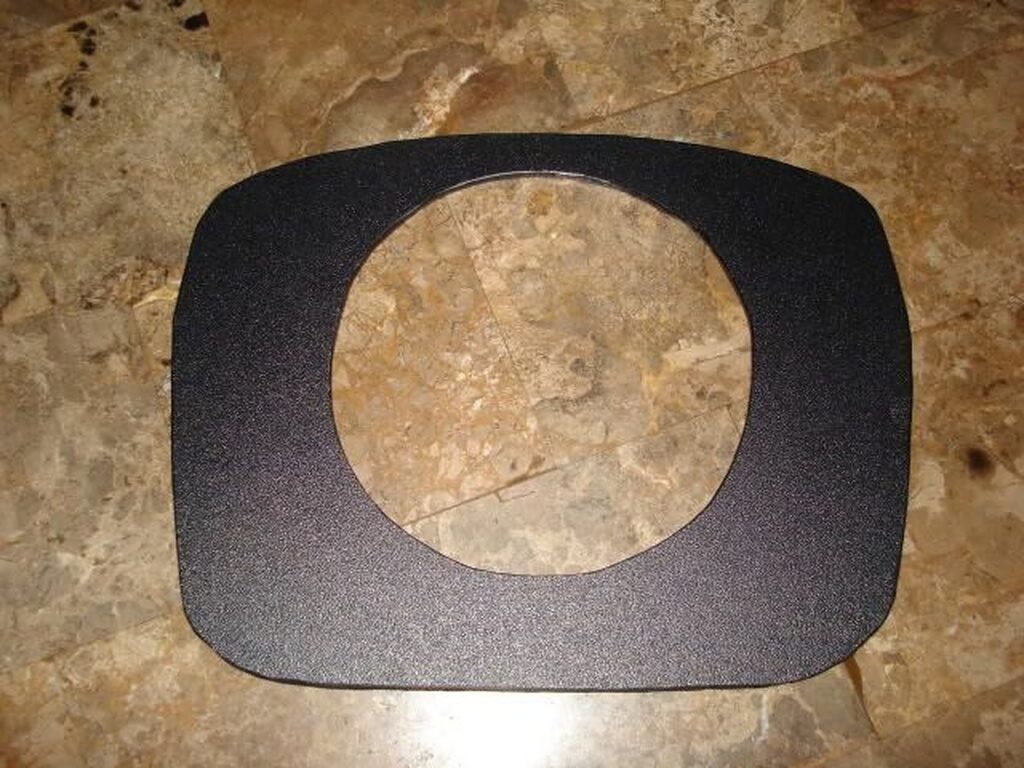
So this is what the final custom trim piece looks like. Took about 14 hours of work! Messed up the first one.
This is what it looked like BEFORE the trim piece is attached: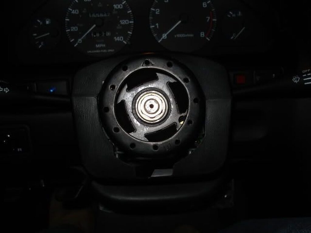 Here it is, trim attached to the column cover.
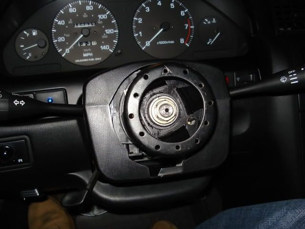
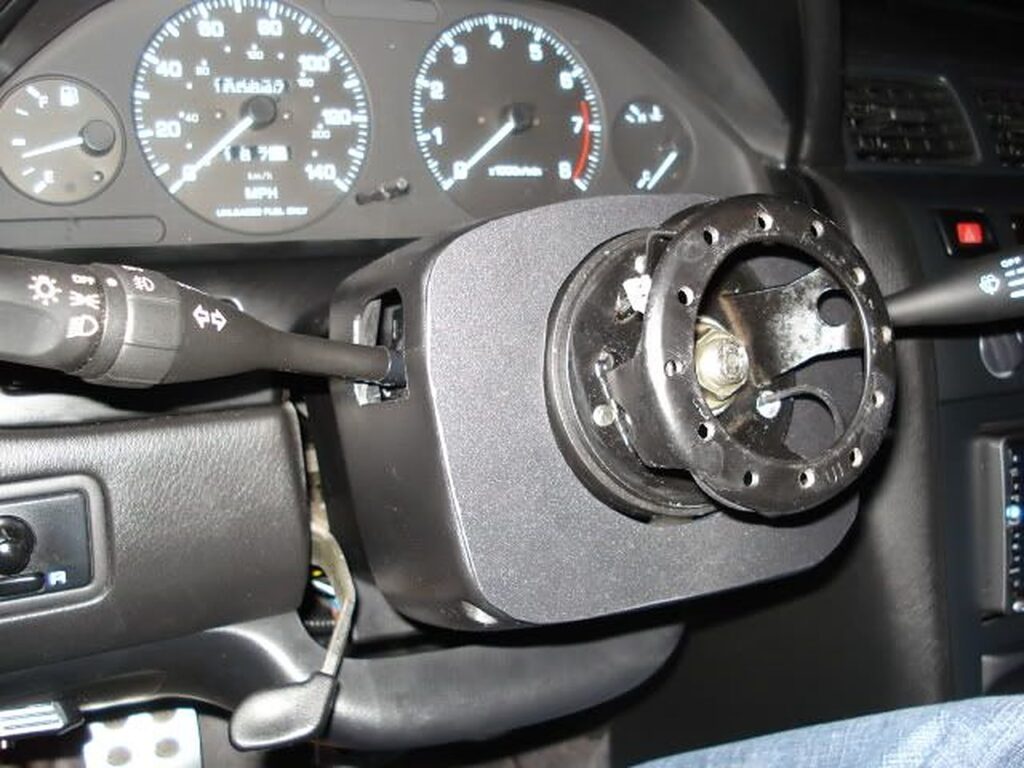
Here are a couple of shots after the wheel is back on. The horn button can be seen just beyond the wheel.. (hint: the red button! lol) I wanted black, but couldn’t find any in that shape and size.
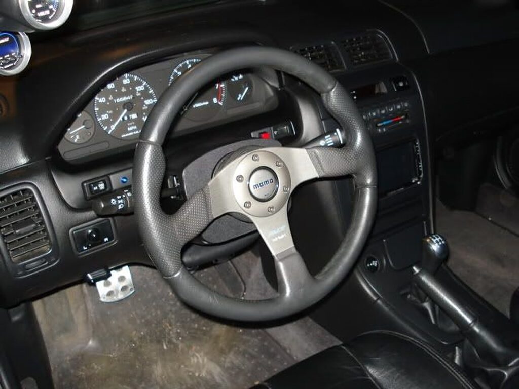
And last but not least, we have cruise controls. They aren’t permanently mounted, but the extremely ODD shape of the switch actually helped hold it where it is! lol
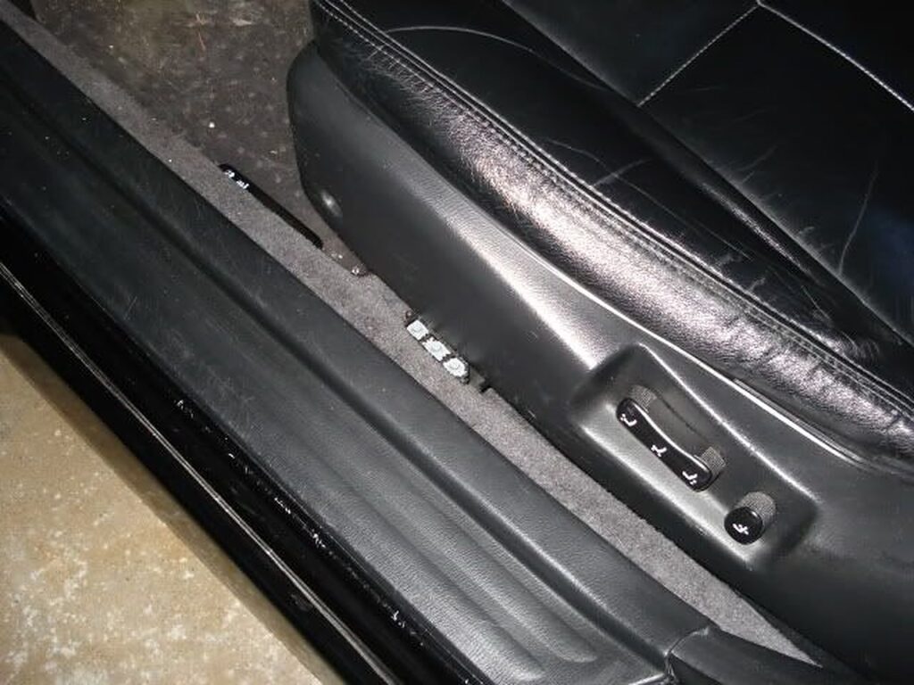
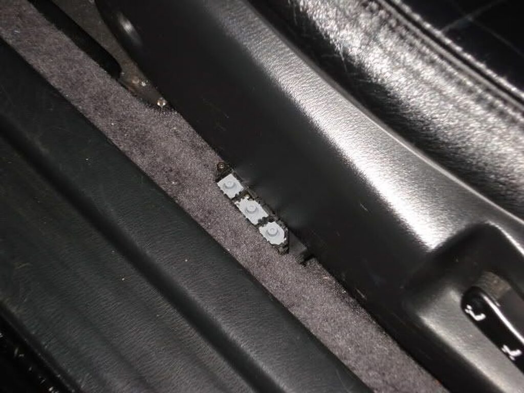
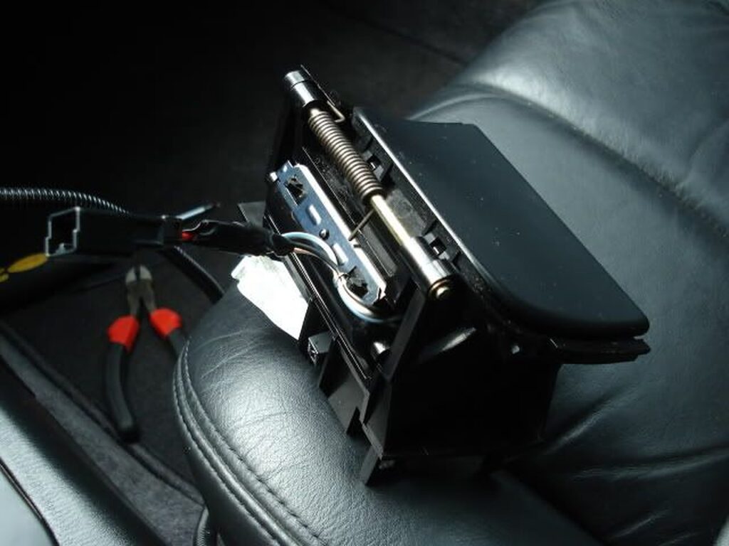
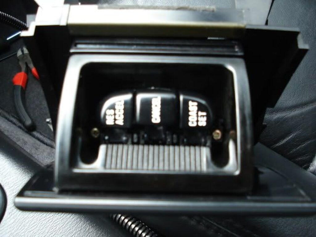
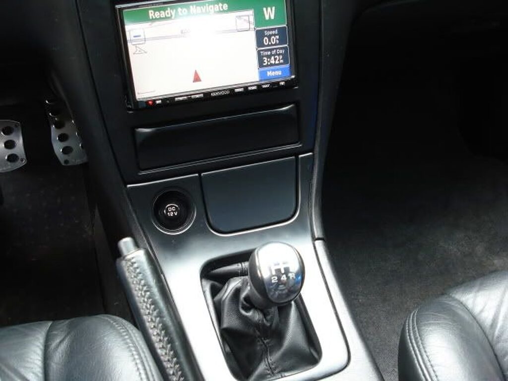
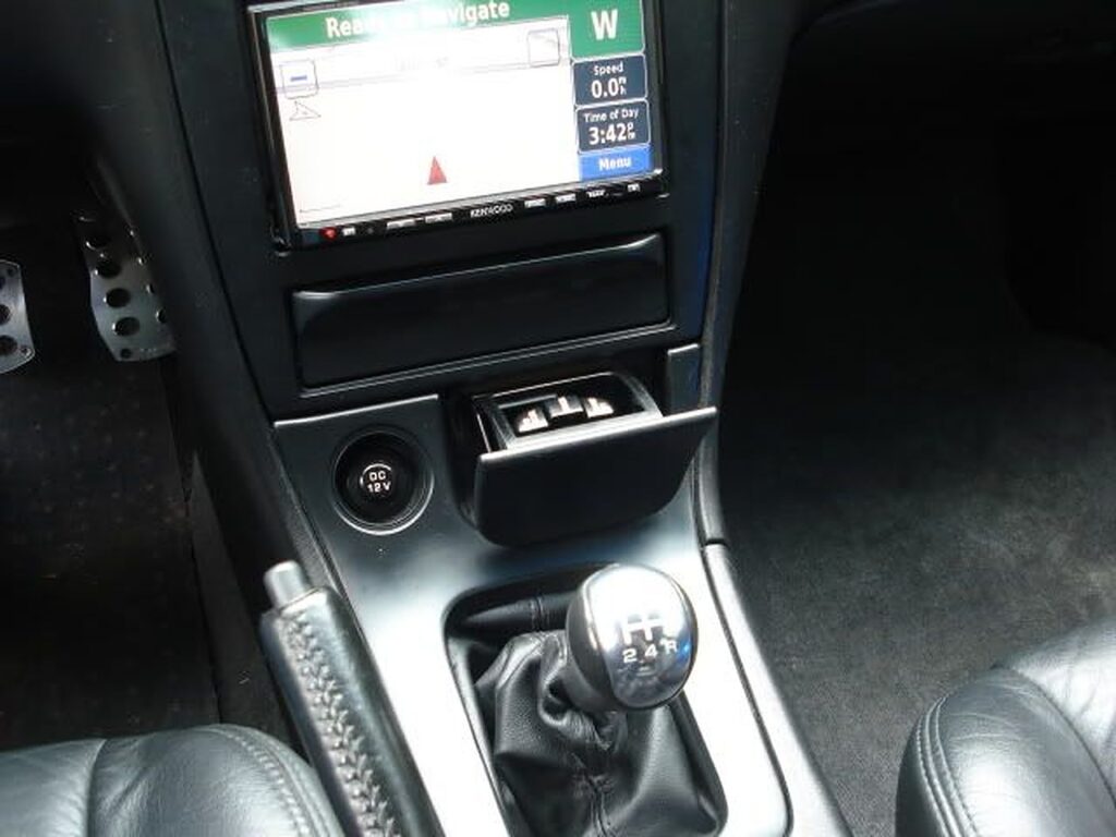
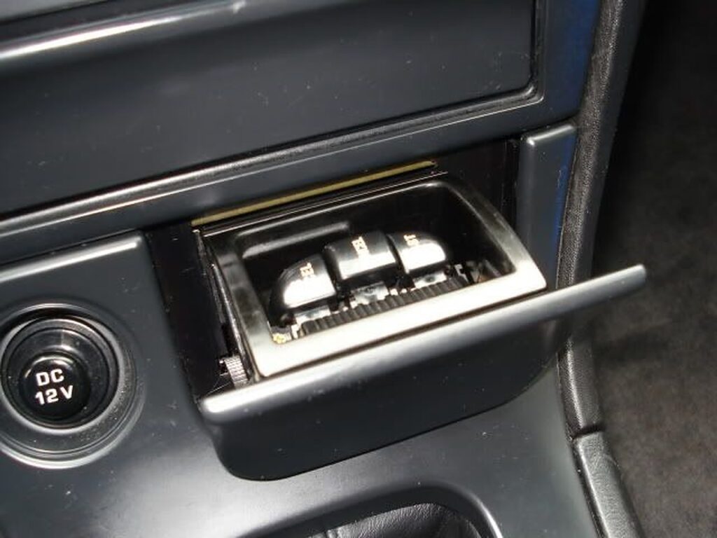
So, after relocating the cruise controls to the floor, I was happy to not have lost them. BUT, I wasn’t very happy with the appearance of them right by the door! I knew it was temporary because there was NO WAY I was gonna deal with that uncleanliness!! SO, in the background, I have been working on a lil project.
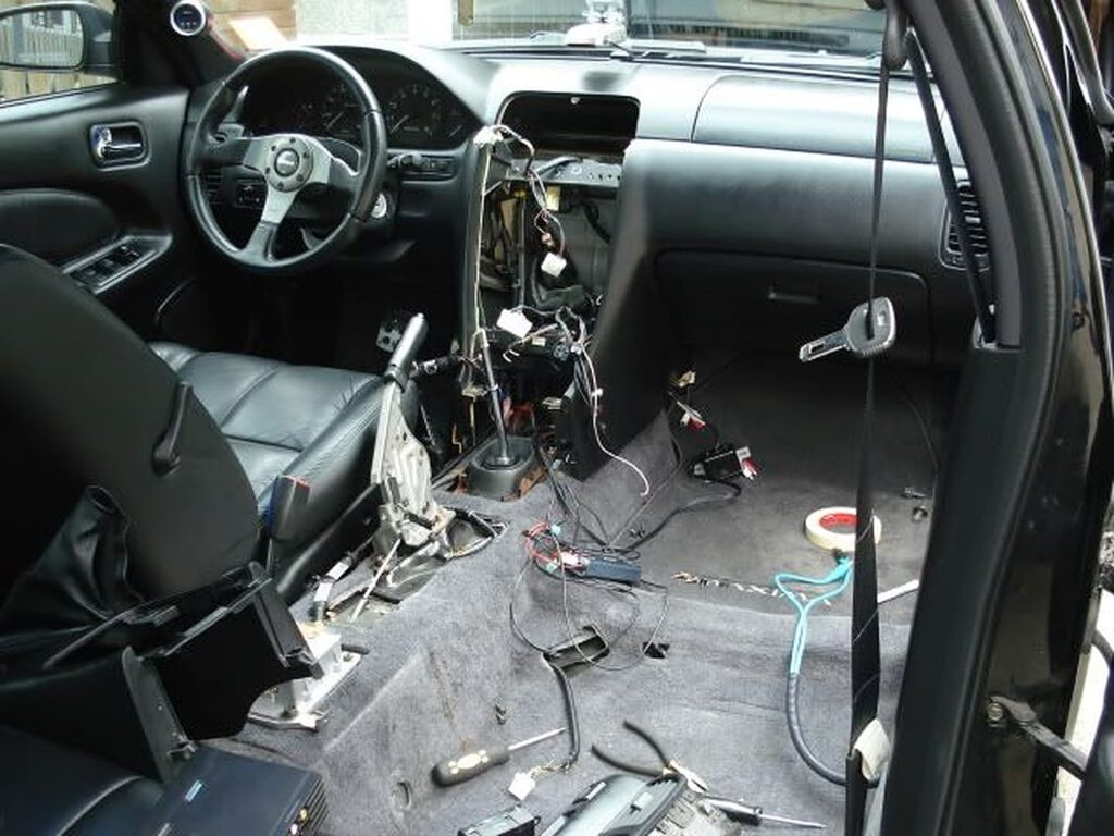
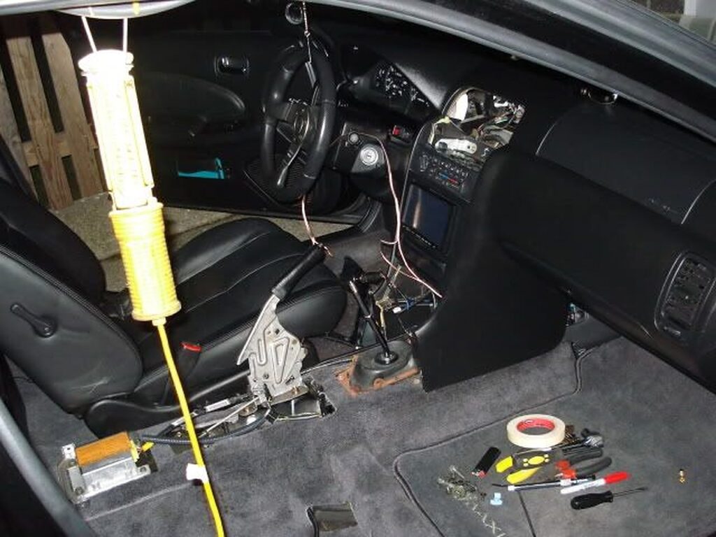 And so, without further ado, I bring to you Retractable Ashtray Mounted Cruise Controls!
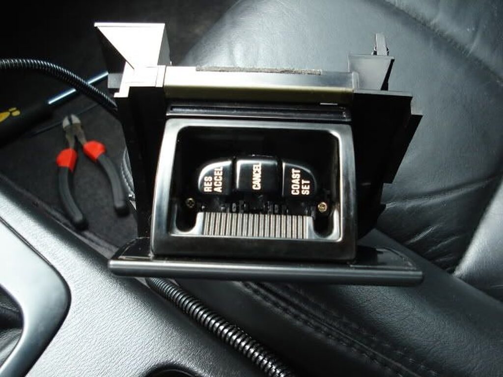
Member Credit: KZ 259
If your steering is worn-out and you would like to replace it, the following how-to will help you achieve that. Very simple to do.
Step 1: Disconnect the battery
Step 2: Unscrew this 10MM nut and one more on the opposite side.

Step 3: The airbag will now be able to come off, but be careful and be slow. If you man-handle the airbag, it can possibly knock you in the face. There are two connectors attached to the airbag. Disconnect the two wires as shown.

Step 4: You will need this tool to complete the job. This can be either bought or rented from any of the big 3 auto chain stores. Under $30 bucks.

Step 5: Take off the center nut first. It will have some torque to it so don’t be afraid to give it some strength. After you take the center nut off, you will see two threads (marked by the white arrows). That is where you will place the two bolts that come in your puller kit.
After the puller kit is in place, just ratchet away and the steering wheel will pop off. When placing on the replacement wheel, you will see a notch in the center of the steering wheel and another small notch on the steering wheel thread. These notches need to be lined up when inserting the new steering wheel or your steering wheel will be crooked.


DONE! And that is it for this DIY. Tit’s simple and straight forward. If you are doing this for the first time, it should not exceed longer than an hour.
Community Member Credit: D.Mason
Tools Needed:
Estimated time: 3 hours
Note: These were the best picture we could get on this one.
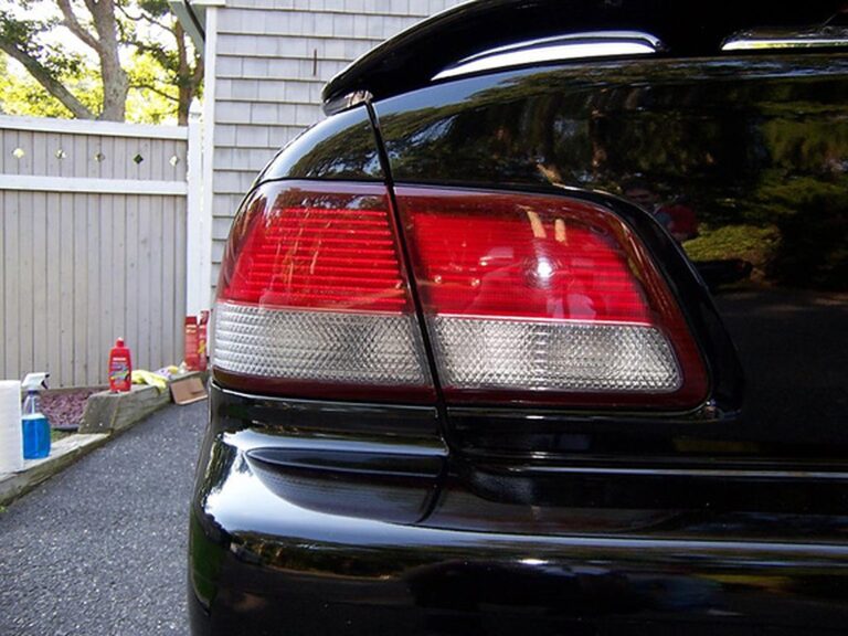
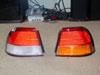
The first step in modifying your taillights is to remove the taillight from the vehicle. Begin by removing the interior lining in the trunk. Some of the tabs that hold the lining in require a flat head screwdriver while others come off with a Phillips screwdriver. There are 2 plugs that need to be unplugged from the tail light. They both have white connectors. There are also some plastic pieces that hold all of the wiring to the nut. These may be tough to yank off. I used a pair of pliers to pull them off. There are 4 8mm nuts that hold the taillight in. Remove these using an 8mm deep socket. The only thing holding the taillight is some black sticky adhesive. There are a few ways to get the taillight out. One method is to gently heat up the adhesive using the heat gun so that the adhesive softens. Then push on the taillight. Another way is to gently tap on the 4 studs that hold the taillight in the vehicle. Lastly you can push the taillight out of you are strong enough. Place the bottom of your palm on the flat part of the taillight and push hard! Be careful of the adhesive so that it does not get on your hands or the taillight.
1. Remove the 5 small black Phillips screws that are located around the taillight.
2. To separate the taillight lens from the housing you will need to heat up the glue that holds it together. It will most likely take at least two passes on each side of the taillight to get the glue warm enough.

3. Some heat guns only have a ‘low’ and ‘high’ setting. This particular one has 10 different setting. As you can see a setting of 8 was used. The key is to not overheat any one particular spot because it will melt the plastic housing or taillight lens.
4. Pick one side to begin with and hold the heat gun about 1″ away from the black housing. DO NOT HEAT UP THE TAILLIGHT LENS AT ALL! It will begin to fry like an egg. Heat up that spot for 7-10 seconds. Do this on every spot on this particular side of the taillight.
5. Working your way slowly around the tail will ensure no damage to the housing or lens. This is the most time consuming step in the entire process.
6. One you have gone around the taillight twice, it may be soft enough to pry open. Using a knife or some type of prying tool, try to pry on a corner of the taillight and see if it gives. If it does, slowly pry the tail light open until it separates from the lens. If the glue still seems cold, apply some more heat with the heat gun.
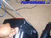
7. Be Careful of the lens beginning to separated.
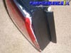
8. The lens is completely separated. Make sure that the glue does not stock to the outside of the lens. It’s quite messy.
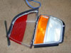
9. Use the knife or pry tool to remove the orange lens. Use some heat if necessary.
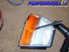
10. Cutting the acrylic lens can be a bit frustrating. Don’t let it get you down. Here are some tips on cutting the piece out. Some people use the orange and red lens and trace it out on the acrylic sheet. Others try to make a paper template that will fit in the taillight lens and then use that template to cut the acrylic. Some tools that can be used to cut the acrylic lens are a rotary tool, acrylic cutter, or a soldering iron.
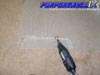
11. Once the lens is cut, you need to wedge it into the taillight lens. Use a bit of heat the curve the lens. Use very little heat or the lens will melt!
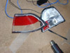
12. Removing the red lens is up to you. I chose to remove it. Some don’t. Your call. Simply remove the Phillips screw.
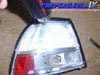
13. Once the new lens is in, you are ready to put the taillight back together. Reheat the glue until it is soft and then put the lens into the housing. Hold it tight for about 15-20 seconds so that it seals properly. Put the screws right back in so that it helps seal the taillight the way it originally was.
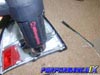
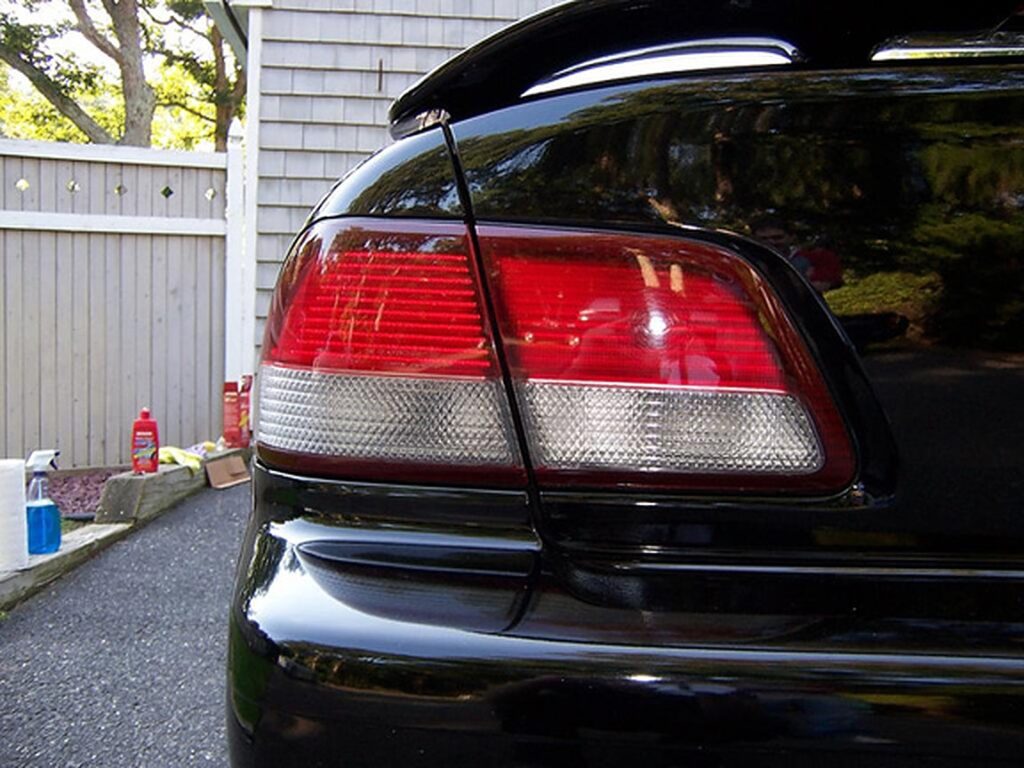
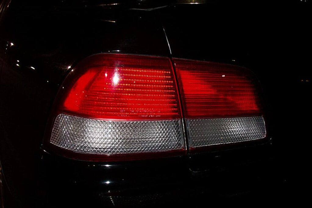
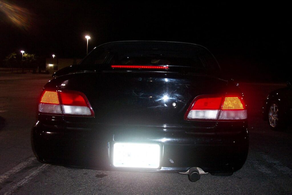
14. Isn’t that beautiful! One note. There is a size #194 wedge bulb behind where that small red lens was. That light is just a driving light that turns on with one turn on the light stalk. I chose to remove the bulb so that it wouldn’t show. Again, user discretion. Put the taillight back in and re-connect everything. Put back lining too!
Community Member Credit: gtr_rider
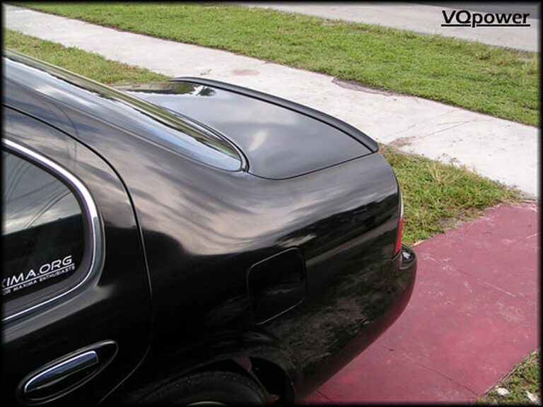
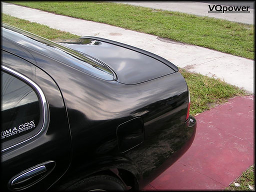
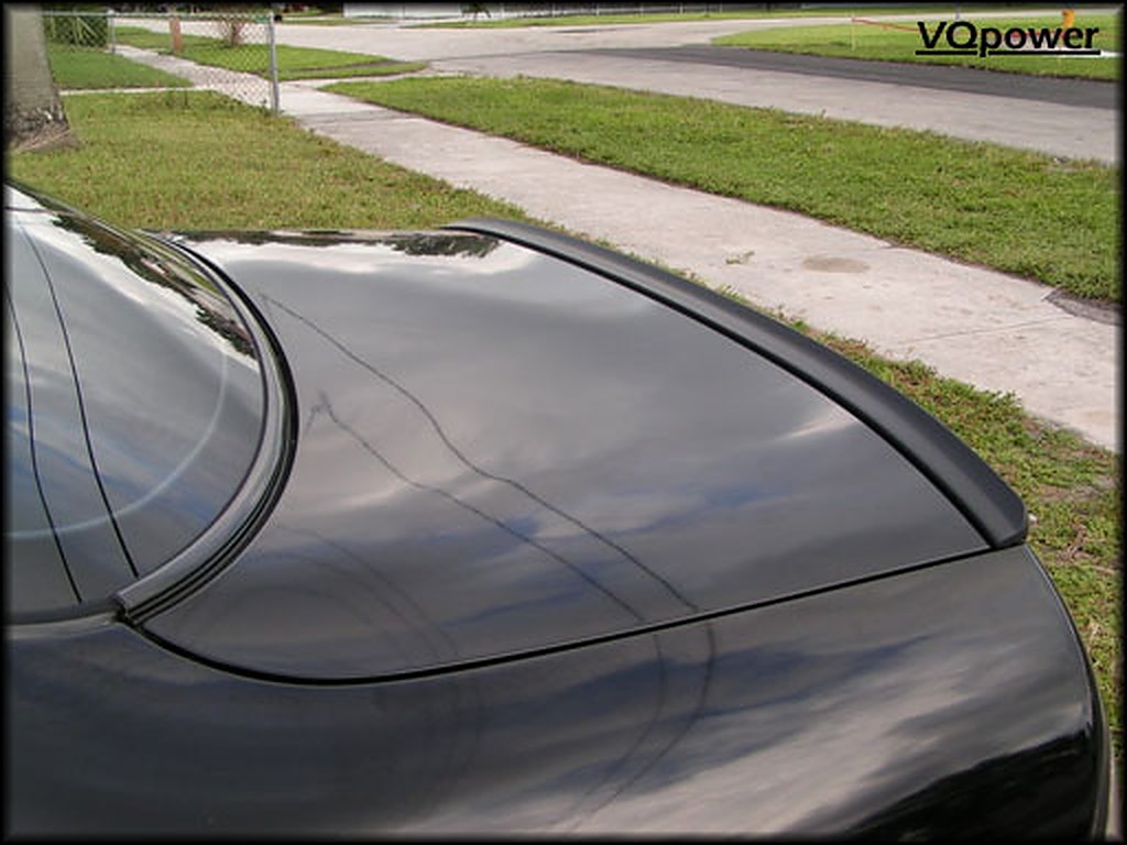
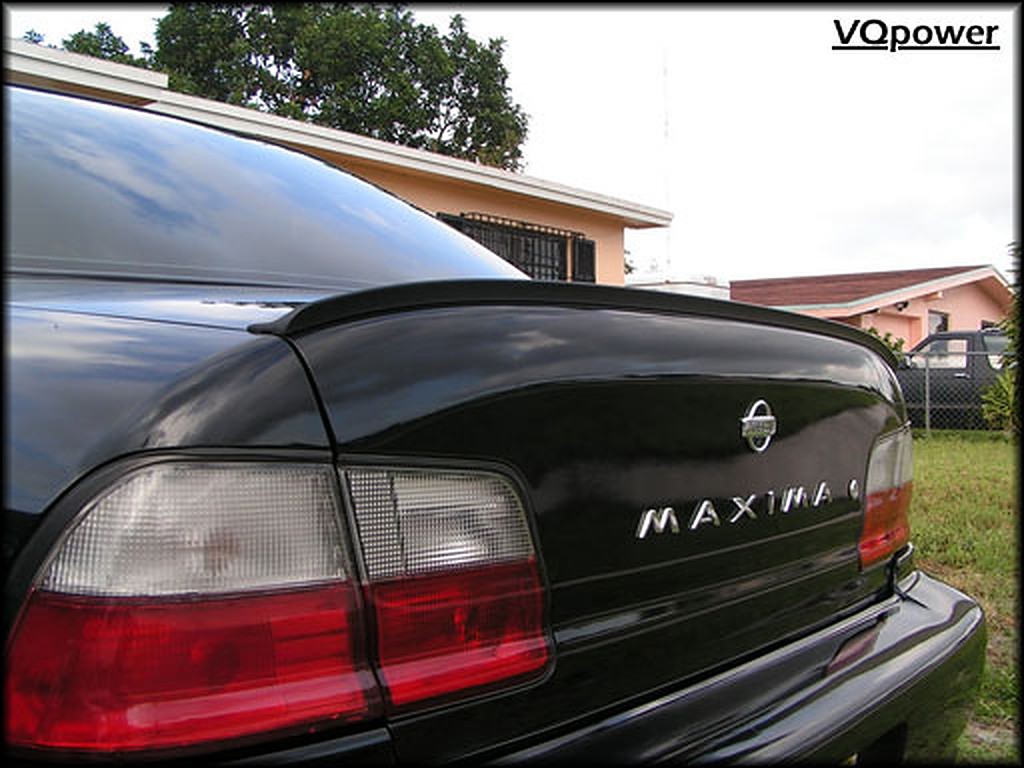
I was able to get a hold of an A32 lip spoiler which is really designed for the 1st gen I30. I was going to give it a try and put it on my A32 Maxima(1995-1999). To my surprised when it came to my door, it was way more flexible than I imagined it to be. That making it a plus because install would be more easier to perform. I put it flush with the very edge of the trunk, and aligned each corner to extend a little past the edge(slightly longer on each side). Masked off the line on the trunk for later placement, rubbed some alcohol along the area and put the lip down. Looks amazing, and I encourage those spoiler-less Maxima owners to pick one up.
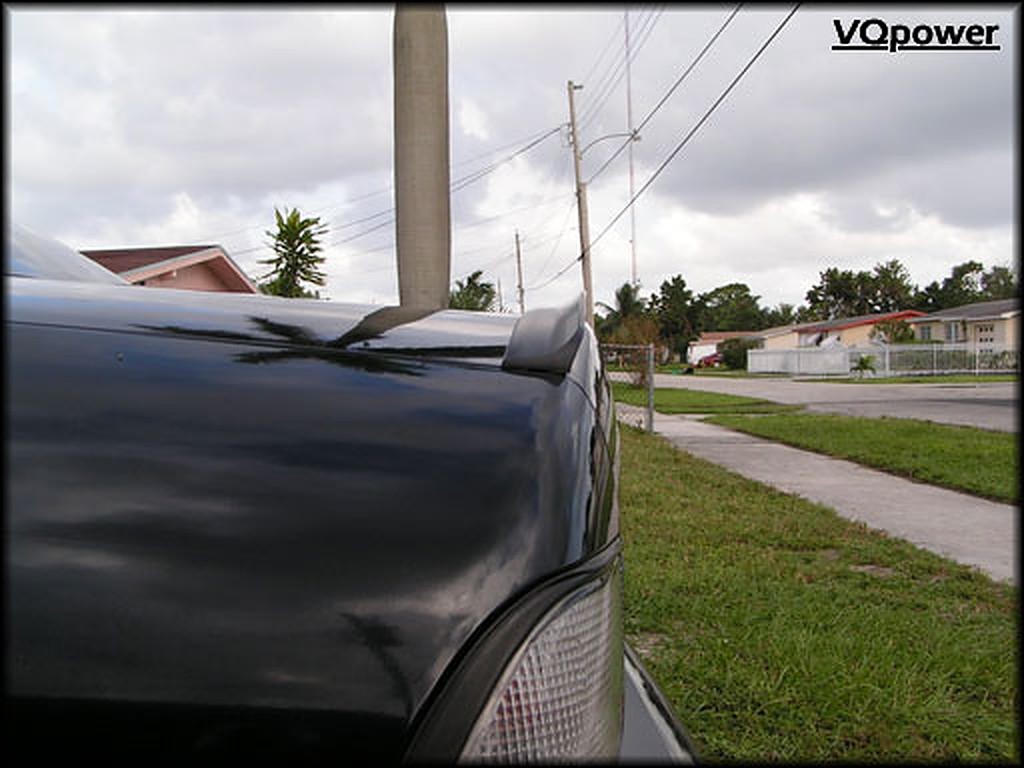
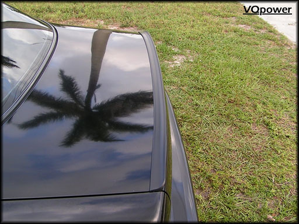
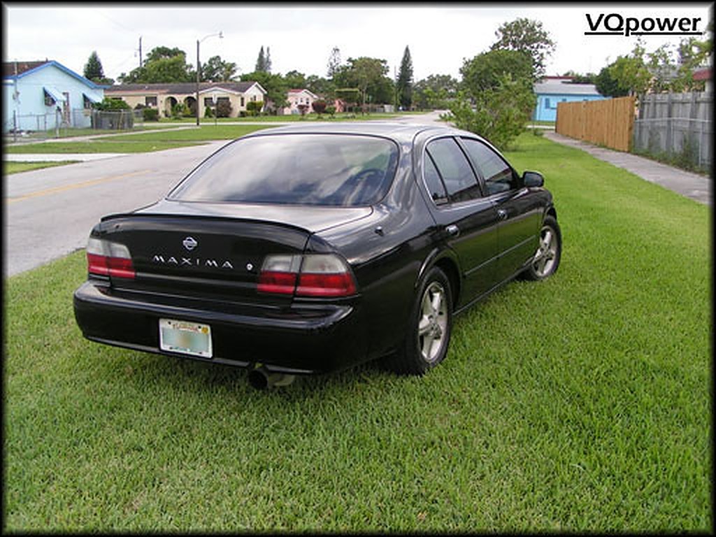
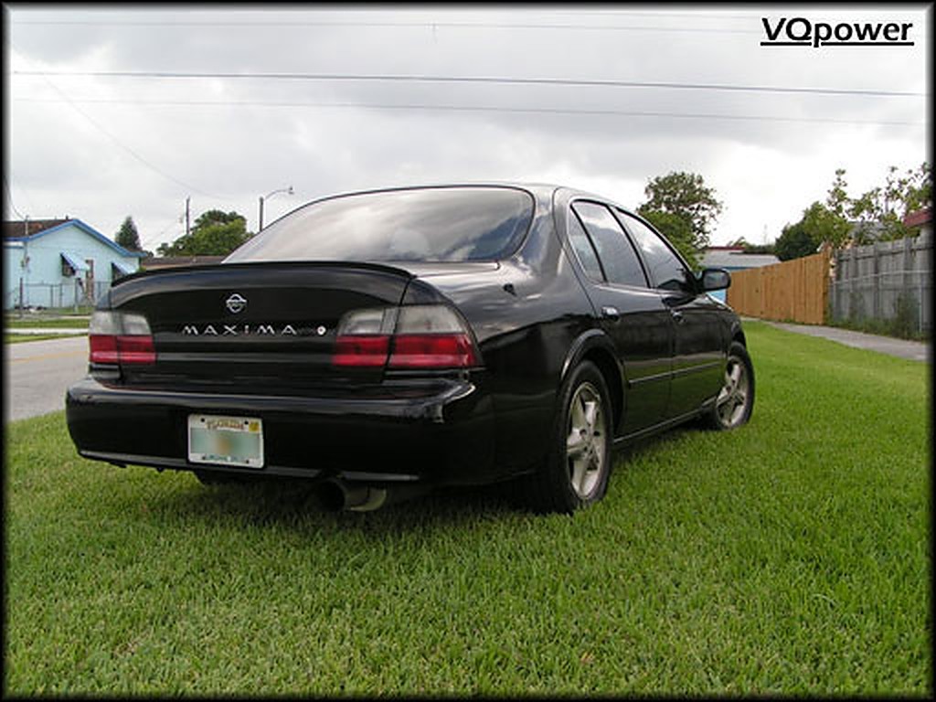
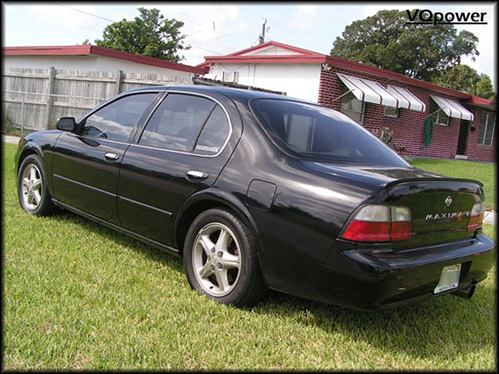
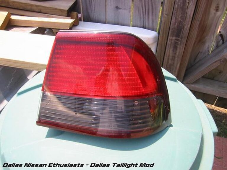
Community Member Credit: Dallas Nissan Enthusiasts
This write-up below is a step-by-step set of instructions with pictures on how to do the Dallas Taillight Mod. It is similar to the 97-99 Red/Clear mod but with a twist.
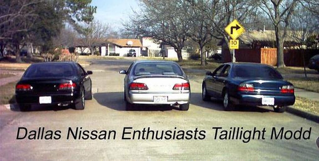
Things you will need:
This is the paint we used.

We will start with the reverse light assemblies.
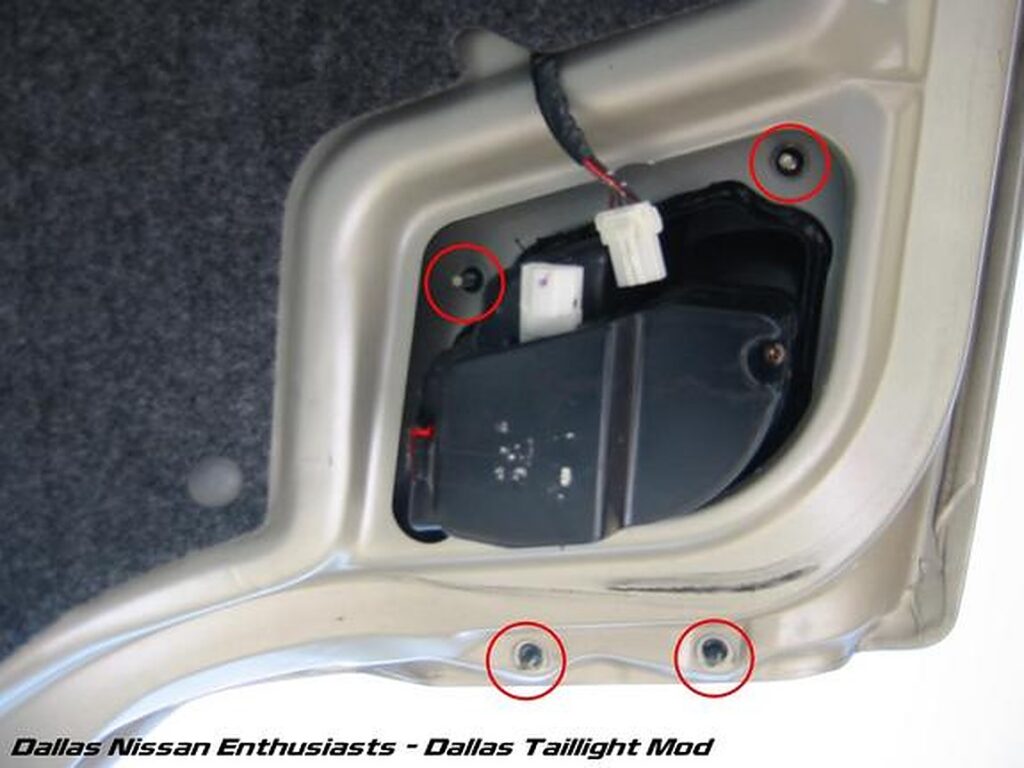
First, unscrew the 4 8mm nuts that hold the reverse light assembly onto the trunk lid. All 4 are highlighted by the red circles. Once these nuts are removed, remove the screw that holds the plastic cover on the back. You should now be able to pull the small plastic cover off which hides the bulbs and sockets. Go ahead and unplug the wiring harness located at the top of the pic.
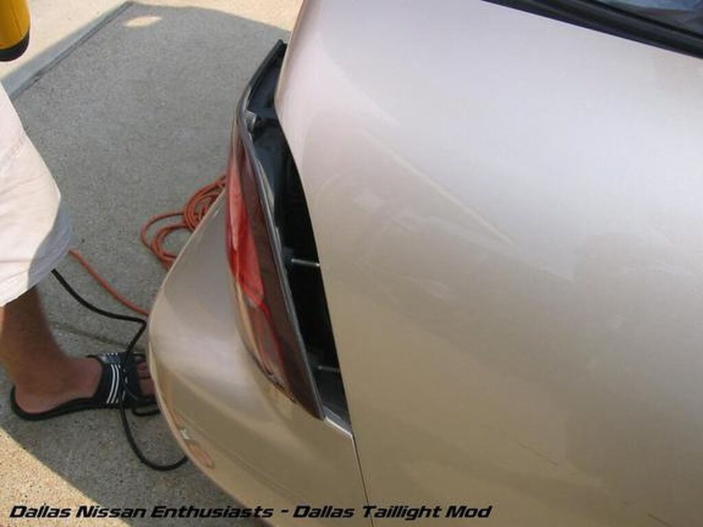
You can now take the flat head screw driver and stick it in between the taillight assembly and trunk lid (as shown on the left) and pry it up (as shown on the right). As it comes up, you can use the heat gun to heat that black goo up which will make it easier to pull it off and make the assembly cleaner once it is off.
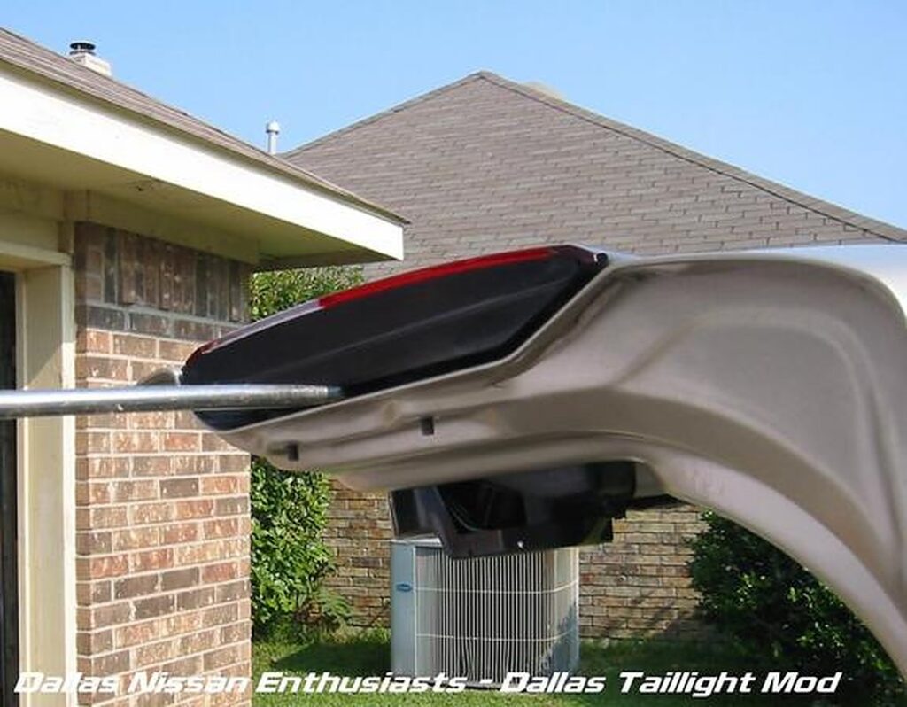
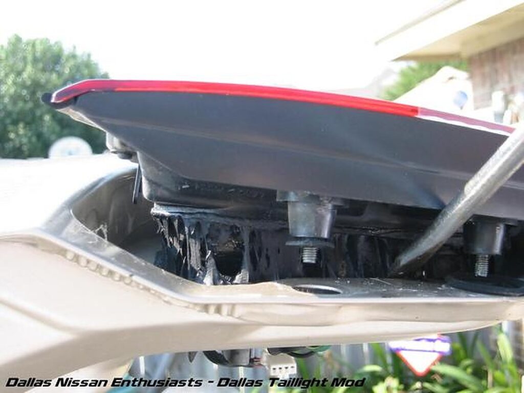
Once you have pried that end up, you can use your hands and lift the assembly straight out of the trunk lid.
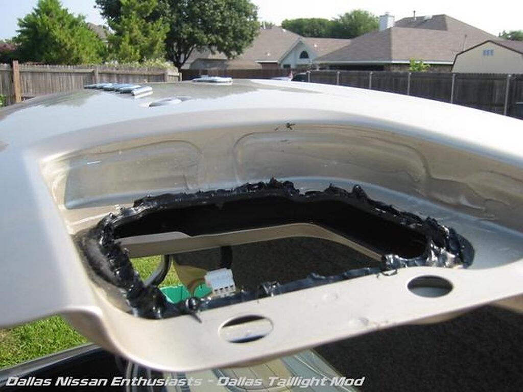
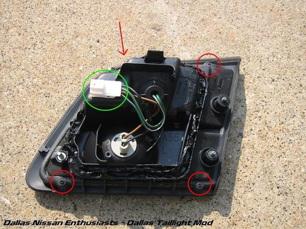
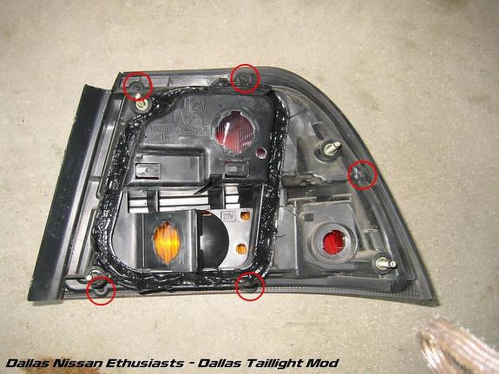
Now that the reverse tail assembly is out, you need to remove the lighting wiring plug from the assembly and remove the four screws. The plug is marked by the green circle and the four screws are marked by the red circles and the red arrow. Using the flat head you can pop the plug off by pushing on the plug from the ride side with a fair amount of force.
Now we can begin on the turn signal assemblies. Again, unscrew the four nuts which are marked by the red cirlces and the red arrow (didn’t get picture of all four). You will have to pull those white plastic things off the two inner bolts to remove those nuts. A set of needle nose pliers can help if you can’t pull them off with your hands. You can now use the screw driver again and pry from the trunk side, use the heat gun again if you want (makes things easier and cleaner), and pull the assembly straight out (as shown on the right).

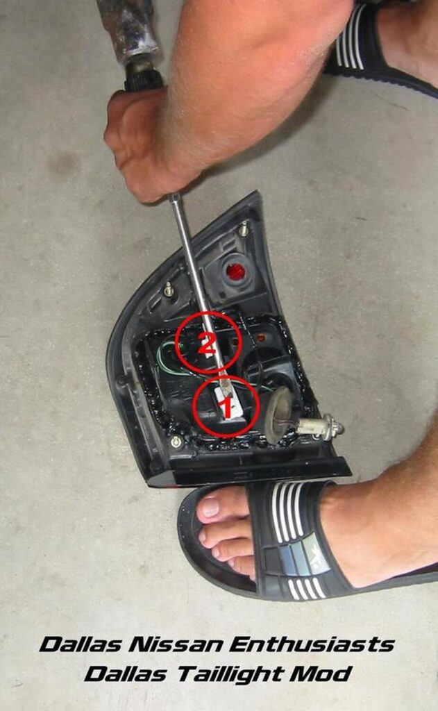
For the side, there are two light harness plugs to be popped off (left) and 5 screws that you must remove (right). You can see I am using a big flat head screw driver and a very small sledge hammer to remove the plugs. This is overkill, but it was close, available, and it worked.
Your ride should kinda look like this now. Pretty huh?
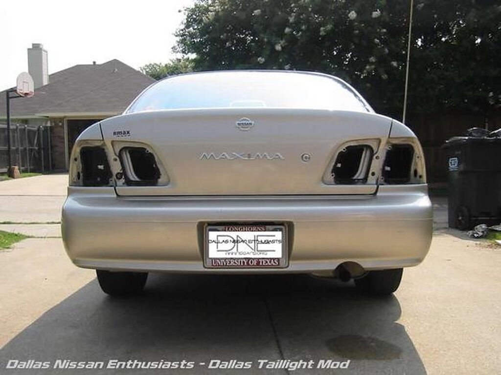
Now with all the tails removed, all the screws removed from each assembly, and all the lighting wiring remove, we can go inside and begin the hard part.
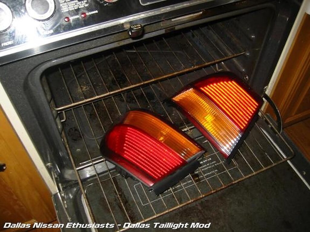
From this point, some people have chosen to sit with a heat gun and heat the edges of the assemblies but that seems to difficult to me, so I use the oven. Set your oven to 200 F degrees. Once the oven has heated up for a bit, place the reverse tail assemblies or the signal tail assemblies in the oven. We did the reverse first, but it doesn’t matter. The pic shows the signal tail assemblies on the lowest oven rack to really get them warm.
The tails should be in the oven for 10 mins (a little longer won’t hurt). Once 10 mins has passed, pull your tails out (WARNING: They will be VERY hot). Use something with a long flat tip (I ended up using that large untensil in my right hand in the pic on the right) to pry the lense from the plastic assembly (left). Be very careful not to crack your lense. You will have to pry fairly hard, but don’t over do it. Be patient. If possible (a friend is helpful here) use the heat gun at the same time to keep the glue hot and keep things cleaner as you pull the two apart (right).
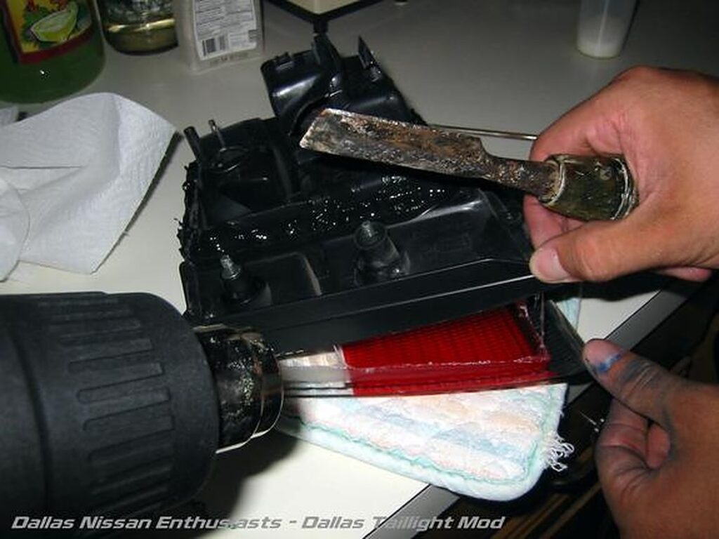
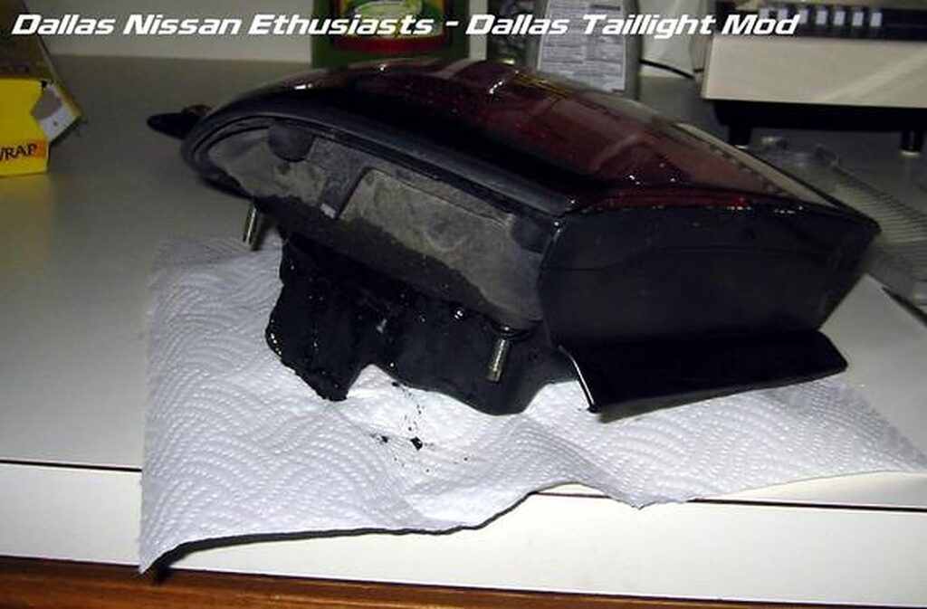
Opening the turn signal assemblies are a bit more difficult. Start by pulling the lense off from the straight edge. Once the lense is most of the way pulled apart from the housing, pull it straight out. The bottom left corner is a little weird in its design. Be careful with this part as to not break your lense. Now you must pull the orange piece of plastic out of the turn signal assemblies and the clear piece out of the reverse. You should be able to just pull. You will not need these again. Do not pull the clear pieces from the upper half of the tails where the brake lights are. This makes the light spectrum more spread out.
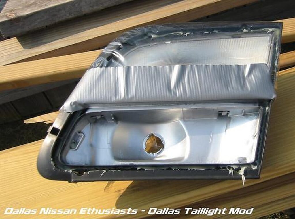
Now that all your lenses have been removed from their housings, prepare the housings to be painted. The best thing would be to use painting tape and some paper to cover the areas you do not want painted, but all we had at the time was duct tape and saran wrap. You can pick up painting tape at your local Home Depot or Lowes.
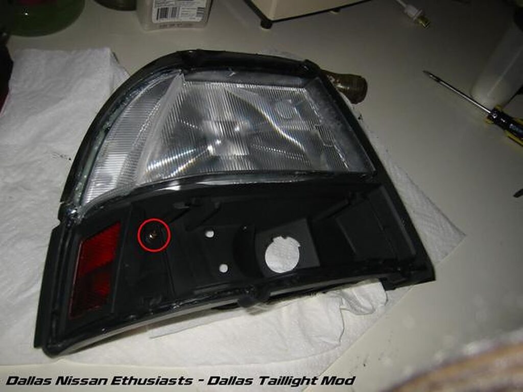
Now, for the turn signal assemblies, you must remove the little red side light cover by removing the one screw that holds it in (sorry no pic). Using the painting tape (or duct tape in our case) cover the reflective part. As to not paint it black. Some people have chosen to leave these covers out completely, but that is your choice.
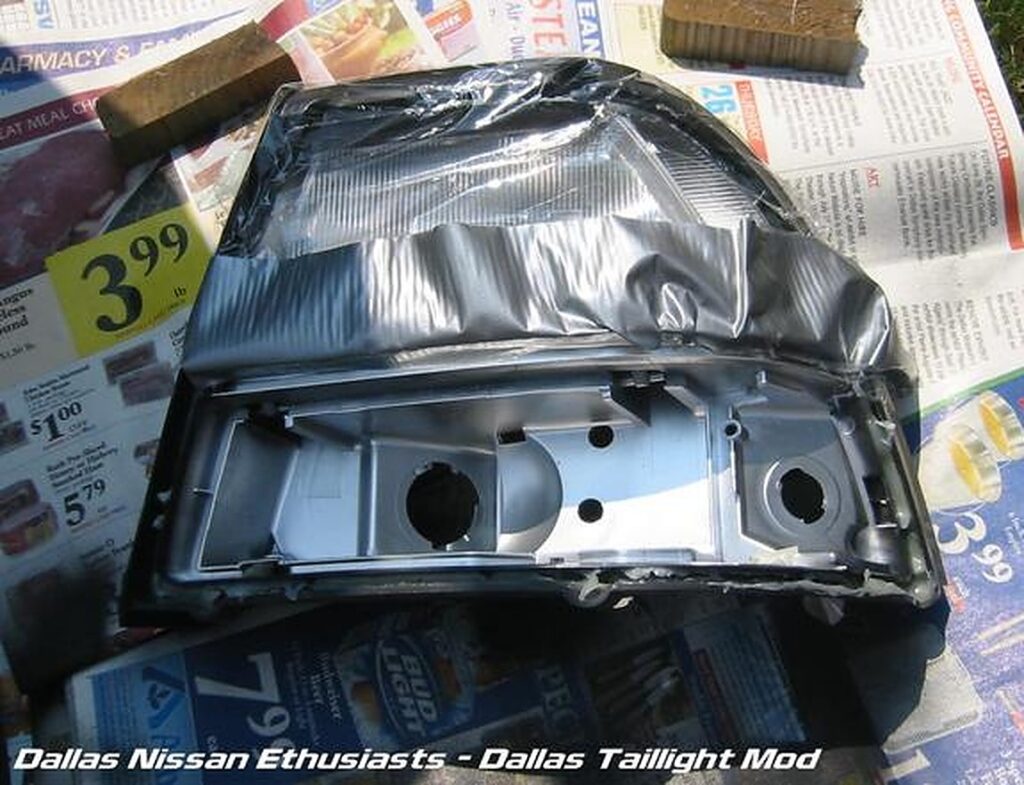
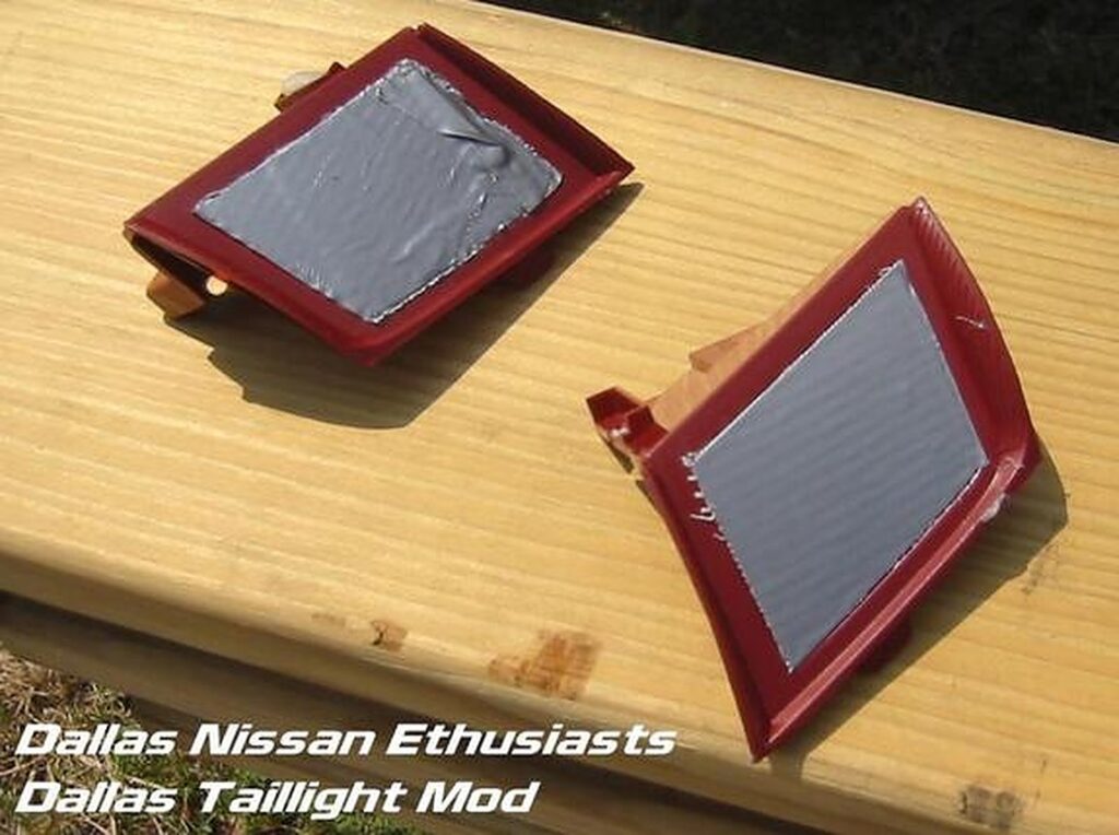
Once you have the protective stuff all put on the tails, you can spray paint your tails. Be sure to get all the corners and hard to get areas for that clean look. I recommend holding the can 12 to 18 inches away from the housing itself as to not get overspray. We put two coats of paint to make sure we got everything. This is what your tails should look like.
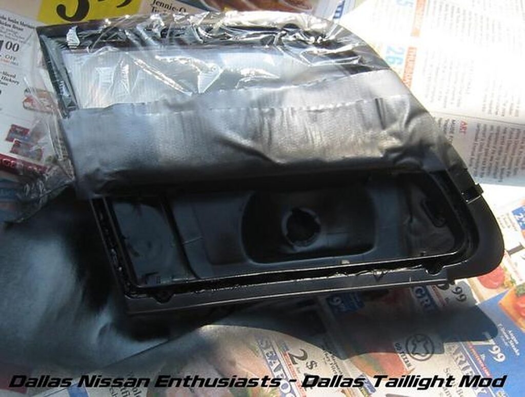
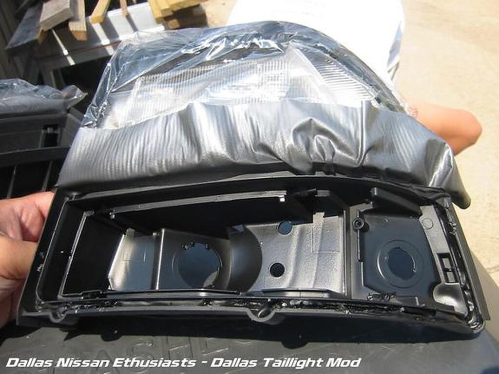
Now take your paint turn signal tail assemblies and your painted reflectors and put them back in. Don’t forget to put the screw back in (red circle).
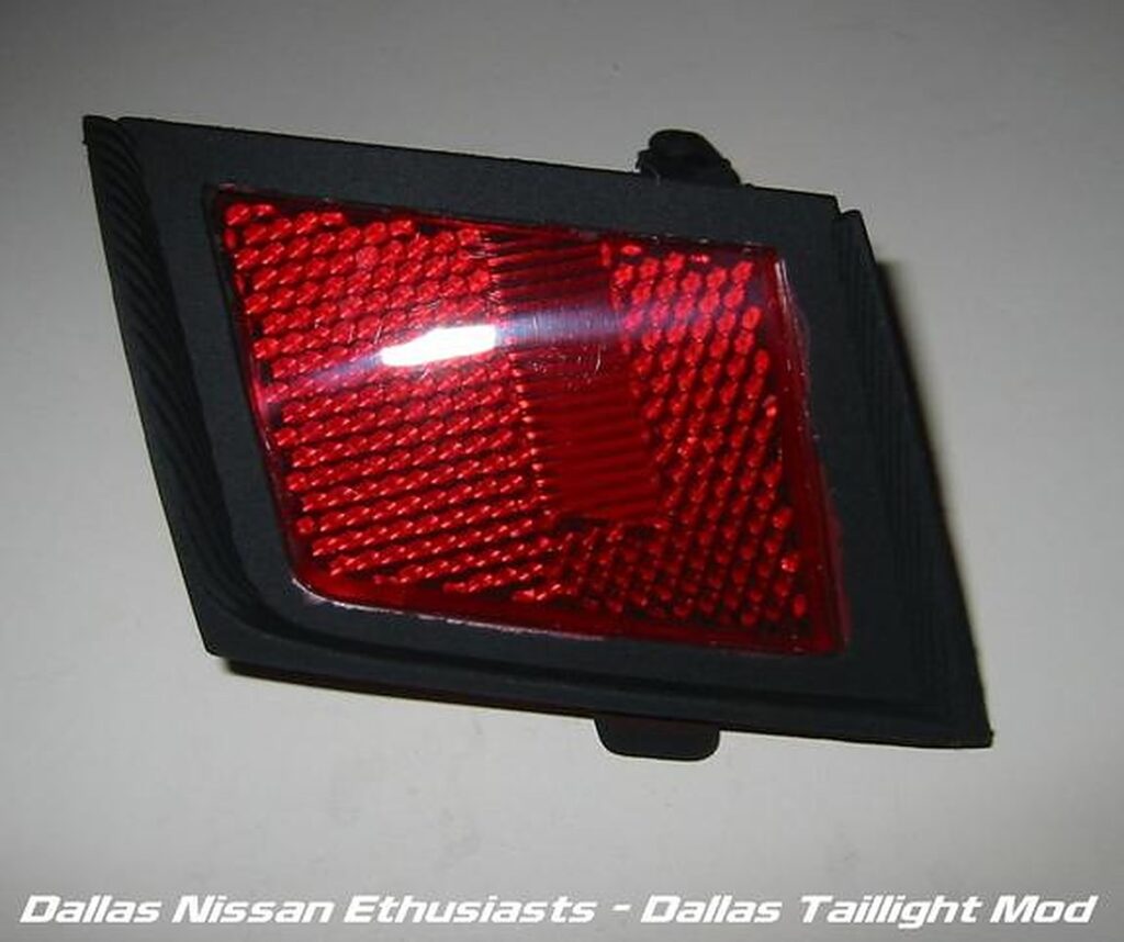
Once the paint has dried, you can put the lenses back on the housings. Use the heat gun to heat up the glue a bit first. Once they are back together, put them in the oven for about 5 mins at 200 degrees. After 5 mins pull them out. The glue has been reheated so that you can push the lenses onto the housing more for a better seal. Once all together, your tails should look like this.
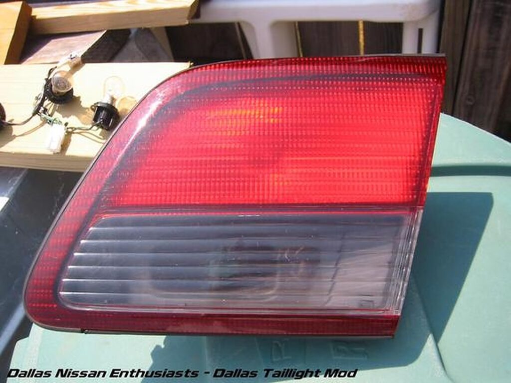
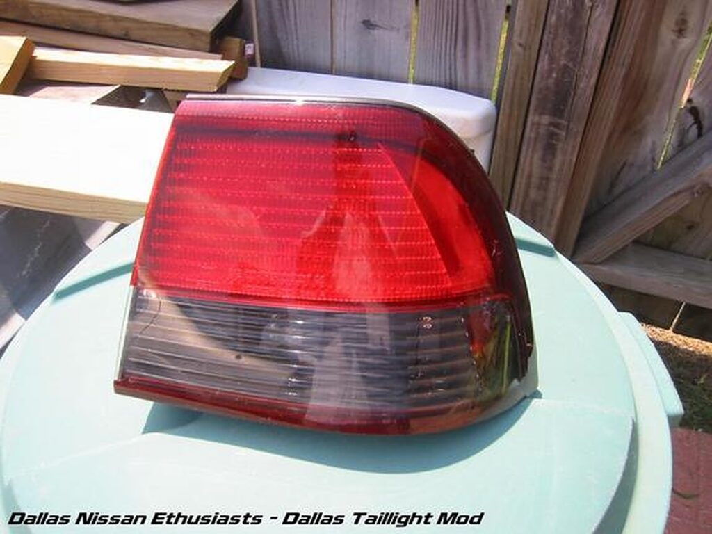
Now all you have to do is put the tails back in and you’re done! What a nice a$$ you have. 🙂
Tools:
Info:
This modification is a very easy process that allows the fog lights to be on with the parking lights. It also allows the fog lights to remain on with the high beams. This process was done on my 1997 Nissan Maxima SE, automatic.
Let’s Begin:
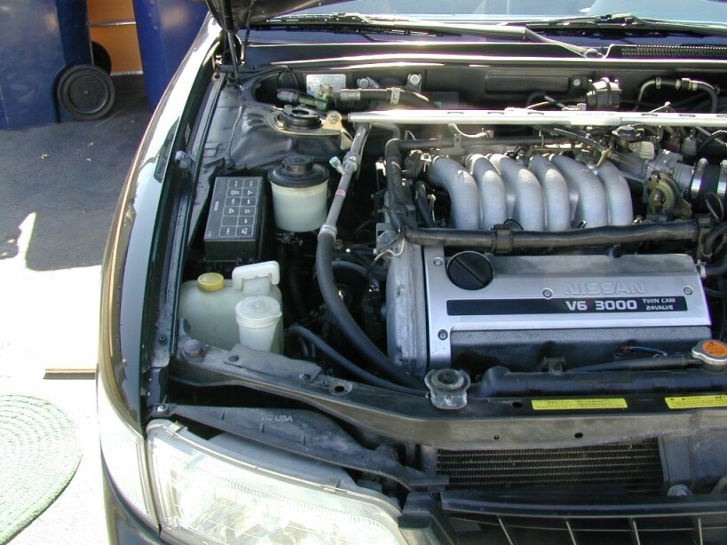
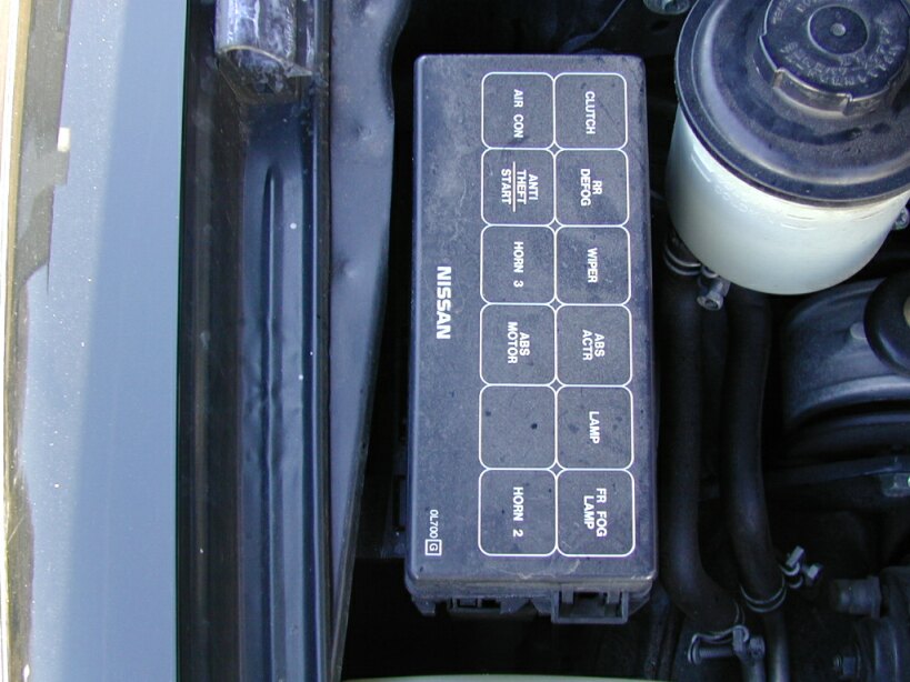
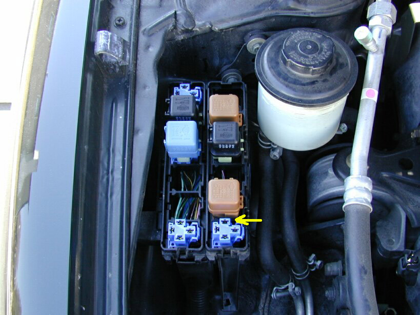
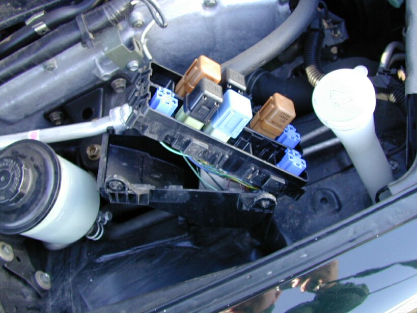
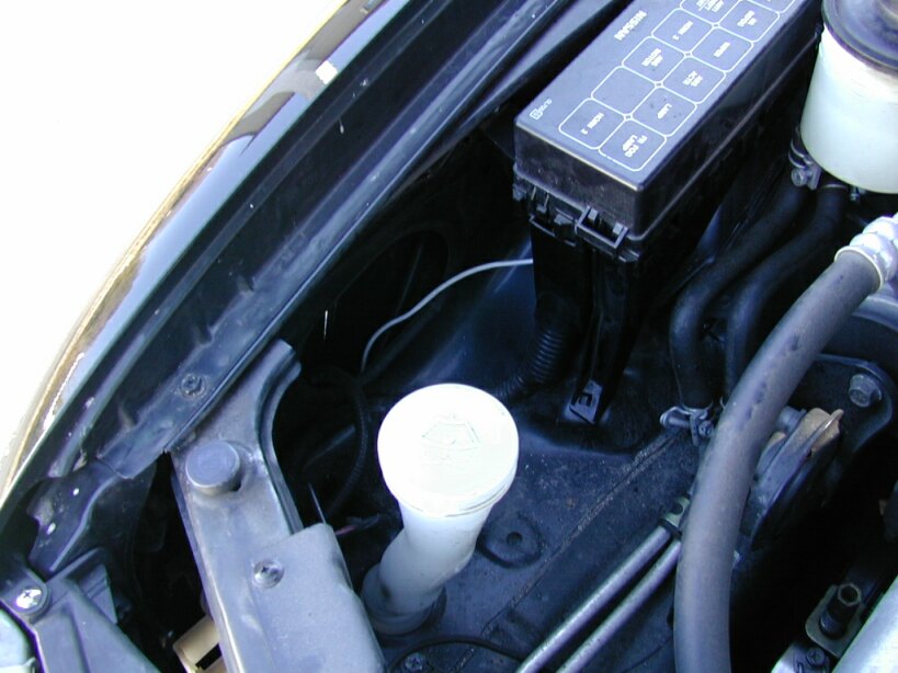
The relay box is located on the passenger side of the engine bay, right next to the coolant reservoir. Close up of the relay box. Notice the Fog Light relay is marked.
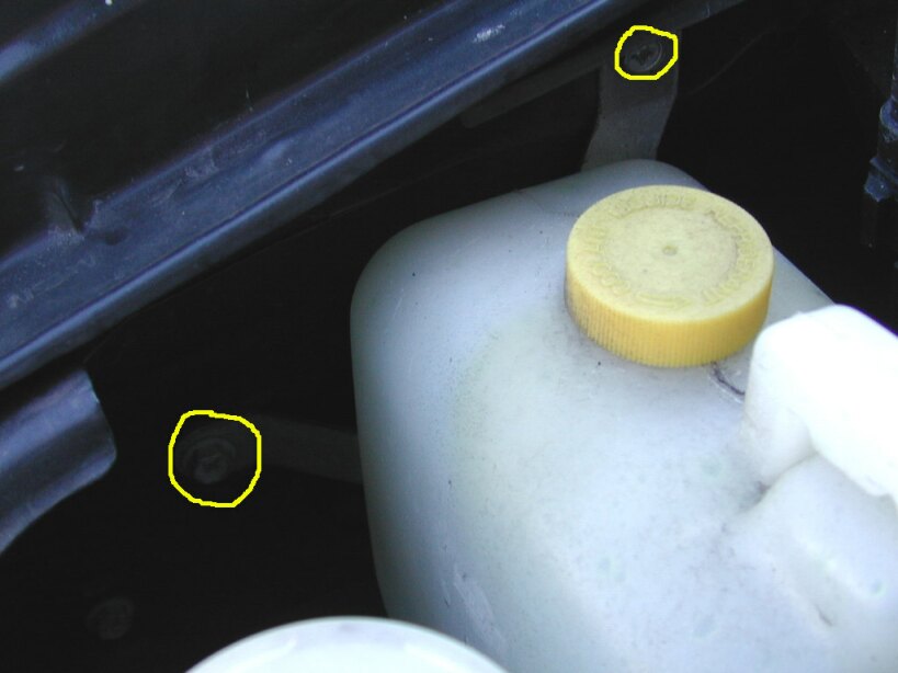
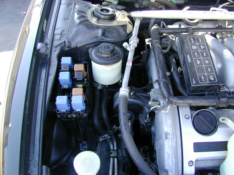
In front of the relay box is the coolant reservoir. Remove the coolant reservoir by removing the two hex head screws. You can use a large Philips head screwdriver or a 10mm socket. Place the reservoir out of the way. I put it in between the engine and the radiator, it’s sits there without disconnection the hose. Remove the top of the relay box. This is easy, there are only a few clips to undo. Put the top on the side. > 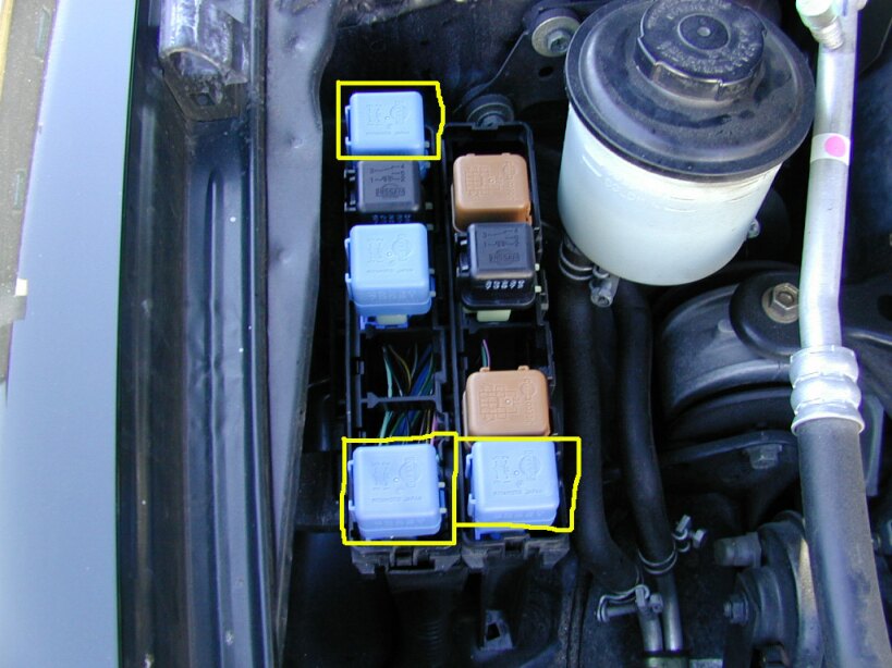
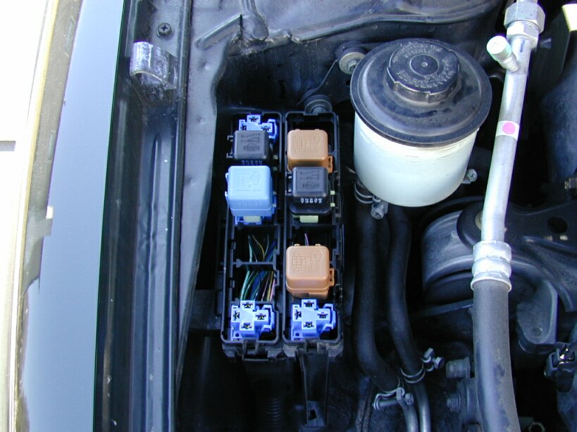
Now you can see the relays.
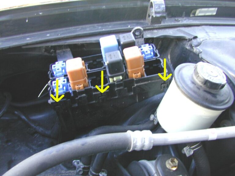
The three relays highlighted in yellow need to be remove in order to remove the relay box. I believe if you have a manual transmission that there is a forth relay that needs to be removed (it would be in the upper right of the relay box)
**These relays should all be the same, but just in case make sure you remember where they originally were.**
This is what the box looks like with the relays removed.
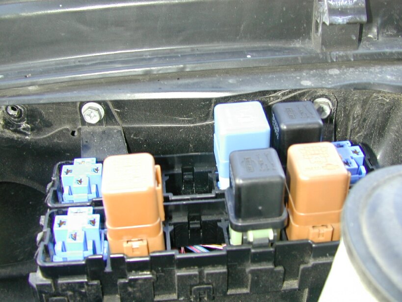
Turn the lights on and test the relay with the voltmeter (or other electrical device). The marked terminal should give around a +12V reading. You can use the terminal across from it as the ground. The two hex head screws need to be removed. You can use a large Philips head screwdriver or a 10mm socket.
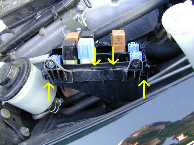
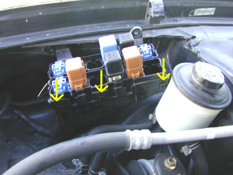
^^FENDER WALL SIDE^^ ^^ENGINE SIDE^^
Once the relay box is remove from the frame, it need to be taken apart. There is an upper and lower piece. In order to take it apart there are three clips on the side that faces the engine and two of the same clips on the fender wall side. But on the fender wall side there are also two additional clips. I used a small screwdriver to unlatch all the clips, be careful not to break anything. All the clips are marked in the two pictures above.
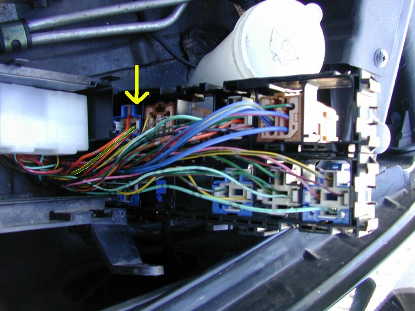
Here is a picture of the two pieces of the relay box apart. With the relay box open, you want to locate the +12V terminal of the Fog light relay. It’s the green/yellow wire. I’ve marked it with an arrow and outlined it in yellow. You want to cut this wire, make sure to leave yourself enough wire on the relay side of the wire to splice into. Once the wire is cut, tape off the +12V wire with electrical tape (this is the half of the wire that isn’t attached to the relay)
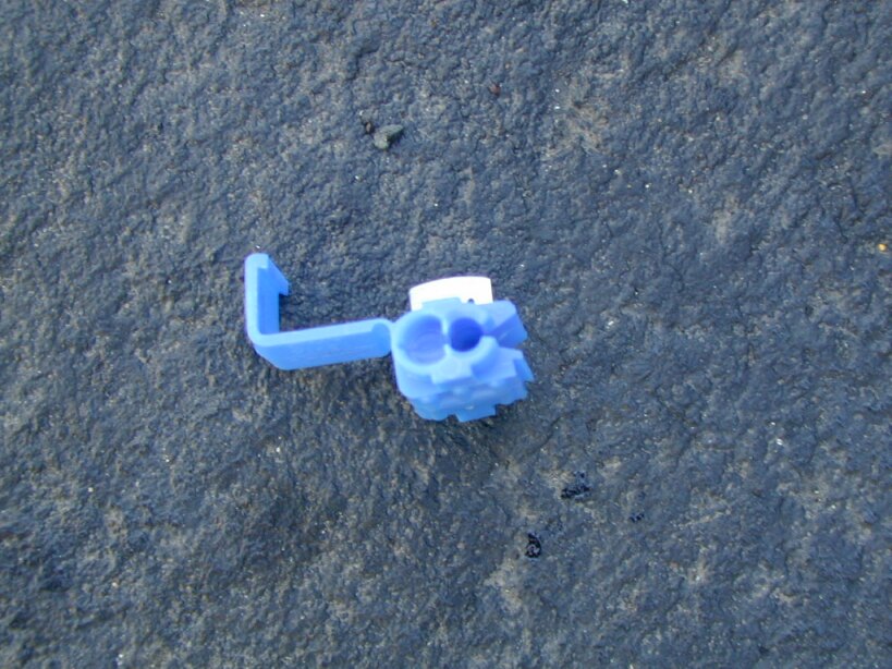
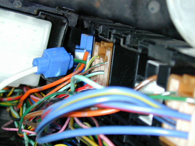
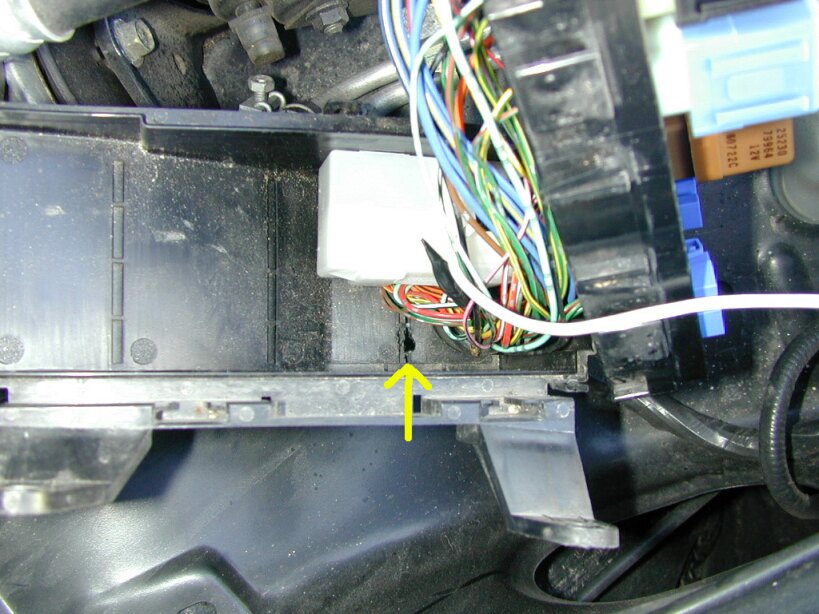
^^WIRE TAP^^ (Radio Shack). Splice into the green/yellow wire with a long wire, around three feet. I used a wire tap to do this, but it can be done in other ways. Make sure to wrap it with enough electrical tape. The new long wire needs to be run out of the relay box. So I cut a small hole in the bottom to run the wire out of. You can also see in the picture the original +12V wire that is cut and wrapped in black electrical tape.
Put the relay box back together.
Reattach the box to the car with the two hex head screws.
**To test the lights: Turn on the parking lights, then touch the new wire to the positive terminal (RED) of the battery. The fog lights should turn on when the wire touches the battery. They should also remain on with the high beams.***
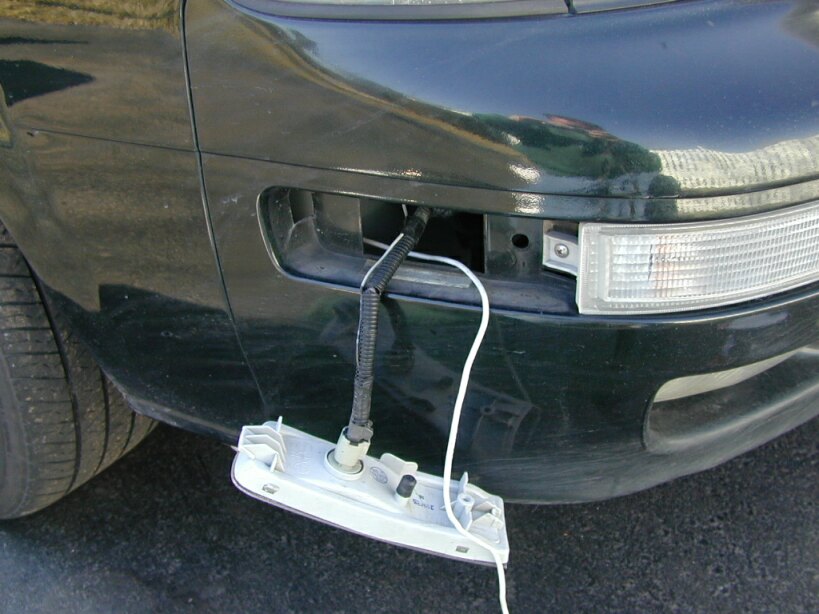
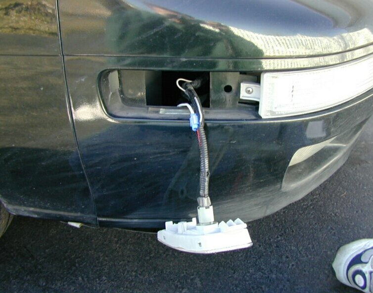
Remove the corner light with a screwdriver (wrap with a cloth to protect the lenses), it should pop right out. Run the wire through the fender wall to the corner light. Splice the new relay wire into the red/blue wire. Again, I used a wire tap and then wrapped the entire thing with lots of electrical tape. Push the lenses back into the bumper.
YOUR DONE!!!
Turn the parking lights on and make sure the fog light switch is on too. Now your fogs will also be on. Turn on your headlights with your high beams on, your fog lights will remain on.
Member Credit: macdonjh
I’ll start with the reconnaissance I did in the front door. Several photos below:
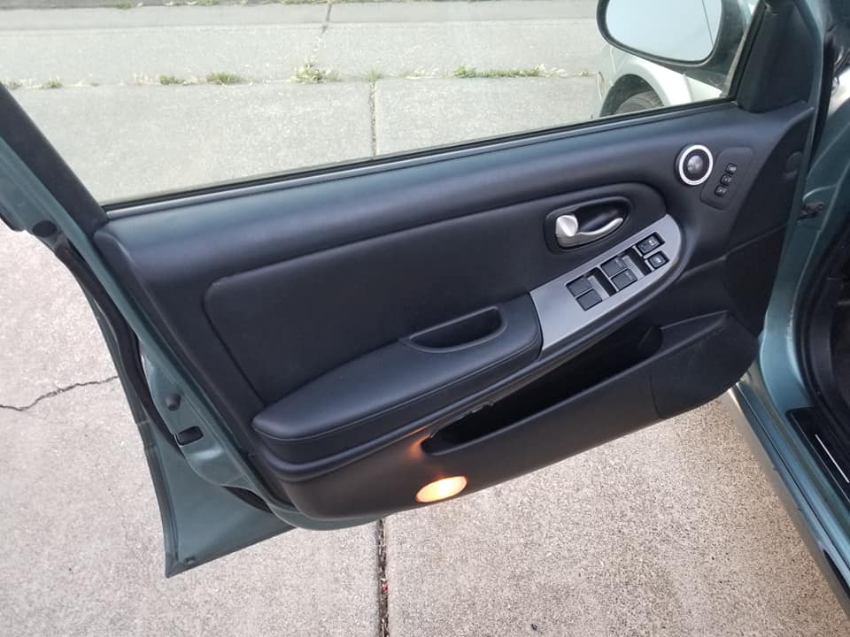
Front door: this is just a photo of the front door with the finisher removed.

Front door speaker: a close-up shot of the 6″x9″ factory speaker in the front door. It has a plastic cone, foam surround and a paper whizzer cone. Another user asked for dimensions in a different thread, I’ll post those here: measuring from the back of the mounting flange the mounting height (how tall the speaker is measured from whatever you’ll bolt it to) is 3/8″, mounting depth is 3-1/8″, magnet diameter is 3-1/8″.
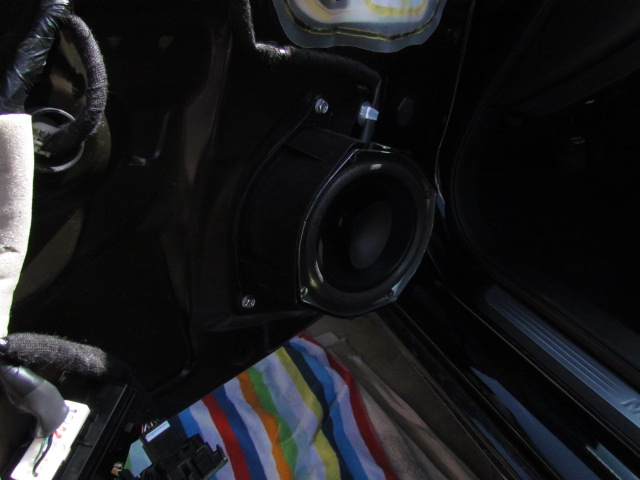
Front door speaker removed: gives you a look at the factory “enclosure” or “stand-off”. As Tommie70 said in his thread, there is a veritable cavern behind these door speakers. My installation will be like Tommie70’s in that I’m going to install plywood adapters into the factory “enclosures” and mount component mid-bass drivers there. Mounting depth with the “enclosure” installed is 7″. However, see below if you want to go a different route.
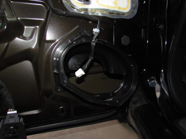
Front door speaker stand-off removed: Here’s what the door looks like without the factory “enclosure” or “stand-off”. The hole in the door is big enough (nominally 5-1/2″ x 8-3/8″) for you to reach at least half-way across the door for Dynamat installation. If you cut a plywood adapter to fit across this hole and match the factory bolt pattern (use the “enclosure” as a template) you could mount any coaxial speaker here you want. There is a structural bar across the door panel directly behind the speaker mount, but even with the bar mounting depth available is 4-3/4″. So without the “enclosure” you gain 2-1/4″ clearance between the speaker and door finisher for coaxial tweeters and such.

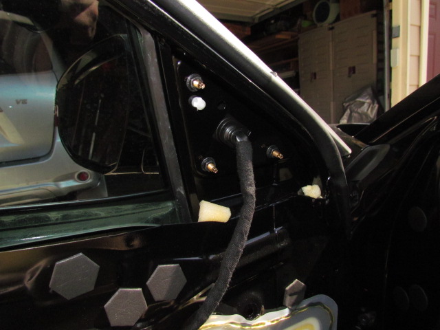
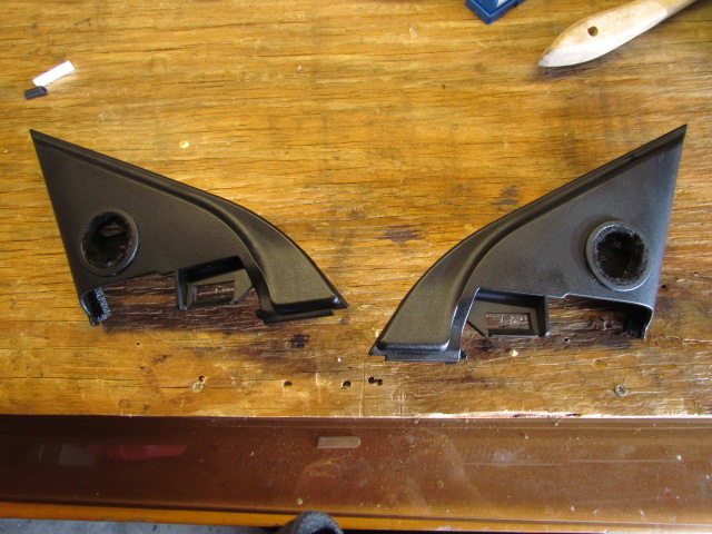
Mirror corner cover removed: this shows what’s behind that cover where Tommie70 mounted his front tweeters. None of the mirror mounting bolts or mirror control cable poses a problem, at least for the JL Audio 3/4″ tweeters I plan to install there.
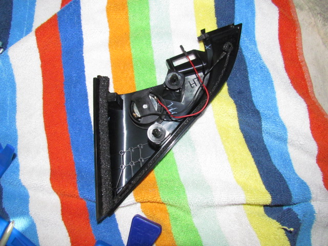
Mirror corner cover with tweet: this shows my 3/4″ tweeter resting inside the cover plate. I actually reinstalled the cover plate with the tweeter rolling around and didn’t have any trouble, so that’s where they’ll go after I’ve installed the new wires.
I forgot to run a fish through the factory boot between the frame and the door, but just feeling around it seems like there’s room enough to run a 16ga wire through the boot and avoid drilling new holes in the frame and door. I think I’d prefer to mount my cross-overs in the door anyway for shorter wire runs from the cross-over to the drivers. If I can’t fish a new wire through the factory boot I’ll consider pulling the factory speaker wires back through the boot to make room.
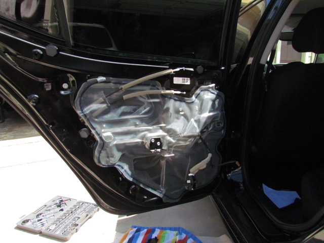
Here’s what I found when I took the rear door apart.
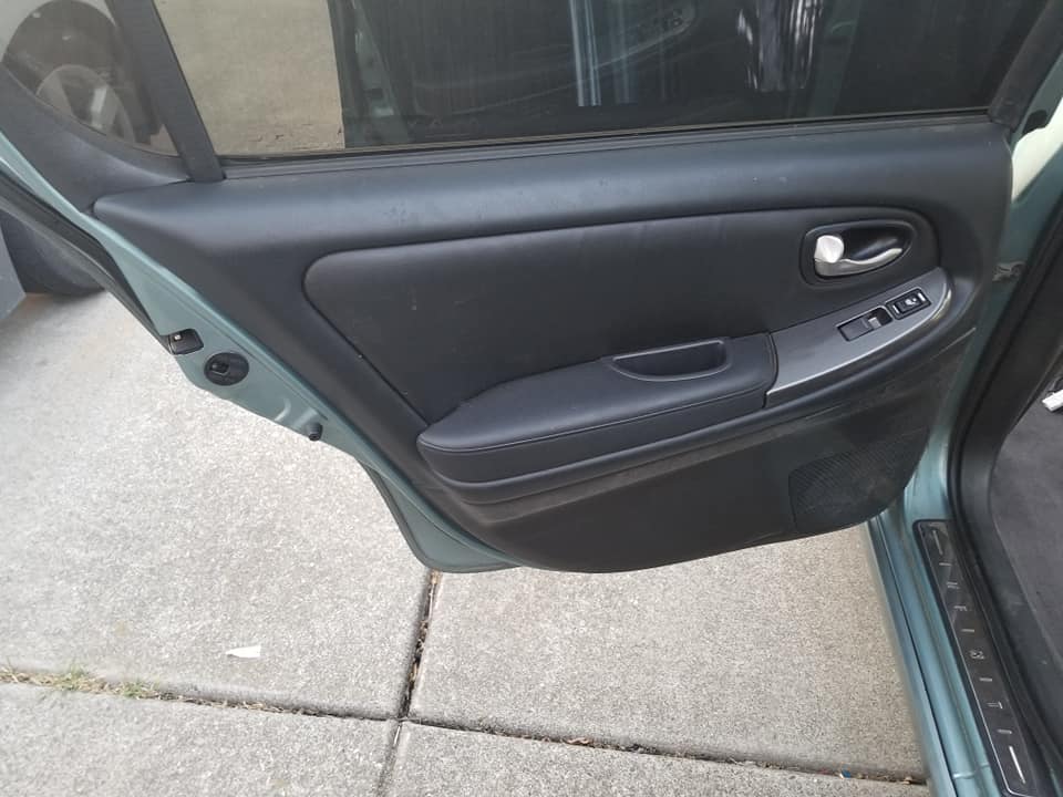
Rear door: A view of the rear door without the finisher installed.
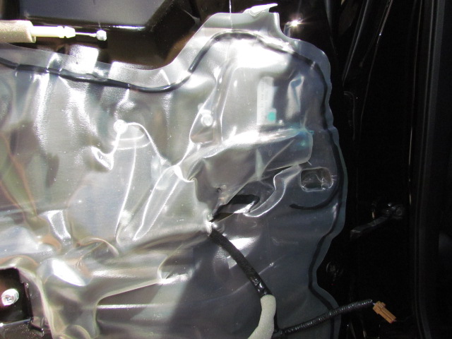
Rear door speaker location: a close-up photo of the inside of the rear door where the speaker would be. The speaker “sits” to the right of where that black cable (window switch) comes through the plastic. It’s hard to tell in this photo since I didn’t remove the plastic, but there is a metal panel directly behind the rear door speaker position, so after-market speaker options will be limited.
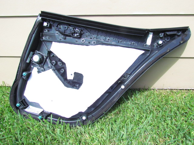
Rear door finisher: a photo of the inside of the rear door finisher. To fully remove the door finisher, remove the entire window switch assembly, not just the white part of the plug/connector. Then you can disconnect the speaker wire and the finisher will be free.
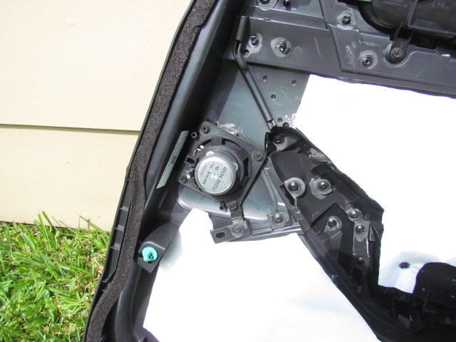
Rear door speaker: a close-up of the rear door speaker. The speaker itself measures 1/4″ from the back of the flange to the “face” of the speaker (mounting height), 1-3/8″ from the back of the flange to the back of the magnet (mounting depth) and the magnet is 2-3/8″ in diameter. I also measured the plastic mounting plate/ flange: 3-1/4″ square “outside-to-outside” with a square bolt pattern that measures either 2-5/8″ or 2-11/16″ on a side. Oh, yeah, the speaker itself is a paper cone, paper dust cap and foam surround.
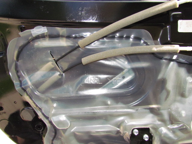
Rear door opener cable hole: if you’re really skilled, it might be possible to use this hole in the door for a different speaker mounting location. I think it would require major modification to the door finisher, though. Just thought I’d post a photo.
I’ve already stripped the screw holes that mount the rear door speaker, so please be careful. I am considering mounting rear tweeters in this location, rather than in the rear deck like Tommie70 did. If I do that, I’ll fill the screw holes with epoxy and then retap them when I mount the tweeters. I think tweeters flush-mounted to a 1/4″ plywood adapter plate would fit fine in this location.
I was not completely successful today: I got stymied trying to find a way through the fire wall. I couldn’t reach deep enough to get through either the hood release boot or the main harness boot. I didn’t feel comfortable drilling a new hole. I may pay an installer to finish this part of my install for me. Suggestions?
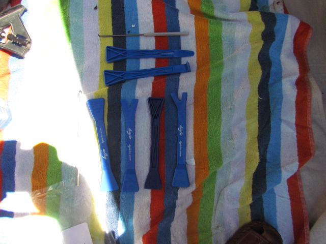
Here are the tools that I used for this part. Only a few needed.
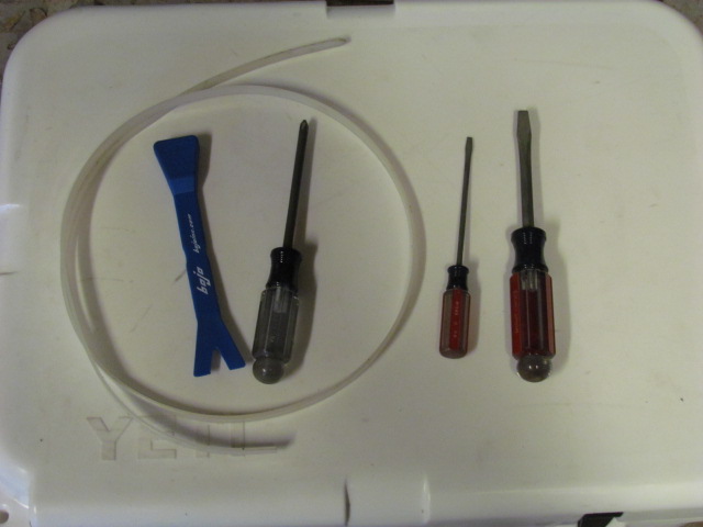
I’ll make several other posts with details of the bits and pieces I took apart to route the wires.
I started by taking out the rear seat, mostly. The seat cushion is as easy to remove as Tommie70 shows in his thread. The release handles are in the left and right corners and are easy to find by feeling under the cushion. Pull the release handle forward and pop the cushion up. Then pull it forward away from the seat belt clips. Be careful with the cushion: it’s only foam and upholstery, so it would be easy to damage/ crease.
The seat back proved too smart for me. For some reason only the passenger side seat back would fold down for me. I’ll have to talk with my dealer about that. I wasn’t able to remove the seat backs as you can see in the photos. The side bolters are held in place at the top by a couple of “pins”, just pull gently but firmly toward the front of the car and they will come loose.
Even with the seat back only partly out, I could follow the factory harness from the driver’s side sill into the trunk using the plastic wire fish I bought.
Sorry I don’t have more photos, most of them didn’t come out right.
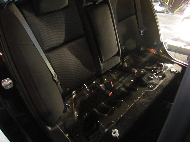
I didn’t do things in this order, but for these posts, I’ll go from back to front.
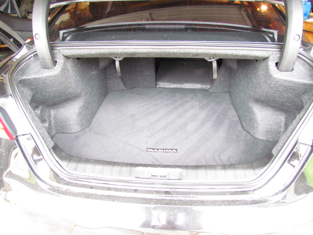
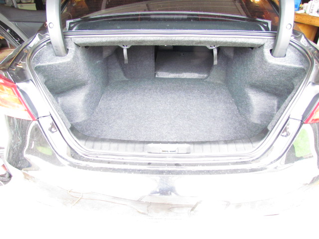
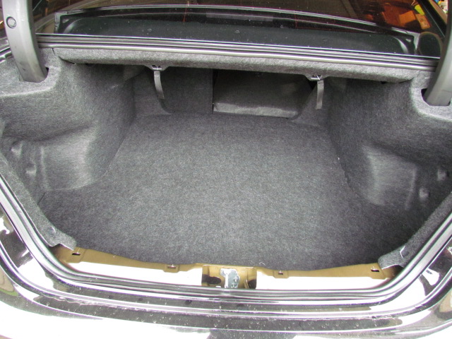
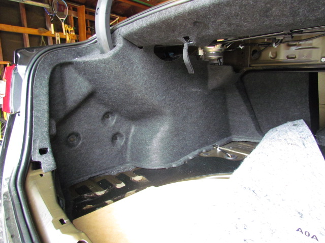
To get access to the trunk, start by taking out the cargo net and the trunk mat. Next, fold the carpet over so you can get access to the bottom edges of the left side finisher and the rear finisher.
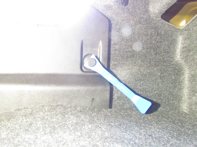
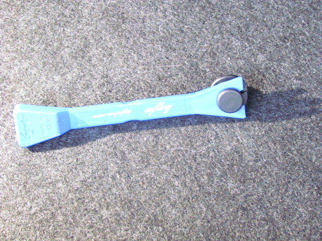
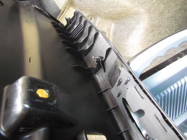
Next, remove the rear finisher. First, take out the knobs that hold the cargo net in place. These are “super size” dual clips, so use a trim tool to release the top “button” the pull the knob out. There’s also a normal size dual clip which you can release with a screw driver. The rear finisher is held in place with four or five snap clips, pull gently but firmly straight up and it will come out.
The left side finisher is held in place by four or five dual clips and a bit of Velcro. One of the dual clips is in the “roof” of the trunk, so you have to look a bit. This opens up most of the left side of the trunk for wire pulling.
Once the rear seat cushion is out, the sill finishers can be removed by pulling gently but firmly straight up. I also released the finisher for the B-pillar, but didn’t remove it all the way. That at least gave me the ability to reach under that finisher for pulling the cables.
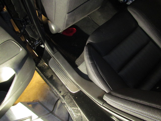
The kick panel finisher in the front of the car is a little harder to remove. It pulls straight away from the wall of the car, but the clips are tight. I didn’t post a photo of this, but I did pull the floor mat out and rolled the carpet out of the way looking for better access and visibility to the fire wall.
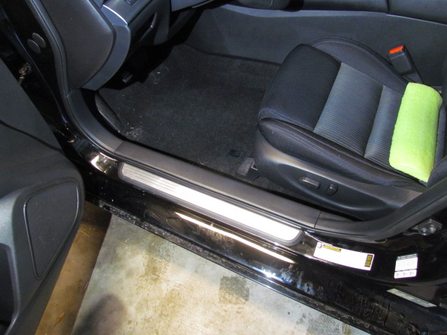
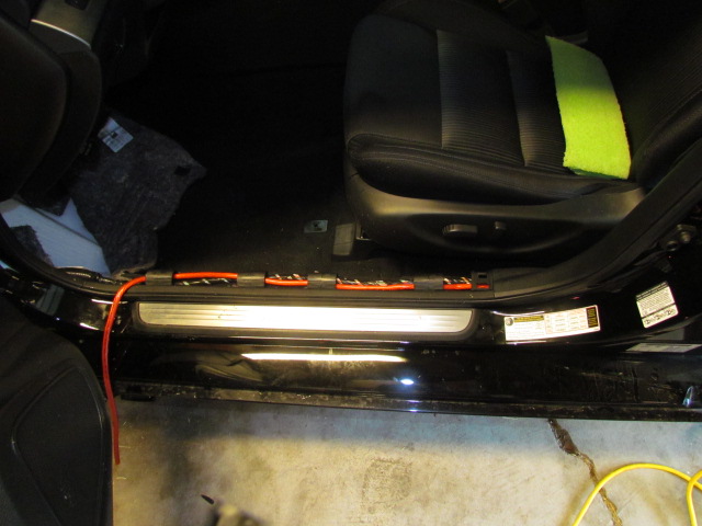
As you can see, there is plenty of room under the sill finishers for more wire. I am running 4 ga power and 16 ga speaker wire. At this time, the spare wire is coiled up and tucked up above the parking brake. I’m going to try to fish the speaker wire through the factory boot to the driver’s side door tomorrow. I may make another attempt to get through the fire wall, too.
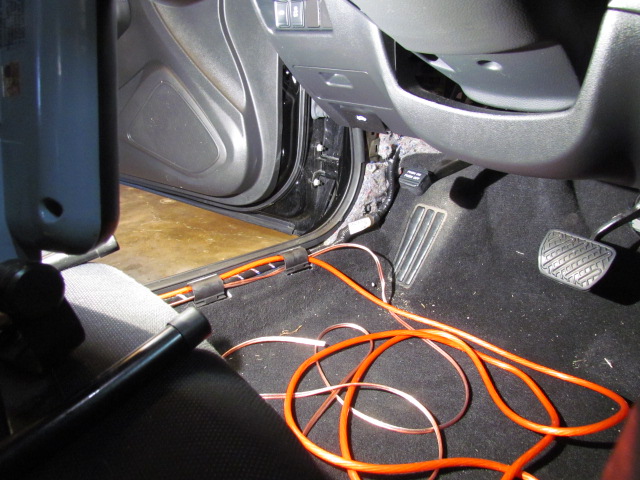
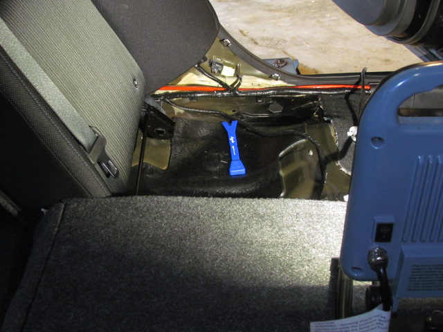
To try to get to the fire wall, I removed the tire and released about half of the wheel well liner. As I said, I didn’t have any luck finding a way through the fire wall today. Here are a few photos.
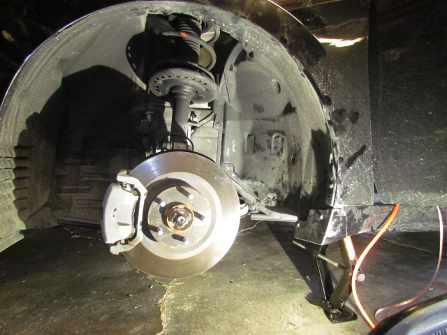
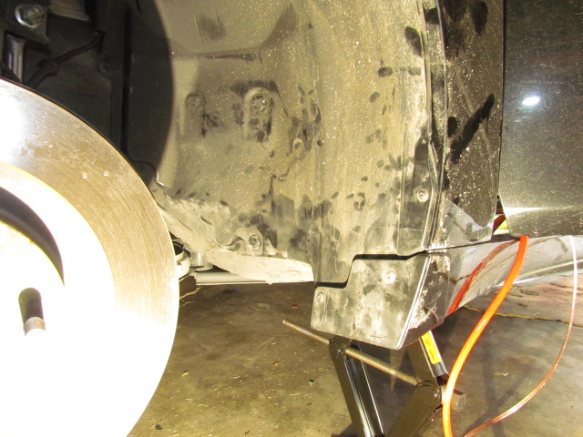
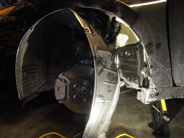
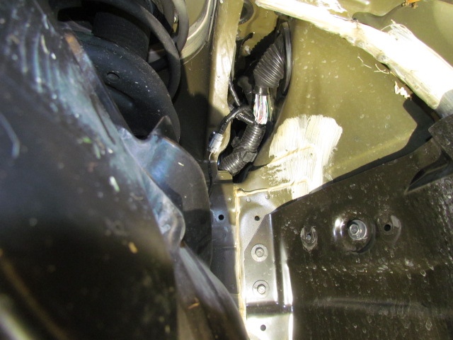
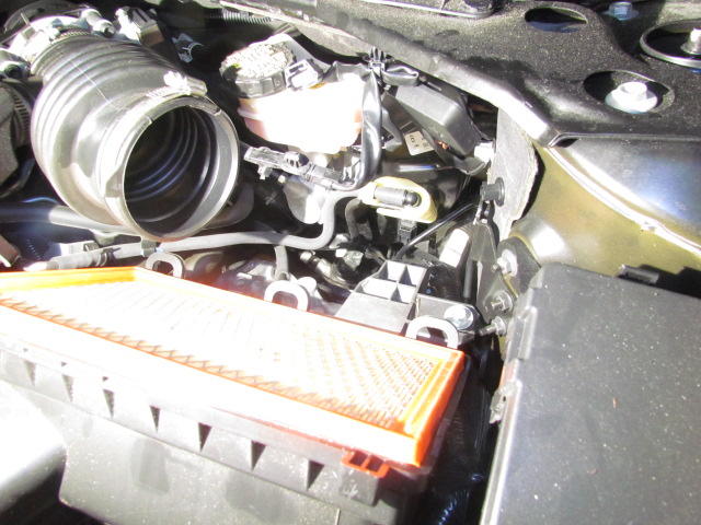
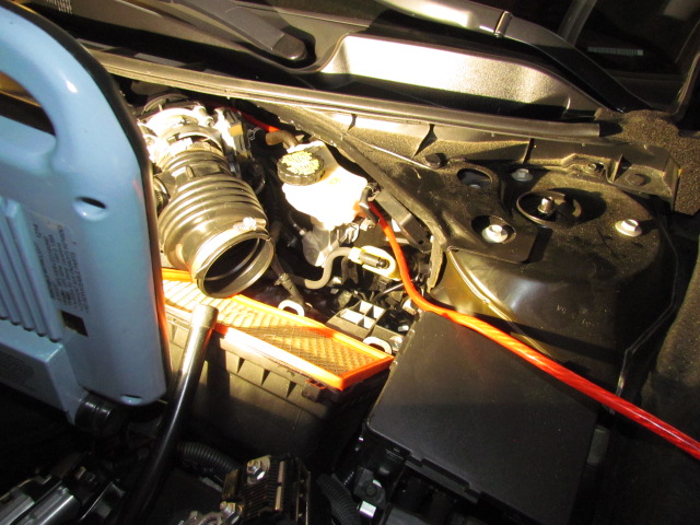
And a photo of the engine compartment showing the air filter removed. I think this will only be important once I find a way though the fire wall and need to use zip ties to run the power cable with the main wire harness.
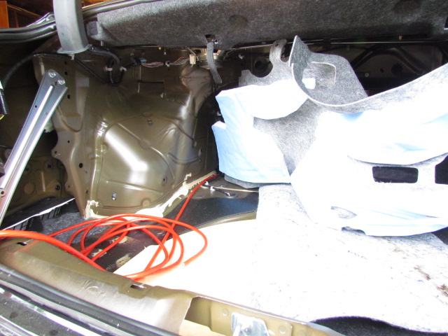
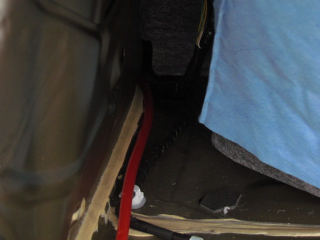
Here are some photos of the trunk showing where the cables come through, and where I’m hiding them for now.
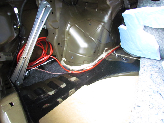
Now that I know how to get the back seat out, I lifted the rear deck finisher. Thank you YouTube. I’m sure I’m the only one that didn’t know about the black webbing tabs in the trunk that released the back seats to fold down; one for the driver’s side and one for the passenger’s side. To get the rear deck out:
The flange for the rear deck speakers is different than the flange for the front door speakers, so I’ll have to make two new adapters. I should have looked at Tommie70’s post a little closer.
You can see from the photos how much room you have to pull wires once the trunk and back seat are stripped. I’ve also verified, at least for myself, that there’s enough room behind the trunk side finishers for DSP units and amplifiers, in case you want everything hidden.
In the photos you can see the various wires routed into the trunk to their temporary hiding places. You’ll notice I repulled the wires. More about that next.
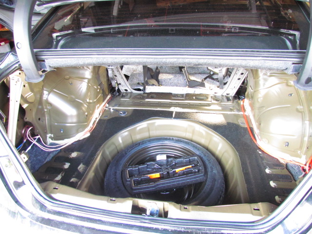
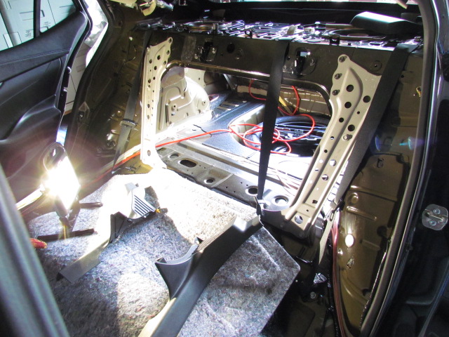
I decided to reroute the power cable through the cable chase along the passenger side under the sill trim pieces so I could take advantage of the unused fire wall penetration behind the glove box. The glove box is simple to remove: eight screws and pull gently but firmly straight out. Be careful of the harness for the glove box light and the trunk release cancel switch.
The fire wall penetration is slightly above the glove box on the right side, behind the “wool” insulation. There’s a grommet there, sized perfectly for 4ga wire. I doubt there’s room in that hole for 1/0 cable plus a grommet to protect the cable.
I’ve posted the photos in this order:
I haven’t connected to the battery yet. I don’t want voltage on the cable until I have a place to connect the other end. No, my power cable is not hanging out from under the hood; it’s wrapped around the fuse box and zip tied in place.
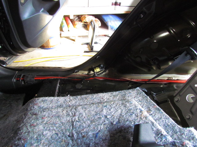
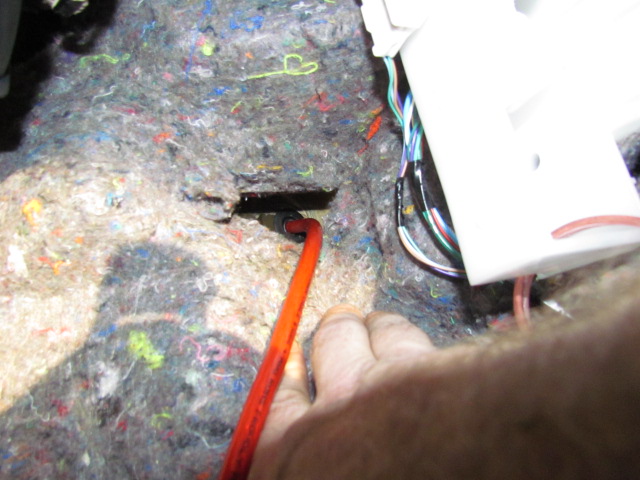
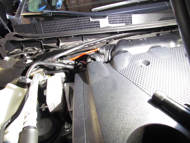
Since I moved the power cable to the passenger side, I also moved the new cables for the high level output from the factory head unit to the driver’s side. The route is the same as the speaker cable, so I didn’t post any more photos. Eventually, under the dash and to the back side of the head unit for connection.
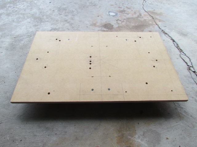
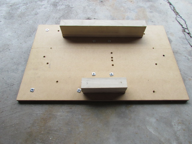
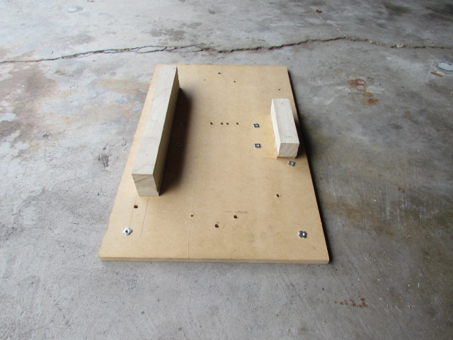
Next step: amp boards: one for amplifiers and one for DSP units. The DSP board will be simple, the amp board more difficult.
OK, that SUCKED! The amp board kick my… I figured on five hours, it took nine. Holy cow. I won’t be doing that again.
I simply had to have my amp under the rear deck and I figured a basic amp board wouldn’t be too complicated. The root cause of all the trouble is the number of protrusions on the underside of the rear deck. It isn’t flat. There are the trunk light (which I’ll eventually replace), the seat back release cables, the plastic studs that hold the rear deck finisher on, etc., etc. Complicating matters is the torsion spring for the trunk lid; it moves a lot as the trunk lid is opened and closed restricting where I could install bolts to hold the amp board up.
I had originally planned to suspend my amp board from long bolts, but changed plans and made some stand-offs so I could tighten the amp board against the underside of the rear deck.
I ended up using three existing holes in the rear deck and drilling two new holes. I wish I had figured out a way to have the mounting bolts for the amp board clear of the amp, that would have made things much easier to install. But two of the bolts are under the amp, so I had to install the board first, then the amp while lying on my back in the trunk.
My board is over-size because I’m trying to figure out a way to install a second amp to power woofers, so I am accommodating that at this time. I’d prefer for the woofers to be in the cabin rather than trunk-mounted, but we’ll see.
The moral of the story is perhaps Tommie70 had it right, install amplifiers against the rear fender wells.
I couldn’t have finished this part without help from my son, so, thanks to macdonsa.
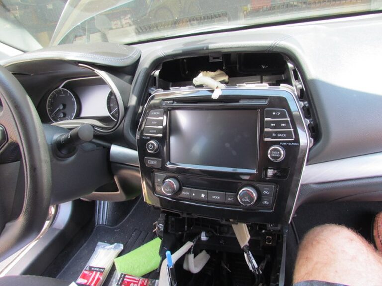
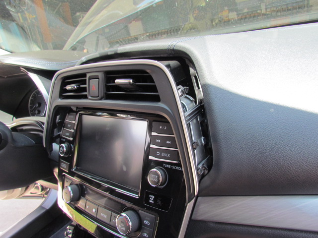
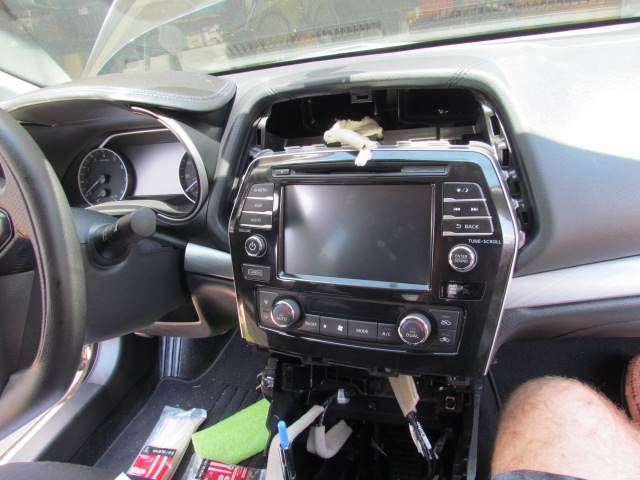
While I’m waiting for my DSP unit to be delivered, I took the head unit out and verified which wires need to be cut to tie in my new signal wires. Everything came out fairly easily.
The shift knob comes off easily. Follow the service manual recommendation and shift the car into neutral first to the shift lever slides in and out of the “leather” boot easily. The wire clip that holds the shift knob on comes off with a screw driver, then the knob slides off. There’s clear grease all over the shift lever.
The top of the console snaps out next. Start at the end closest to the back seat and work forward. There are a half dozen or so wiring harness connectors to disconnect to get the console out of your way.
You don’t have to pull the “leather” side panels, but I did. There’s an error in the service manual: according to the service manual each piece is held in by one screw plus the clips, but there are two or three screws, depending on which side you’re taking off.
Next is the center A/C vents. The trim piece is shaped like an X-Box controller. Use a trim tool to pry the “horns” out first, then the vents will pop out. Careful, there’s a harness for the HAZARD light button.
Now you can get to the four screws (two top and two bottom) holding the head unit in. Once the screws are removed I put my hand behind the unit and pulled it out. I wrapped it in a towel to keep the sharp brackets from scratching the rest of trim while I disconnected the various harnesses.
There’s a photo showing how much space there is behind the head unit. The biggest problem I’ll have routing wires behind the dash is finding something suitable to secure them to.
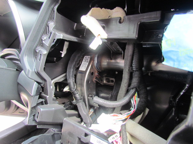
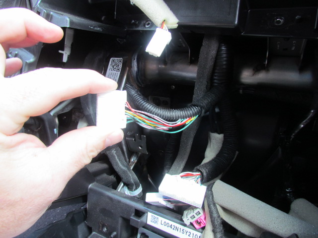
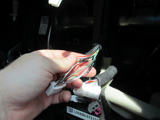
I’ve posted a couple of photos of the harness that has the outputs from the head unit to the speakers. I’ll tie in here for my new wires. The wiring is encased in a tar-coated felt tape and plastic loom. As you can see, I removed some of the felt tape to open the loom for access to the individual wires. I hope you can see in one of the photos that the wires for the speakers have black electrical tape on them. Your car might not, but mine did.
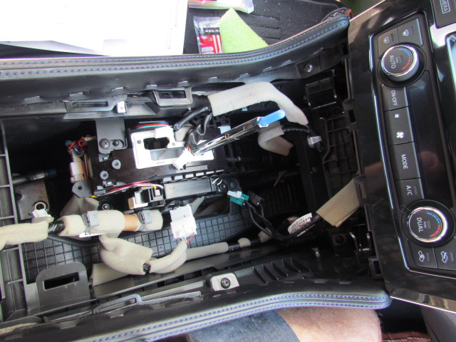
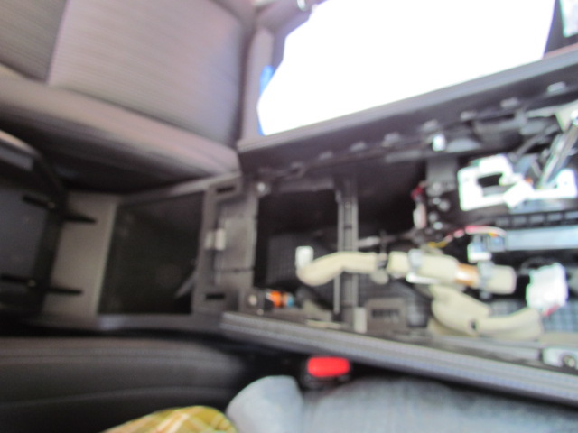
Here are a couple of photos of the inside of the center console. There is enough room in there, I think for DSP, mini-amps, radar detectors and laser detectors. The first photo is looking forward toward the dash, the second backward toward the back seat.
In the front half I think there’s room next to the shift lever assembly forward of where the cup holders are. That long strip with the “checker board” pattern is the air conditioning duct for the back seats. Between the gear shift lever assembly and the big well under the center arm rest is a pretty big cavern that could house electronics.
I found some errors in the Factory Service Manual:
Section IP-20: The figure for the Center Console Finisher (LH) and (RH) show one screw and five clips holding each finisher in. There are two screws for the LH and three screws for the RH finisher.
Section AV-183: The diagram shows the A/C switch assembly located above the A/V control unit (the factory head unit), but in my 2016, the A/C switch unit is below the head unit. It also comes out with the head unit, no need to remove it separately.
Section AV-44: The “physical values” table does not include connections 13-18. If you skip forward to page AV-62 you can see the pin-out for connector M-160, which has the output connections for the head unit. 2&3 are the front left speakers, 4&5 are rear left speakers, 11&12 are front right speakers, 13&14 are right rear speakers.
I’ve rung out pairs 11/12 and 13/14 and confirmed those. I’ll ring out 2/3 and 4/5 before cutting them when it’s time to install speakers.
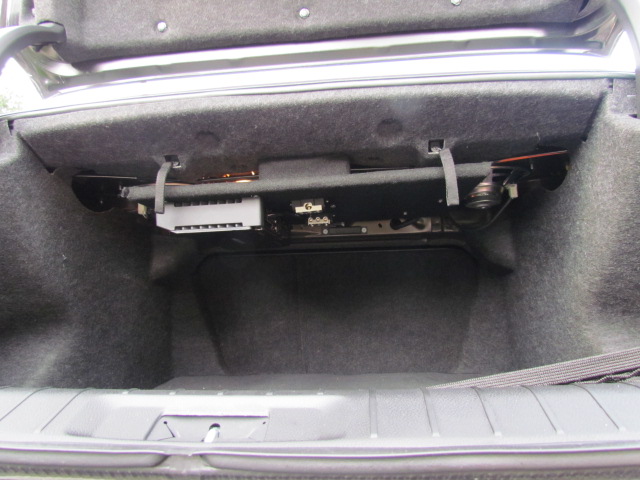
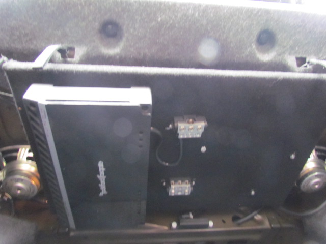
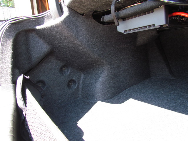
Oops, I was wrong when I posted there is plenty of room behind the trunk finishers. In the first photo, you’ll see the left side trunk finisher installed. The left side, with the plastic fasteners, installs directly against the inside of the body panel. No room back there. The right side of the finisher covers up the fender well. There seems to be plenty of room back there, but much of the volume is above the fender well and all curvy, not suitable for installing rectangle-shaped audio gear.
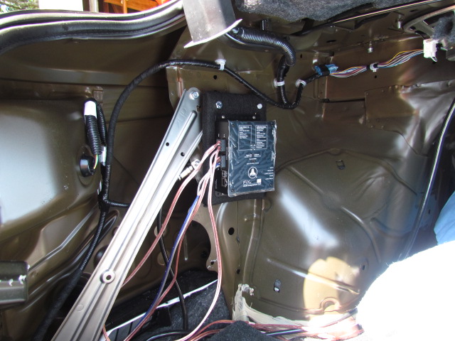
The second photo shows where I installed my FIX-82. I had hoped to get both the FIX-82 and TWK-D8 on the same side, but the TWK-D8 will have to be on the right side of the trunk. The area to the right of the FIX-82 is what I was referring to above, curvy and not suitable for installing audio gear. I ended up using one of the structural bolts that holds that silver diagonal brace in place, as one of the fasteners to hold the FIX82 in place. Those bolts are M8-1.25.
You may be able to see my chassis ground beneath and to the left of the board the FIX-82 is mounted on. It’s located in the triangular space between the right side of that diagonal brace and the FIX-82 board.
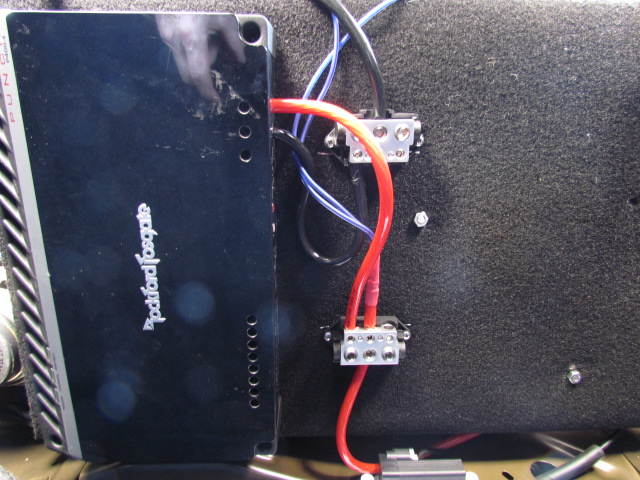
Finally, you can see the power and ground wiring in the third photo. Separate connections for two amps (another four channel amp is in the plan), I’ll power the FIX-82 and TWK-D8 from the same power connection on the distribution block.
I was able to make some incremental progress today: I soldered the pig tails to my mid/woofers to get them ready to install. I also mounted my tweeters in the cover over the side-view mirror mounts.
The first photo is the closest I have to a “before” picture. Sorry.
Then there’s a photo of both finishers with the manufacturer’s “basket” fitted. There may be room in these finishers for after market 1″ tweeters (I’ve read the factory Bose system has 1″ tweeters here), but I don’t know. It’s just about perfect for the 3/4″ tweeters I have. You may be able to see in the photo that I lined the basket with felt, which holds the tweeter in the basket quite well. Three dabs of Gorilla Glue hold the baskets in the finishers. Be careful with that stuff, it “foamed out” from behind the basket and made a mess on the front of the finisher. I found it in time and cleaned it up with mineral spirits.

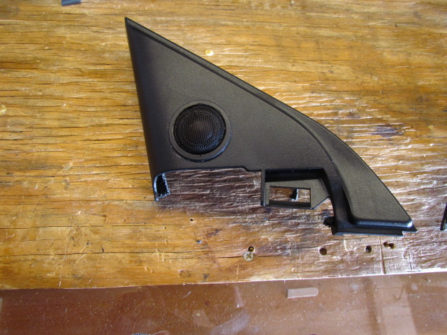
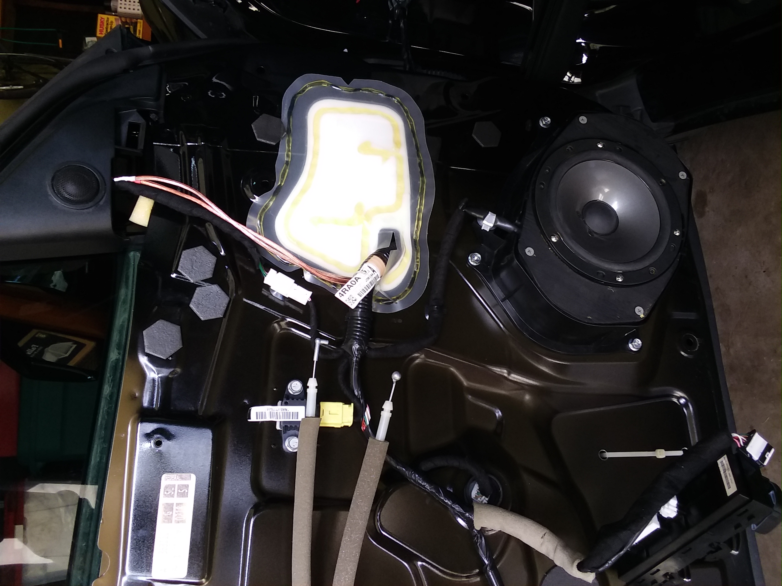
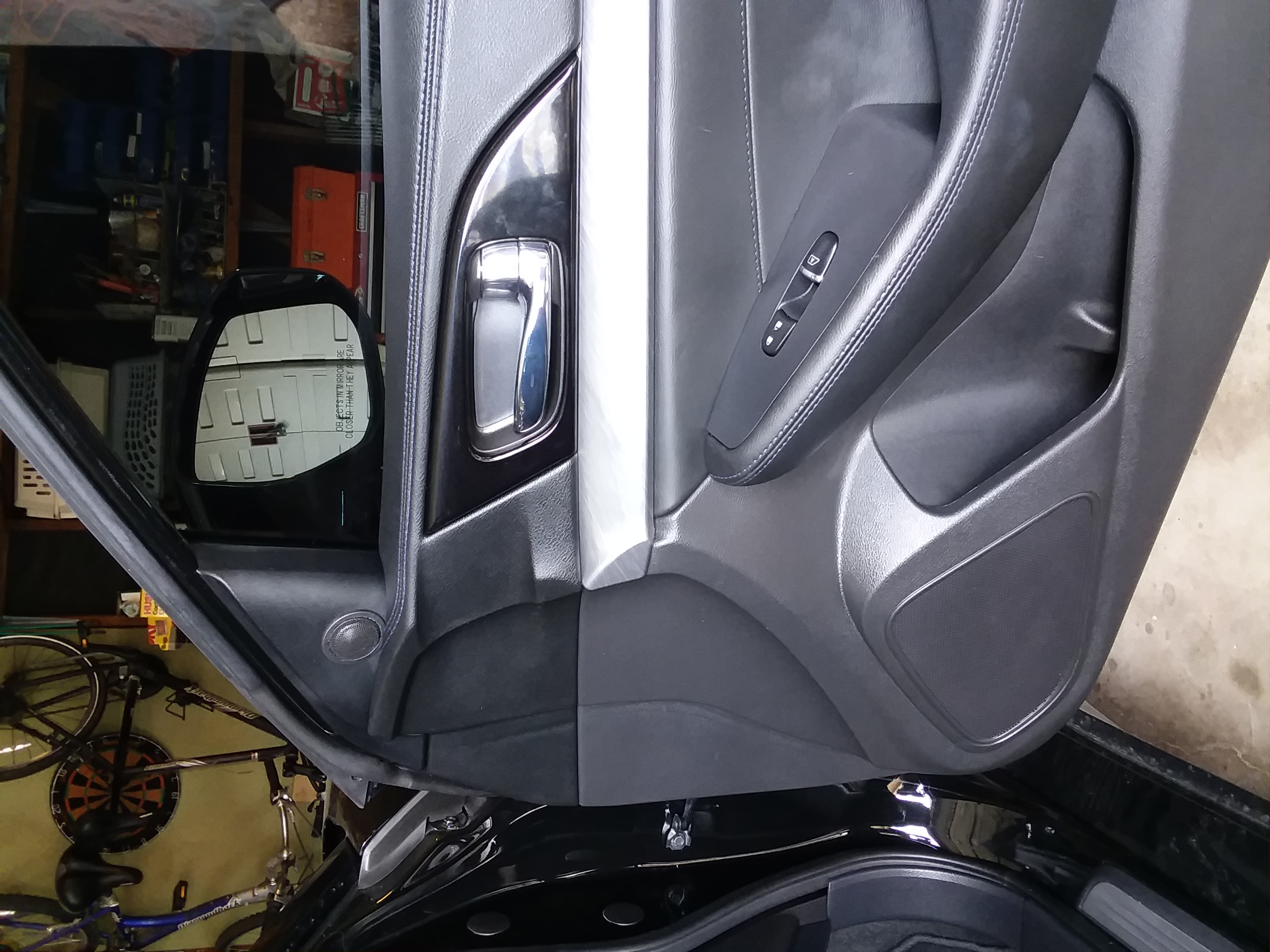
This morning I installed the speakers (mid/woofer and tweeter) in the front doors. Placing the crossover proved harder than I thought and I ended up putting it in a place I had intended not to put it: inside the door. I had originally planned to put the crossover between the door and the finisher, but I couldn’t find a spot that had room enough. Like the trunk finishers, the front door finishers proved tricky for me.
The first photo shows the driver’s door with the finisher off. At the bottom right you can see the 5-1/4″ mid/woofer I salvaged from my previous car. Left of that you can see the white zip-ties I used to secure the crossover inside the door. It does not interfere with the window rolling down in this spot. Above the mid/woofer you can see the wire from the tweeter snaking down to the hole in the plastic barrier to go inside the door to the crossover. For strain relief I used zip ties to secure the tweeter wiring to the factory harness it runs next to in the photo, and also to one of the fasteners inside the mirror finisher.
The second photo shows the passenger door reassembled.
Next step is to install the speakers on the rear deck and wire everything to the amp. I’ll also mount the JL Audio TWK-D8 and connect it. Last step for now is to cut into the factory harness at the head unit to tie everything in.
If you decide to remove the factory head unit, BE CAREFUL! There are two identical connectors back there and if you don’t put them back correctly, you’ll short out a bunch of stuff, blow a bunch of fuses and probably have to take your car to the shop for everything to get reset to factory defaults.
My car is back from the shop with all the blown fuses replaced and all internal computers reset. On the way home, it sounded like only the rear deck speakers (6-1/2″) were working, and full range at that. Still sounded better than the full basic factory system, if a little bass shy.
After dinner I confirmed that all the electronics were powered and ready. I set the “turn on mode” of my FIX-82 to “switched”, then performed the calibration. That was successful. Then I connected my laptop to my TwK-D8 and downloaded the set-up I had made. It still sounded like only the rear deck speakers were working, full range. I couldn’t hear any sound from the front speakers, but when I held my hand in front of the mid-woofers, I could feel them working. I’d connected the outputs of the TwK-D8 to the amp backward. After switching the RCAs everything was right with the world.
So now it’s time to sit back and enjoy much improved sound and do some tweaking (input levels to the amp, equalizers, etc.).
Phase 2 more amp channels, Phase 3 replacing rear door speakers, Phase 4 either Dynamat or bigger rear deck speakers. But that has to wait for a few months.
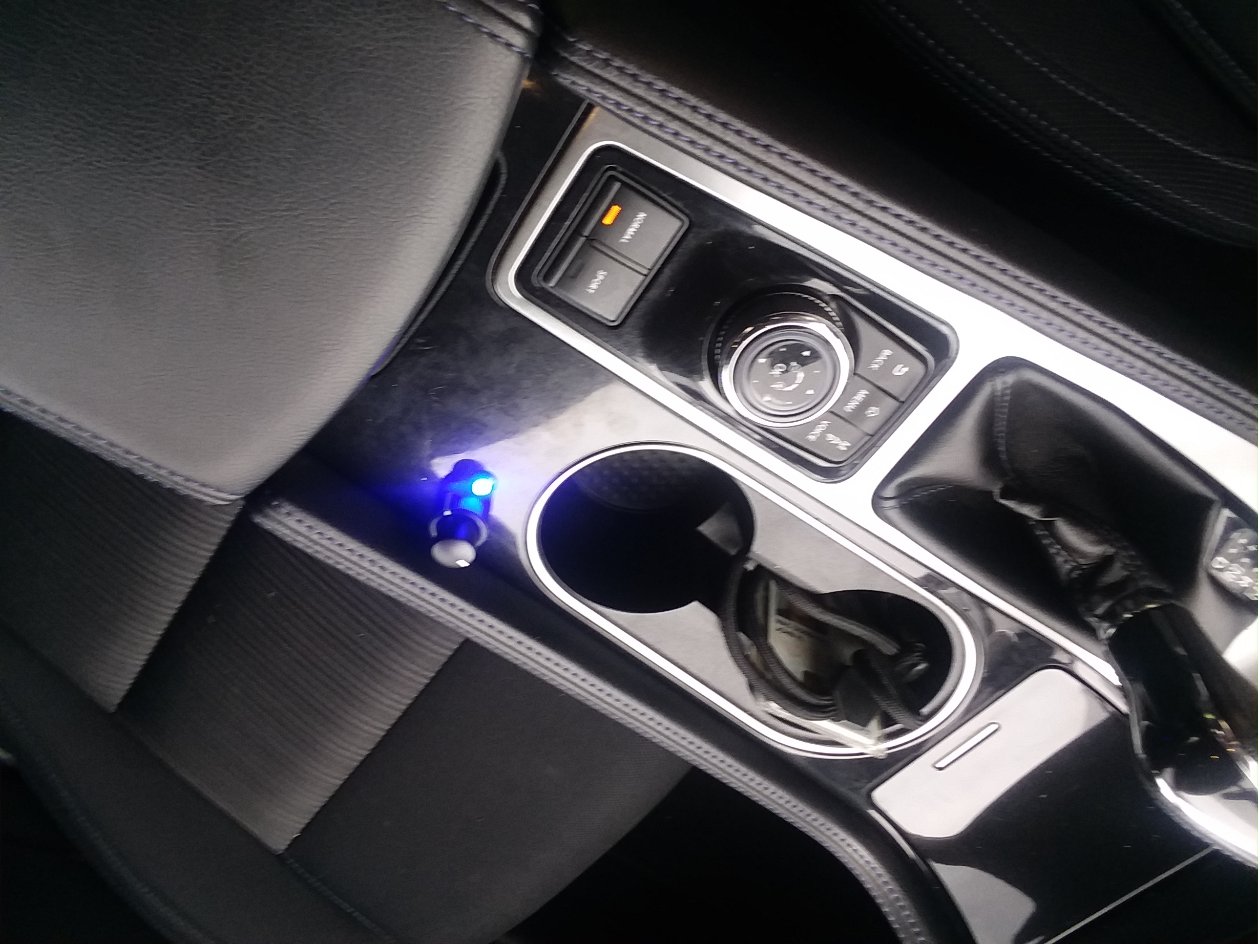
Just because, I decided to install the DRC-200 that came with my TwK-D8. The DRC-200 (Digital Remote Control) is a three-function remote: volume, preset selector, user-defined function. The volume function bypasses whatever speed-sensitive tone controls are in the factory head unit keeping the volume adjustment linear. The preset selector allows you to select any of the six preset configurations (signal routing, crossovers, equalization, signal boost/cut, delay) that can be stored in the TwK. The user-defined function can be sub level, fade/ balance or a couple of other functions. Details at JL Audio’s website.
I ran the cable from the TwK-D8, behind the right rear fender well in the trunk, into the center console. Unfortunately, the “during” photos I took got deleted, so you’ll have to settle for my description. I ran the cable behind the right side trunk finisher, then under the trunk floor mats to the back seat. Once out from under the trunk floor mats, I went under the rear seat back and under the rear seat cushion. I then fished the cable under carpet to the back of the center console. The rear of the console simply pops off, exposing plenty of room to route the cable. Then I fished the cable through the console, under the bin in the back of the console.
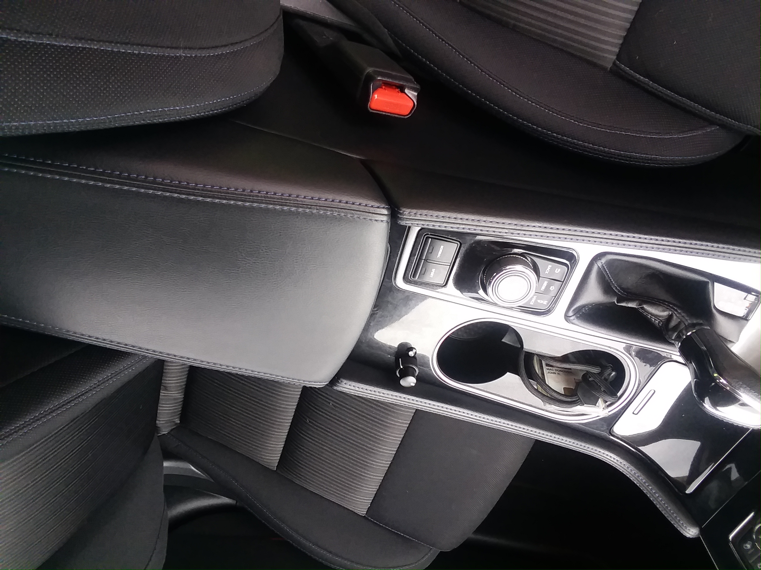
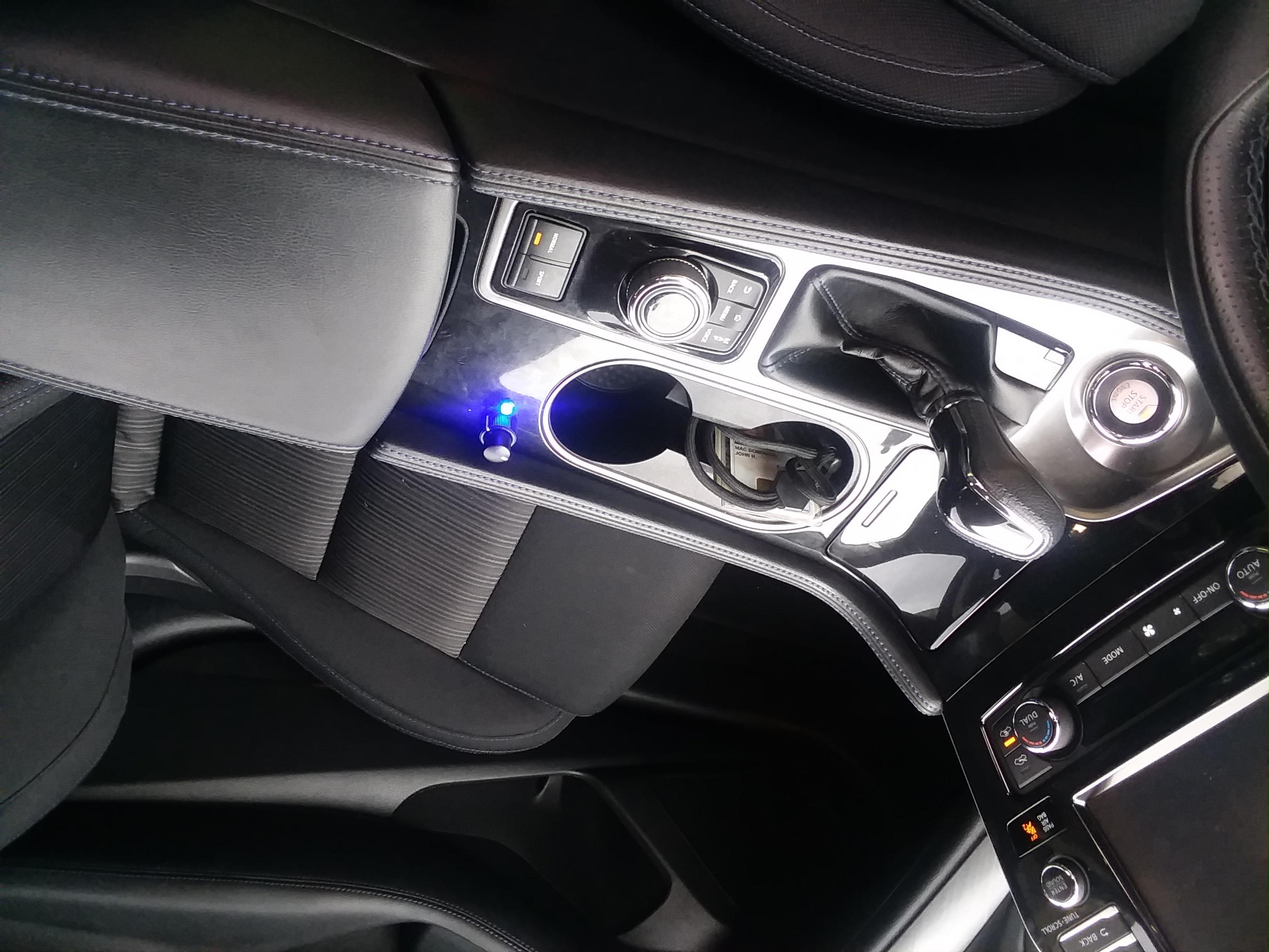
Now you can see in the photos I do have where I installed my DRC-200: behind the cup holder and in front of the console bin. Actually, the first photo I posted shows where I wanted to mount the DRC-200 at first, next to the trunk release button, with the indicator light in the silvery tri piece next to the trip odometer reset button just above. However, I realized what that would mean for a left-handed driver like me: lots of time taking my hand off the wheel to adjust volume.
The other pictures posted show where I did mount the control and LED. I really wanted it 4″ forward (that’s where my hand naturally lays), but that’s where the cup holder is, so there you go.

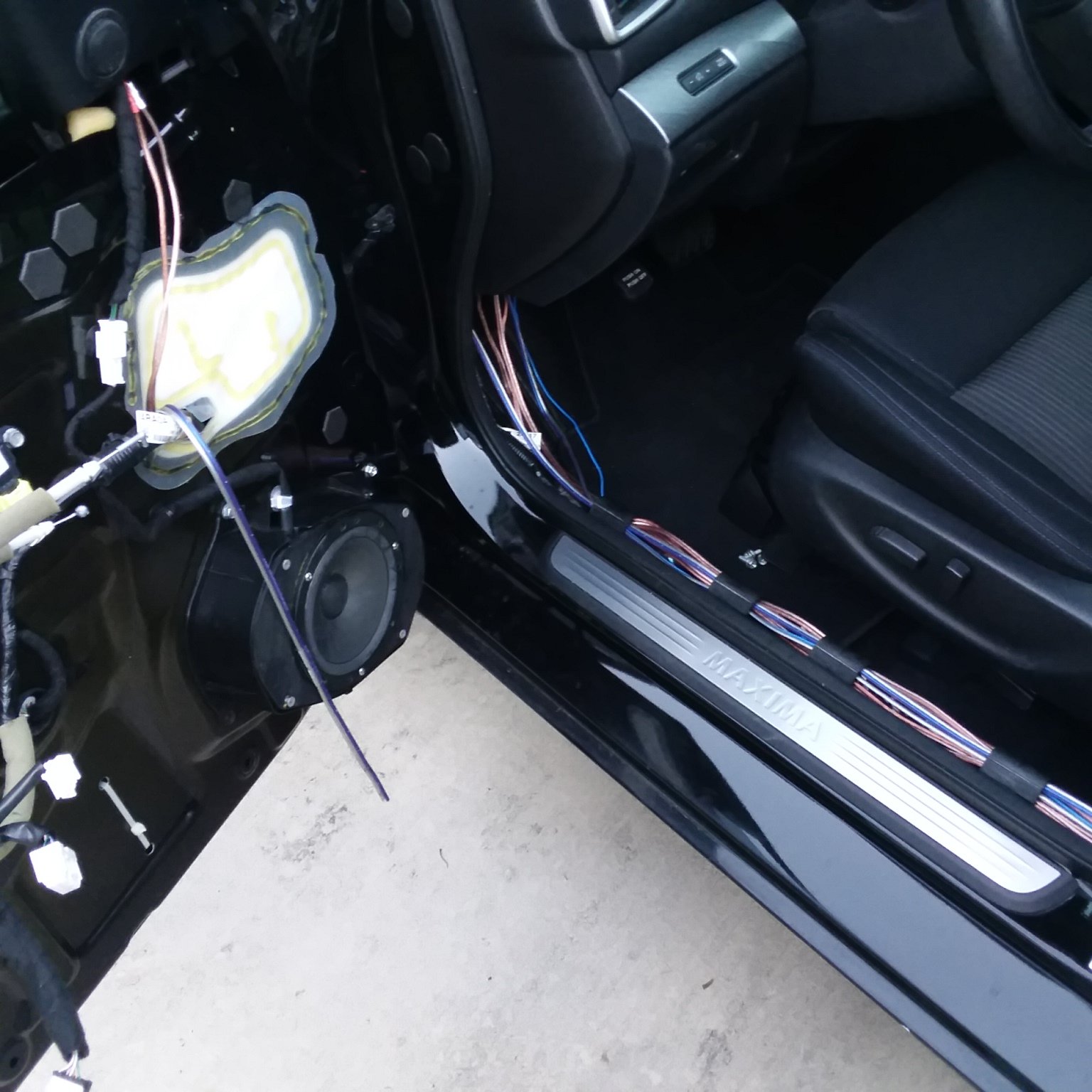 That dangling wire is the new wire for the tweeter.