Tag

Interior, Exterior & Lighting

Browsing

Member Credit: tigersharkdude

These is a full list of LED replacements bulbs for your 1995-1999 Nissan Maxima.

Tools Needed:

  1. Phillips Head Screw Driver
  2. Thin flat head screw driver
  3. Plastic Trim removal tool
  4. Extending magnetic pickup tool
  5. POSSIBLY 10mm socket and ratchet
  6. POSSIBLY a headlamp light

LEDs:

Map Light – 20 SMD LED Panel with a BA9s Adapter(can be purchased from your choice of supplier, I prefer ebay because they tend to be just as good and are usually $2-3 each)

Cars with 2 Map lights will need TWO 12 SMD LED Panels and 2 BA9s adapters (can be purchased from your choice of supplier, I prefer ebay because they tend to be just as good and are usually $2-3 each).

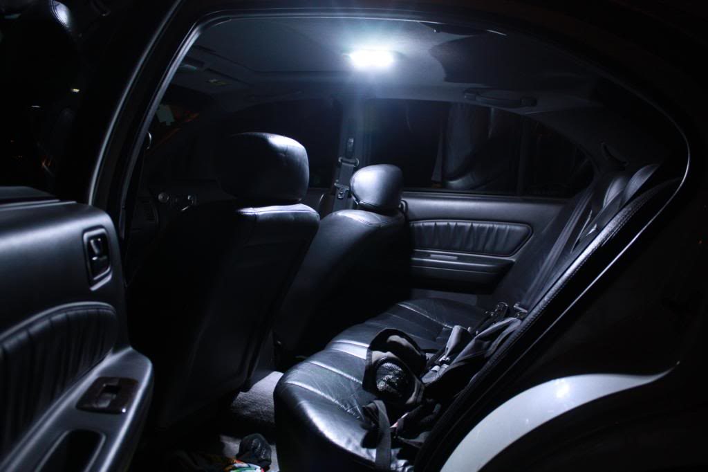
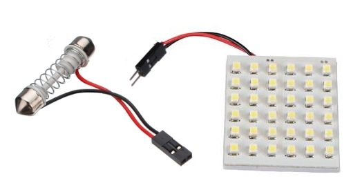
DomeLight – 36 SMD LED Panel with a Festoon Adapter (can be purchased from your choice of supplier, I prefer ebay because they tend to be just as good and are usually $2-3 each).
Door Courtesy Lights – 2 x 12 SMD LED Panel and 2 T10 adapters(can be purchased from your choice of supplier, I prefer ebay because they tend to be just as good and are usually $2-3 each).
Cluster Bulbs:

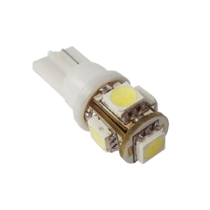
**95-97 cars – 5 (Five) T10/194 bulbs (can be purchased from your choice of supplier). For these I recommend that you use at least 5+ SMD LED’s because if you use something with one LED it will look awful and have a huge hotspot.
**98-99 cars – 5 (Ffive) NEOx 5mm Bulbs ($1.79 Each http://www.superbrightleds.com/morei…panel-led/221/)
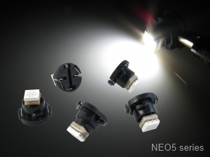
ACC Bulbs: THESE ARE ONLY FOR DIGITAL UNITS. NEOx 4mm bulbs ($2.29 each

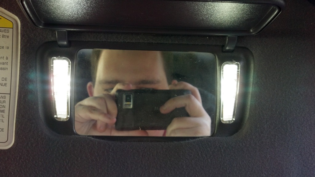
Vanity Mirror Bulbs: 31mm Vanity 3 SMD LED bulb xenon white ($2.49 each http://www.wardenjp.com/stores/festoon.html) or from your choice of supplier)
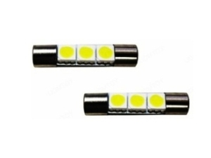
REMEMBER that there are several types of LED panels that are available to purchase, 5050 SMD LED are one of the brightest options that you have. Also remember that LED’s come in a wide array of colors, be sure to always check that the LED that you are looking at is the correct color that you want.

Installation Time: 

  1. Map Light – Approximately 5 minutes
  2. Dome Light – Approximately 5 minutes
  3. Door Courtesy Lights – Approximately 5 minutes
  4. Cluster Bulbs – Depending on your level of experience 30-60 minutes
  5. ACC Bulbs – Depending on your level of experience 30-60 minutes
  6. Vanity Mirror bulbs – Approximately 5 minutes

Note: You can swap pretty much everything from sitting in the front seats. I took the ACC in my garage when I swapped those bulbs as there are 4 small screws that I didn’t want to lose.

Installation Process:

Map Light:
Installation of the Map light is fairly straightforward. Some cars have 2 Map lights for those you will need to remove/install both sides

  1. Step One – Use your trim tool to remove the lense(s) from your Map light. This is done by inserting the sharp/pointed end of the tool into the grove near the front of the lense(s) and popping the lense out
  2. Step Two – Remove the old bulb(s). This is done by grasping the bulb(s), push down/in, and rotating counter clockwise and pull it out.
  3. Step Three – Installing the LED(s) is fairly simple. For the cars with 2 bulbs, the map lights will be plug and play. But the cars with one map light, they are trickier. Because of the way that the Map light bulb-base is wired, you can not simply plug in a standard LED bulb and expect it to work. I opt for LED board(s) that have a wired connection between the bulb-base and the panel. To make the LED board(s) light up you will need to connect the connection like so ..
    Positive>>>Negative
    Negative>>>PositiveThis will need to be done because Nissan wired the bulb-base in “reverse” and not what is commonly used. IIRC, Instead of getting power from the center contact, it gets power from the socket wall. And visa versa for the ground. Connect the LED board to the BA9s adapter and plug the adapter into the bulb socket (insert the adapter into the socket, push it in and turn clockwise [so that you lock the adapter in place]).
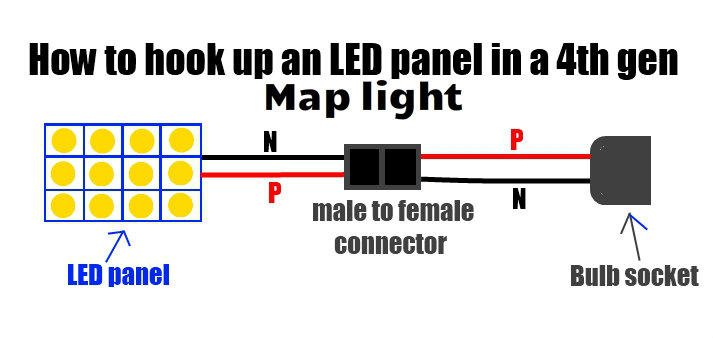
  4. Step Four- If the panel is not lighting up when you plug the LED board in and press the “on” button, then you will need to remove the bulb base and turn it 180° as the socket is polarized and will only work in one direction. *** Note if you have followed all of the above steps and the LED board is still not working, check to see if your Interior Illumination fuse has popped.

Dome Light:
Installation of the Dome light is fairly straightforward

  1. Step One – Use your trim tool to remove the lense from your Dome light. This is done by inserting the sharp/pointed end of the tool into the grove near the front of the lense and popping the lense out
  2. Step Two – Remove the old bulb. This is done by grasping the bulb, and rotate it counter clockwise and pull it out.
  3. Step Three – Installing the LED. First connect the LED panel to the Festoon adapter. Unlike the Map light, this is simply plug-and-play (+ to +, – to -). Connect the LED board to the Festoon adapter and plug the adapter into the bulb socket (squeeze the adapter together and plug it into the socket)
  4. Step Four- If the panel is not lighting up when you plug the LED board in and turn it “on”, then you will need to remove the festoon adapter and turn it 180° as the socket is polarized and will only work in one direction. *** Note if you have followed all of the above steps and the LED board is still not working, check to see if your Interior Illumination fuse has popped.

Door Courtesy Lights
Installation of the Door Courtesy Light (DCL) is fairly straightforward

  1. Step One – Use your trim tool to remove the lense from your DCL. This is done by inserting the sharp/pointed end of the tool into the grove near the front of the lense and popping the lense out
  2. Step Two – Remove the old bulb. This is done by grasping the bulb, and pulling straight out of the socket
  3. Step Three – Installing the LED. First connect the LED panel to the T10 adapter. Unlike the Map light, this is simply plug-and-play (+ to +, – to -). Connect the LED board to the T10 adapter and plug the adapter into the bulb socket.
  4. Step Four- If the panel is not lighting up when you plug the LED board in and turn it “on”, then you will need to remove the festoon adapter and turn it 180° as the socket is polarized and will only work in one direction. *** Note if you have followed all of the above steps and the LED board is still not working, check to see if your Interior Illumination fuse has popped.

Cluster Bulbs
Installation of the gauge cluster bulbs is fairly easy, but can be tedious if you have never removed the cluster before. I will say this, be sure to keep the screws in a “secure” place, such as a zip-lock baggy.

  1. Remove the knee bolster from under the steering wheel (two screws will need to be removed, the fuse panel cover, and one electrical connector once you pull the knee bolster down)
  2. Remove the steering column cover (There are 6 screws that are accessible from the bottom of the cover). If you can not access the two screws that are farthest back you may need to remove the metal “cover” that is in the way. This is done by removing the two 10mm bolts and the “cover” should come right off.
    Step Two ½ . Now open the lever on the driver side of the steering column so that you can lower the column down as far as it will go.
  3. Remove the gauge cluster trim CAREFULLY SO AS NOT TO BREAK IT (there are two screws on the top of the bezel and 3 electrical connectors which need to be “un-clipped” in order to remove the bezel)
  4. Next, there are 3 screws that hold the cluster in place. Remove those screws
  5. Next, slide the cluster out. There are 3 electrical plugs in the back of the cluster that will need to be “un-clipped”
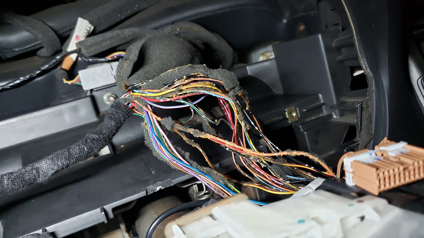
  6.  Once the plugs are “un-clipped” pull the cluster out and you will see the 4 main bulbs on the back side (pic below)
  7. At this step you will be installing the bulbs. Do note that 95-97 cars use different bulbs that 98-99 cars
    95-97 cars/Analog odometer– Remove the 4 main bulbs (they will be larger than the other bulbs), this is done by twisting in a counterclockwise motion and pulling the “socket” out. Now remove the bulb from the socket and insert your car T10 LED bulbs.
    98-99 cars/Digital odometer – Remove the 4 main bulbs and the odometer bulbs, this is done by twisting in a counterclockwise motion and pulling the “socket” out, and put the 5(five) Neo-5 bulbs in the cluster, this is done by inserting the Neo-5 bulbs and turning them with a small flat-head or small phillips head screwdriver).
  8. Take the cluster back to your car and connect the electrical plugs in the back and plug the dimmer switch (on the bezel) back up and test your cluster bulbs. I found a good method of testing these (if it is daytime and you are outside), throw a dark blanket or jacket over you and the gauge cluster and lean close to the close to the cluster and turn the gauge lights on.
  9. If any of your bulbs are not working you will need to turn them around, as they are polarized and will only work in one direction
  10.  Once all 5 bulbs are working, reassemble everything and enjoy what you have accomplished.

Bulbs to Remove

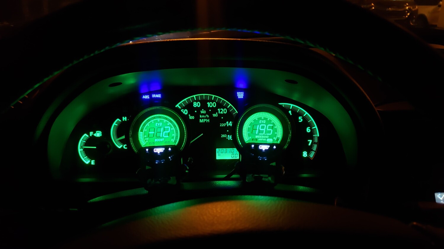
98-99 cluster with COOL WHITE bulbs
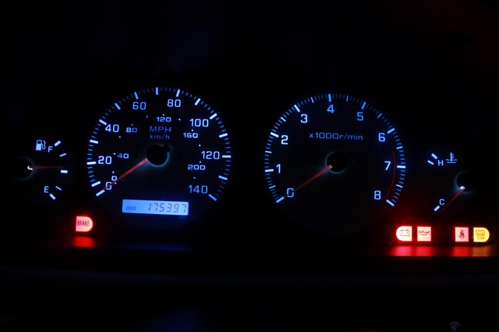
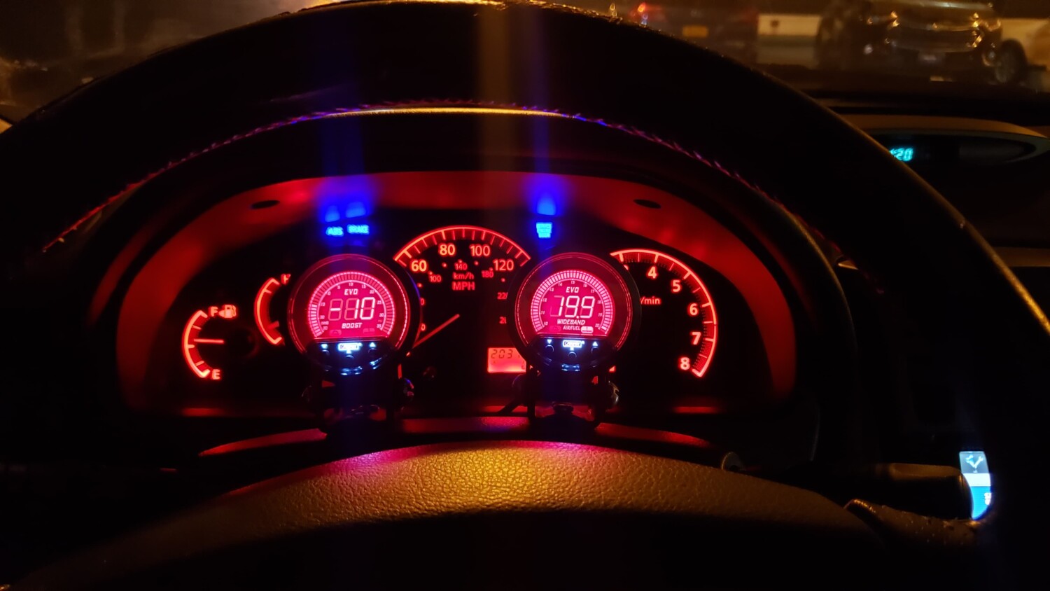
98-99 cluster with RED bulbs

ACC Bulbs:
Installation of the ACC bulbs is a little harder than any of the other swaps mentioned in this How-To. It can be tedious if you have never removed the ACC. I will say this, be sure to keep the screws in a “secure” place, such as a zip-lock baggy.

  1. Remove the waterfall section (shifter trim, AC vents and radio/ACC unit). This is very straightforward, if you need more descriptive information refer to this link ……………….. (insert link)
  2. Remove the ACC by disconnecting the two grey plugs, one white plug and the hose that is attached and the 4 screws holding the ACC in the radio brackets
  3. Once the ACC is removed, you will need to remove the faceplate (attached with clips) from the unit. At this time you can also clean the display face and plastic lens. There are also 4 silver screws around the edge that will need to be removed.
  4. Once the faceplate is off, separate the two pieces (face and back) of the ACC by unclipping the plastic clips. Pull the two pieces apart carefully
  5. You will now have the face and back, the face will have an electric circuit board on the back with 4 twist lock bulbs.
  6. Remove the old bulbs by twisting them counter clockwise and lifting them straight out. Install the new bulbs by inserting them and twisting clockwise to lock them place
  7. Reassemble the ACC unit and take back to car
  8. Before screwing the unit back into the brackets connect the 3 electrical connections and test the ACC to make sure your lights are all working (if any of them are not working you will have to take the ACC apart again and turn the bulbs around as they are polarized and only work in one direction.
  9.  Once all 4 bulbs are working, reassemble everything and enjoy what you have accomplished
    (NOTE: the hot spots aren’t that bad, I had to use a somewhat high ISO to take the pic without a tripod)

Picture exaggerates the hot spots…the camera was at an angle

Vanity Mirror Bulbs:
Installation of the Vanity Mirror Bulbs (VMB) is fairly straightforward. Do note, that some cars do not have lights in their vanity mirrors, for these cars you can skip this section.

  1. Flip open the vanity mirror cover,use your trim tool to remove the lense from your each VMB. This is done by inserting the sharp/pointed end of the tool into the grove near the front of the lense and popping the lense out
  2. Remove the old bulb. This is done by grasping the bulb, and rotate it counter clockwise and pulling them out. Do this for each of the 4 bulbs.
  3. Installing the LED. Insert the 31mm bulb into the bulb socket. This is done by simply pushing in place. Do this for each of the 4 bulbs.
  4. If the bulbs do not light up when you plug the LED board in and turn it “on”, then you will need to remove the bulb(s) that do not light up and turn them 180° as the socket is polarized and will only work in one direction. *** Note if you have followed all of the above steps and the LED board is still not working, check to see if your Interior Illumination fuse has popped

Stock on Left – LED on right

Loading

Community Member Credit: Jose Vargas

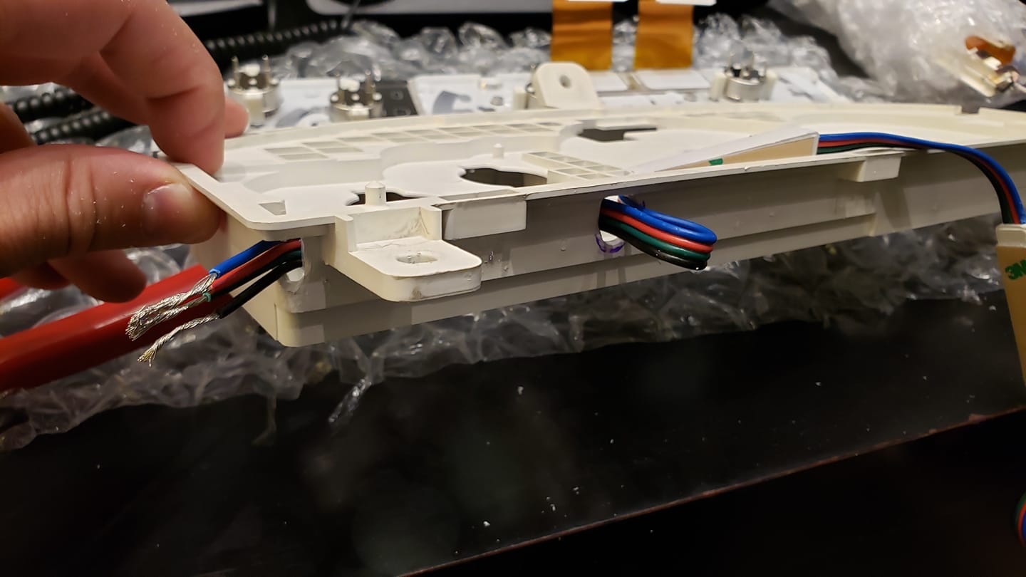
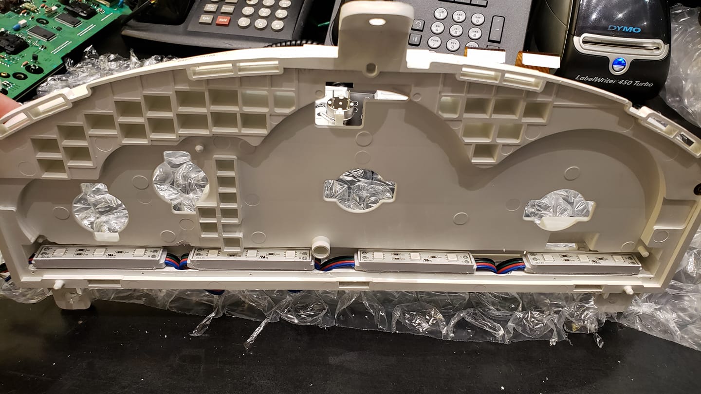
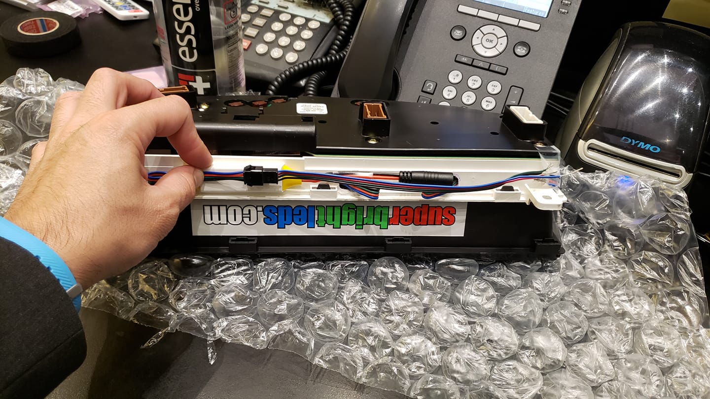
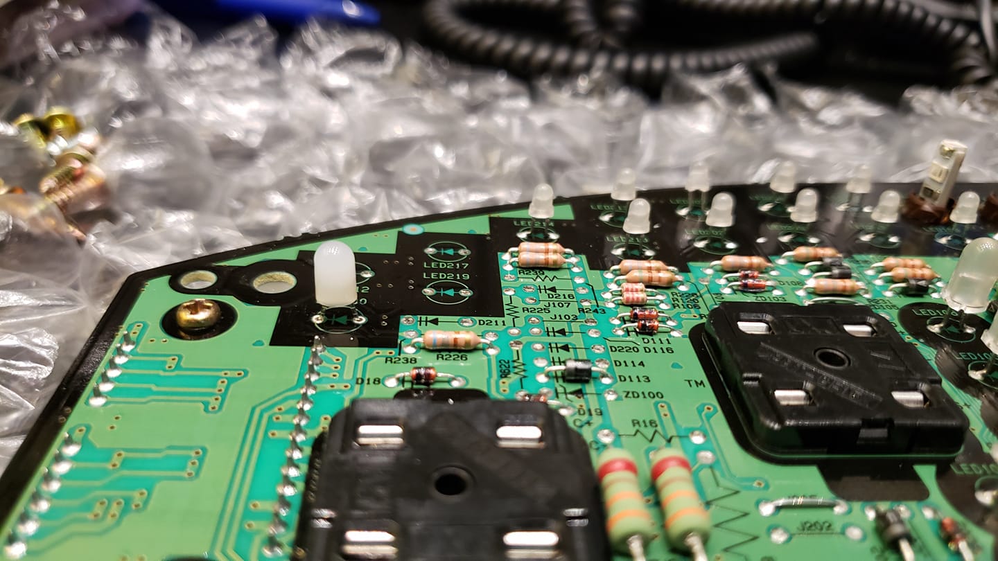
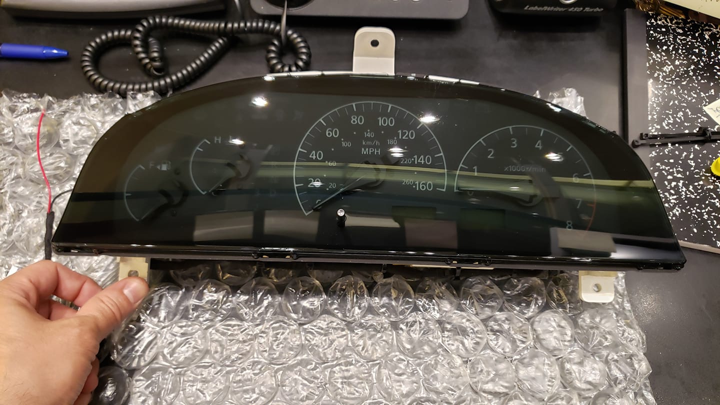
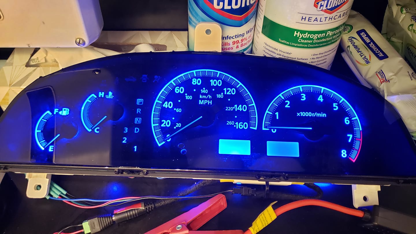
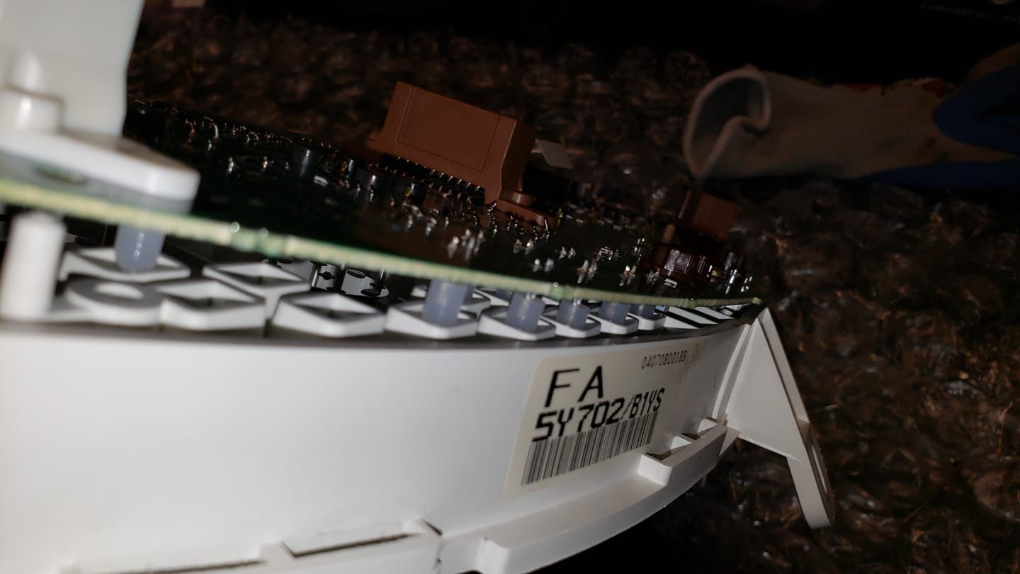
I35 Cluster swap in the process, first ima swap out the long led tub it has to light up gauges and replace it with 4 RGB led strips with the module so I can remotely change to different colors quickly if I want to. Everything PNP like OEM. I’ll post links to what I used to make it perfect…

Has 4 pnp leds that can easily be swapped and for warning indicators you need to unsolder old leds and put in new ones 14 is needed

For the Auto guys you can swap out the shift indicator leds……..3mm for warning indicators,so since the cover and holes for leds is big enough im a swap out the 3mm to 5mm to have it brighter

Without OEM led tube

With oem led tube that lights up entire cluster, so as you see you can run strips

You need 4 strips of these RGB leds

https://www.superbrightleds.com/moreinfo/led-module-strings/rgb-led-modules-linear-modules-w-3-smd-leds-22-lumens/1779/4253

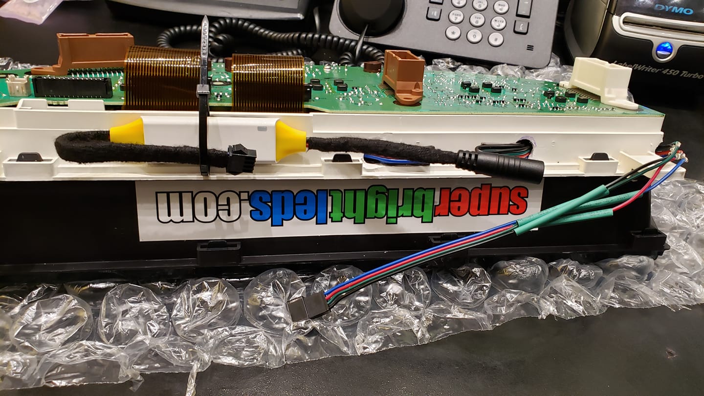
Female……Pigtail connector to make it pnp to module

https://www.superbrightleds.com/moreinfo/bar-strip-connectors/lc4-locking-connector-pigtail-power-cable/1972/4547

Module with remote to change to multiple color

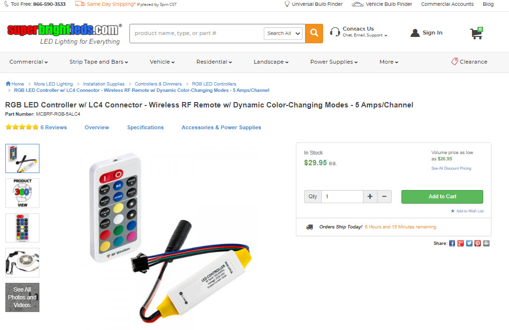
https://www.superbrightleds.com/moreinfo/rgb-led-controllers/rgb-led-controller-w-lc4-connector-wireless-rf-remote-w-dynamic-color-changing-modes-5-amps-channel/3050/6263

Male Power connector to make it pnp, run ground to chassis and power wire with mini add a circuit with 15A fuse to ACC in fuse box

https://www.superbrightleds.com/moreinfo/bar-strip-connectors/cps-f2st-female-standard-barrel-connector-to-screw-terminal-adapter/856/2133

I35 cluster 80% done installed the leds strips. Just waiting for module and pigtail to make it pnp……

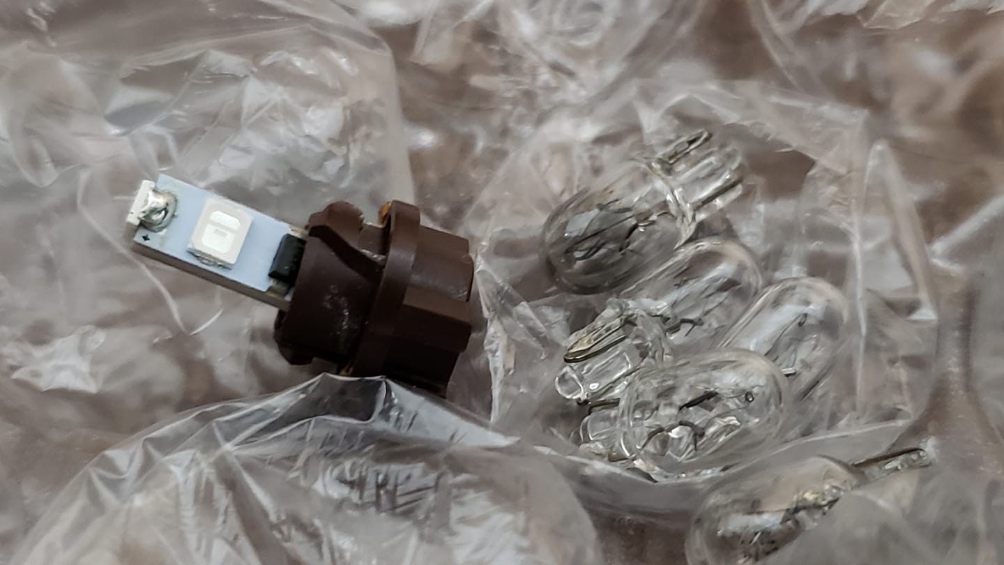
Swapped out the 5 pnp leds

5mm to the left soldered in compared to the small 3mm to the top right

5mm vs 3mm
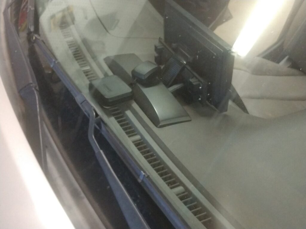
Removed SLIP led so it will not turn on LED213.

Cluster done

Had to dissamble the cluster to put black tape over the AUTO indicators

5MM led clearance

Pnp connector all wired up and ready. Nice and clean…Mr. DoITRightEveyTime.

Cluster is done and installed……mission was a success…..Repinned the plugs and rewrapped harness

1 done 2 plugs left

Wiring mess

3 plugs all wrapped up

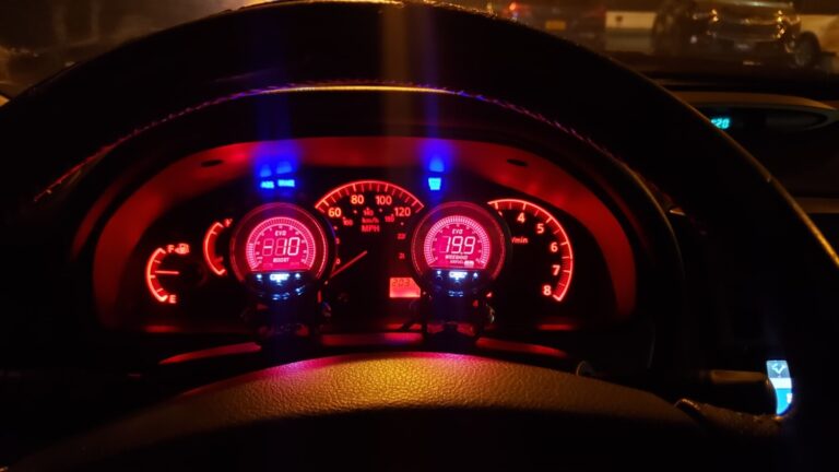
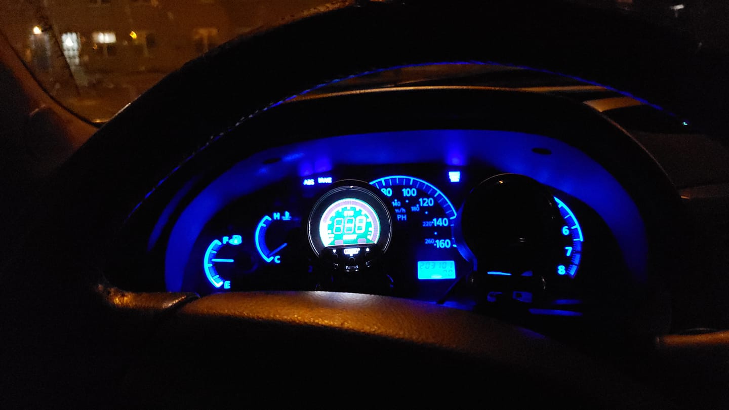
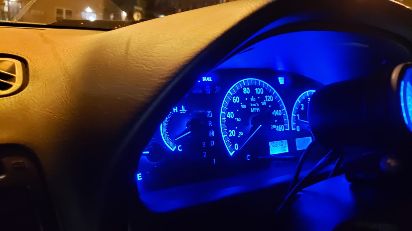
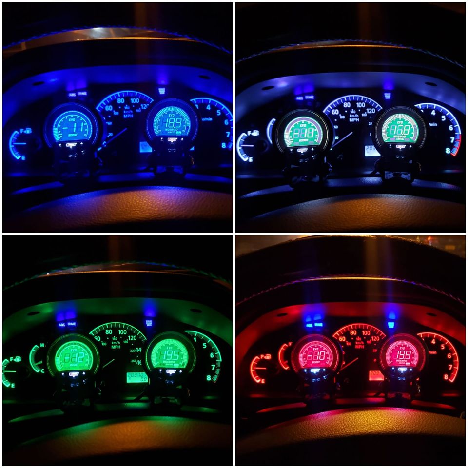
I35 Cluster & Prosport EVO series allows you to match up 4 different colors to cluster..

Loading

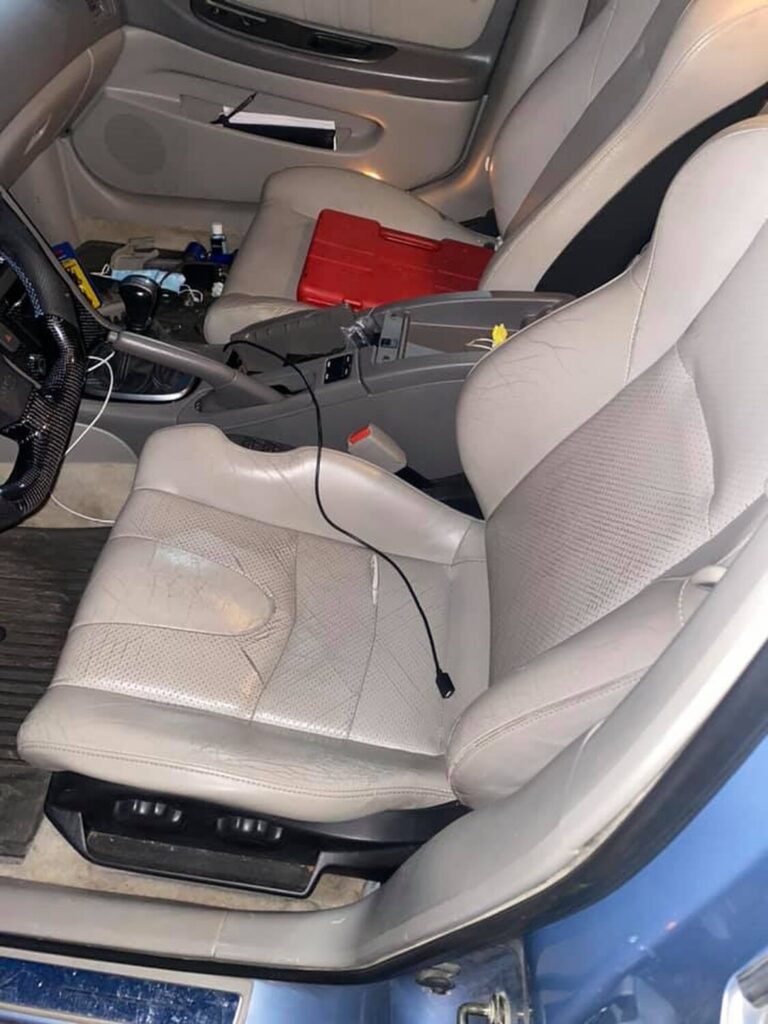
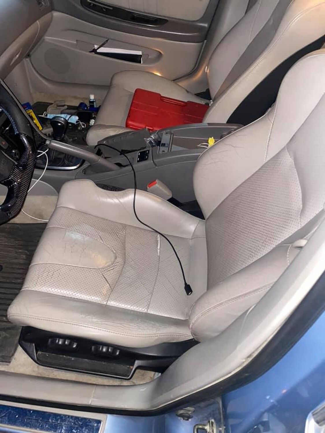
The track width between the 350z and Maxima was the exact same and was key to making this swap work. Also viable, using a seat from a B15 Sentra (00-06) – as these are a direct swap with 5/5.5 Max seats. Also, this guide is only if you have 2 manual front seat rails. All stock Maxima ’02/03 driver seats are power only but some ’00/01 Maxima driver seats are manual…I harvested a manual driver seat from a junkyard ’02 Sentra for the rail.

I studied the tracks for a while to see viable options and this resulted in my final procedure. By changing out the seat brackets my way, I lost about half an inch in sliding backward…not an issue for me and I’m 6’…but I also gained full functionality of the 350z seats. I also chose to go with the manual versions, so if you’re in there looking for wiring help – sorry but no, lighter is better for me.

The main tools you will need:

  • Socket Wrench
  • 10, 12 & 14mm sockets…I believe
  • GOOD drill
  • GOOD drill bits
  • (…and a creative way to cut a bracket. I used a grinder since I had one available.)

Start with the Z seats since they’re most likely not in the car when you’re starting. The process below is the same with the Z and Maxima seats EXCEPT the Z seats have a bracket alongside the inner edge that needs to be cut off. As seen here:

You’ll want to remove the seat cushions and back to make it easier…and to keep the fabric from getting possibly messed up. There are 4 bolts on the seat bottoms near the corners that need to be removed. The seatback has 2 bolts on either side that need to be removed. Once those are out the back comes off easily.

Now, the seats roll on a couple of rolling brackets, one in the front and one halfway down. The object of the drilling is to remove any kind of resistance the factory created in the rails to prevent the seats from rolling too far forward/backward.

There is a single aluminum welded bolt that can be drilled through on both rails in the front. These are present on the Maxima and the Z seats.

Once that is out of the way, you’ll see some ‘dimples’ in the rails. I believe my other set of rails had 6 total but these Maxima rails show 4 total. Drill those out.

Again, the main objective is to remove anything that will keep the rolling brackets from rolling too far forward. Once you have the front welded bolt and dimples out, you may notice it takes a little bit of force to get the rails to slide the rest of the way off. I found that the dimples actually still had a little bit of a ‘bump’ that needed to be removed.

The Z bracket on the side will still need to be removed before you can get to the dimples that it covers. If you don’t have a grinder I guess a Dremel would work, just very time-consuming. You could also take it to a muffler shop and ask to have someone safely cut the bracket off. Remember you still need the rails.

Once you’ve drilled all that out, the rails should slide off. Keep in mind the rolling brackets will come off. They aren’t hard at all to slide back on, you’ll see what I’m talking about when you’re there. To finish things off, you’ll need to transfer the seat belt lock from the Maxima seat to the Z seat. Just a simple bolt holds it on. (The Z seat belt lock doesn’t fit the Maxima seat belt)

Anyway, that’s pretty much it. When you have the Maxima rails onto the 350z tracks then it’s the 4 bolts to put the cushion back on and 4 bolts for the seatback. One last couple of notes, I lost the ability to raise/lower the driver seat…I don’t really care but some people might. Also, you CANNOT use the Z seat trim on the bottom NOR the Maxima seat trim. I’m not aesthetic so IDGAF what it looked like, the seats are comfortable as he11 to me.

Additional Note: 

If you have an ’02/03 Maxima driver seat then you’ll see its power. I ended up using a Sentra manual driver’s seat so I can’t help with that. Some ’00/01 Maximas came stock with manual seats as well, thanks MONTE 01&97 SE!. The power seat has a different setup, with a bolt that holds the rail on the motor ‘screw’ device on either side (see next pic). I’m sure there’s a way around it, I just didn’t deal with it. A driver-side manual Sentra rail from the junkyard cost me a whopping $30 so it was a non-issue to me.

Loading

Community Member Credit: BOOTZ

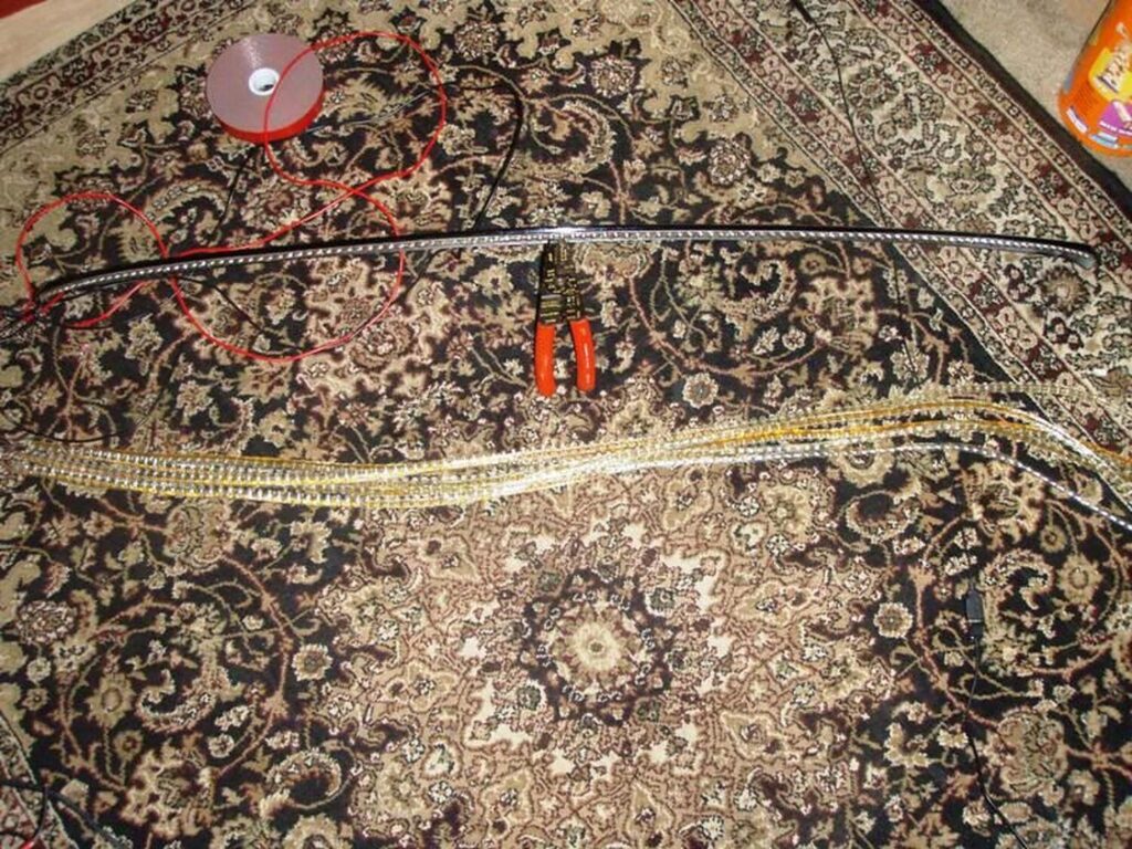
So this was done using a red waterproof 120cm strip from eBay. Make sure you measure to be sure.

Description: 2pcs Red 120cm LED Side-emitting Shine Strips Side Glow Flexible Neon Brake lamp
Order Link: https://www.ebay.com/itm/272474776774
Price: $12.25 (Shipped)

Instructions:

I started out by removing the driver’s side rear window molding. There is one 10mm bolt you have to remove and only visible when you open the trunk.

Once that is removed start prying upwards on the molding starting from the bottom and working your way up. There are about four clips holding it on. Be careful not to put too much pressure on the window or the body of the car. Don’t want to break glass or dent anything.

Once off should look like so….

Then take you led strip and apply two sided tape to it. I used 3m. You want to clean the led strip really well then I heated up the led and the tape before applying it. Did the same on the window. Cleaned it really well and heated it up.

Before applying the led to the window I set the roof spoiler in position and placed a small piece of the led underneath to see where i could place it without getting in the way of mounting the spoiler. Turned out to be maybe 1/2″ from the top of the window.

Also before applying, make sure your wires are running down the driver’s side. That is where the rubber boot is where the wires will run in.

You are then able to run the wires down towards the rubber boot going into the vehicle. I just tucked them under the window. The molding will cover it up anyway.

From here you can tap into the existing wires to the factory 3rd brake light (6.5 gens). If you don’t have the factory spoiler with 3rd brake light wires should be the same colors found in harness running towards the front of the vehicle.

If you pull up on the boot you can find your wires there.
12v – Red/Green
Ground – Black

From here you should be able to mount your roof spoiler and reassemble everything.
Here you can see they are pretty hidden unless you really look for them.

Night shots…

I also ended up putting a black vinyl overlay on the factory 3rd brake light to make it look like part of the spoiler. You could paint it to match the vehicle’s color if you don’t ever plan on using again.

Additional Reference Photos from DEADBOLT

I 3M taped the strip to the edge of the roof spoiler for it to be more visible.

I cut down the strip to fit exactly the lines of the spoiler and wired an exted + and – wires to it so I can connect it to the interior plug of where the old 3rd brake light use to be.

Test Pics:

Lights off shot:

Video from CHULO

Loading

Community Member Credit: Nissan X

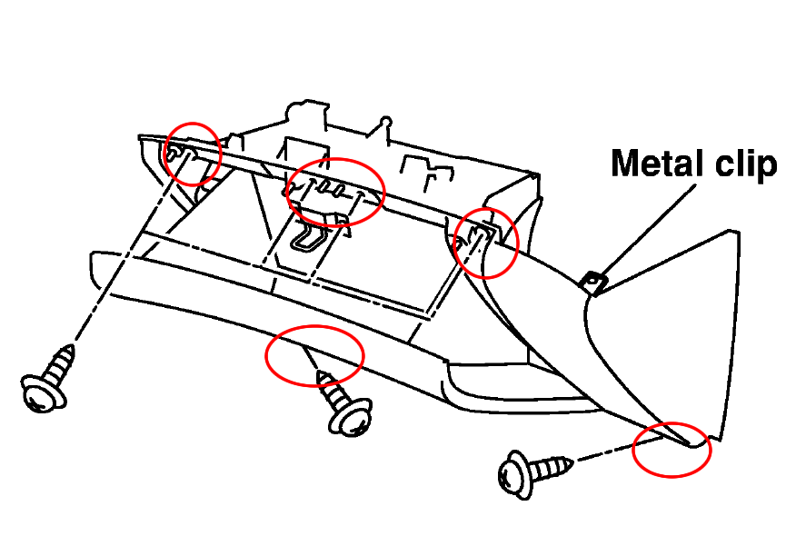
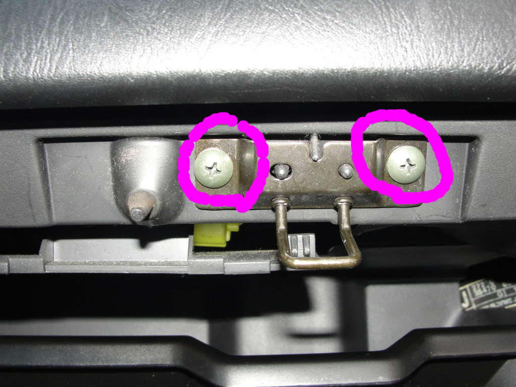
1. Remove the 2 glove box latch screws.

2. Remove the 4 screws holding the the glove box, two at the top and two at the bottom

3. Once the screws are removed pull out the glove box. You may need to use a crew driver to undo the right/top clip.

4. With the glove box removed, you will be able to see the “Fan Control Amplifier” for automatic air condition system or “Blower Motor Resistor” for the manual system.

5. Remove the 2 screws holding the Amplifier/Resistor, pull out the Amplifier/Resistor and install the new one.

Loading

Community Member Credit: maximaboy12

Hey Guys so my blower would make a lil rubbing noise so I went under there and cleaned it out. And might as well make a write up for all the n00bies out there. I saw a lot of pics for the 4th gen but not 5th so might as well do this.

1. Go ahead and open the glove box and start removing these bolts.

Name: DSC07198.jpg Views: 404 Size: 63.6 KB

Name: DSC07199.jpg Views: 338 Size: 67.3 KB

Name: DSC07200.jpg Views: 298 Size: 179.1 KB

2. These bolts are in the foot well.

Name: DSC07203.jpg Views: 244 Size: 116.7 KB

The next screw is under this panel. Go ahead and remove the plastic nut (pictured)

Name: DSC07213.jpg Views: 294 Size: 243.8 KB

Name: DSC07215.jpg Views: 288 Size: 239.6 KB

3. Now just give a gentle pull and the glove box should give way you will see two harnesses. Remove them. One is the light. It would be smarter to just move the clips on the yellow one. DONT UNPLUG THE YELLOW HARNESS THAT IS YOUR AIRBAG.

Name: DSC07202.jpg Views: 287 Size: 152.8 KB

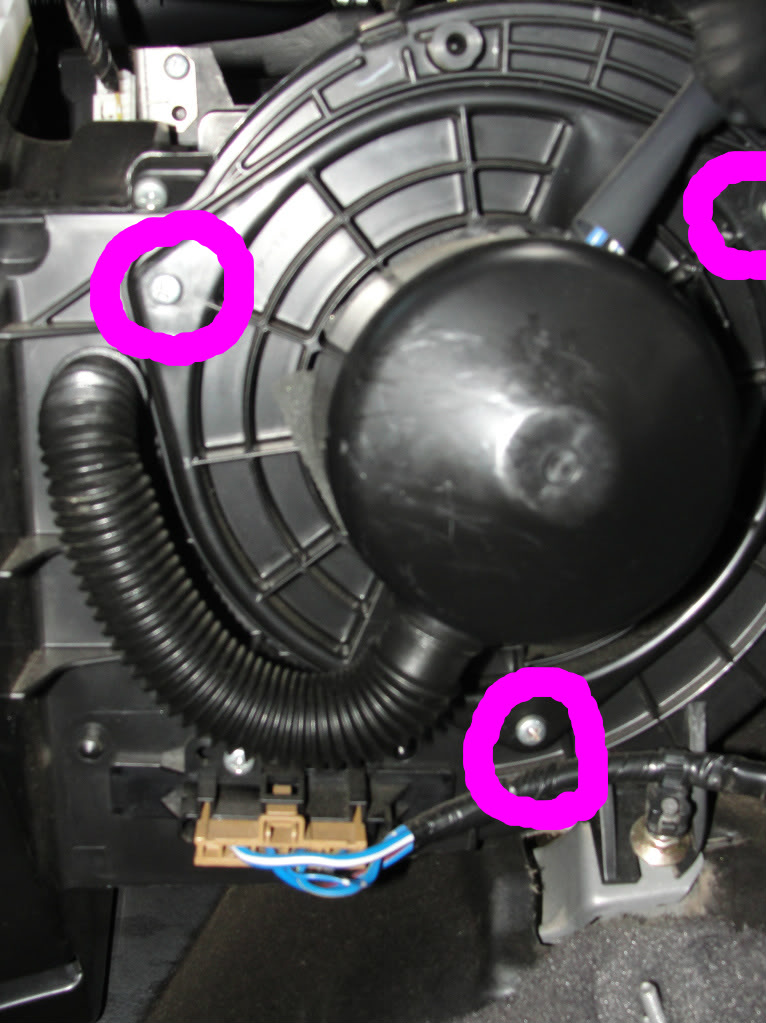
4. Now if youre looking for the blower heres what screws to remove.

Name: DSC07209.jpg Views: 314 Size: 142.6 KB

5. For the cabin air filter just remove the clip.

Name: DSC07210.jpg Views: 324 Size: 54.6 KB

I hope this helps all you guys! Good luck with all your mods fixes and everything. INSTALLATION IS REVERSAL OF REMOVAL GOOD LUCK GUYS

Reference Video:

Loading

Community Member Credit: Sparky

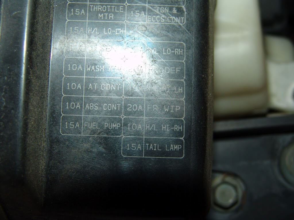
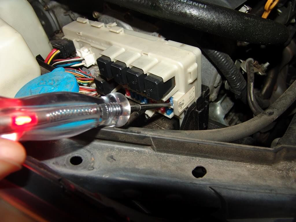
This 2005 Nissan Maxima came in with the complaint that the tail lights do not work and the fuse blows. The tail light fuse is located in the underhood fuse box on the passenger side of the vehicle. The black plastic trim panel that runs from the firewall to the headlight assembly has to be removed. There are several push pin retainers that hold it in place.

With the trim panel removed grab the fuse box cover and pull it up and off of the fuse box. Note the position of the tail light fuse on the fuse box legend. Be careful around the fuse box and use a gentle hand. There is a processor built into the intelligent fuse box assembly.

Locate the fuse in the fuse box and test both sides of the fuse. This one had power on one leg but not on the other. I replaced the fuse and the park/tail lights started working again. Normal inspections of the bulbs and related wiring found nothing. I started bouncing the body around to see if the fuse would blow. Nothing. I started opening and closing the doors firmly and the fuse blew. Replaced the fuse again and the lights stayed on.

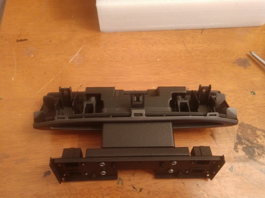
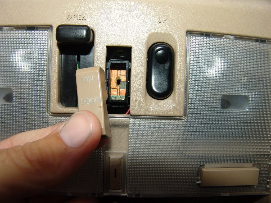
While sitting in the car contemplating what to check next, I noticed that the dome light switch in the overhead console was not sitting properly. A gentle wiggle and the fuse blew. I knew this because the dash illumination lights changed in intensity. A little more wiggling and the switch fell apart.

I found it strange that there would be a tail light circuit attached to the dome light switch and I could find no reference to this in the wiring diagrams.

Once the leading edge fasteners were free the two metal clips at the rear of the assembly were easy to remove.

The dome light switch unplugs from the back of the assembly. The switch and harness are then removed from the front of the light assembly. I called my Nissan dealership to find out that the switch is not sold separately. The cost of the assembly is $350 and only four in the country.

I did some testing and found that if I connected the white wire to the orange wire the dome light would work as if the switch was placed to the auto/door position.

A couple of snips. A splicing connector, some heat shrink tubing and the dome light works as most people expect anyway. Open the door and it comes on. Close the door and it turns off. Slight delay since it is a Nissan design. They prefer their dome lights to fade out gradually.

So if you have a hard to find short in the tail light circuit be sure to check this switch out. If you also do not want to spend $350 on a new light assembly but want the dome light to work, just connect the orange and white wires together as I did. I would strongly recommend checking the wire locations and electrical circuits yourself. Sometimes manufacturers will change the wire color codes for internal wiring and yours may or may not match this one.

The park lights now work without the fuse blowing and the dome light works as the customer requested.

Loading

Community Member Credit: Sparky

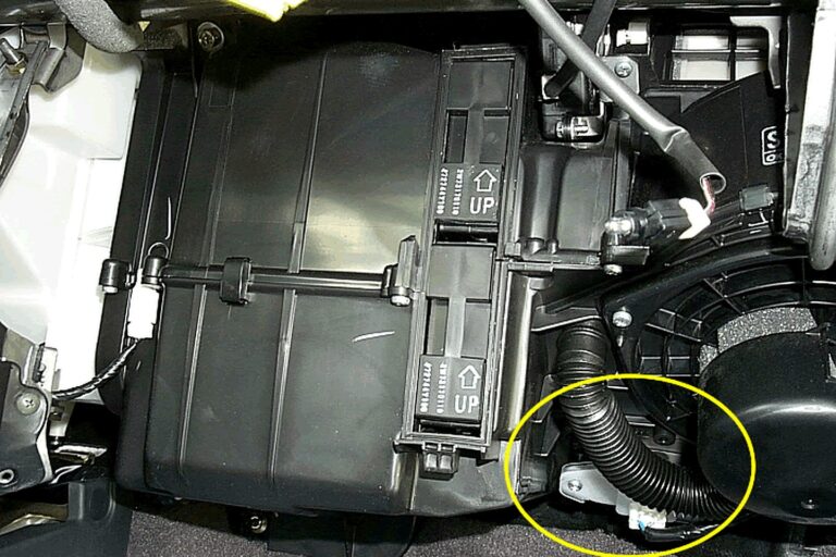
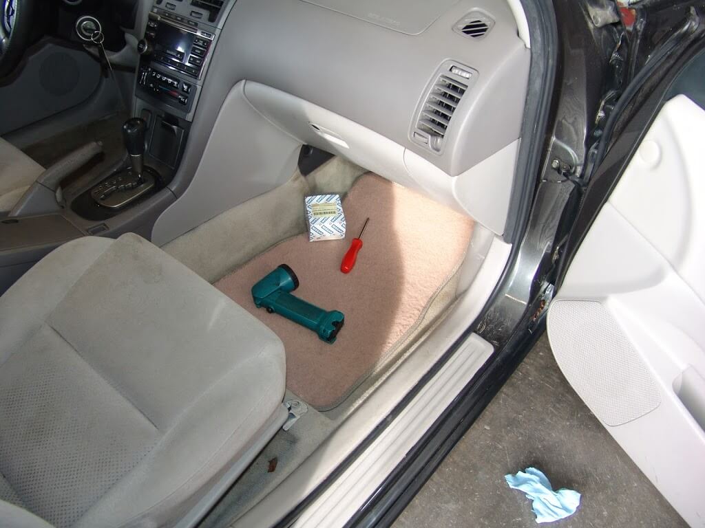
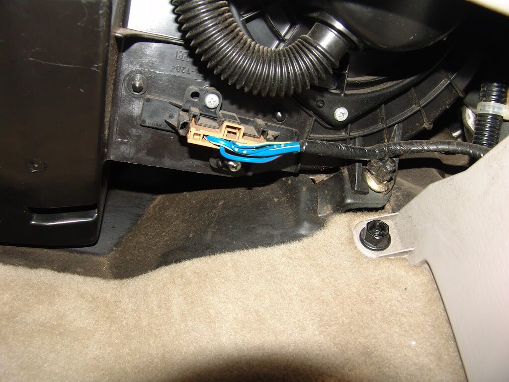
This 2003 Nissan Maxima came in with the complaint that only the highest blower speed was working. The air would not blow at all, on the lower speeds. Suspecting a faulty blower resistor, I went to the passenger side of the dash.

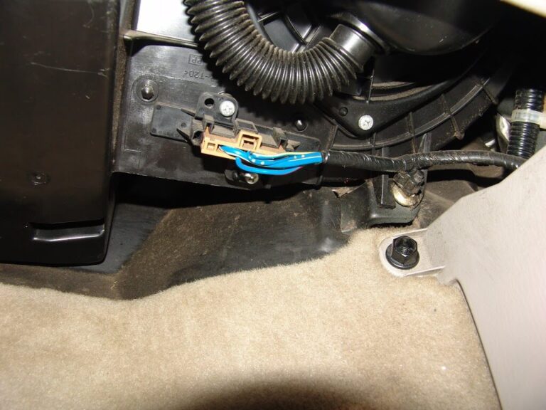
The blower resistor is located near the firewall under the passenger side of the dash. It is the piece that the connector with blue wires is attached to.

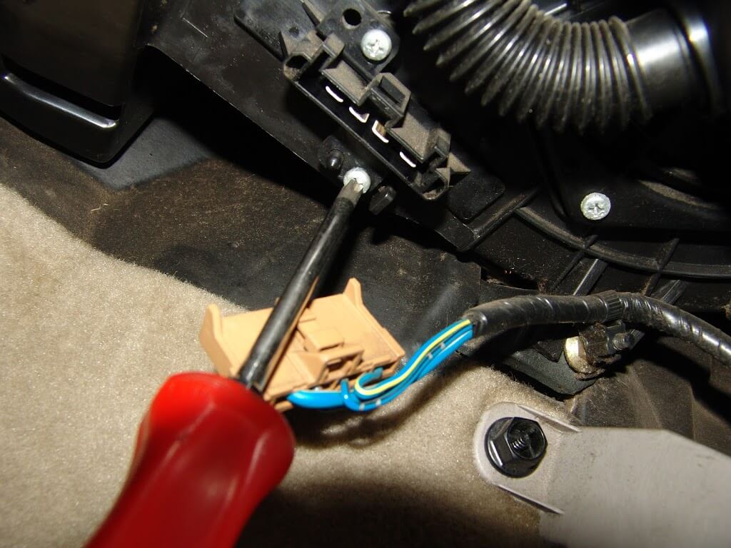
Two phillip’s headed screws hold the resistor to the blower housing.
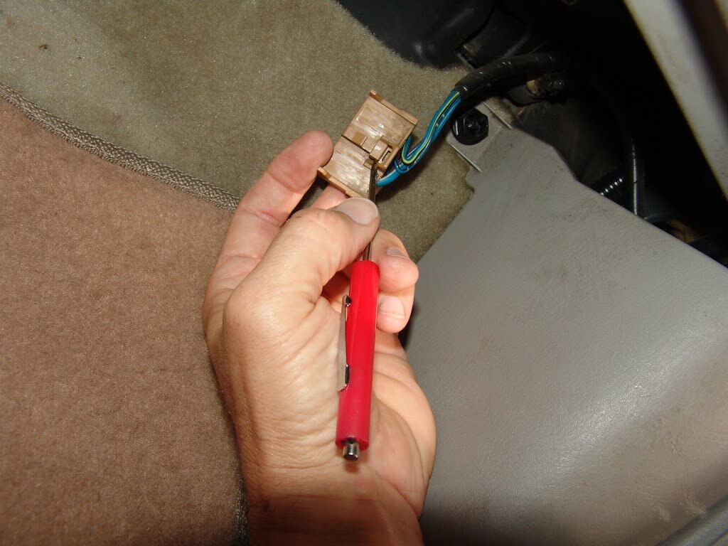
To release the locking tab, it needs to be pushed in where I am pointing at with my pocket screwdriver.

If you want to test the system this is what you will need to know.

The blower resistor and blower switch are on the ground side of the blower motor circuit.

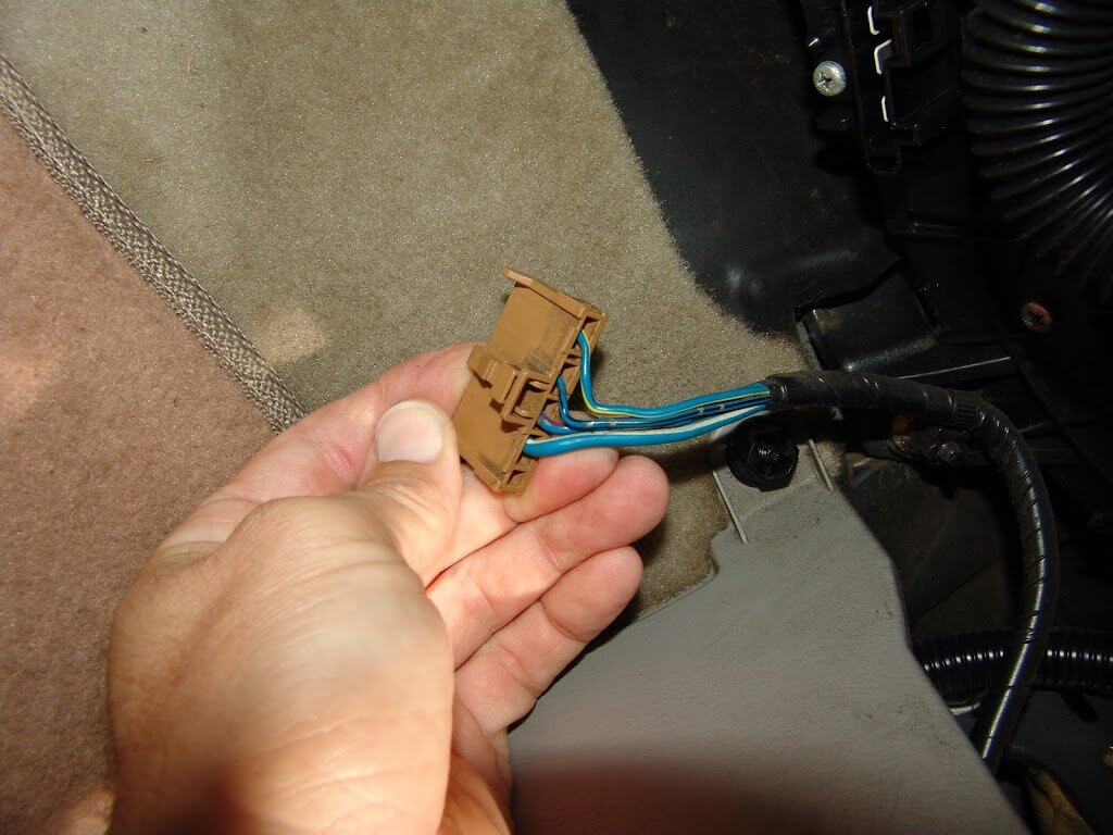
With the resistor harness disconnected and the ignition on, there will be bleed through battery voltage on the larger blue/white wire. In the blower switch position 4 or high the blower switch directly connects this wire to chassis ground and the highest blower speed is achieved.

When the blower speed is set to the 3 position the ground is sent from the blower switch to the resistor on the blue/red wire. It passes through one resistor and the speed is reduced slightly.

When blower speed 2 is selected the ground again is sent form the blower switch to the resistor but this time it is sent on the blue/yellow wire. At the resistor is passes through two resistors and the speed is dropped even further.

When blower speed 1 is selected the ground signal again is sent from the blower switch to the blower resistor and this time it is on the blue/black wire. At the resistor is passes through three resistors and the lowest blower speed is achieved.

If there is no bleed through voltage at the blue/white wire you will need to see if there is power on the white/blue wire at the blower motor itself.

If voltage is not present on the white/blue wire at the blower motor you will need to check the fuses and relay. If power is present the blower motor is faulty.

I also wound up checking and changing a restricted cabin air filter in this vehicle. It is likely that the dirty filter contributed to the resistor failure.

Loading