To give it a cleaner, more OEM-inspired look, I removed the chrome rings from the factory housing (the original ones had snapped at the ends). After some careful sanding and a bit of superglue magic, I smoothed everything flush and mounted the rings onto the new bezel.
Turned out awesome — much cleaner and way better than running without any chrome around the gauges!
Just wanted to share something that might interest fellow Altima SE-R owners. As most of you know, finding an OEM gauge bezel in good condition these days is nearly impossible. And even if you manage to track one down, it’s still a 20-year-old piece of plastic — super fragile and prone to cracking the moment you try to install it.
Well, I recently came across an aftermarket bezel from Sonic Electronix, and honestly, it’s impressive. The fit and finish look great, and the best part? It’s made from a much newer, sturdier plastic material. No more worrying about snapping tabs or cracking corners during installation.
The only thing I’ve always loved about the OEM version is those chrome rings around each gauge. This one doesn’t include them, but I’ve already got a plan to add that finishing touch myself. Once I’ve done the mod, I’ll post an update with photos and a quick walkthrough.
Member Credit: Hassan A. / Ethan G. Download PDF:link
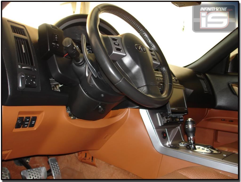
This guide covers the installation of an 8th-generation (2016–2020) Nissan Maxima steering wheel onto a 5th-generation (2002–2003) Maxima. The setup enables full button functionality and backlighting. The steering wheel is from a 2019 Maxima (with audio and cruise control buttons, non-adaptive cruise).
Assumptions:
You’re willing to relocate the drive computer button elsewhere.
You don’t require the drive computer display to function.
You have an aftermarket stereo with a working steering wheel control interface (e.g., PAC SWI-RC module).
Airbag Wiring
This is the custom harness for airbag connections using yellow connectors. This section focuses on splicing and matching the correct airbag plug types from the 8th-gen wheel to the 5th-gen airbag system.
Steering Side Wiring for Lights and Buttons
Button Resistance Mapping (8th Gen Wheel)
There are 5 unique resistance values for 10 functions, so the wiring must be combined into a single signal line by adding a 1 kΩ resistor to one wire when merging signal lines.
Connector Pinouts
5th Gen Connector (Vehicle side)
Pins 13–20 handle functions like Mode, Volume, Cruise, Drive Computer, and Horn.
8th Gen Connector (Steering wheel side)
Adds an extra pin for illumination (12 V for button lights).
Pin Mapping Table (5th → 8th Gen)
5th Gen Pin
Function
8th Gen Pin
Function
13
Empty
13
Cruise Control (White)
14
Mode / Track Up (Orange)
14
V+, V−, Tel End, Display (Yellow)
15
Volume Down / Track Down (Blue)
15
Source, Up, Dn, Tel, Enter (Green)
16
Button Common (Yellow)
16
Cruise Control (Brown)
17
Cruise Control (Green)
17
Common wire for buttons (Blue)
18
Cruise Control (White)
18
Horn (Grey)
19
Drive Computer (Purple)
19
Ground (Black)
20
Horn (Red)
20
Light 12V (Red)
The 8th gen clock spring supports all buttons and illumination.
Re-Pin Order for 5th Gen Connector (Table 2)
Pin
Wire
Notes
13
—
Empty
14
Black
Ground
15
Yellow + Green (1 kΩ resistor added)
Signal
16
Blue
Common ground
17
Brown
Cruise
18
White
Cruise
19
Red
Lights
20
Grey
Horn
Diagram #1
Shows re-pinning layout and resistor placement:
Add 1 kΩ resistor between green and yellow signal lines.
Swap black and green wires as shown.
Connect Red → 12 V lights, Grey → horn, Blue → common ground.
Column Side Clock Spring Connector Modifications
To integrate lighting and drive computer trigger, modify 3 wires at the column-side plug:
a) Cut the red wire, solder its connector side to ground, and tap the car-side red wire into Blue/Yellow. b) Cut Green/Red wire, and connect its connector side to switched 12 V+ (from the Red/Blue wire near driver kick panel, used by headlight switch). c) Column-side Green/Red wire is the Drive Computer trigger — wire it to an external momentary switch if you want to retain trip computer function. d) Identify the correct radio control wire on your stereo harness; follow your interface module programming guide. e) Reprogram your PAC SWI-RC or similar interface for new button functions.
Diagram #2
Shows:
Splice Red ↔ Blue/Yellow.
Connect Green/Red → 12 V switched (Red/Blue at driver kick panel).
Ground the cut Red wire’s connector side.
(Optional) Wire Drive Computer trigger to an external button.
Final Result
2019 Maxima steering wheel mounted in a 5th-gen dashboard.
All illumination LEDs and button functions (audio, cruise, phone) work properly.
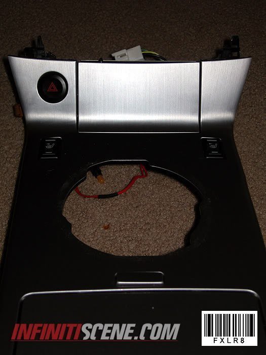
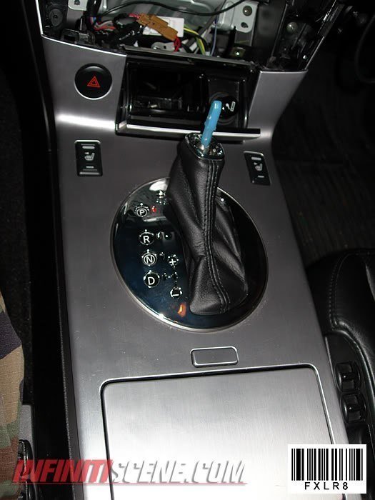
2. Remove old shifter panel top and bottom by unscrewing the screws on the underside of the old panel.
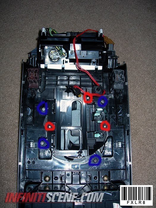
3. Put the new 2006 shifter panel and bottom boot together in the hole and screw the two pieces together with the 3 screws in red.
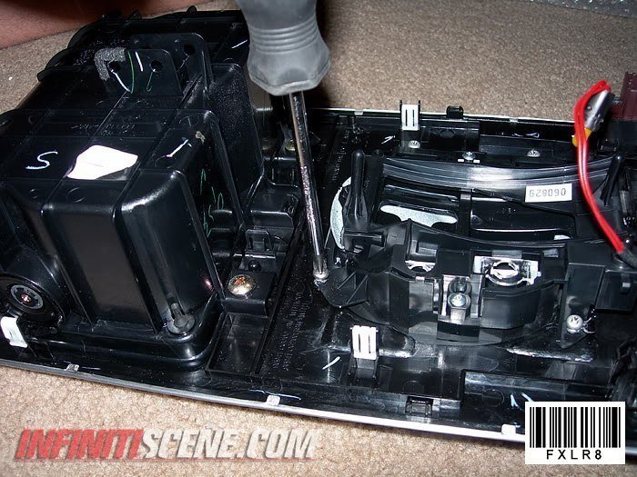
4. Now you are going to align the new shifter, on the two I did I pushed them all the way forward towards the front of the car and then centered it left and right.
Align the panel in a way where you can shift through all gears smoothly…..and then do the next step.
5. You then are going to figure a way to keep it from sliding around while you shift. I used 4 screws on each of the tabs shown in blue…you can use double-sided tape but I am not sure how well that will work while trying to align the piece.
REMEMBER: Do not screw the screw all the way in or you might go through the metal on the other side.
(MAKE SURE YOU ATTACH THE LIGHT UNDER THE SHIFT PANEL)
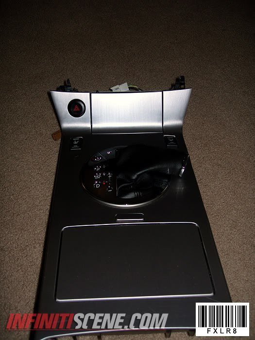
6. Put the completed panel and console back on the car, what I did was reattached all the wires…. make sure all items on the console work (lights, hazard signal, seat warmers, etc.). I then put the shifter in neutral and then slid the console on the shifter making sure I go through the shift indicator slider on the shifter panel.
7. Put your shift knob back on and make sure you can shift through all gears… after that put all your console pieces back together and your done!!
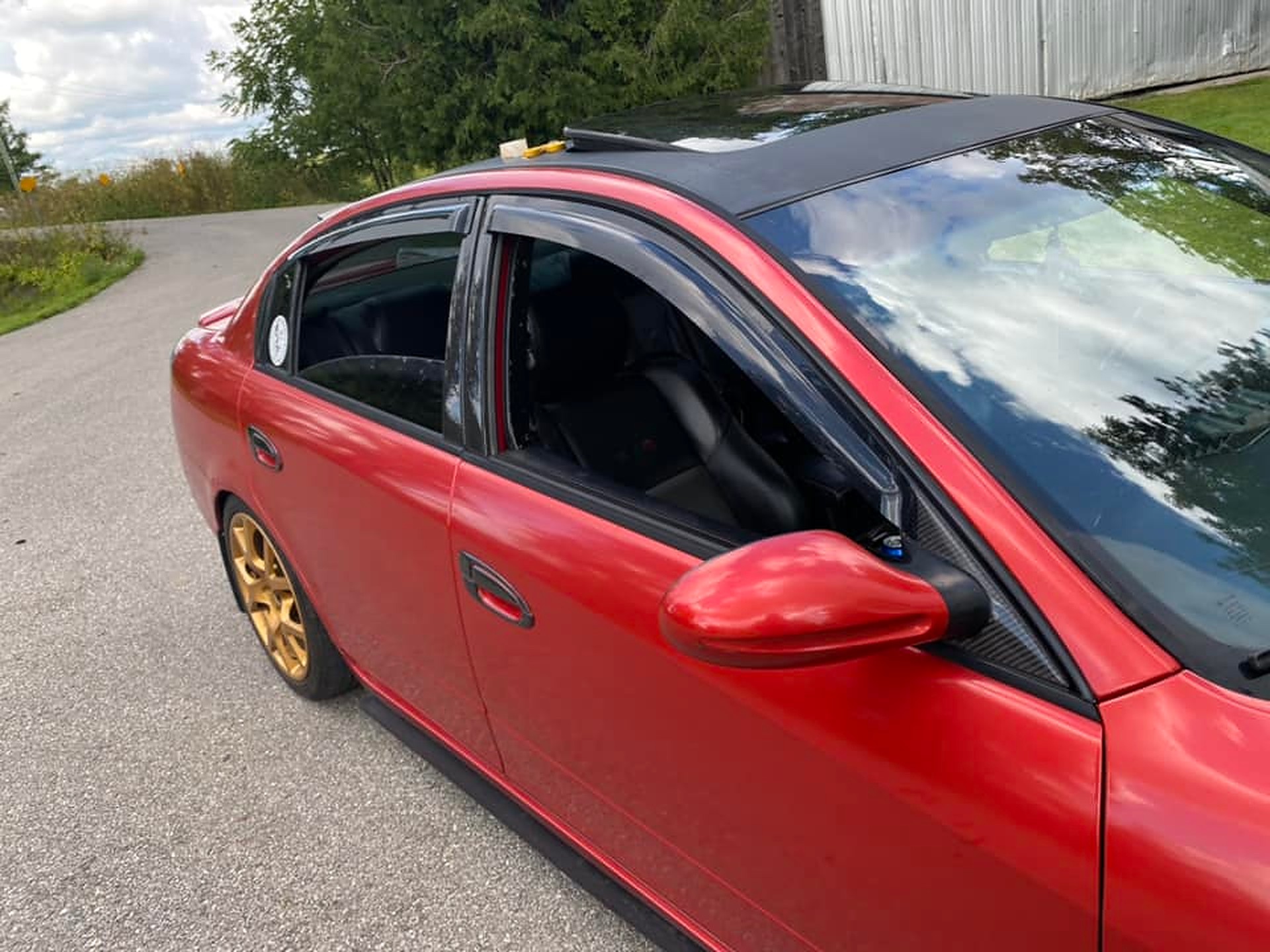
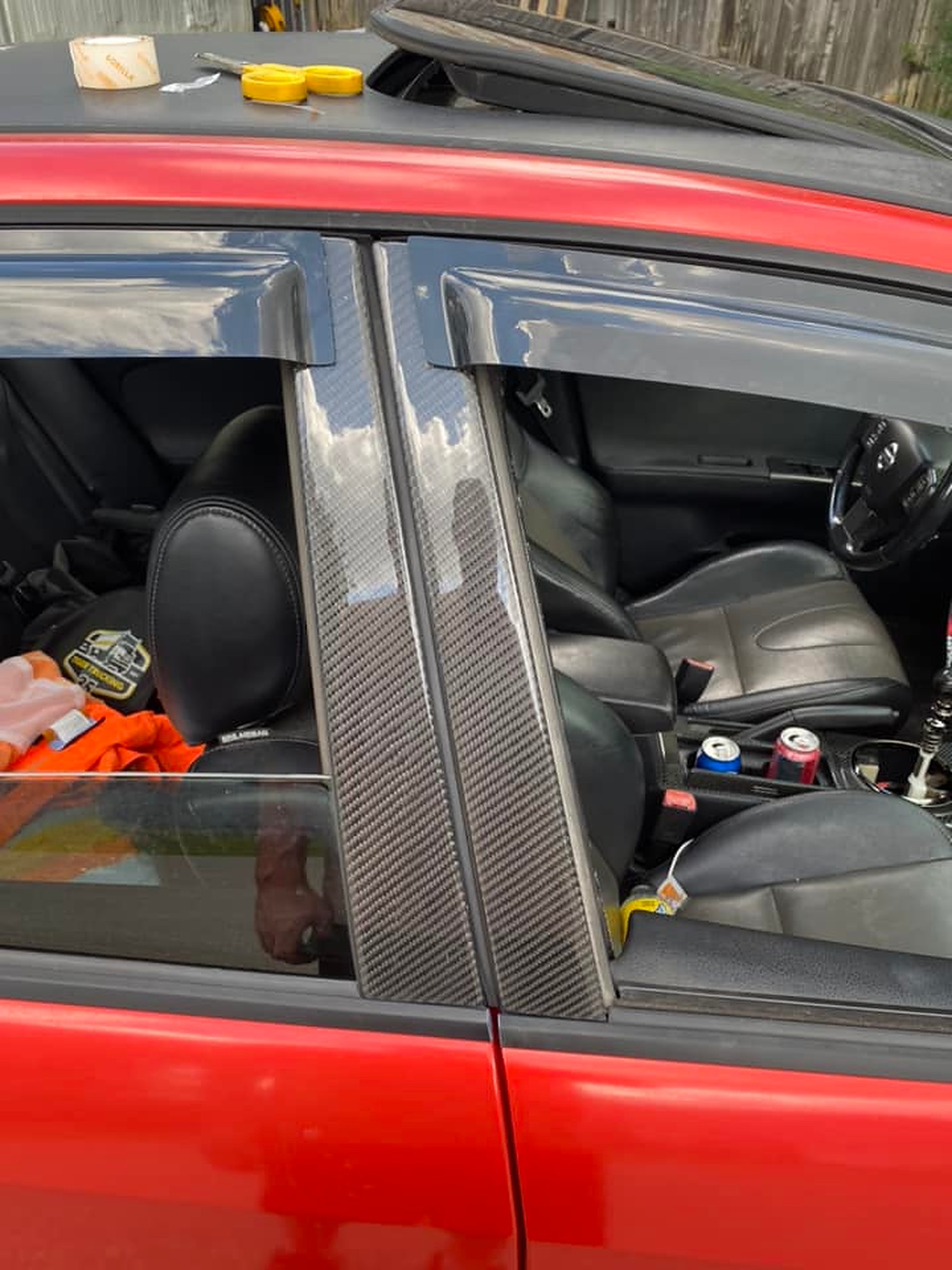
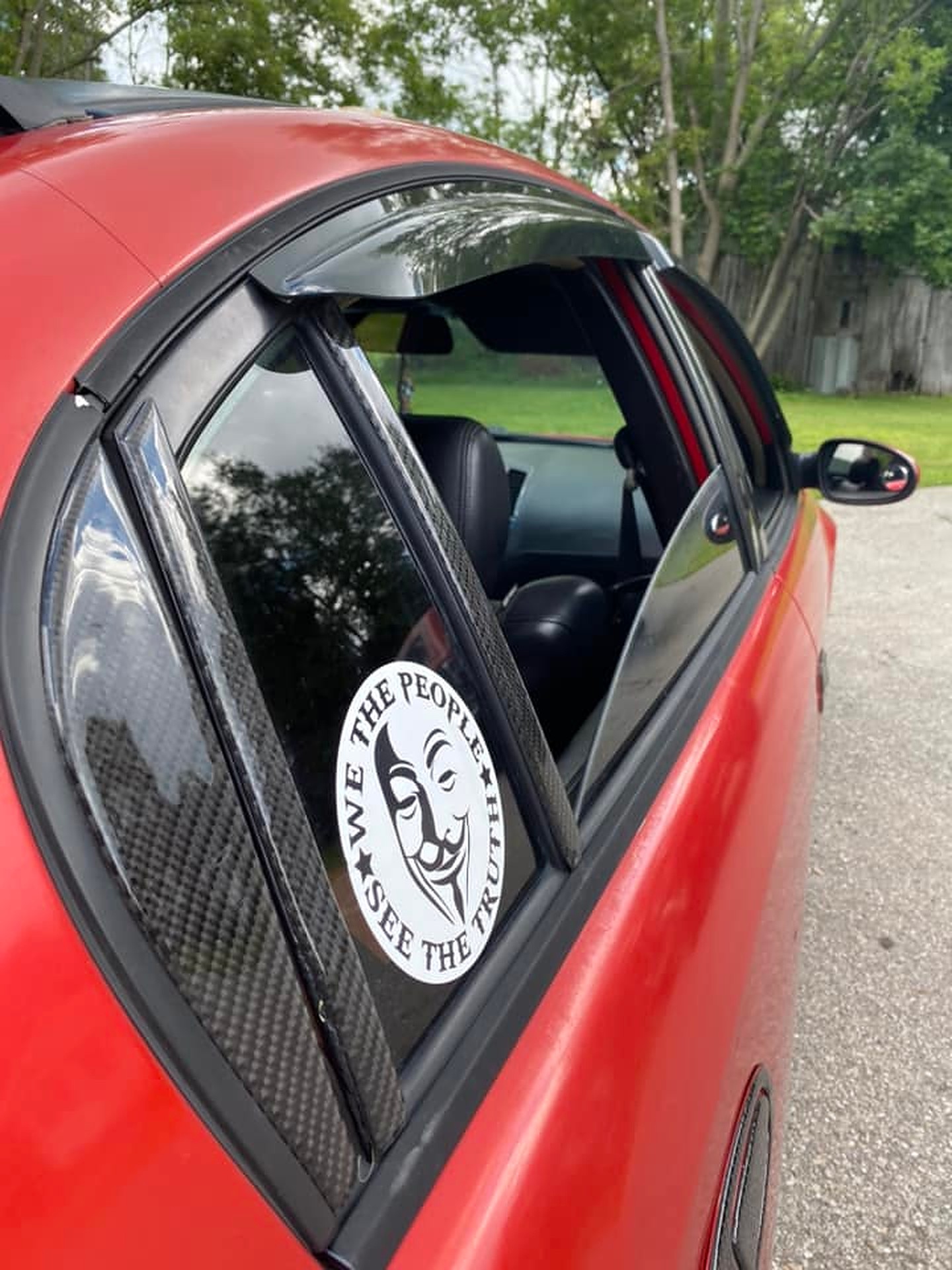
I recently spent $500 on some car parts/wraps and I have to admit, I’m pretty disappointed. From a distance, they might look okay, but up close, they don’t live up to the expectation. For starters, these parts don’t fully cover the trim. About 1/2” of grey trim is still visible on the doors. The ring around the shifter doesn’t fit well, and the stereo bezel needed to be cut to fit. While there’s a ring for the rear cupholders, I couldn’t find one for the front.
The door handle stickers, especially in any color other than black, make the whole thing look tacky. When applied, there’s a jarring difference between the sticker and the paint behind it, making it seem very unprofessional. These parts also feel quite thick to the touch, which adds to the tackiness.
Installation is another headache. If you don’t line them up perfectly, they jam. I’m particularly worried about the door handles and gas door – if I mess up their placement, it’s going to be a nightmare getting them off or even repositioning them.
To be honest, thinking about the cost, I believe I could’ve bought enough wrap to cover my entire car for the same amount. I don’t mean to be overly negative, but I just wanted to give my honest feedback.
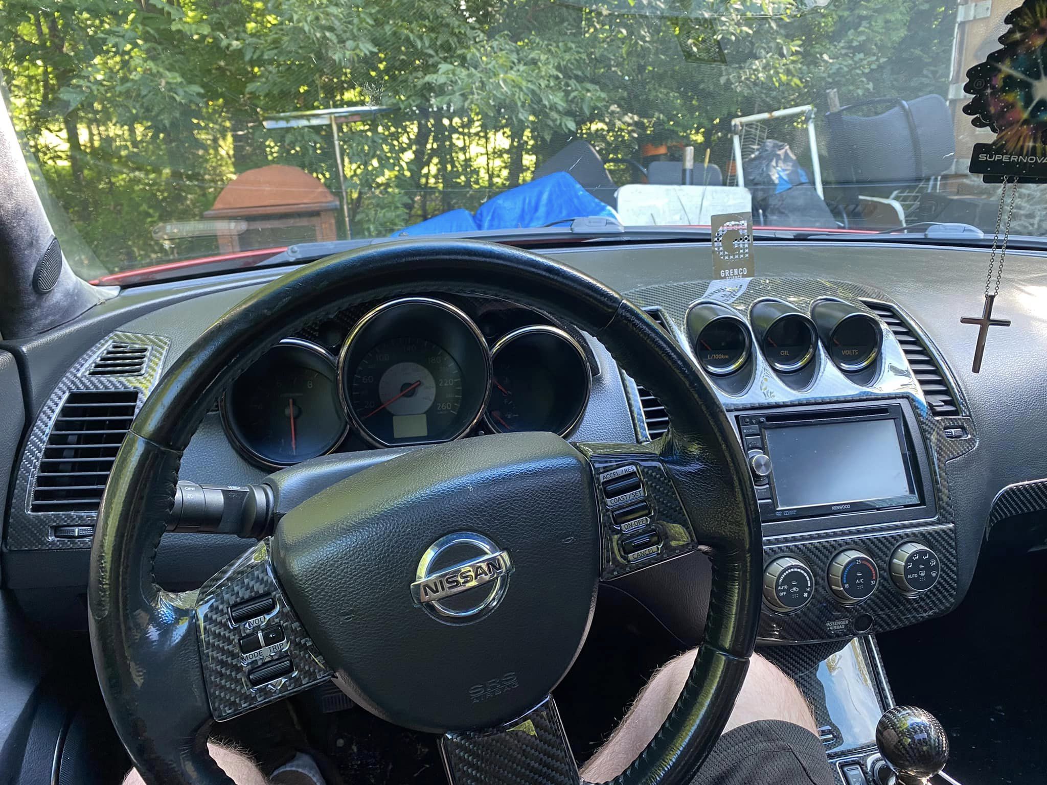
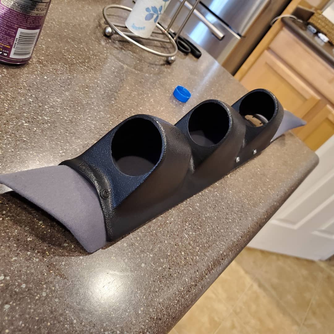
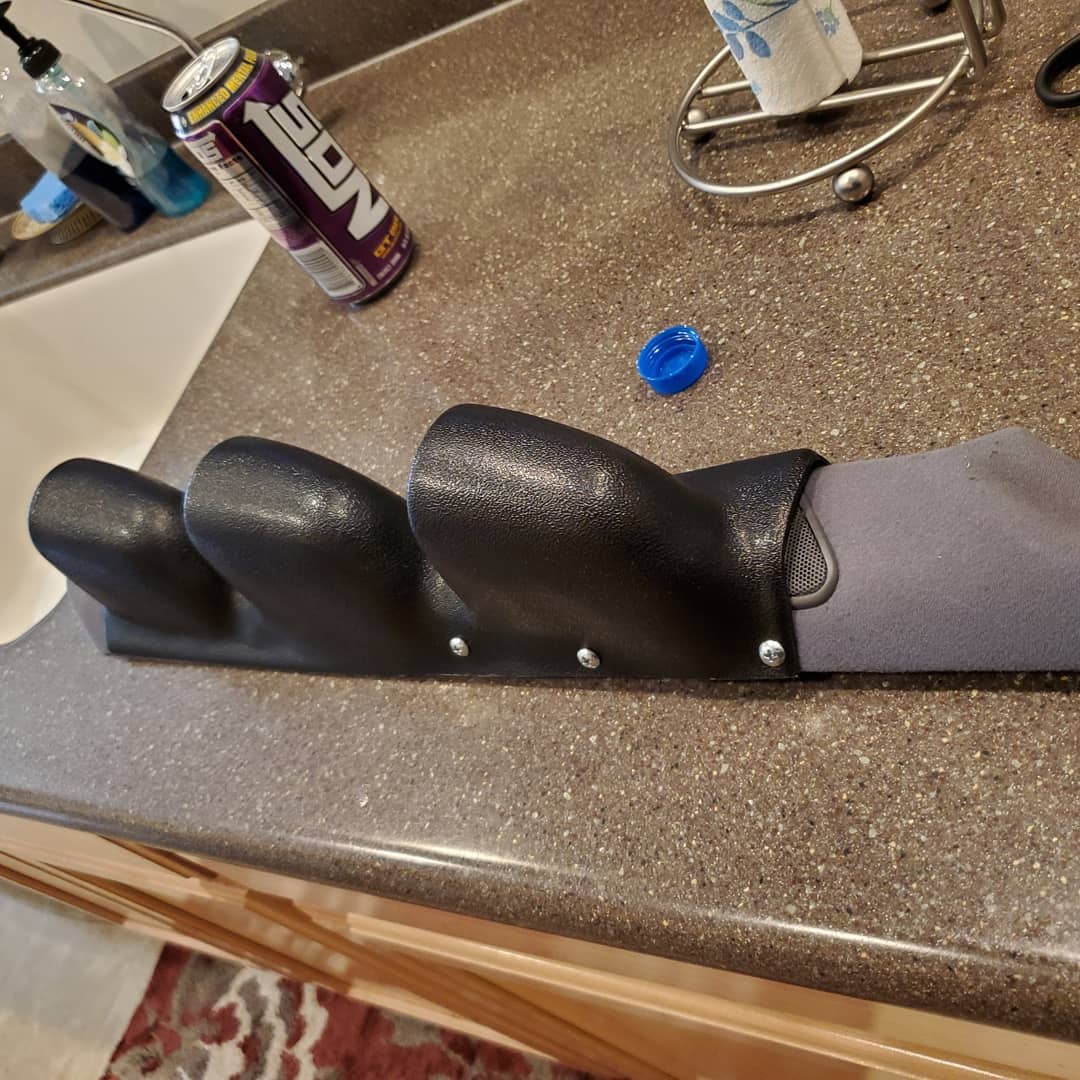
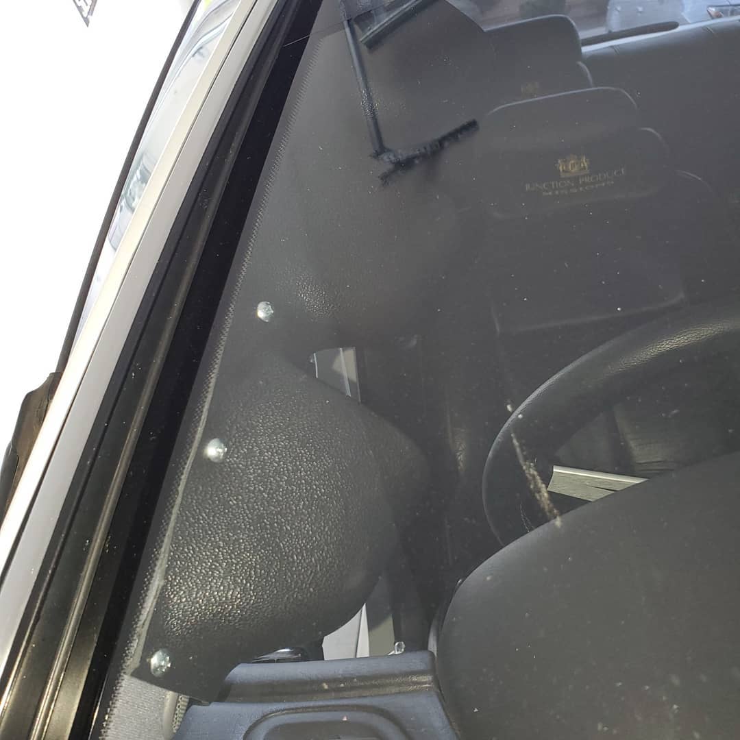
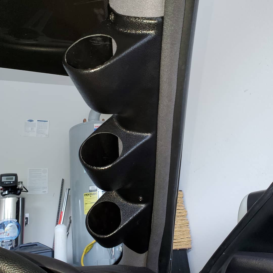
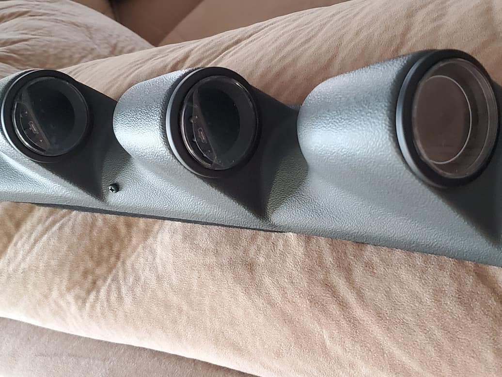
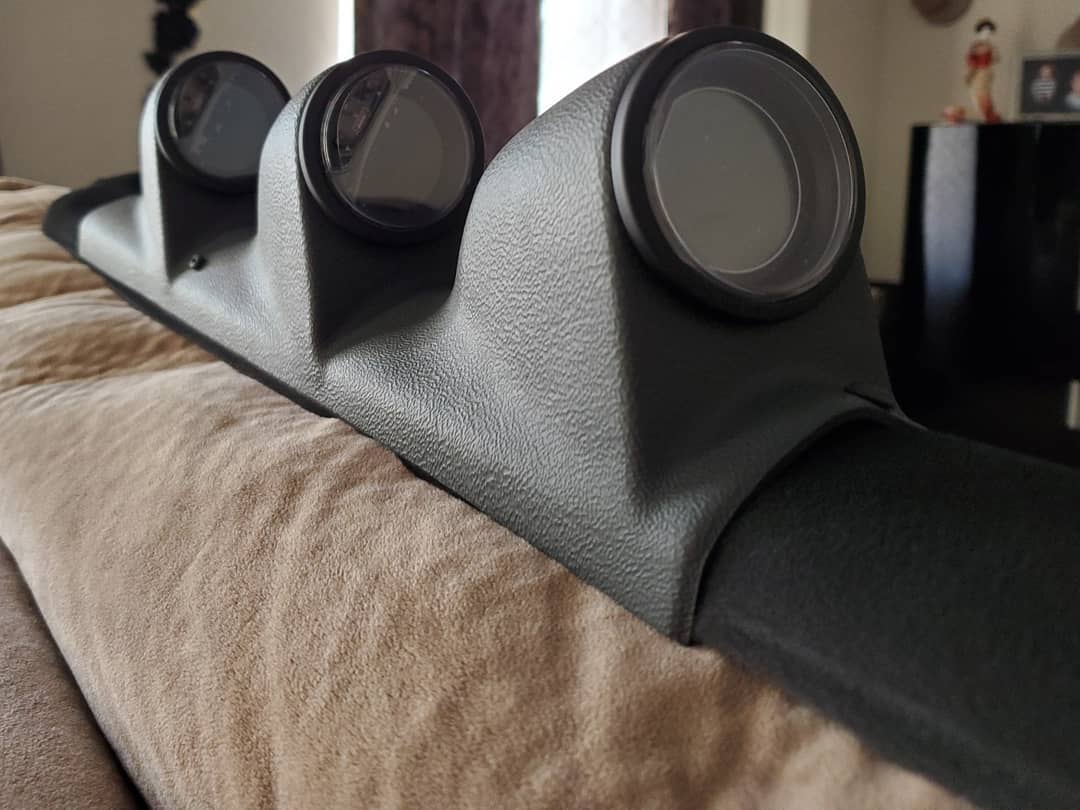
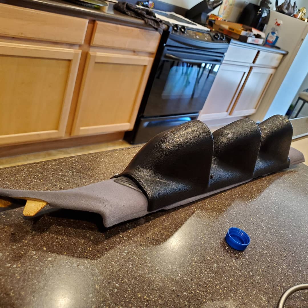
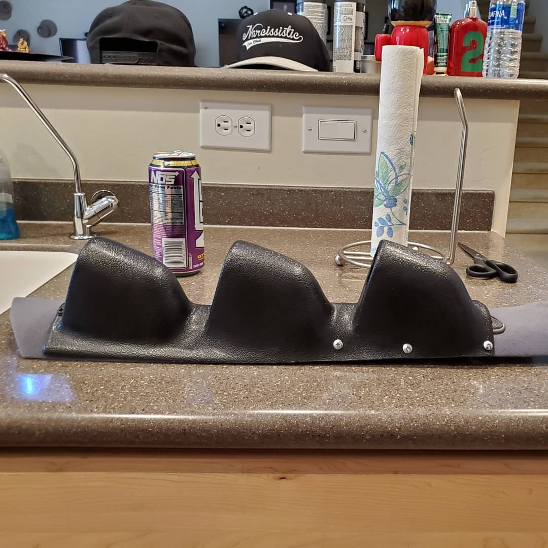
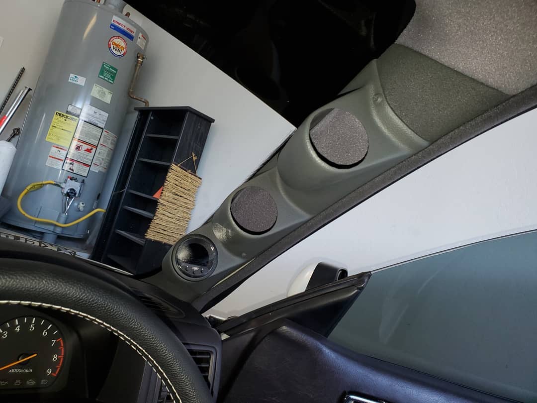
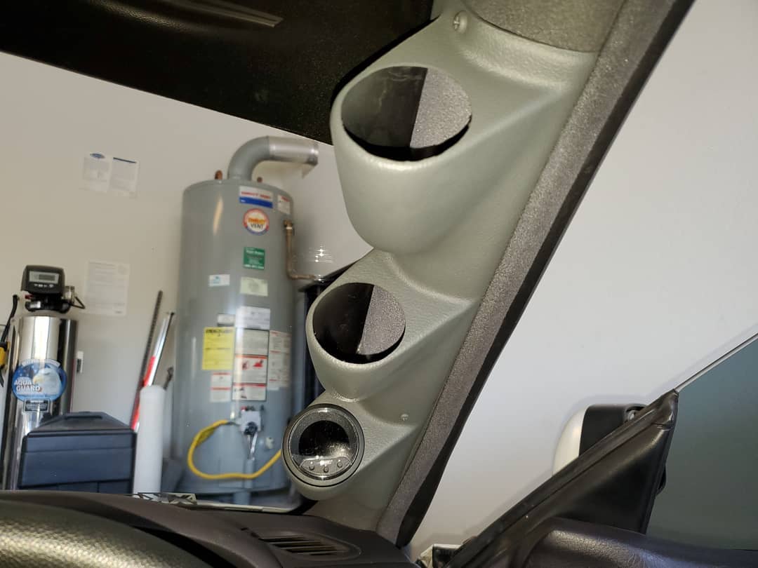
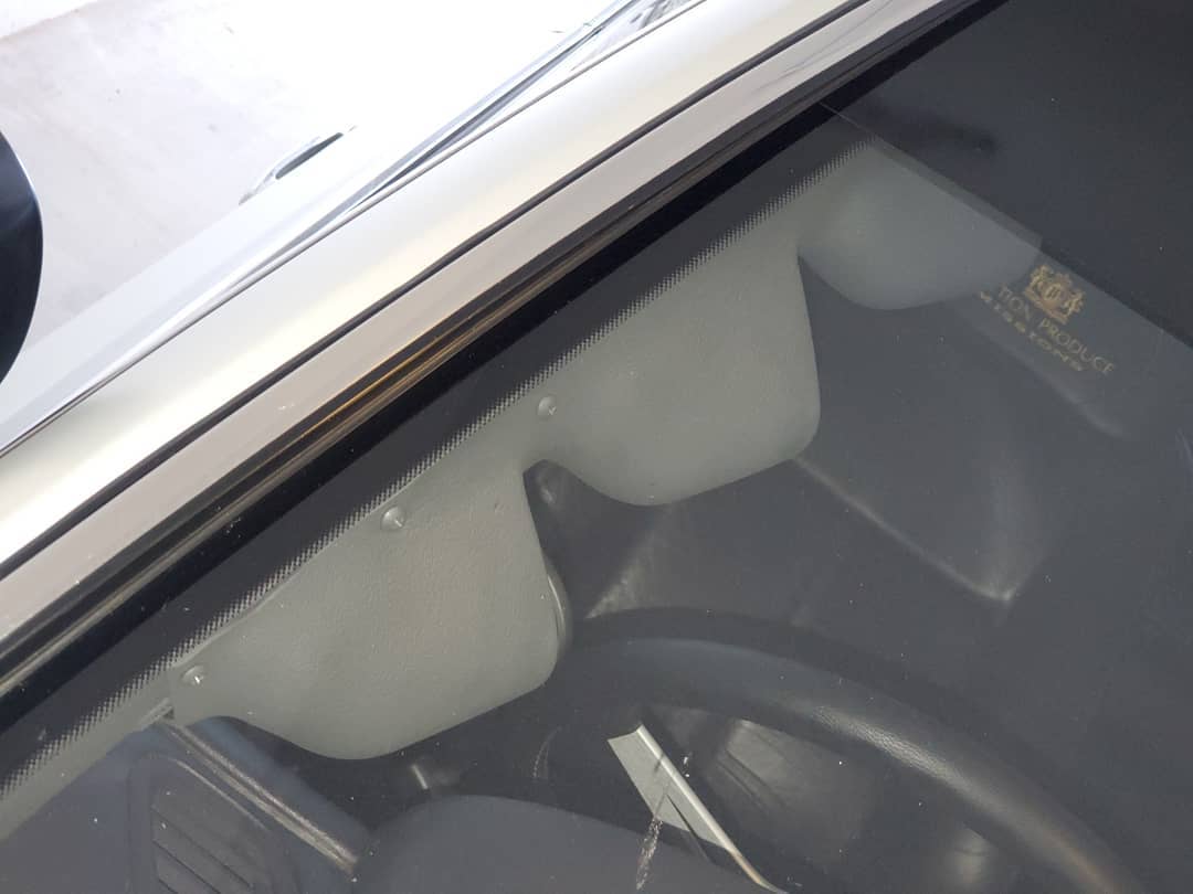
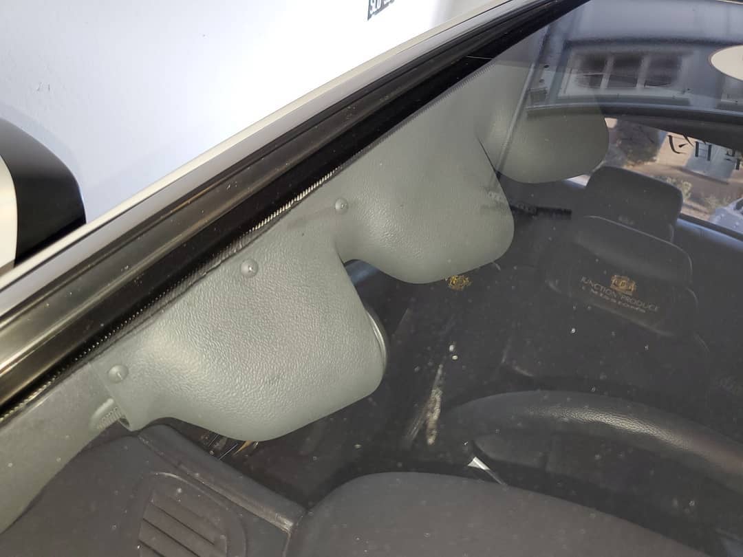
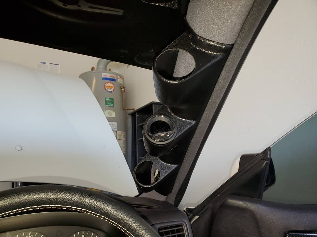
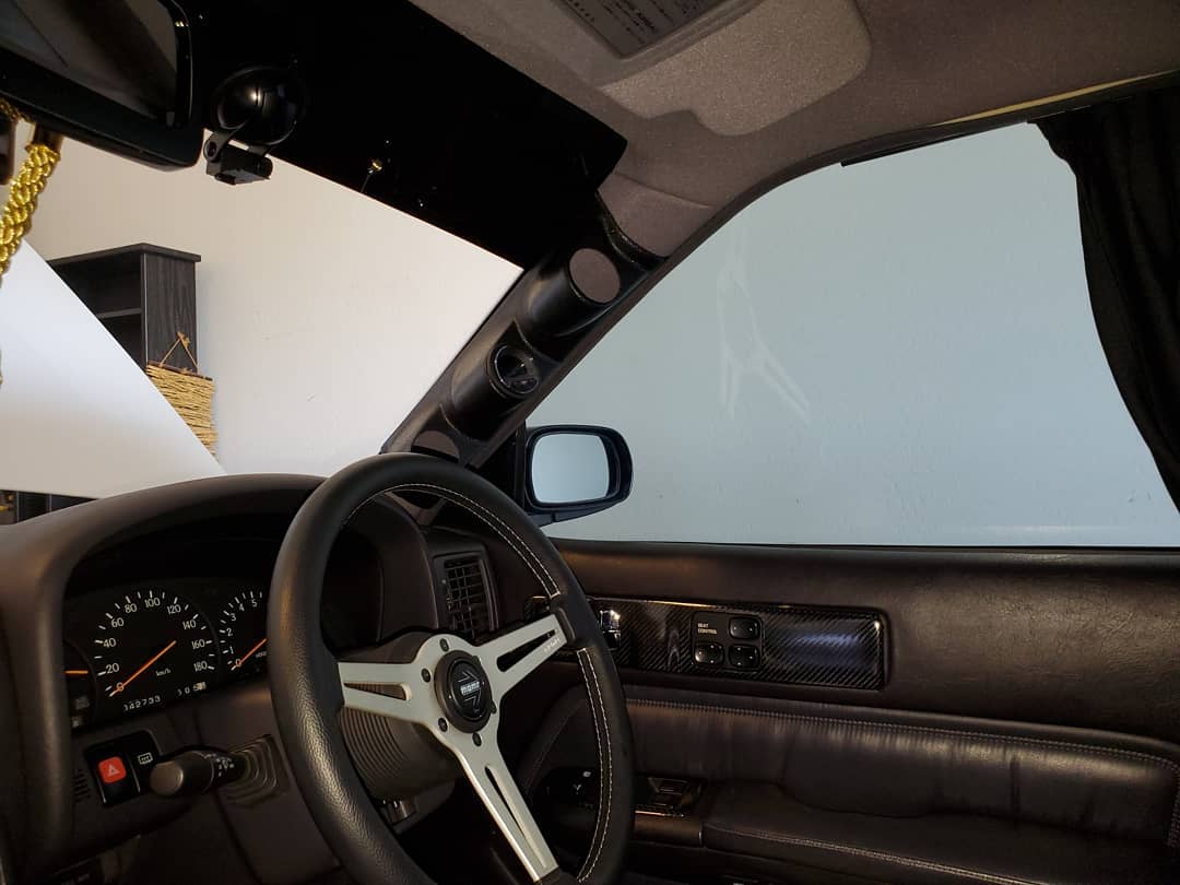
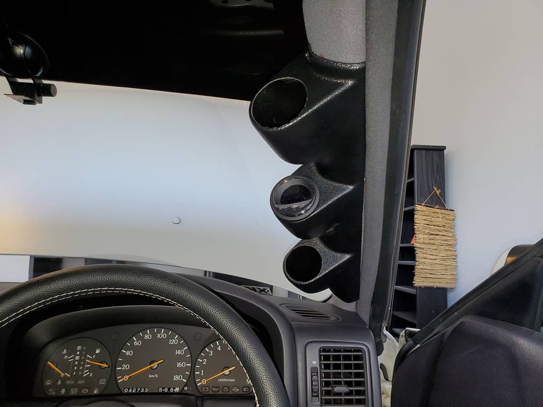
Testing the fit of the universal RHD @glowshift triple gauge pod with the Prosport Gauges Evo Series gauge/boost controller, paired with @kaizen_y32 sensors for oil temperature and pressure, voltage, boost, wideband, water temperature, and fuel pressure.
I would like to start by thanking JNCoRacer for his motivational pep talk. He was smart enough to know that I could do it, even though I didn’t think I could. Thanks man.
You will need various standard tools: screwdrivers (Phillips for screws & flat for prying), wire cutters and a ratchet, extensions (I found that my 24 inch was very useful), a U-joint, and a 10 & 12mm socket. I strongly recommend a 6 point socket for the 12mm.
You will need one special tool, a T50 Torx, 6 point security wrench. I didn’t have a security Torx but got lucky and was able to modify my standard T50.
Cliff notes version –
1 – Remove the glove box.
2 – Remove the radio/heater control cluster.
3 – Remove the speedometer cluster.
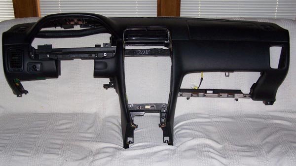
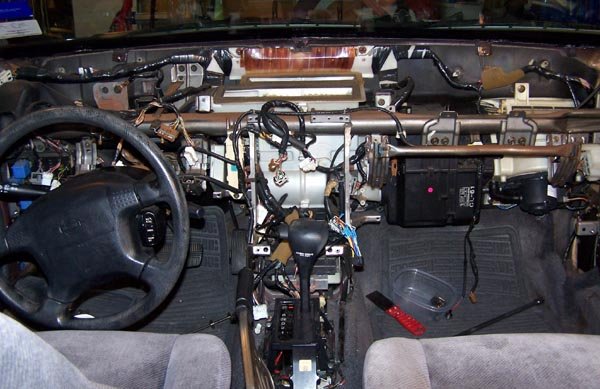
4 – Remove the dash.
Easy smeezy, right?
Let’s get started and find out.
Move the driver’s & passenger’s seats forward and remove the 2 screws that hold down the rear of the center console.
Move the driver’s & passenger’s seats all the way back.
Disconnect the battery. You will be messing with the passenger airbag and it is recommended to wait a half hour after disconnecting the battery.
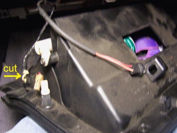
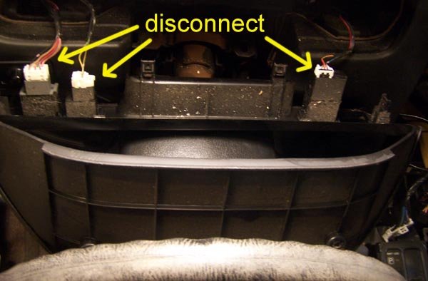
Remove the glove box (6 Phillips head screws) and disconnect the 2 wires. You will also have to cut the zip tie that holds the wire harness to the glove box.
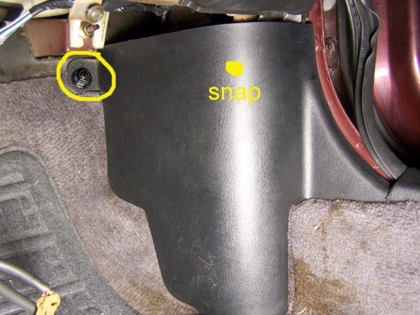
While you’re down here, remove the kick panel in the foot well. There is a plastic nut on the top front corner that you can most likely remove by hand. Then there is a snap along the top edge just before the panel curves to meet the door. Pull the panel towards the driver’s side to unsnap it.
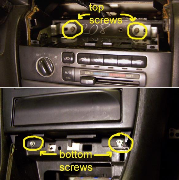
Remove the radio and heater controls. Start by removing the trim plate around the transmission shift lever. If you have an auto trans, you need to move the shift lever out of park. I’m guessing that you’ll need to do the same with a standard trans. Pry up the 2 rear corners of the trim plate to pop the snaps free. Actually, pry on the sides by the corners, not the bottom edge. Lift up by hand to pop the forward snaps that are near the curve. When free, disconnect the wire for the cigarette lighter.
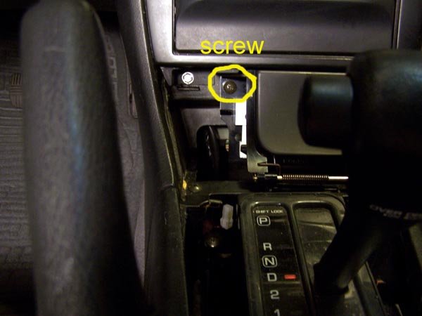
Remove the ash tray. Remove one screw at the top left corner. On the right side there are 2 snaps, one top and one bottom. Pry the ash tray straight back towards the rear. Did I mention that a 1 inch putty knife works better than a screwdriver for this? Disconnect the wire to the ash tray.
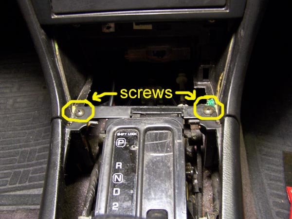
Now finish removing the center console. In the opening created by removing the ash tray, there are 2 screws in the corners where the center console meets the dash. Remove those screws, pull the parking brake handle up as far as you can, unsnap the boot around the parking brake handle and remove the center console by lifting up.
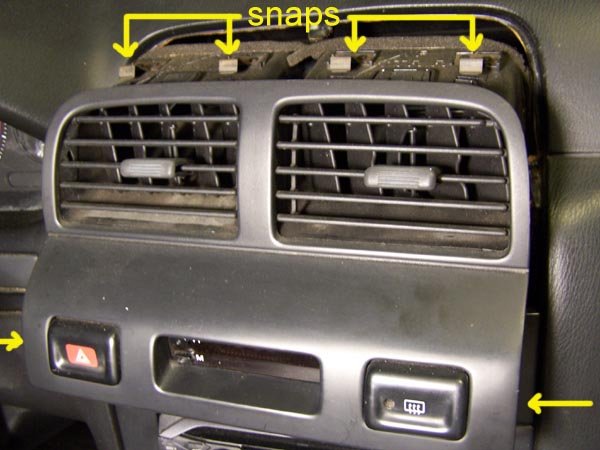
Remove the dash center vents. Pry up on the lower corners, the sides, not the bottom edge and pop the snaps free. There are 4 snaps across the top edge. Using moderate level swear words, free the top edge. While it is difficult to do, the vents need to come almost straight back with a little downward motion, not tilted up from the bottom. Once you have the vents free, disconnect the wires for the hazard flasher, clock and the rear window defroster switches.
Now you can remove the radio and heater controls. This is one unit held in by 4 screws, one in each corner, 2 screws down where the ashtray was and 2 on top above the heater controls. Have your transmission shift lever towards the rear of the car and lift out the radio/heater controls. Disconnect the wires from the radio and heater controls.
Remove the speedometer cluster. Since the goal is to remove the dash, this procedure will do things not needed if all you wanted to do is remove the speedometer cluster.
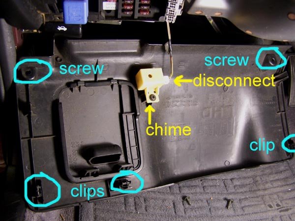
Start by dropping the steering column. Remove the lower dash trim panel that runs underneath the steering column. Remove the 2 screws in the bottom edge at the corners. There are 2 snaps on top edge, again at the corners. Pry the snaps free. *** Caution *** The chime that sounds when you open the door when you have the keys in the ignition is attached to the backside of this panel by the fuse panel. Disconnect this wire.
While you’re down here, remove the kick panel in the foot well, just like on the passenger side.
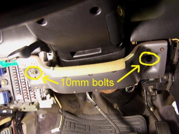
Remove the metal plate that runs underneath the steering column. There is a 10mm bolt on each end. The plate will stay in place after you remove the bolts. Slide the plate towards you about a quarter inch and it’s off.
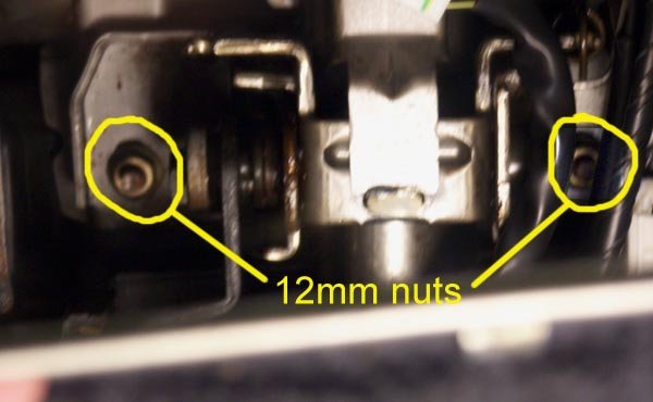
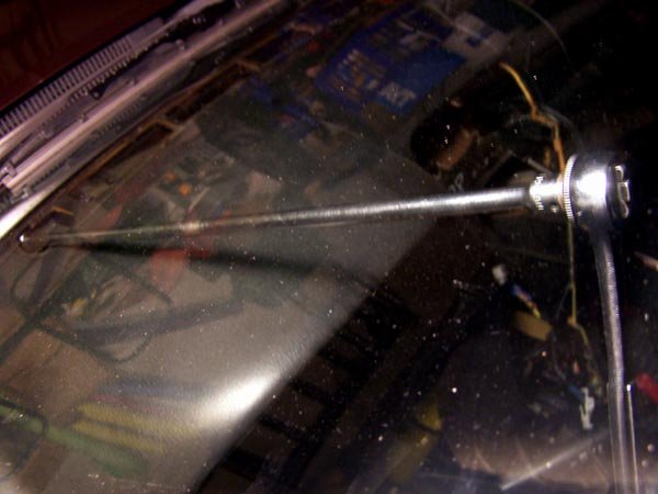
Now you can drop the steering column. Two 12mm nuts. Mine had Locktite on them and my 12 point socket was starting to strip the one nut, so I changed to a 6 point socket. The steering column is kind of heavy, so you are forewarned. I was concerned about the steering column hanging by itself, so I found a 10 inch length of 2 inch PVC pipe that I rested the steering wheel on.
Now for the speedometer cluster. There is a finishing bezel around the cluster that also has the cruise control on/off switch, the security led and the dash light dimmer switch. You have to disconnect the wires from these switches. You have 2 choices – before you remove the bezel or after. If you choose before, then you have to pry the switches out of their holes and then disconnect the wires. I chose the other option, after I had the bezel loose. This way I didn’t have to pop the switches out.
Start removing the bezel by removing 2 screws in the top curve of the bezel. Then there are 4 snaps along the bottom edge. Pry/pull them free. If you hadn’t done so earlier, disconnect the wires from the switches.
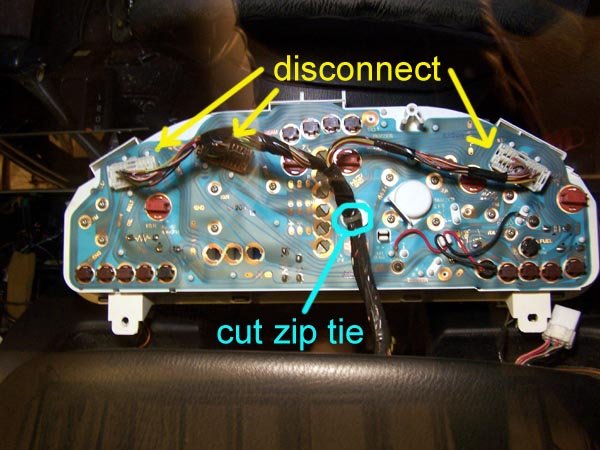
Finally, the speedometer cluster itself. 3 screws, 1 at the top and 2 along the bottom. There are 3 connectors on the back of the speedometer cluster that need to be disconnected. I would suggest you get something soft to lay the cluster face down on while you disconnect the wires so you don’t scratch the face plastic. It costs about $35. You will also have to cut a zip tie that holds the wire harness onto the back of the cluster.
Now disconnect the wires from the side view mirror switch. Either pop the switch out or reach in from behind the dash.
The final phase, remove the dash. There are 5 10mm nuts, 2 Torx head security bolts and a pair of screws to go.
Remove the trim pieces from the windshield pillars by grabbing the trim at the top edge and pulling the snap free. Then lift it off.
Pry off the defroster vent grill plates. There are 4 snaps spaced along the back edge. Pry the back edge of the grill up.
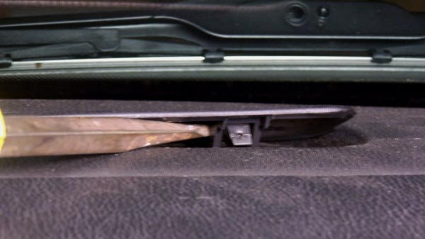
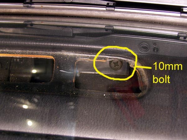
When the grill is removed, you can see a 10mm bolt at the end closest to the outside of the car. Remove this bolt. This is where my 24 inch extension was useful.
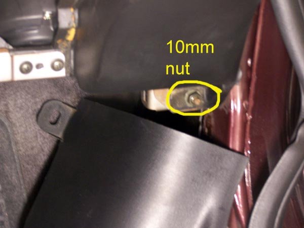
In the bottom left and right corners of the dash is a 10mm nut that was revealed when you removed the kick panels. Remove these 2 nuts.
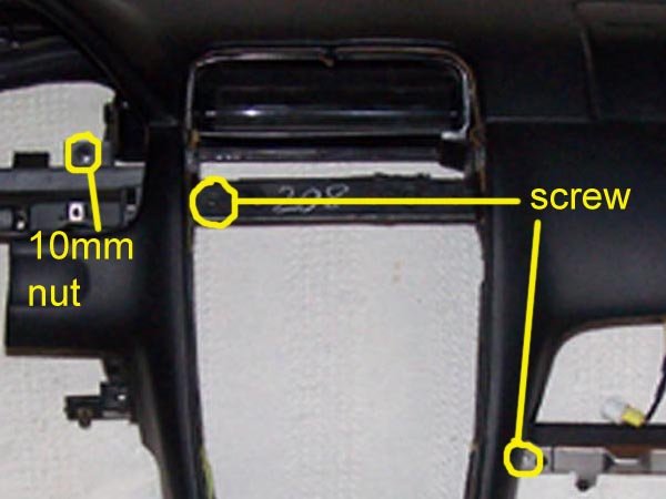
In the opening where the speedometer is a 10mm nut.
In the opening where the radio was there is a screw.
In the opening where the glove box was is a screw.
OK, last 2 fasteners and one wire harness connector.
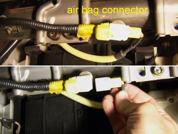
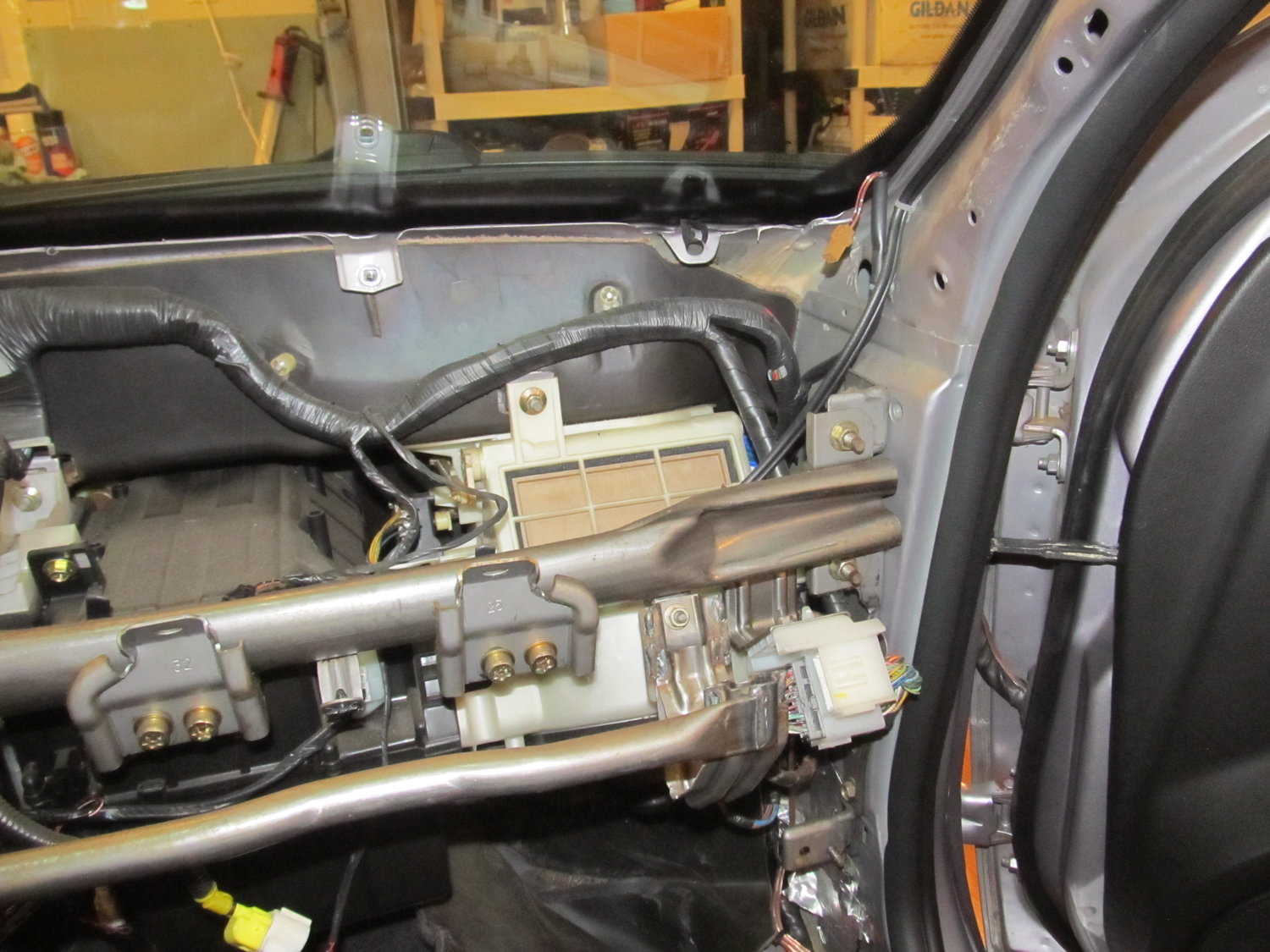
Looking in the glove box opening at the top, you will see a yellow wire harness connector. This is for the passenger air bag. It looks like you could pull either end out, but you have to pull the right side out to disconnect it.
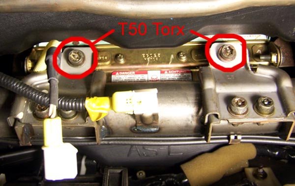
Now for the Torx bolts. Look up through the glove box opening and you will see 6 Torx head bolts. You only need to remove the 2 that are by themselves, not the pairs.
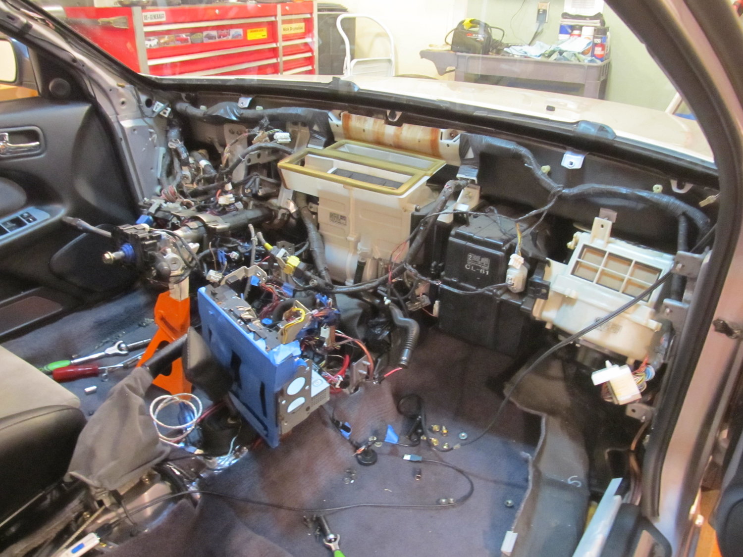
Once you have these 2 Torx bolts out, the dash is free and ready for removal. I did it by my self, but if you can get a helper, it is no doubt a lot easier. You have to pivot out the bottom edge a little bit and then pull back and up. There are guide pins built into the top front edge of the dash that require you to pull the entire dash back evenly. Because of the airbag, the right side has probably 75% of the weight.
For what ever it’s worth (in the category of useless trivia), I weighed the dash on my bathroom scale. It was 25.5 pounds. Most of that is the airbag.
Additional Reference Info
Thank you for not only making this thread with excellent pictures and descriptions, but for also keeping the pictures alive for all to view! It helped me out a great deal today when I removed my dash. I now have some questions about the heater core and blower motor:
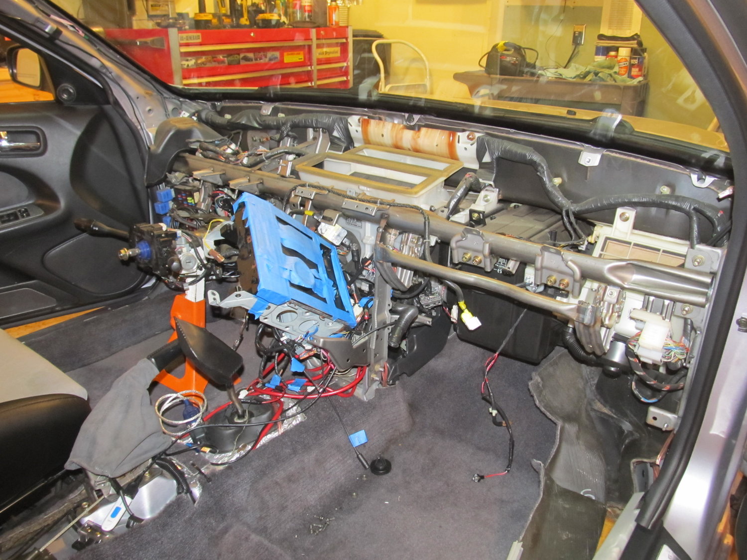
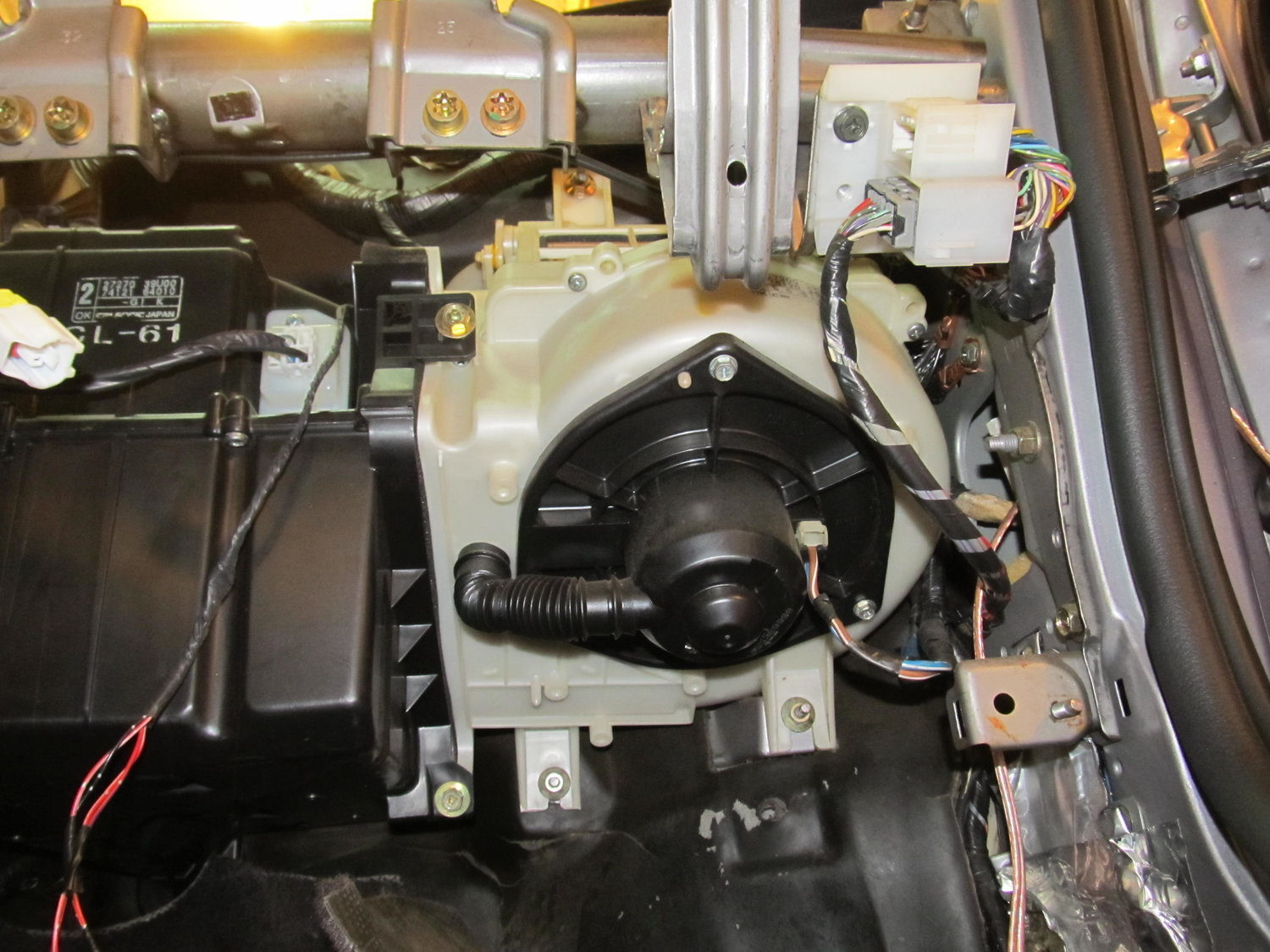
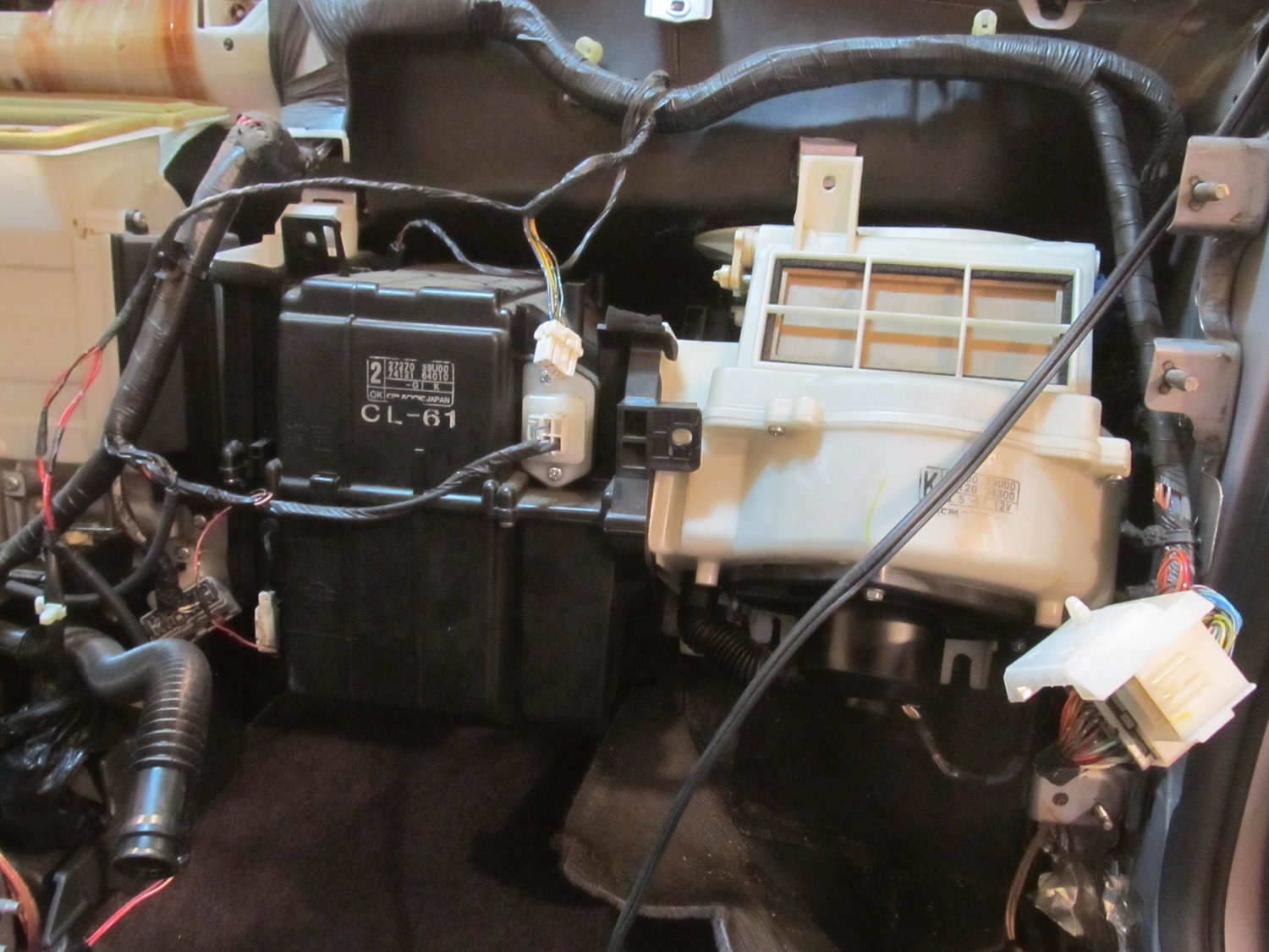
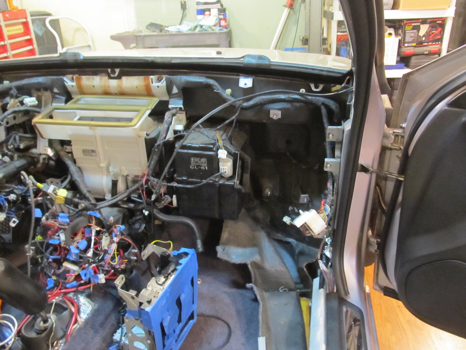
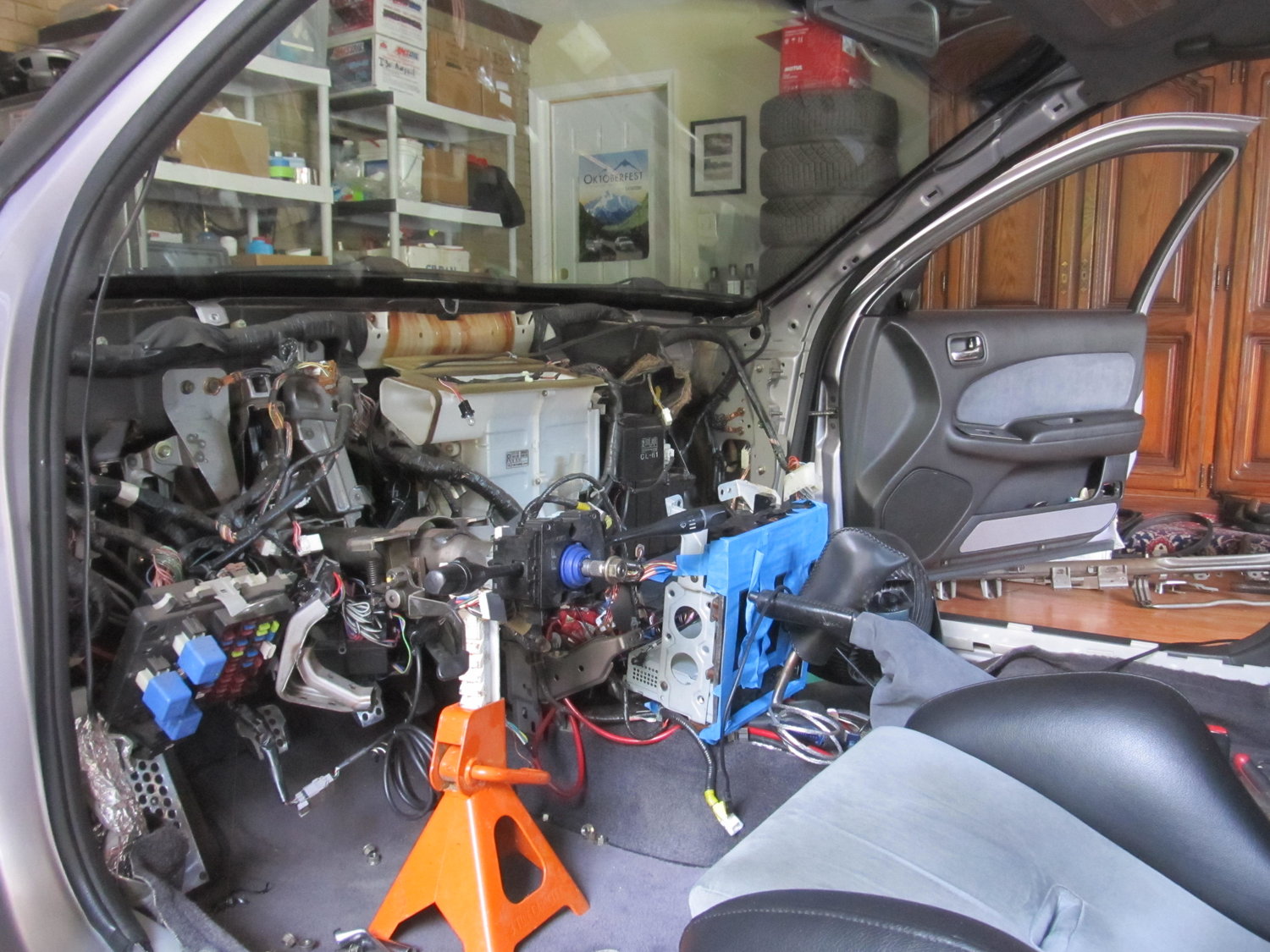
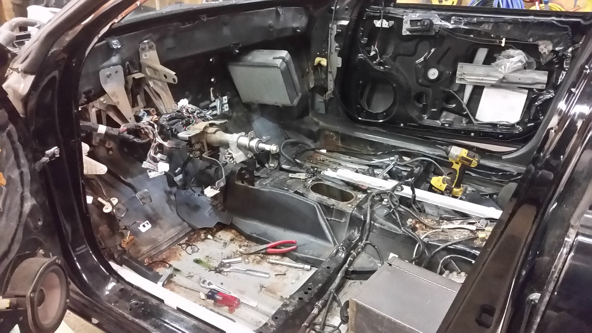
I’m trying to track down a water leak that’s coming down the corner behind the blower motor on the firewall. I’m really hoping I can remove the blower motor (the white thing on the right) without removing the whole heater core (black part on the left). I’m really not trying to drain all my coolant and my AC lines. Does anyone know if it can be done? Without removing the blower motor, I can’t get to any of the seams on the firewall. So close, but so far!
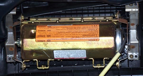
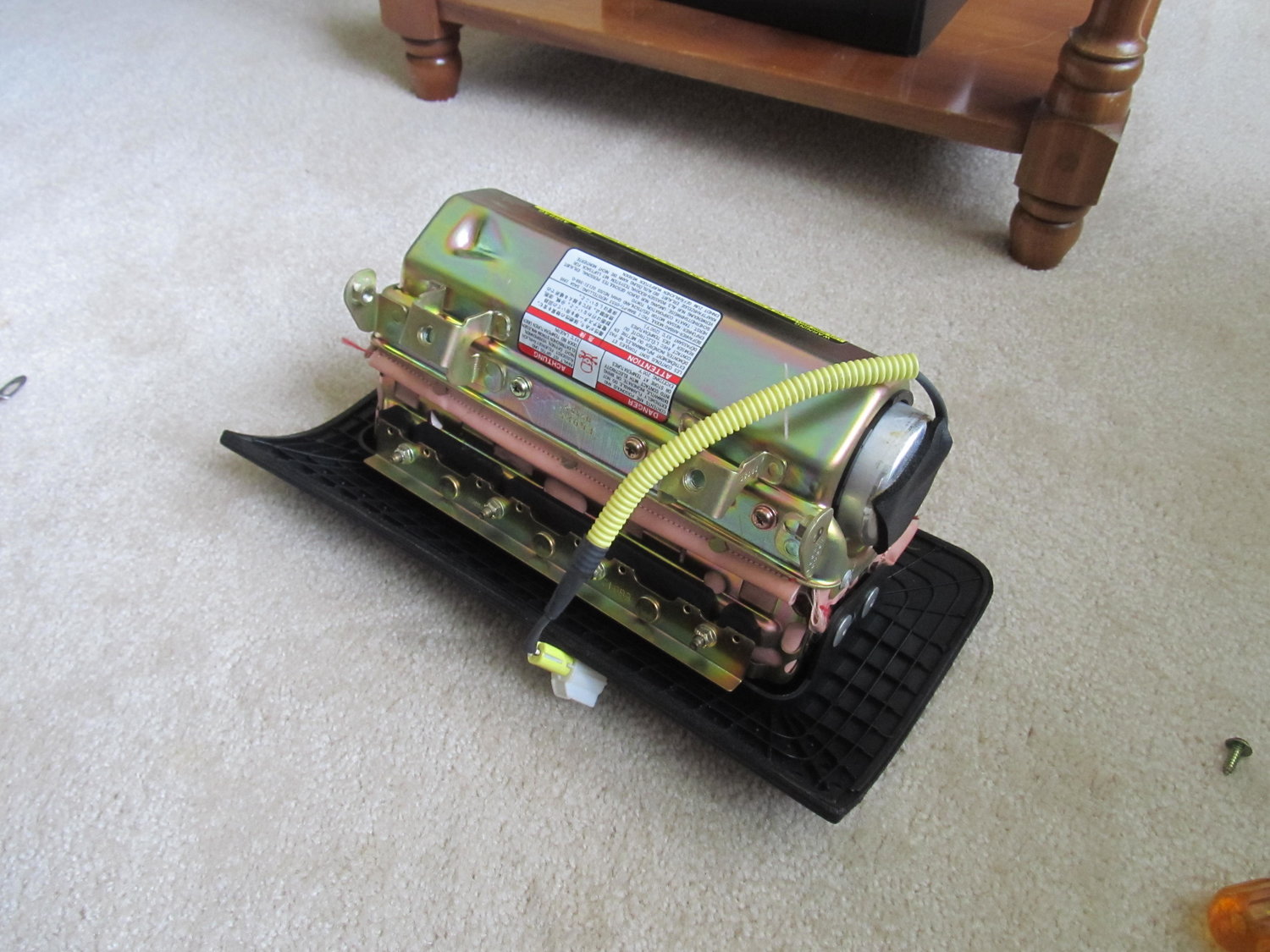
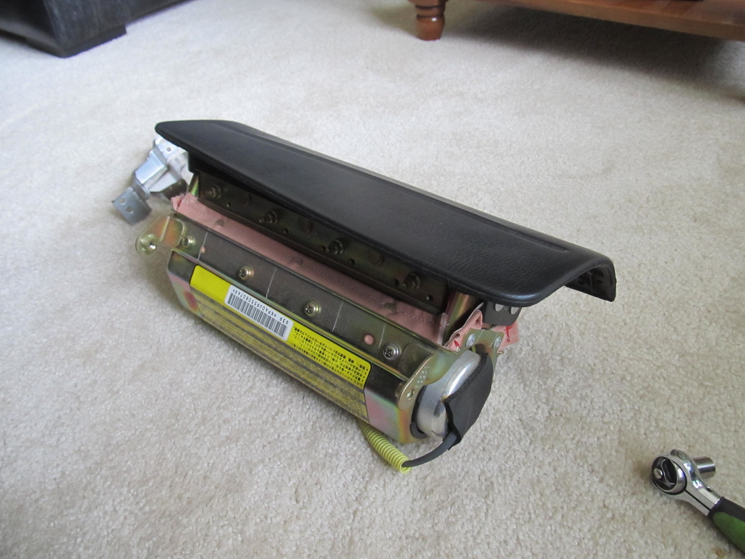
I would also like to remove the PS air bag, as I don’t have one on the DS, which disables the PS one, so I might as well get rid of it. Except it seems to be “one piece” with the outer cover:
There are a bunch of bolts and four rivet things, but without the air bag’s brackets, there’s no way to properly reinstall just the cover. Does anyone know if this can be done, or if I just need to keep the air bag?
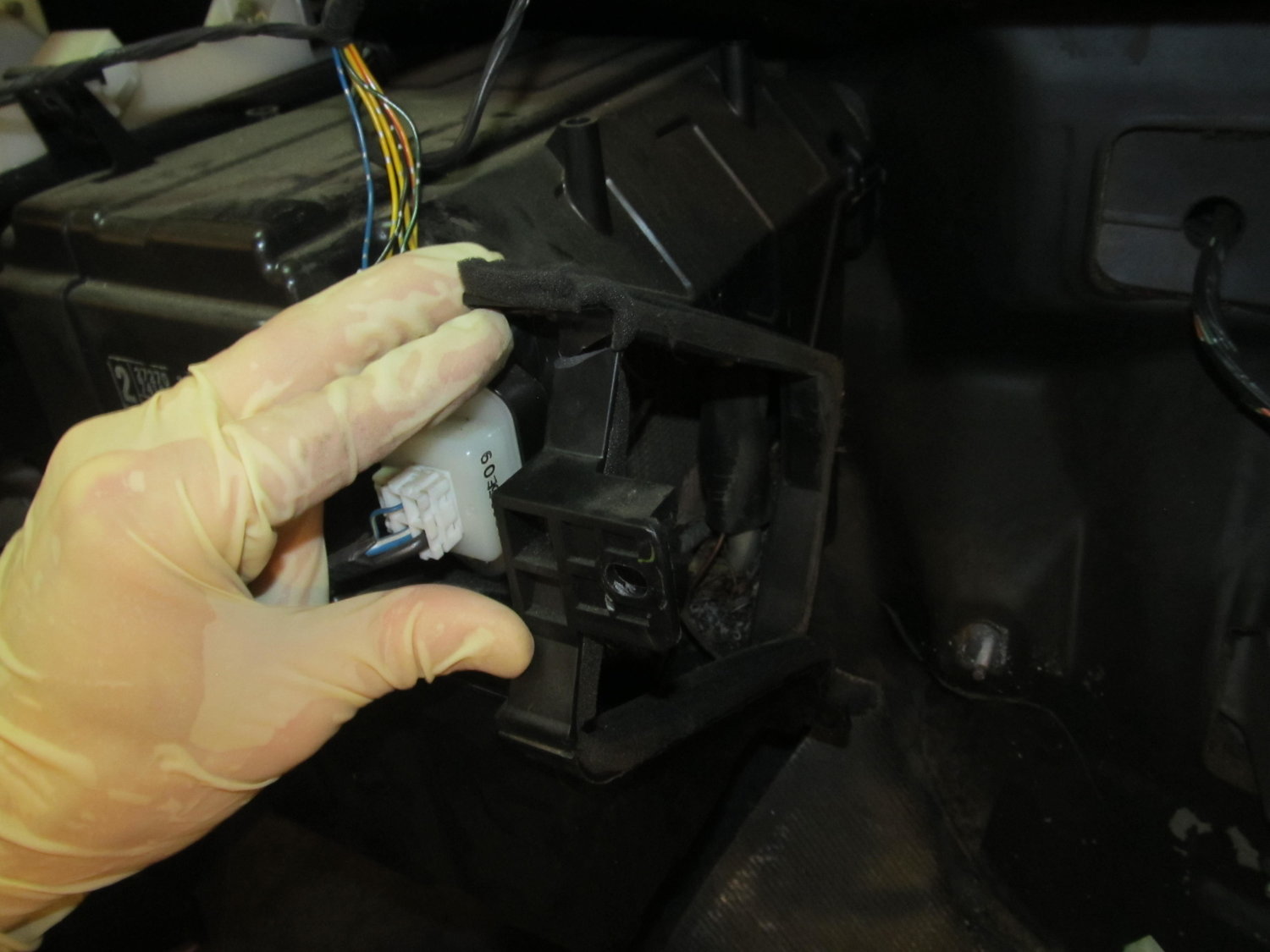
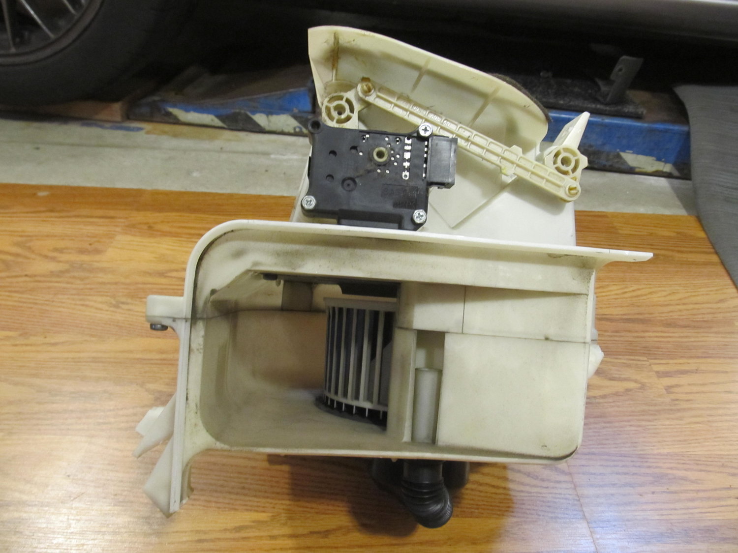
Well I got the blower motor out without removing the AC evaporator in the black box to its left! I was under the impression that the black box housed both AC and heater stuff, but upon looking at the lines from the engine bay, it became clear that the black box only held AC stuff. The main blower assembly in the center is what houses the heater stuff I guess. I do have the ability to recharge the AC, but it’s not something I’m very good at, and I didn’t feel great about venting my whole system to the atmosphere. So I hoped and prayed that I would find a quick and simple way to get out the blower by itself. I went back into the garage this morning pretty worried about what the day had in store. I had the idea that I might want to trim off some plastic from the black box to give me enough room to slide out the blower. I was in there looking at it, and noticed that one of the sides for the black AC box was pretty flimsy. With almost no effort, I was able to snap off a good piece of it. I then followed up with my snips, and with that little bit of plastic out of the way, I could get the blower out! It was a joyous moment to be sure. Here’s what I did:
That little bit of plastic was all that was keeping me from getting the blower out!
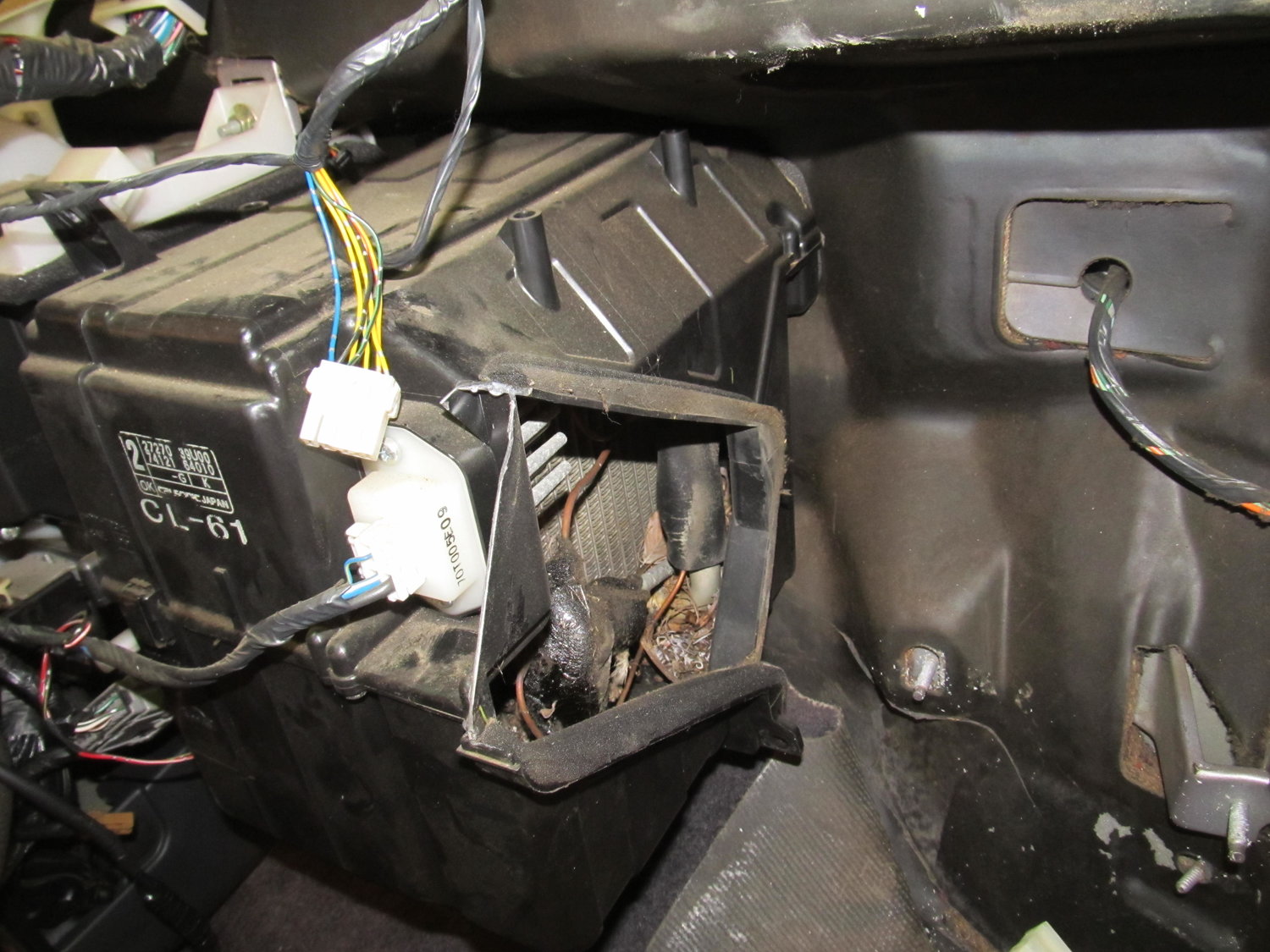
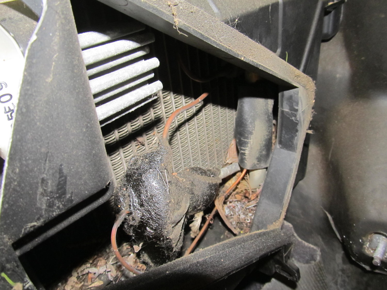
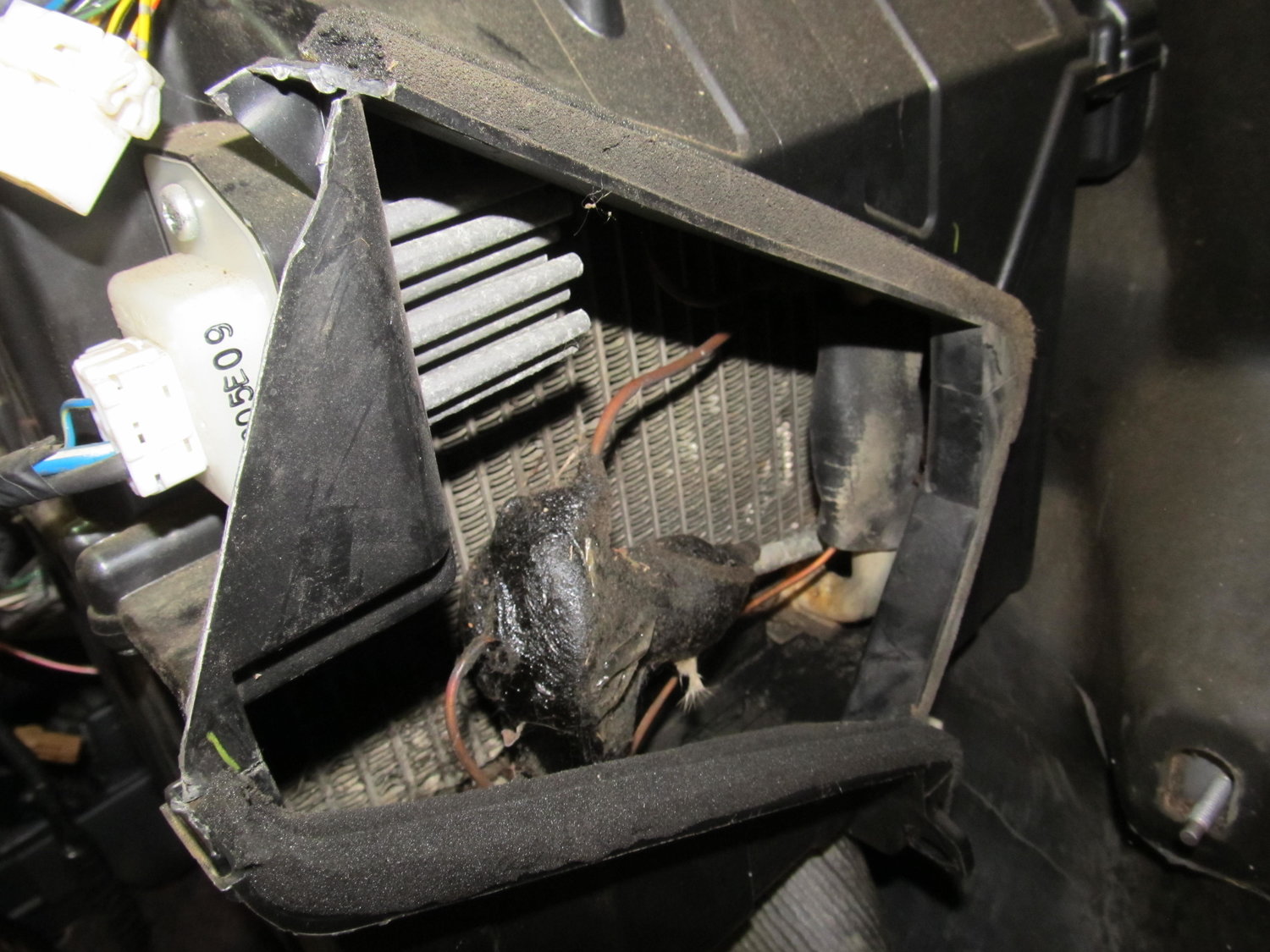
As this out of focus picture shows, there was a good amount of debris in the evaporator housing:
So I spent some time with different picks and my shop vac and cleaned it all out:
The blower was actually very clean:
So I was then left with this:
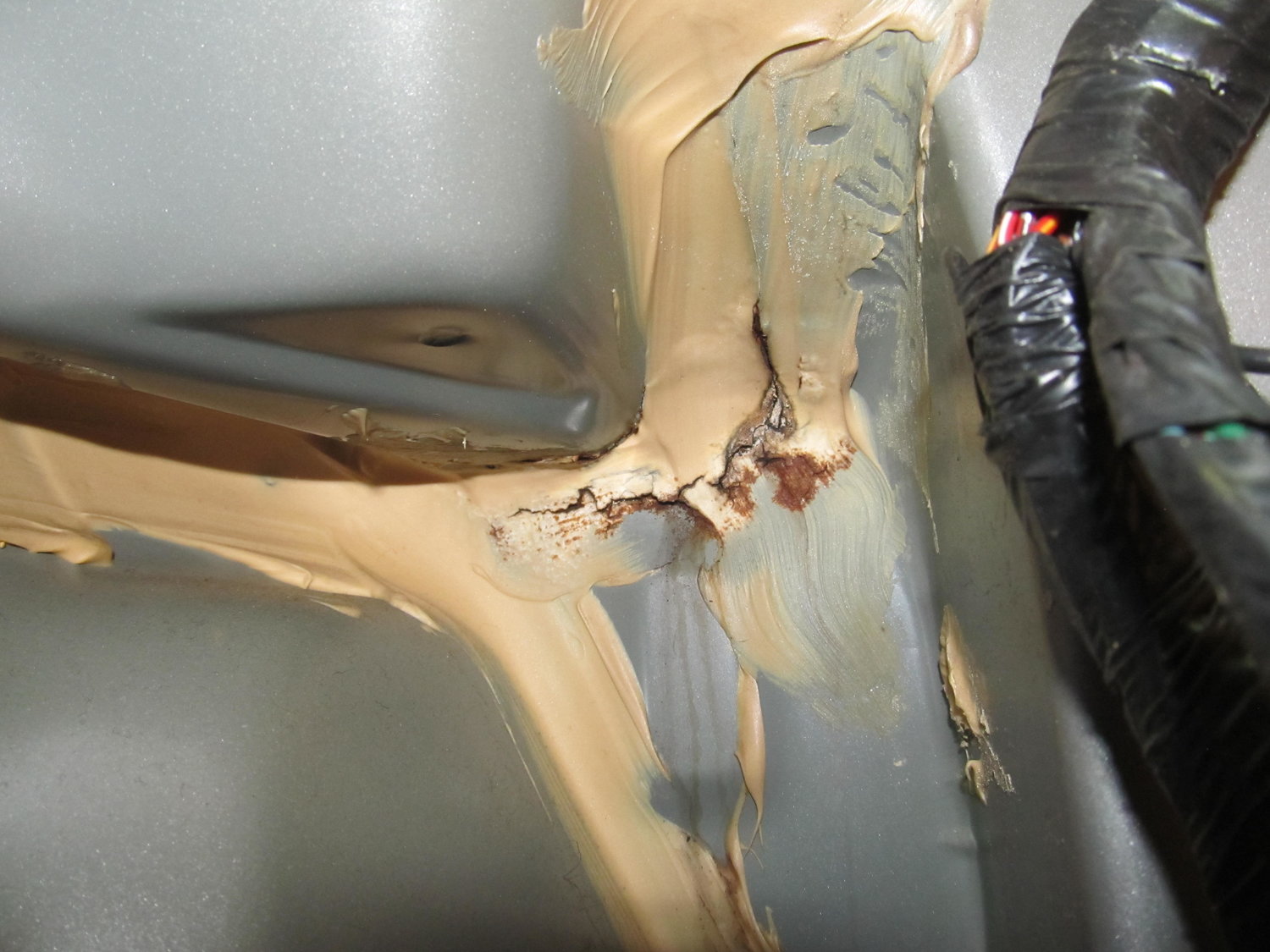
But there was still the factory insulation in the way. I ended up just cutting off a piece so I could get easy access to where I thought the leak was (I’ll reinstall properly when I’m all done). And with that, I was FINALLY able to see the source of my water leak:
It’s not in the exact same spot as the pics from schmellyfart, but it’s not far, maybe 2″ away. It’s clear that this area has a few body panels coming together, and it’s also right next to the drain for the cowl, so being sealed properly is crucial. If you have a water leak in a 4th gen, I wouldn’t be surprised to find it’s in this area! You can see three water trails coming down from that area, so I’m very confident this was my problem.
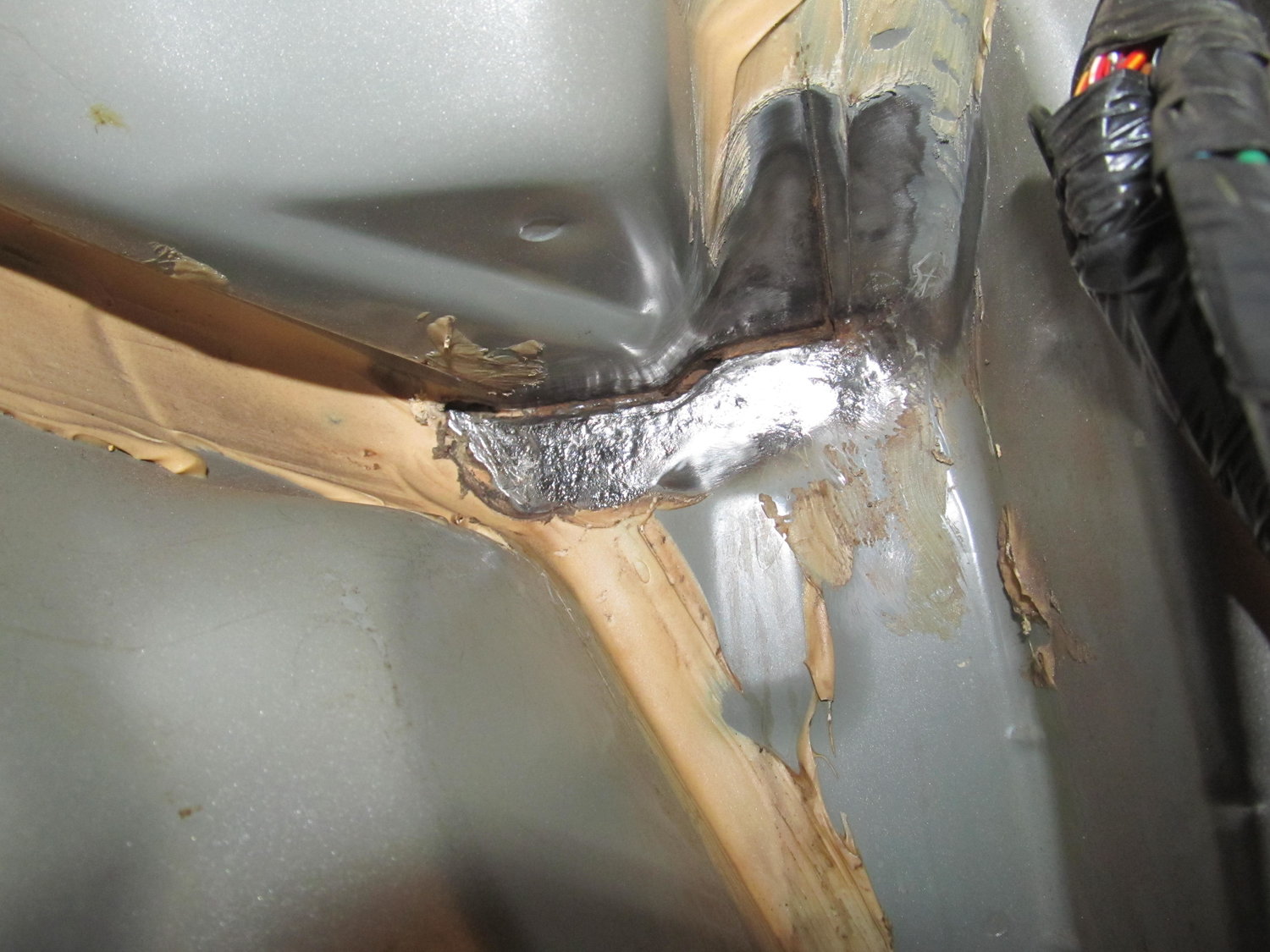
I spent quite a bit of time with different wire wheels, both on my big gun and little ones on my dremel, trying to peel back the old seam sealer so I could get a better look at exactly where the water is coming in.
It doesn’t really come through in the picture, but the horizontal area just right of center is actually completely open now. I had to scrape the old seam sealer out of it with a screwdriver, because I didn’t want any of that old cracked stuff getting in the way of my fresh seam sealer. Now I’ll be able to completely refill the gap with new sealer. Access into this area was pretty awkward, and my back was aching after a few hours in there, but I think I’m happy with how clean I was able to get it. When I finally couldn’t get it any cleaner, it was time to prep the surface for the seam sealer:
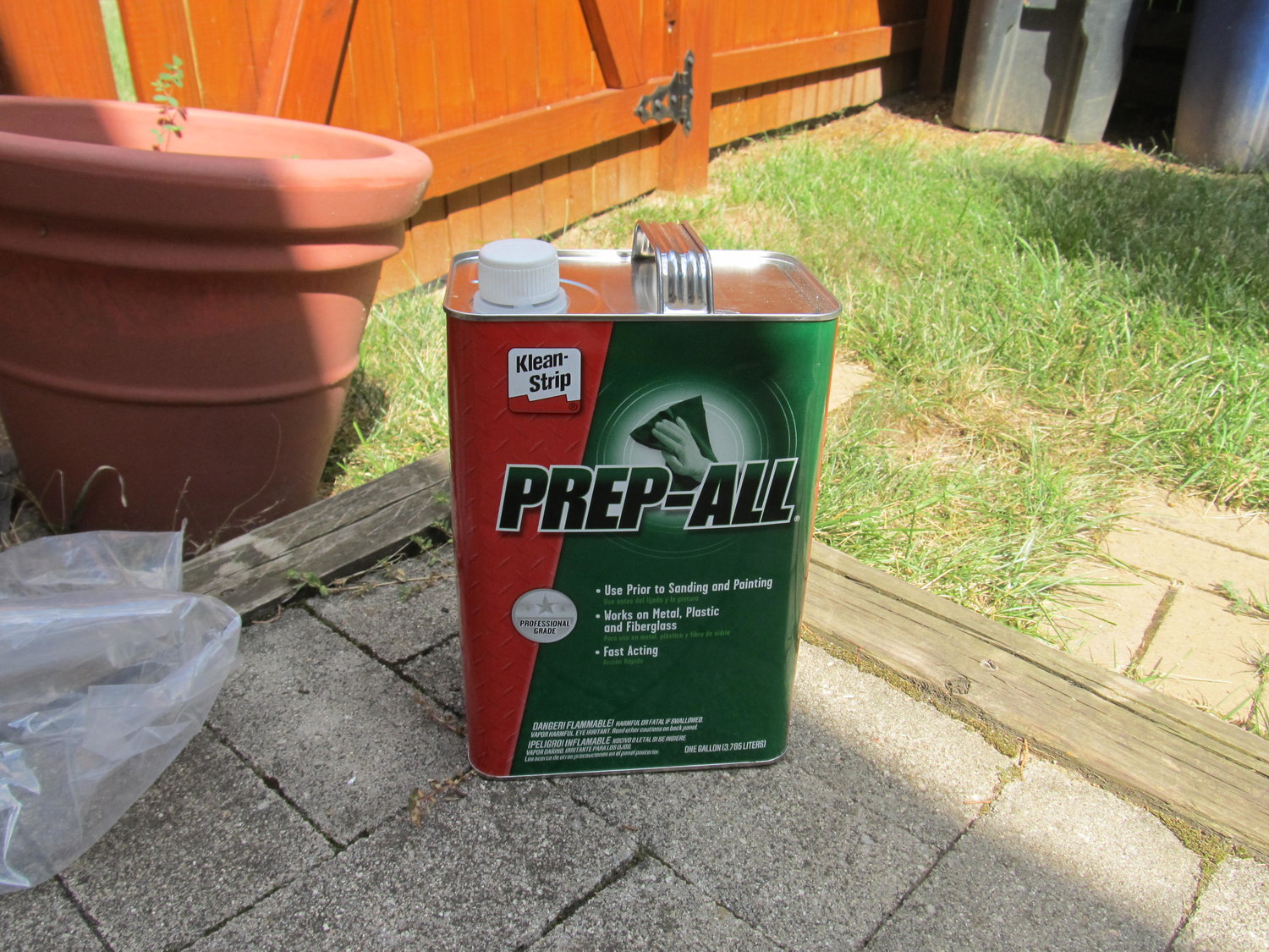
This stuff is SUPER strong, and has tons of warnings all over it. I go full-hazmat when I use this stuff, but professional painters swear by it, so I grit my teeth and bear it. I was considering applying the seam sealer today, but then I thought about it more and realized I would feel much better about it if I bought a new tube of it. My current tube is a few years old, and since I couldn’t get a firm answer on its shelf life, I decided I would rather spend another $20 on new sealer than to have my current sealer fail because it was too old and didn’t adhere properly. It should be here on Tuesday, so I’ll continue after that. But for now I’m feeling pretty damn good that I was able to get the blower out by itself without ruining anything!
I’m left with this to look at, and ponder how many things I’m going to forget to reinstall, or reinstall in the wrong order. I’m not out of the woods yet!
Now here is what the back of the clock unit looks like. If you look closely, you will see that EVERY wire is labeled and tells you what it is. All you have to do is hook it up to the correct corresponding wire.
Now this shows an exact picture of the wiring I have done. The RED wire from the SCANNER connects to the Yellow/Red wire. The YELLOW wire from the SCANNER connects to the Green Wire (The picture shows me splicing a black wire, that is because I had to extend the original yellow wire from the scanner.) The last wire left on the scanner is BLACK, that I just grounded to the sunroof bolt under the sunglass holder. No need to extend that wire all the way down to the clock unit for NO reason.
This will work and is the correct way to wire the scanner. It will blink or do whatever pattern when the car is off or armed. When the car is turned on, the scanner turns off.
Hope this helps and solves everyone’s problems. Simple install, but I think some of you got confused. Now everyone can have knight rider style SCANNERS.
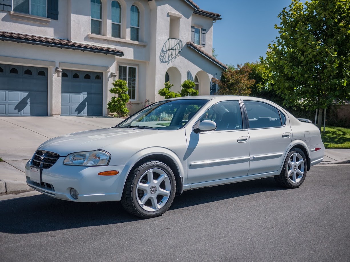
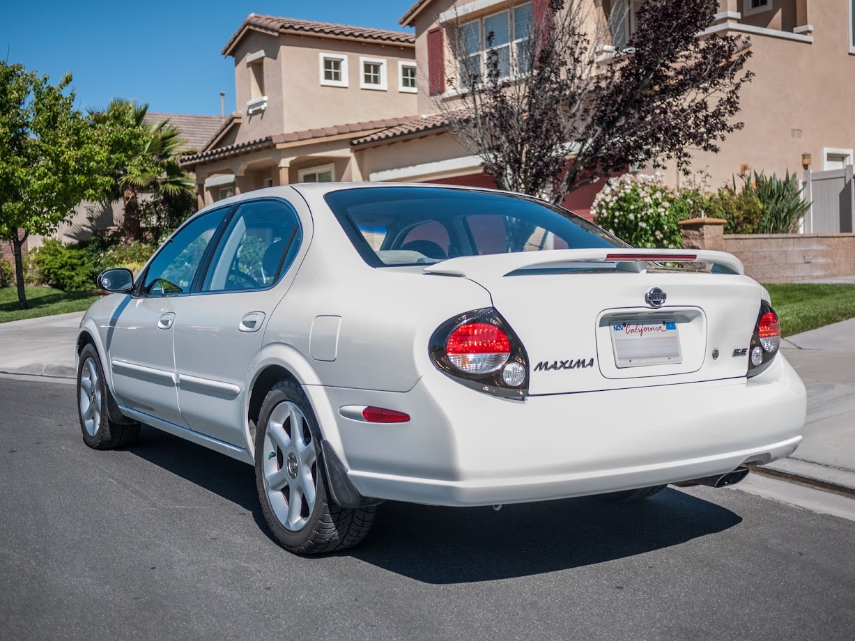
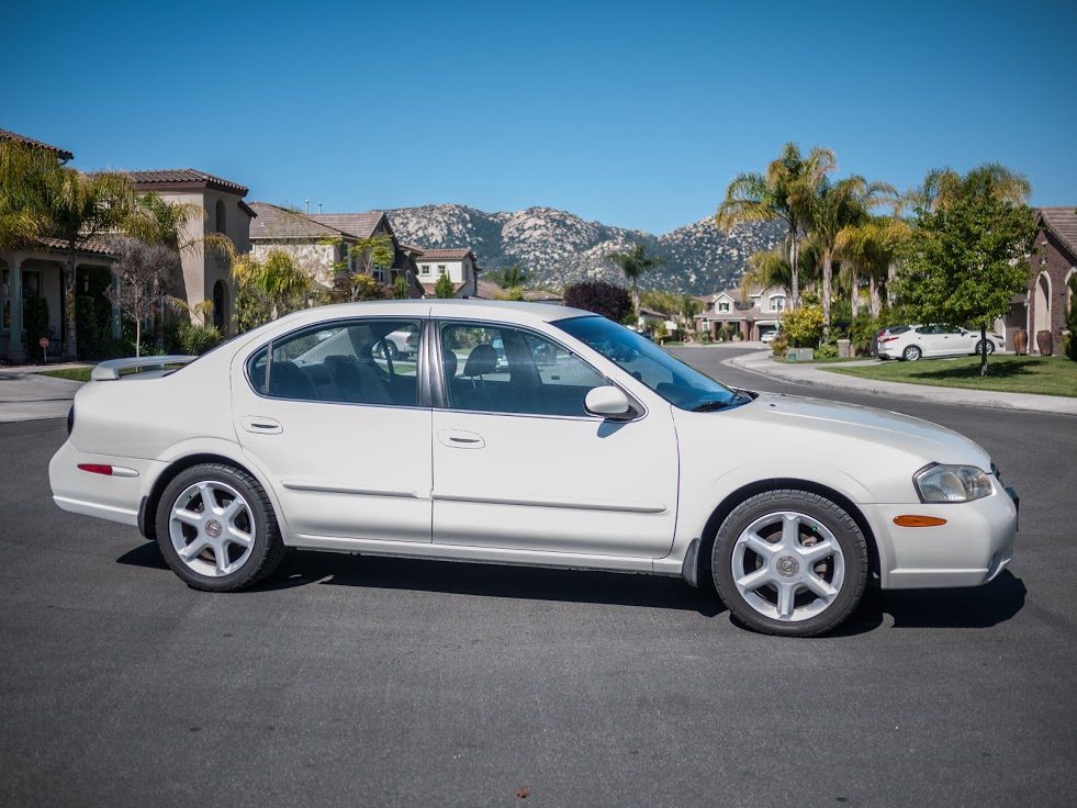
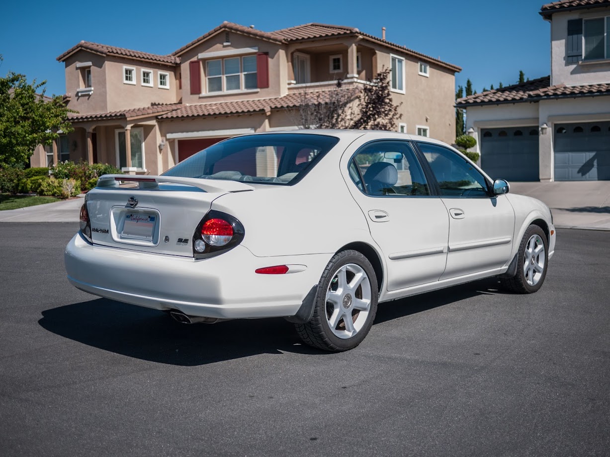
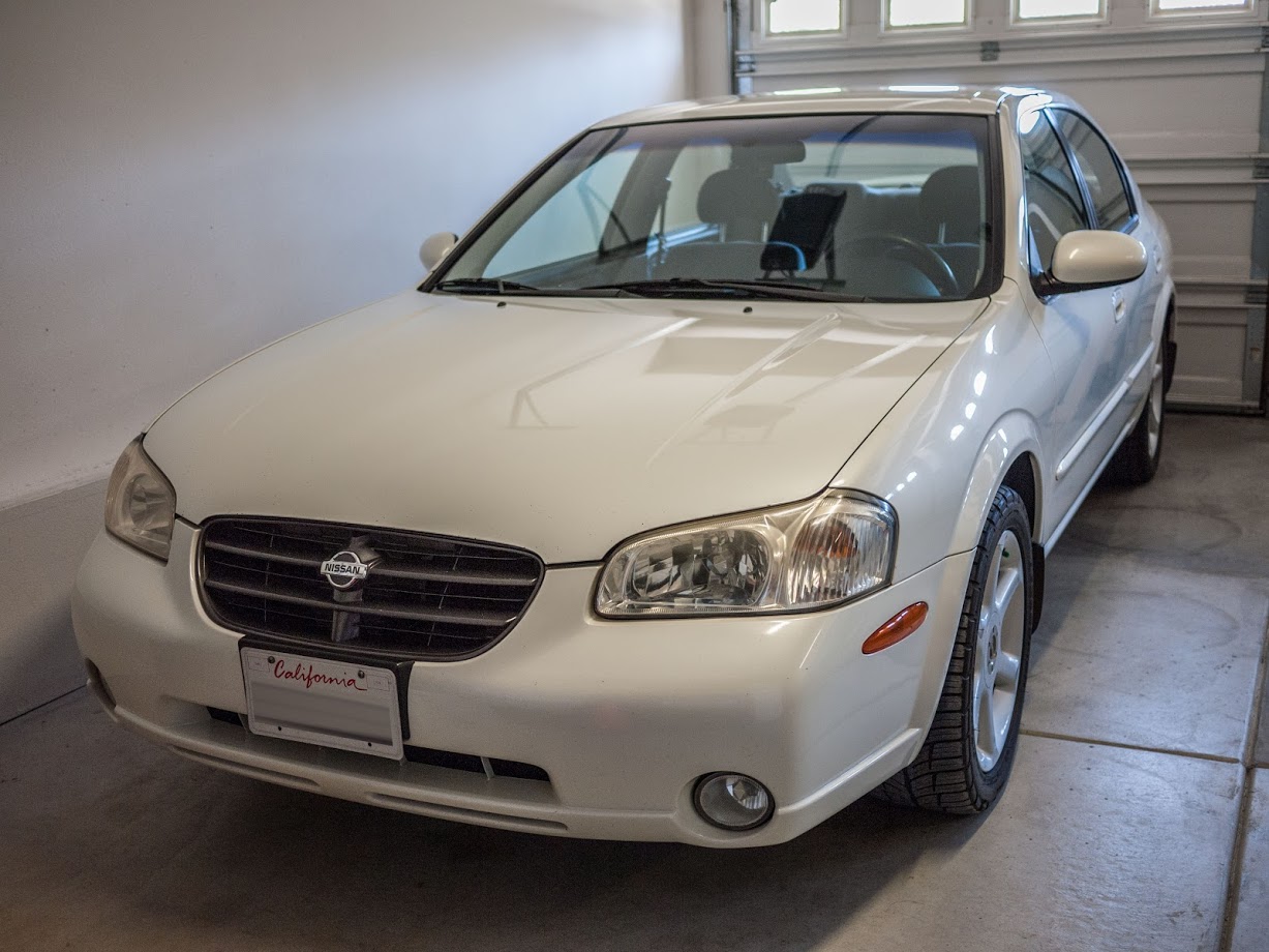
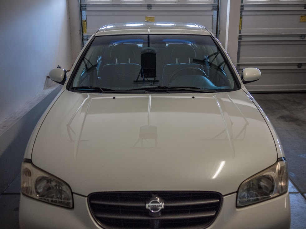
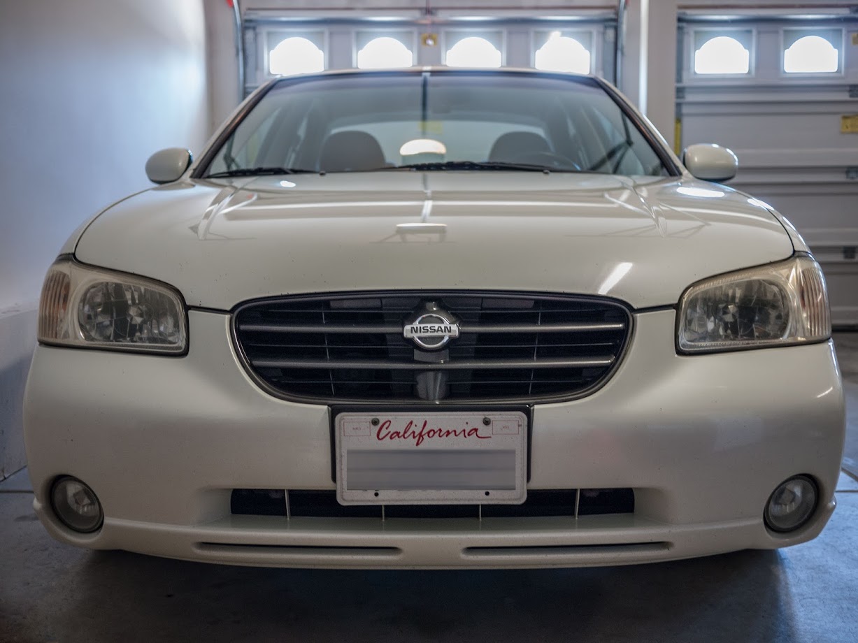
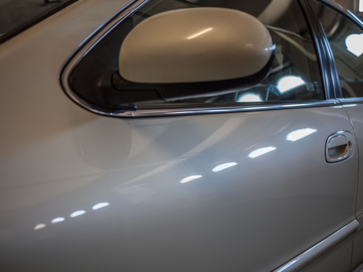
Car Photos
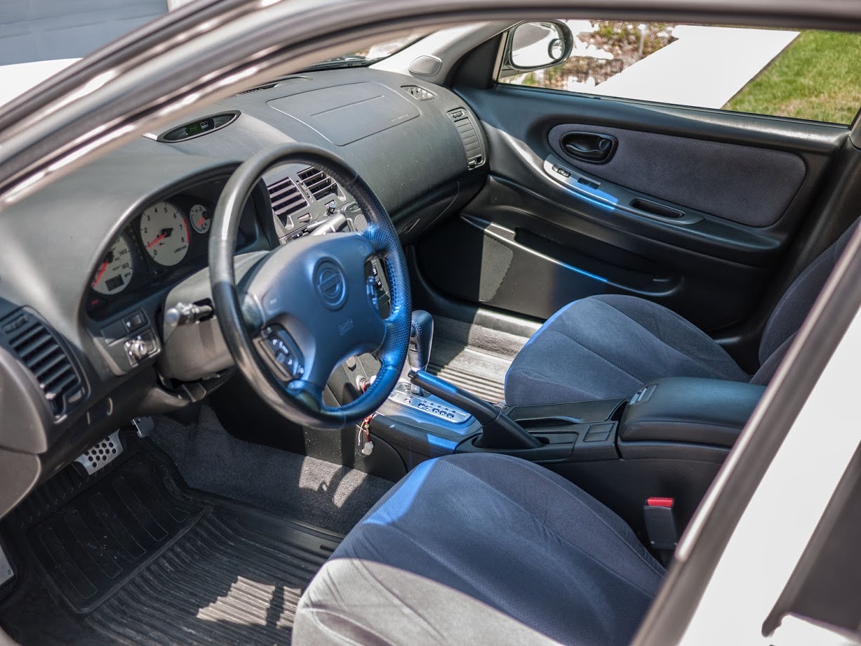
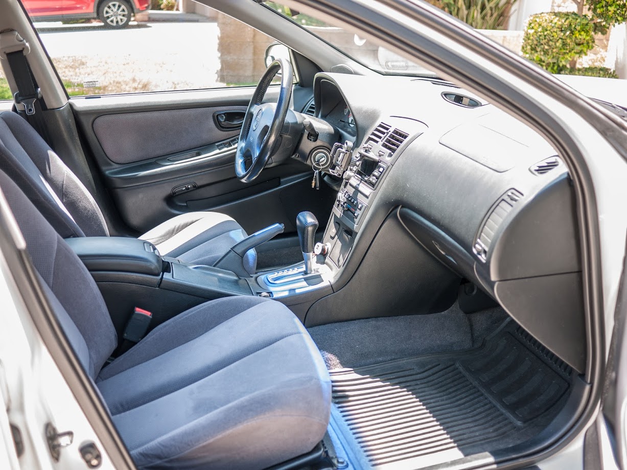
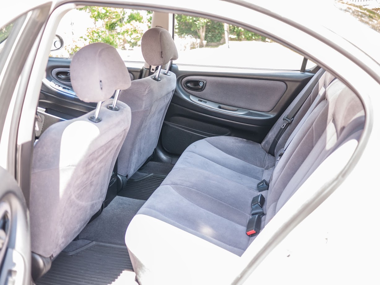
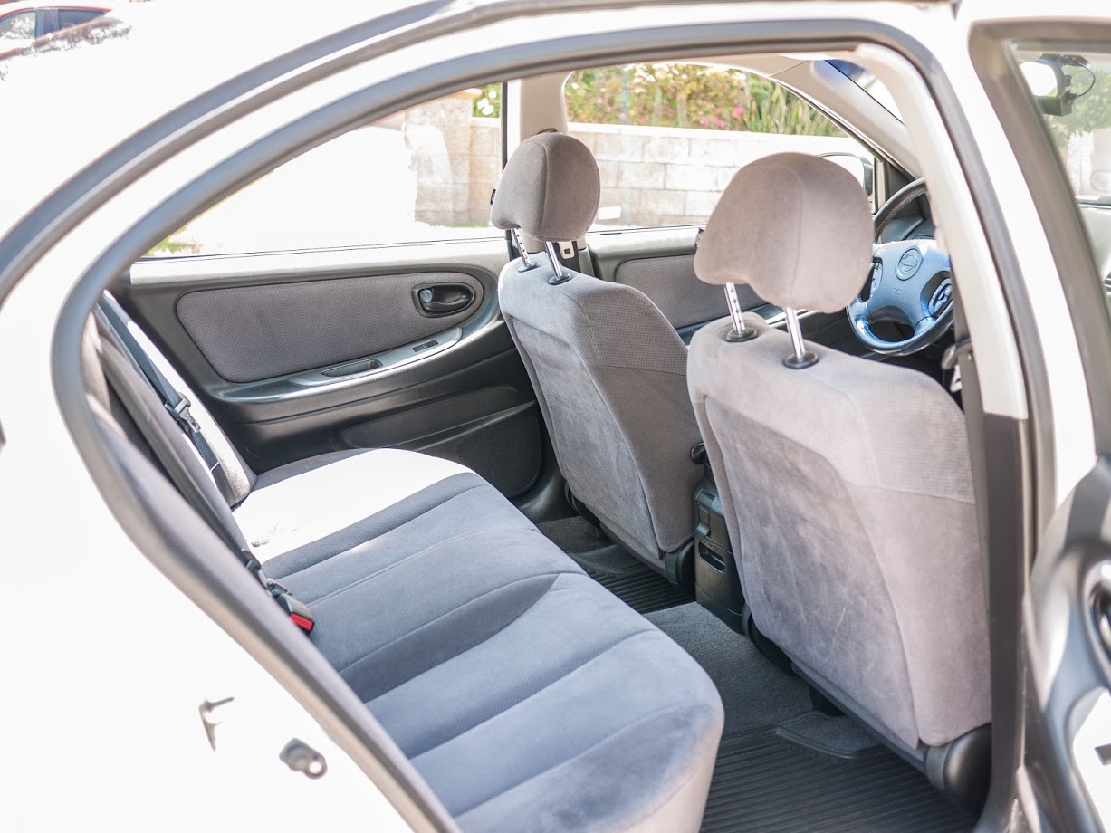
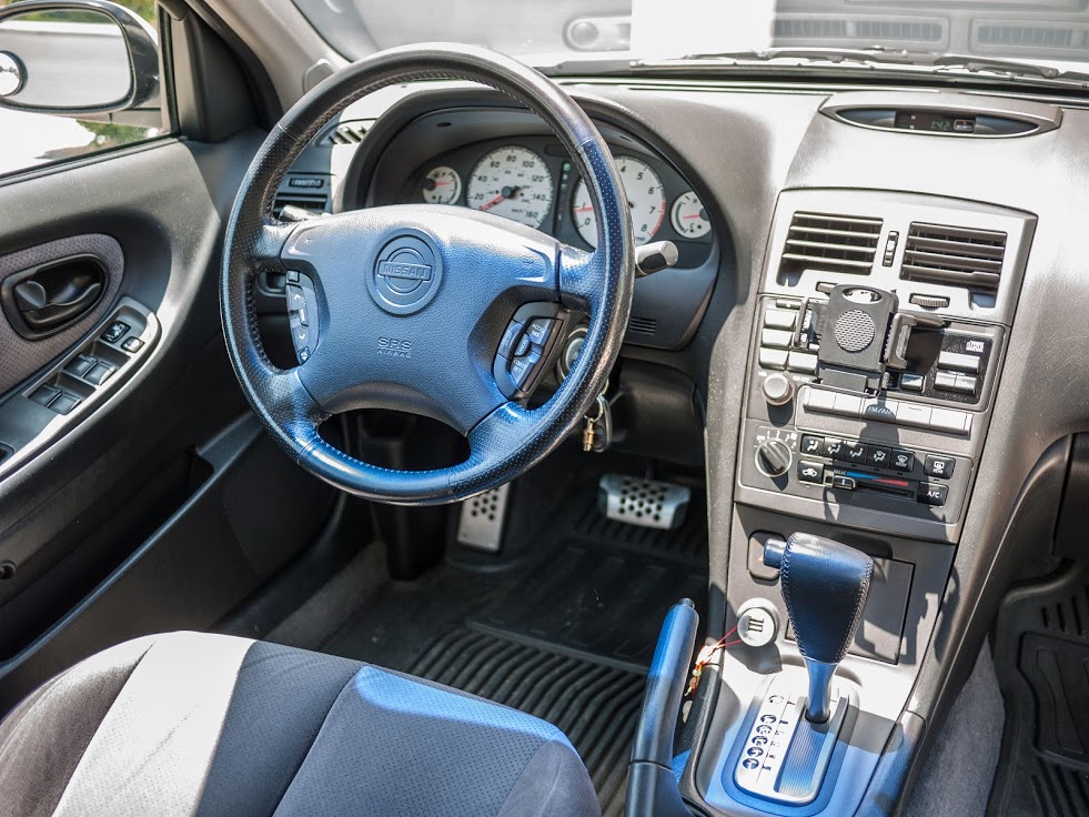
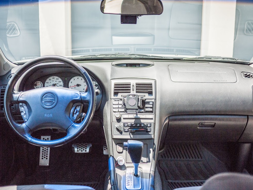
I’m the original owner of this car. She is a 2001 Nissan Maxima SE with an Icelandic Pearl exterior and a Black interior with simulated perforated cloth trim and seats. At the time, I actually had her custom ordered at the dealership, so she wasn’t a dealer-upgraded / price-hiked model that was just sitting on the lot for me to pick.
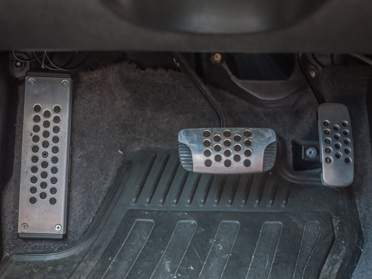
I’ve never really modded her except for a generic FSTB, a Progress rear anti-sway bar, and swapping out the stock 16-inch wheels with the 17-inch ones from that model year. As for interior mods, I have the chrome door sills, OEM rubber floor mats, and 350Z dead pedal with Anniversary Edition pedals. I do have the Anniversary Edition shifter too, but I haven’t been motivated enough to install it. For electronics, I have a GROM Audio adapter which allows me to have Bluetooth while keeping the steering wheel audio controls and a YI 4K Action Camera that I use as a dash cam.
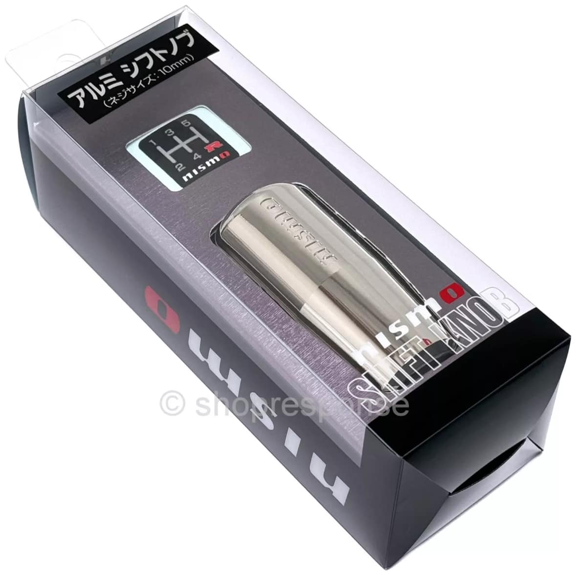
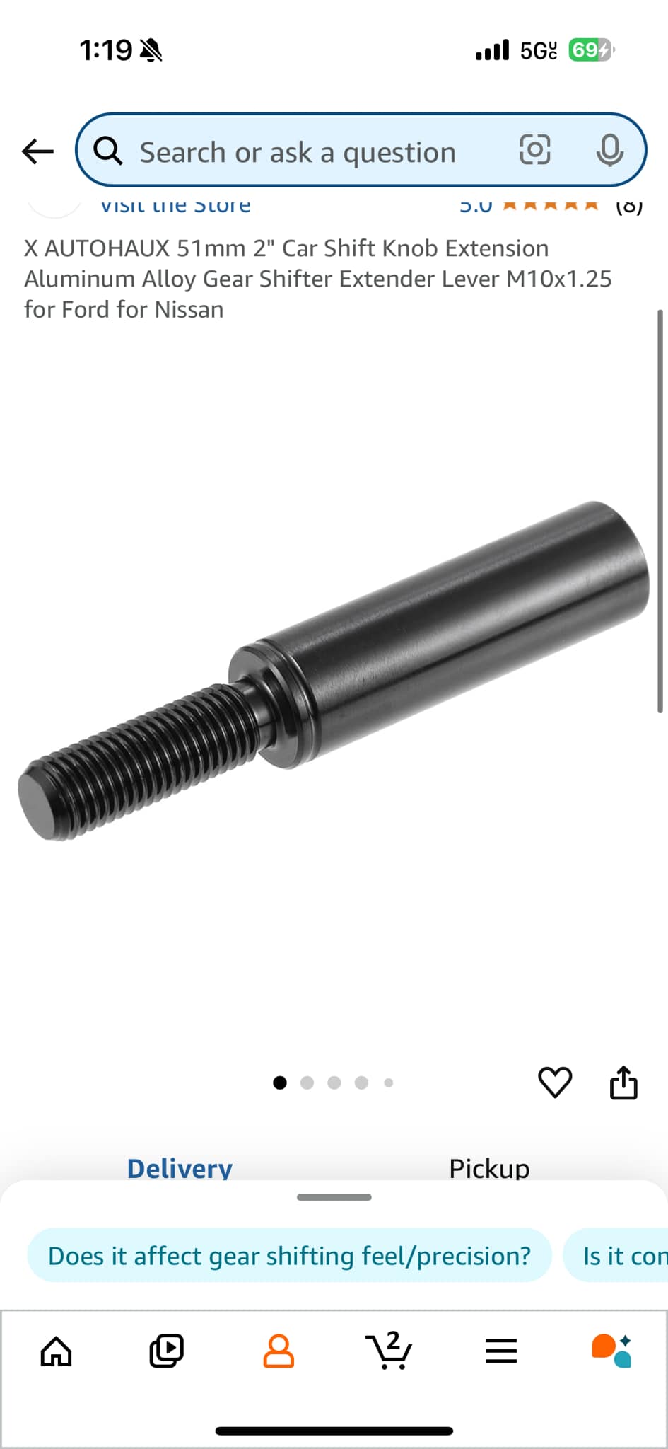
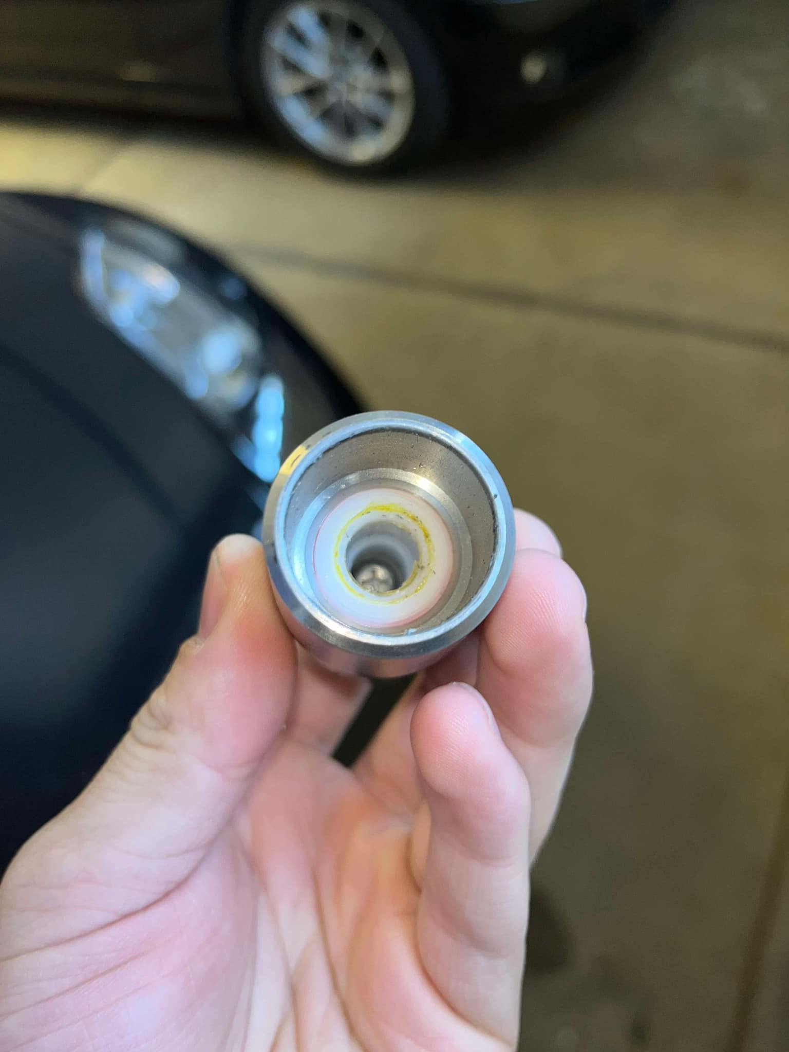
Part number C2865-1EA0: I wanted to see if this shifter would fit since I used to have it on my Sentra SER back in the day. Unfortunately, it does not. The base of the knob is too small in diameter to clear the shifter’s top collar, so it can’t thread onto the shifter without an extender—the shortest one I could find is 2 inches. It’s possible to cut the extender to make it sit flush on the stick. That said, I’ll be selling this knob along with the extender if anyone wants to try making it fit.
Part 2:
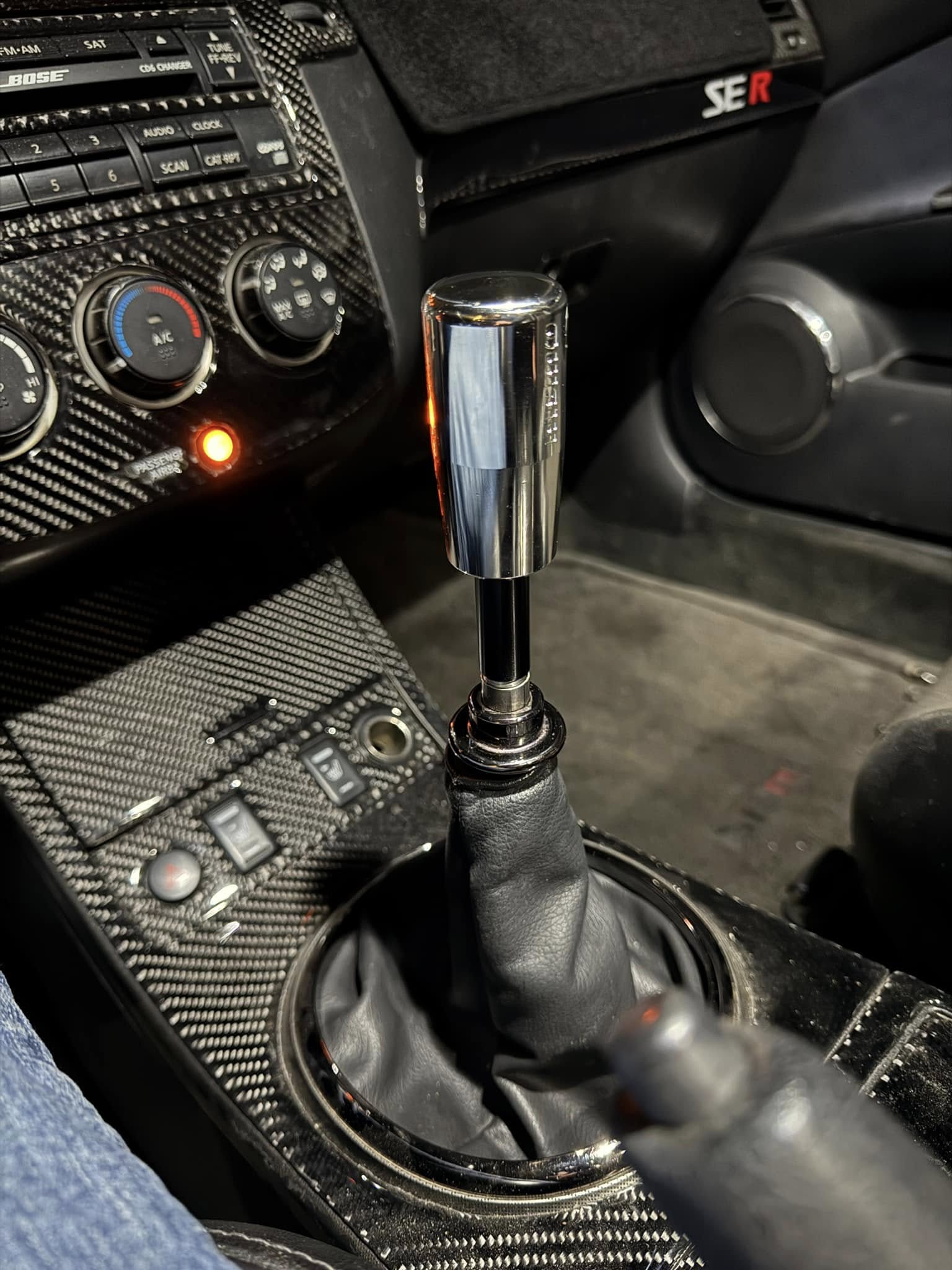
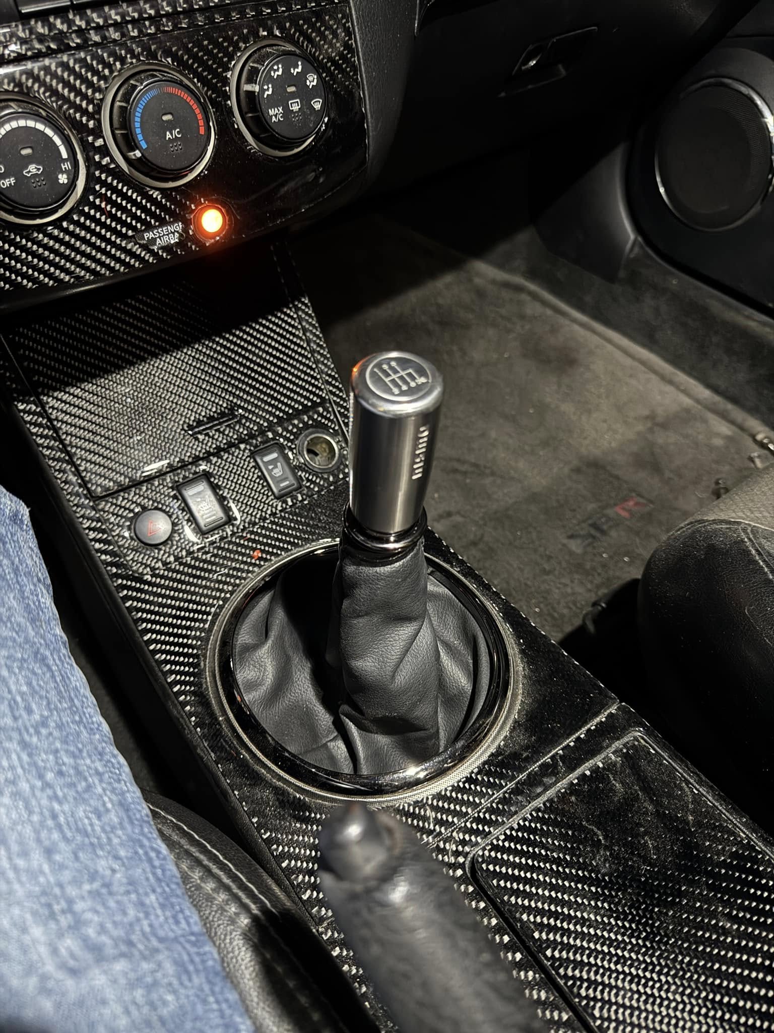
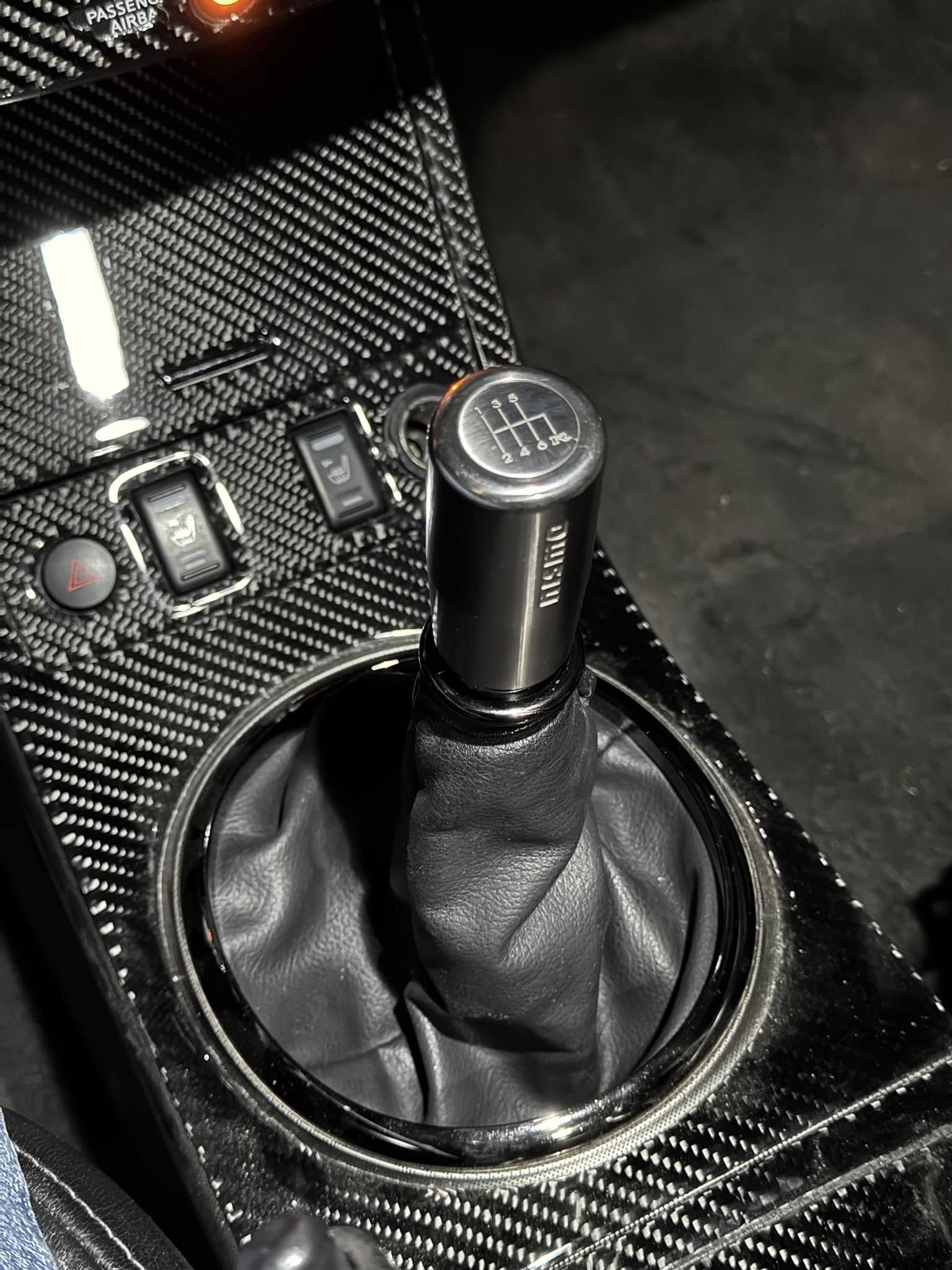
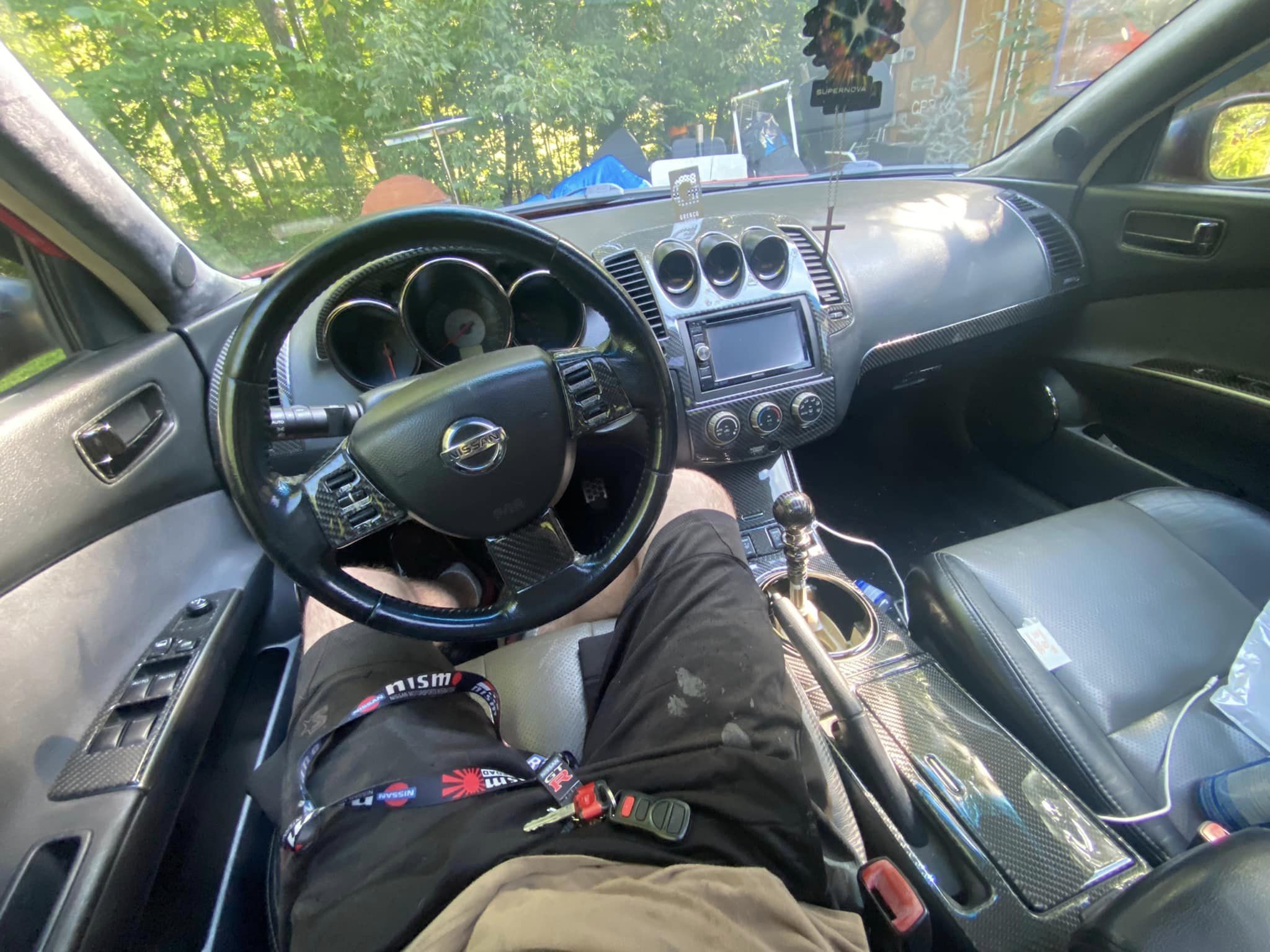
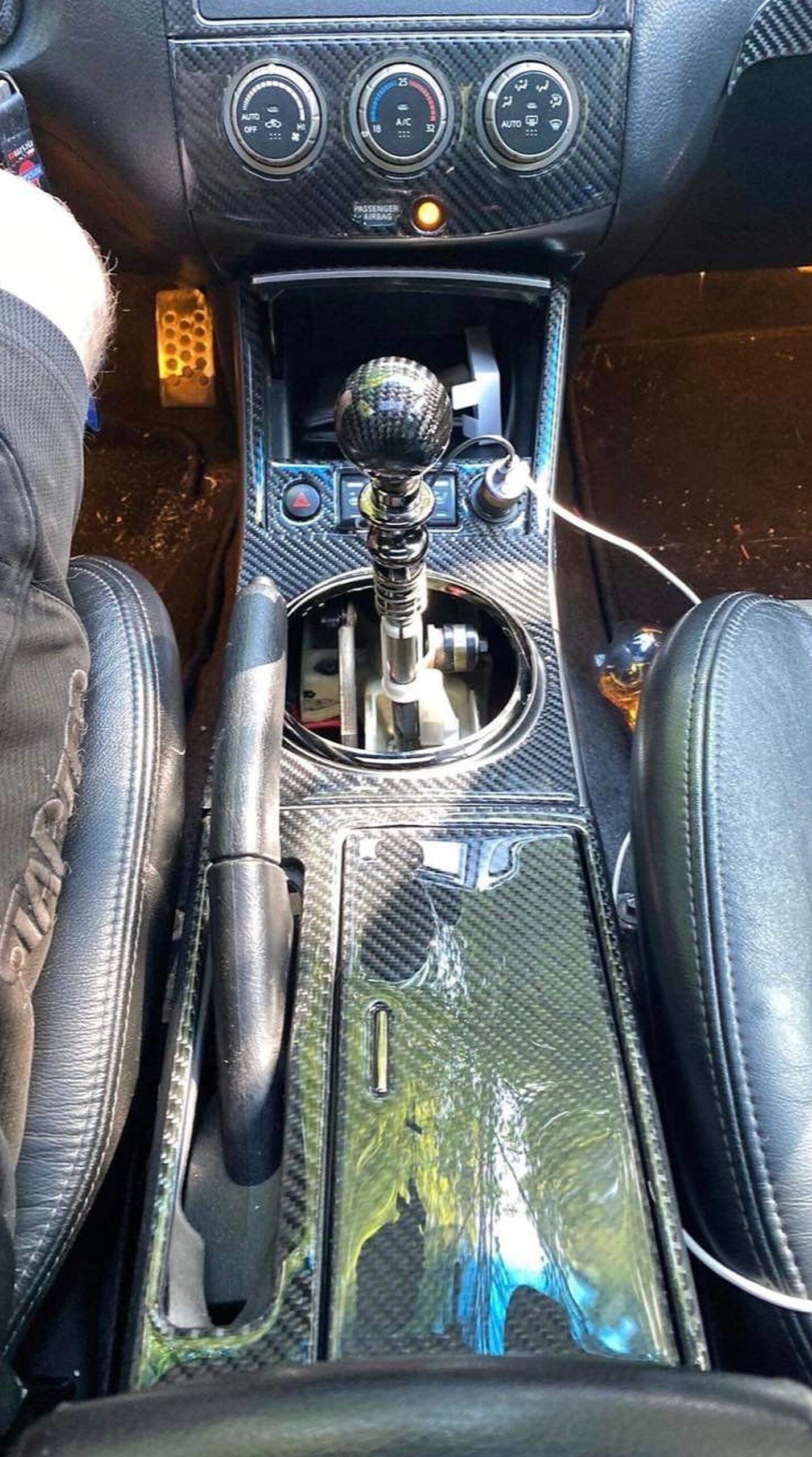
I’m not sure of the part number for this shifter since I bought it used. It came off a 350Z with an OEM Nismo knob. I wanted to see if this one would fit better because its wider base diameter should allow it to clear the shifter’s top collar—and it does! The only “modification” I had to make was adding two 10mm washers to the OEM shifter where the knob threads on. This prevents it from threading down too far, which would interfere with the pull-up reverse lockout. This shifter sits much better, and I’m stoked I found it!


")


")


 Now this shows an exact picture of the wiring I have done. The RED wire from the SCANNER connects to the Yellow/Red wire. The YELLOW wire from the SCANNER connects to the Green Wire (The picture shows me splicing a black wire, that is because I had to extend the original yellow wire from the scanner.) The last wire left on the scanner is BLACK, that I just grounded to the sunroof bolt under the sunglass holder. No need to extend that wire all the way down to the clock unit for NO reason.