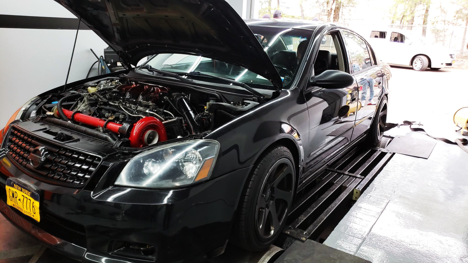
Member Credit: Streetzlegend via FastMaximas.com
In this post I will go over the process I went through when building my turbo kit. As many know, the car was first equipped with a rear mount turbo for many years.
Some information about the car:
- 1997 Maxima
- Automatic
- Turbo (initially rear mount turbo)
Rear Mount Turbo Preview
As a rear mount turbo, it was a great experience. It was my first time being in a turbo car much less driving one. I saw an episode of Powerblock on SpikeTV showing an installation of a rear mount twin turbo setup on a Corvette. Right away I started brainstorming and realized how easy it would be to do it. I started gathering parts and in a weekend we installed it. I went for my first drive, felt what it was like to get anything greater than 0psi and boy was I hooked. I will make a post soon about the details involved with the rear mount turbo.
- I used 370CC injectors to begin with.
- The turbo was a T04b with a .60ar T4 turbine.
- None Intercooled with Meth.
- 7-10psi
- Rear Mount Turbo Dyno VQ30-00VI
- (Expect a post about the rear mount soon)
- It made 299whp / 291wtq
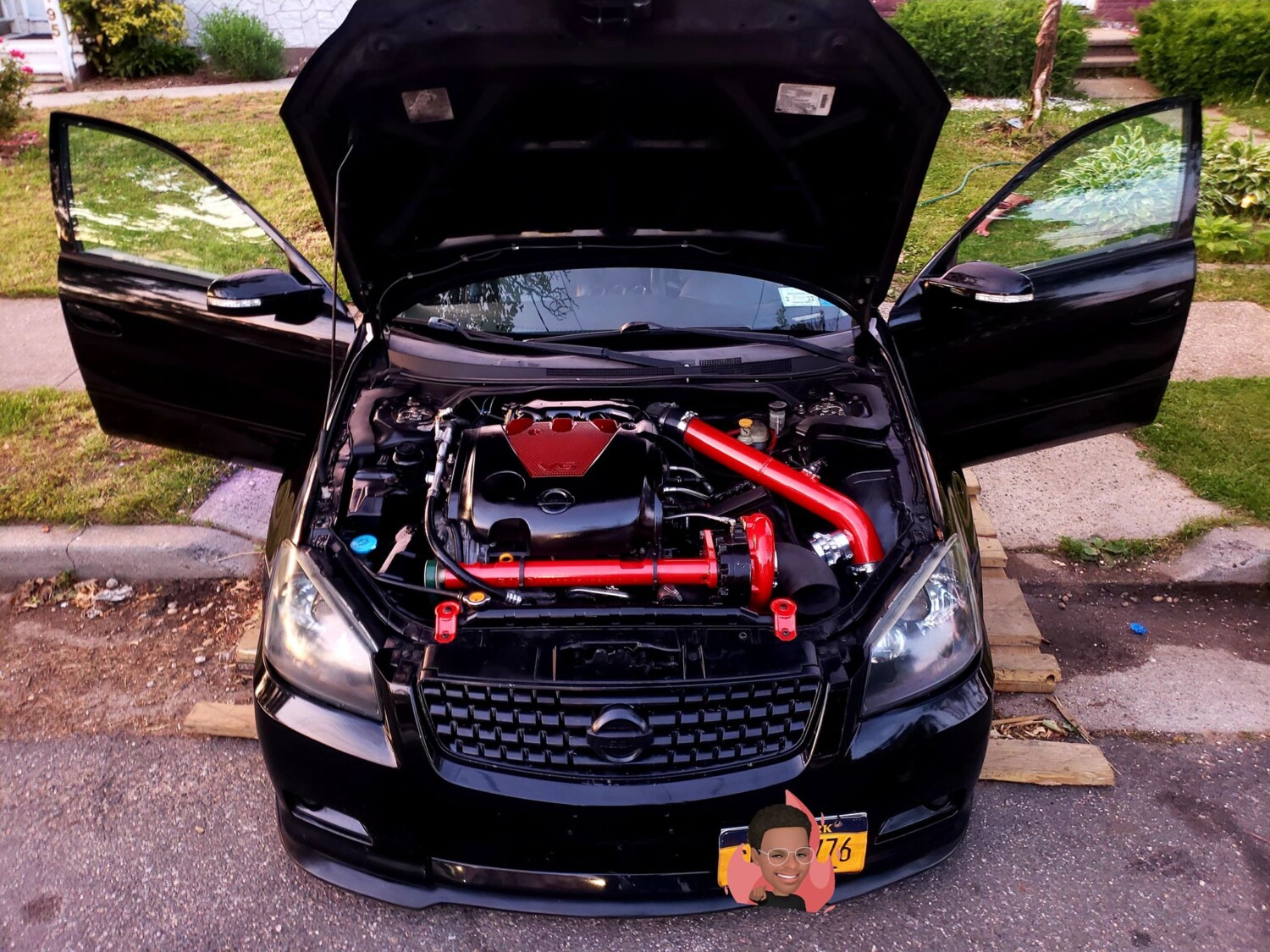
Front Mount Turbo Design
Fast forward several years and the car now garaged I was able to start gathering more tools and I was gifted a Harbor Freight 90amp Flux Core welder. Right away I started piecing together a front mount turbo kit in my mind. I started doing mock up 3D designs to get an idea and better visualize what I was going to do. I did not want to do the usual reverse y-pipe, or have to remove the battery, I wanted it to be efficient, and my own solution. This is the design I started with:


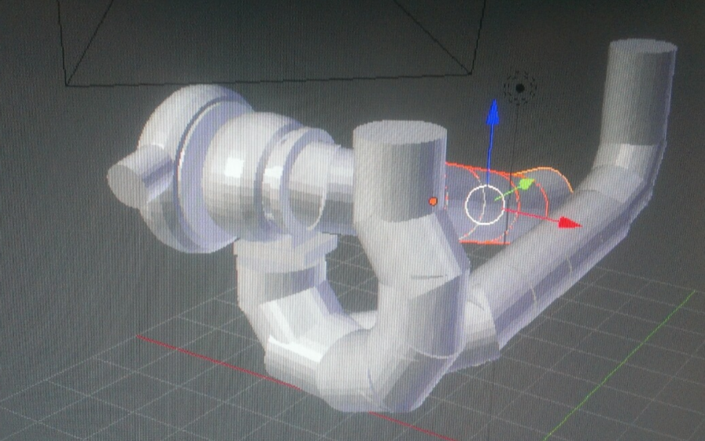
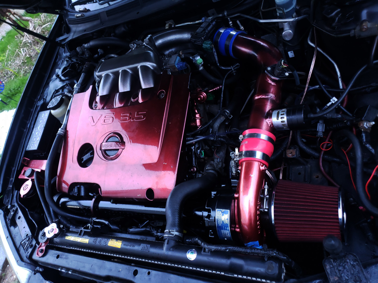
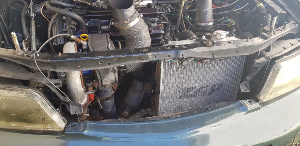
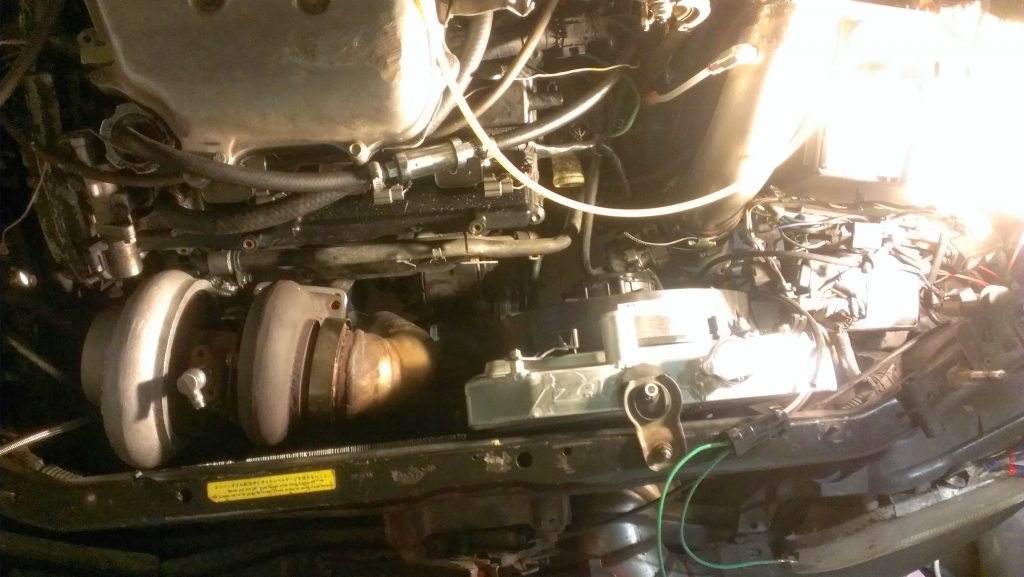
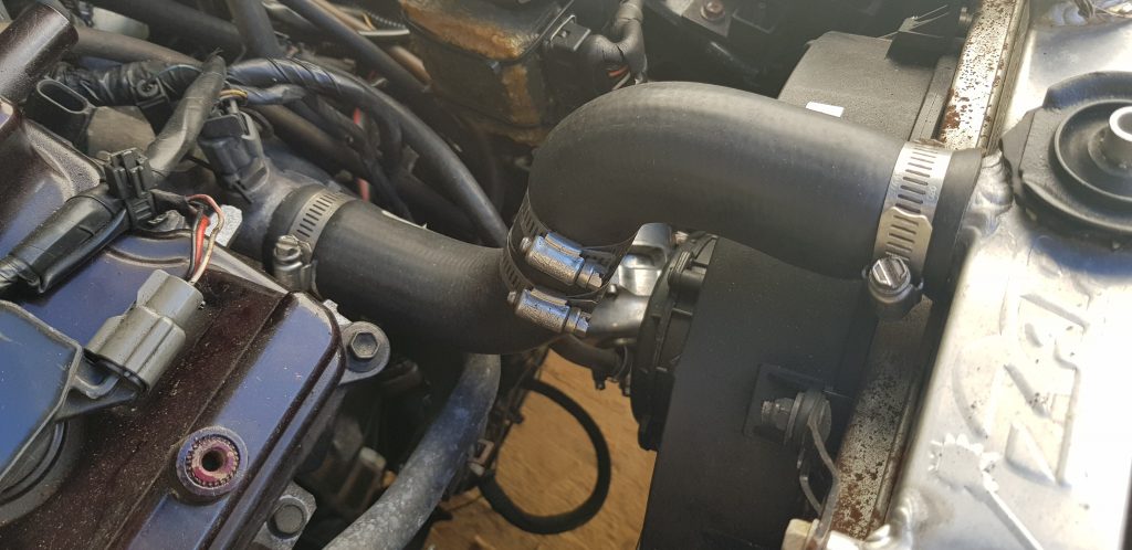
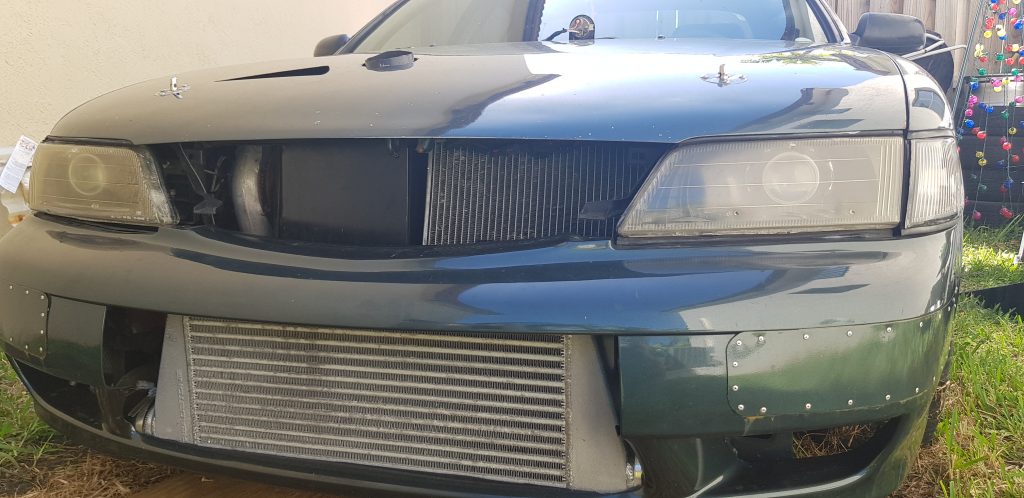
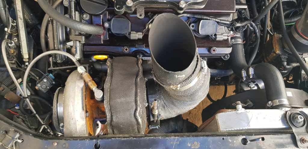
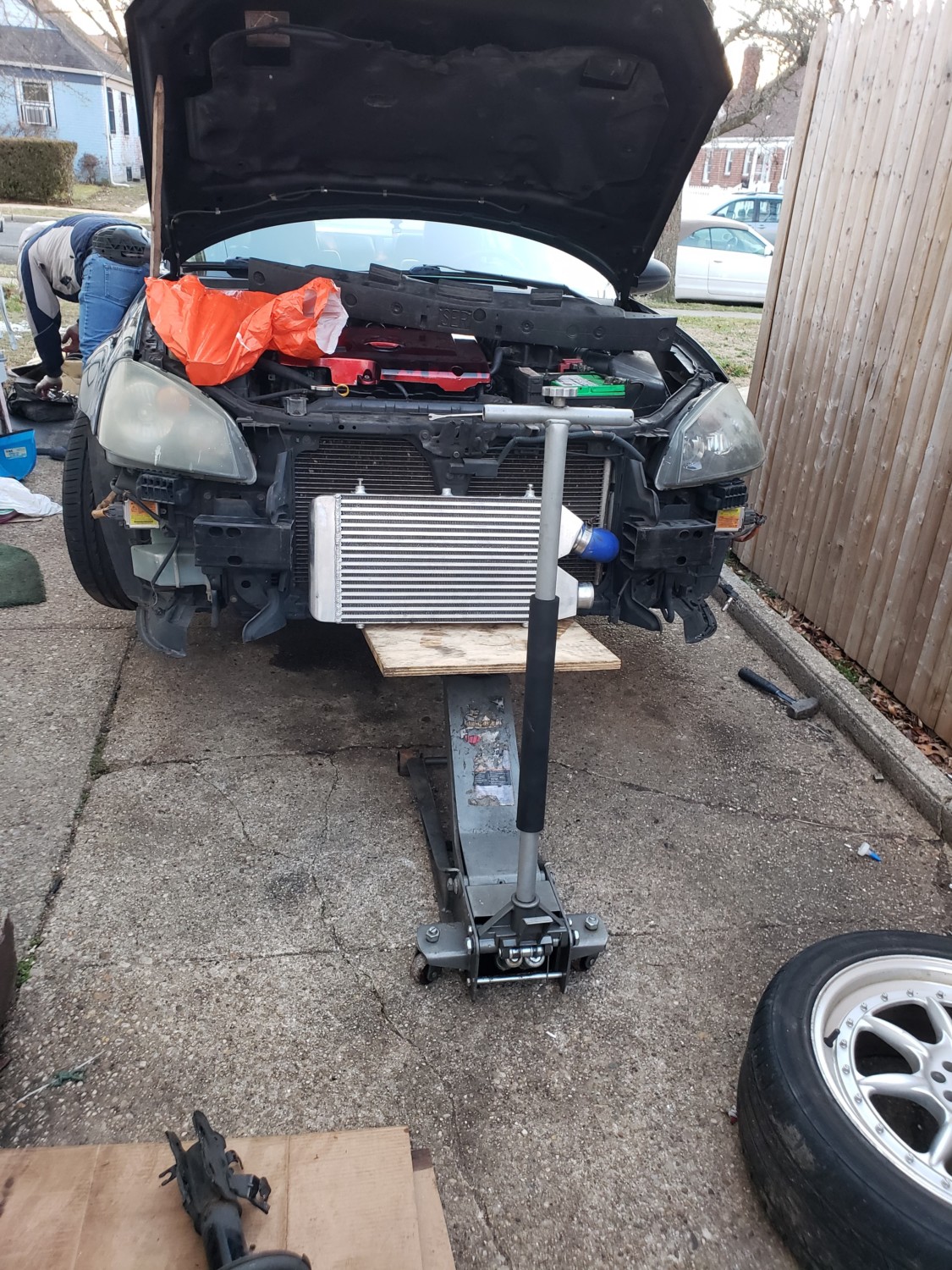
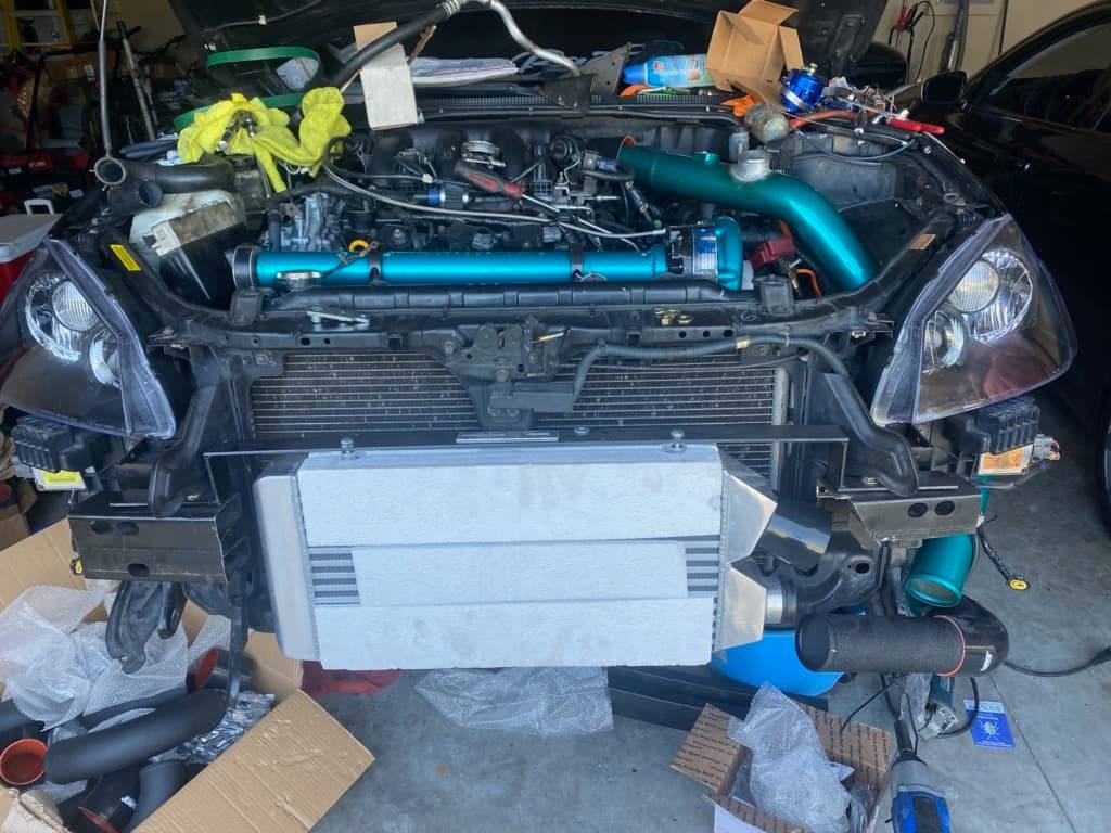
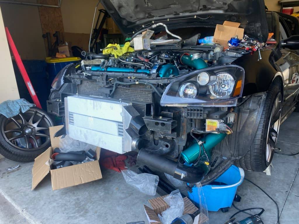
My plan was to place the turbo in the location of the AC compressor and remove the compressor. I mocked up the physical turbo to check the spacing in that area and I decided to put the turbo higher near the grill. Part of the reason for the new position was because I did not want to keep using a scavenge pump; the turbo would require one due to its low position.
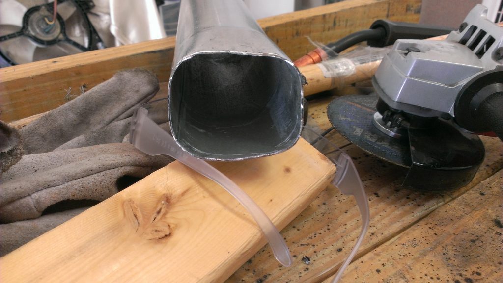
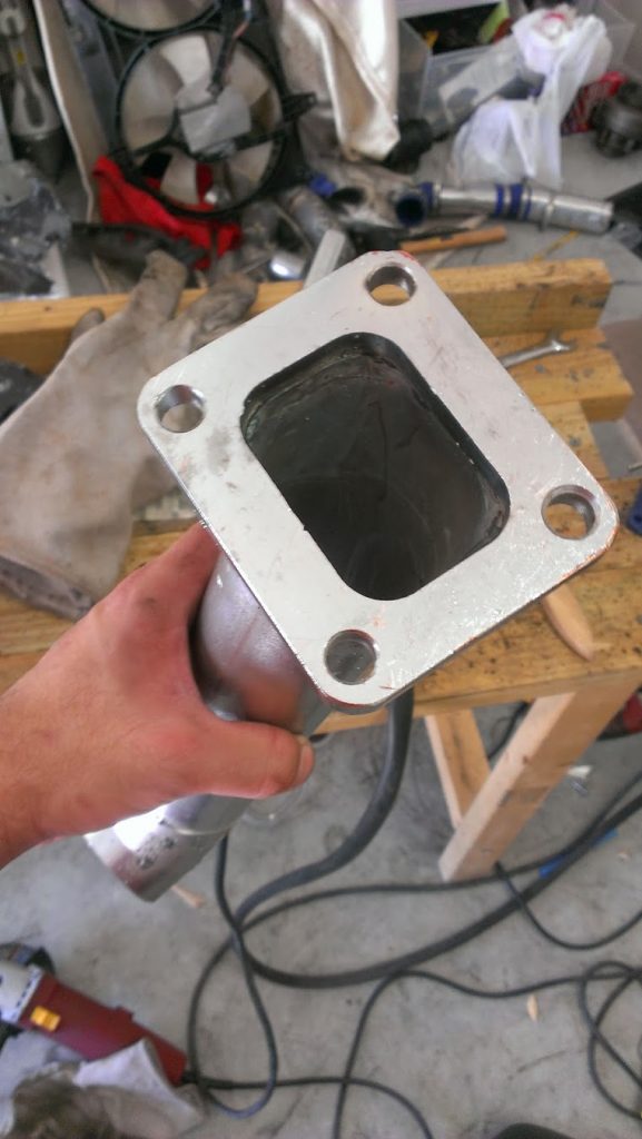
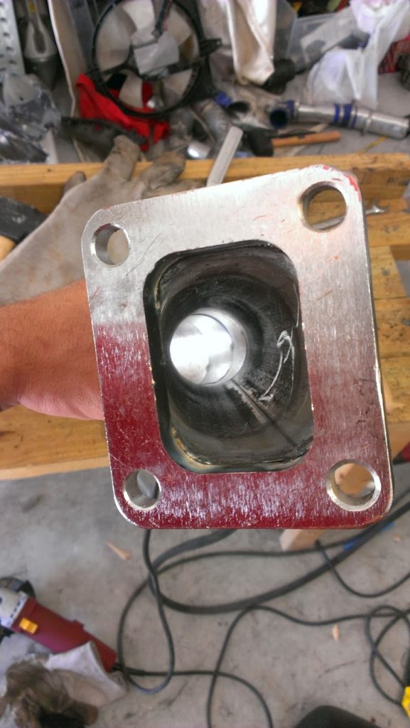
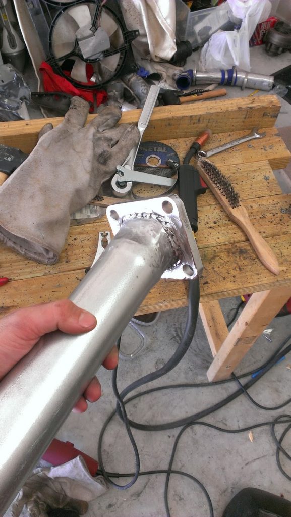
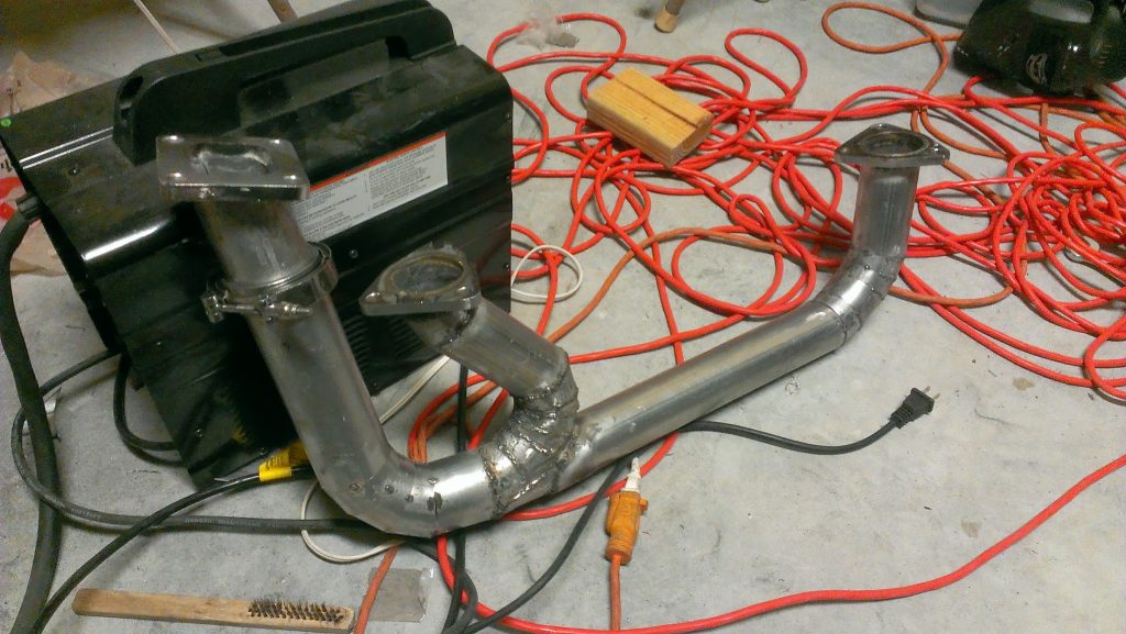
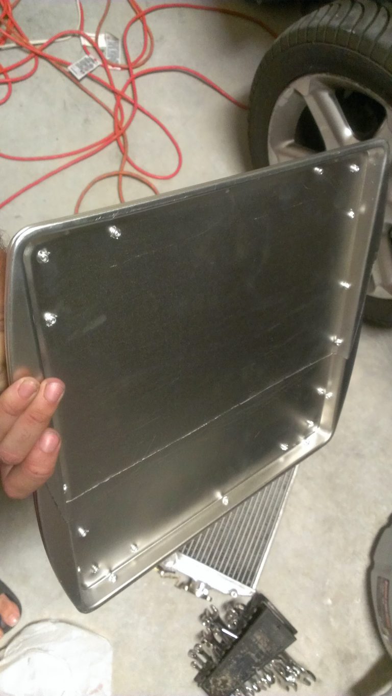
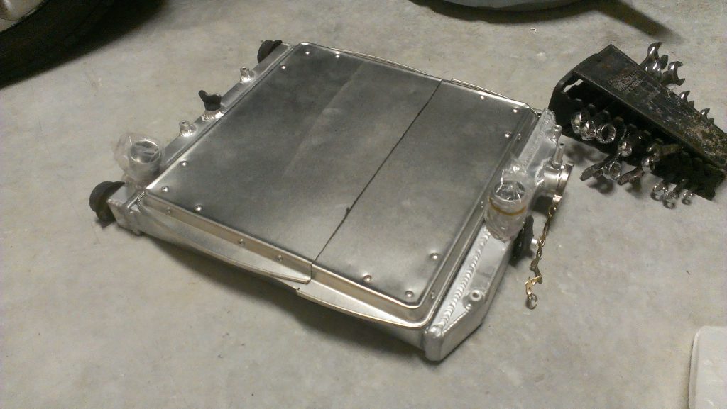
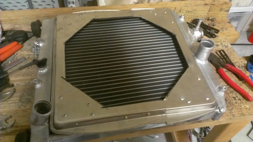
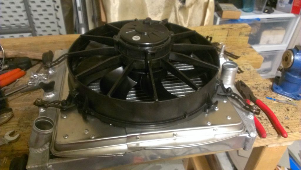
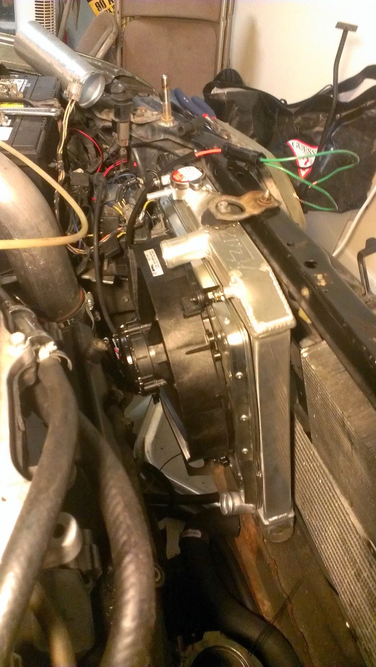
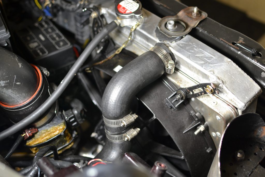
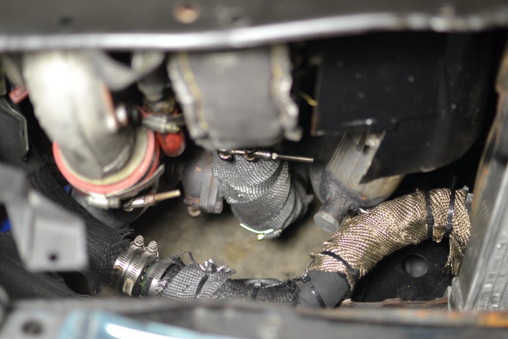
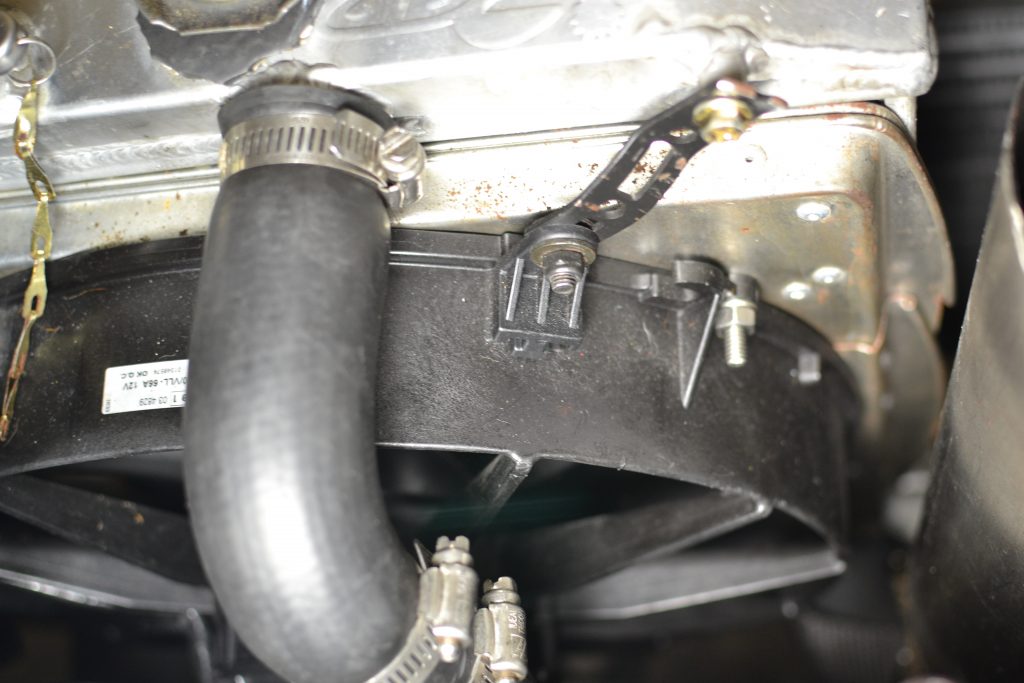
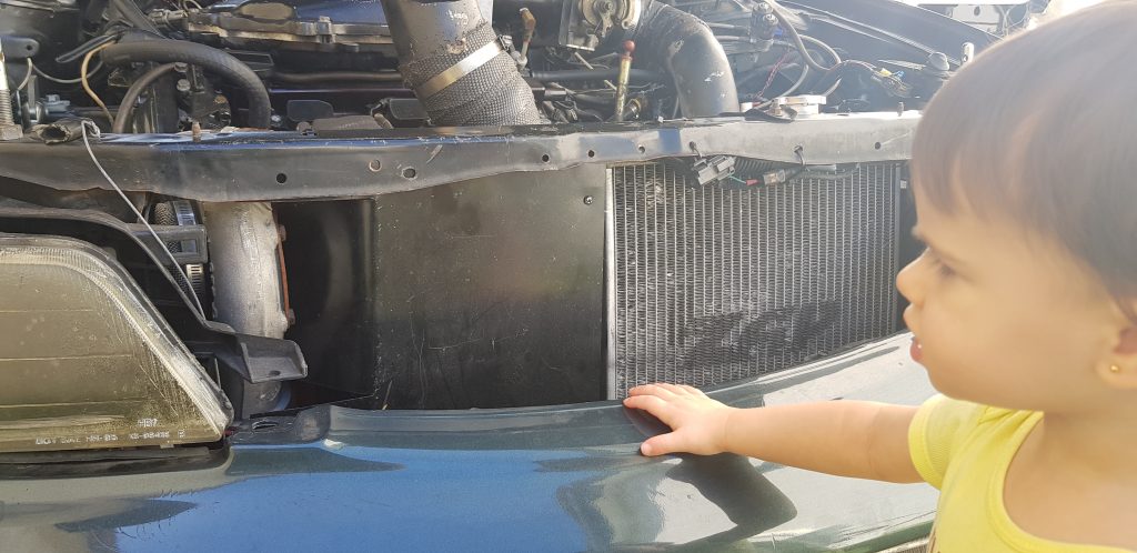
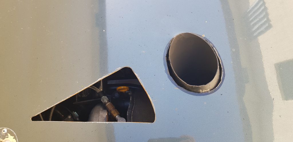
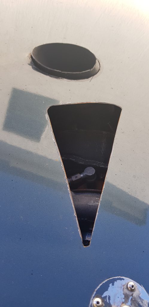
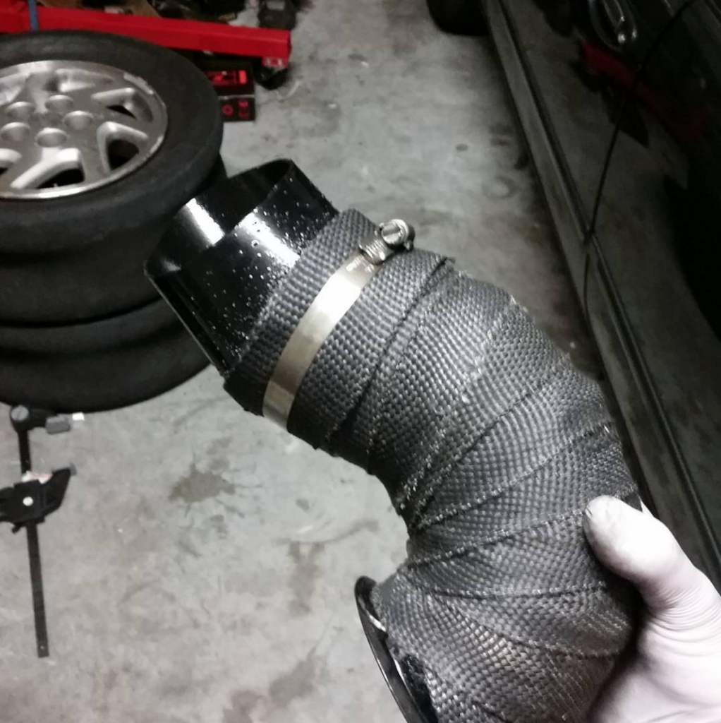
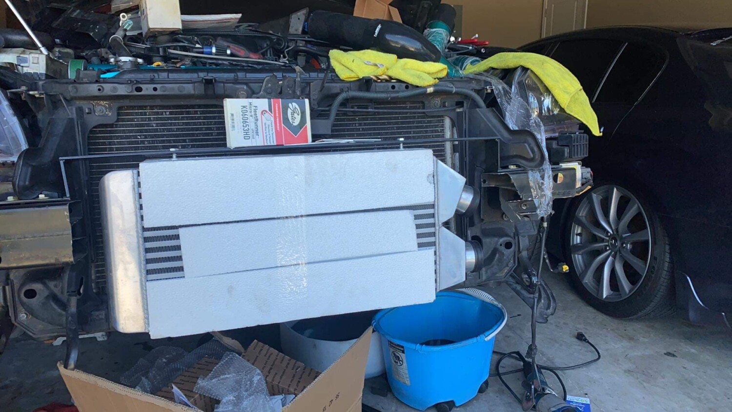
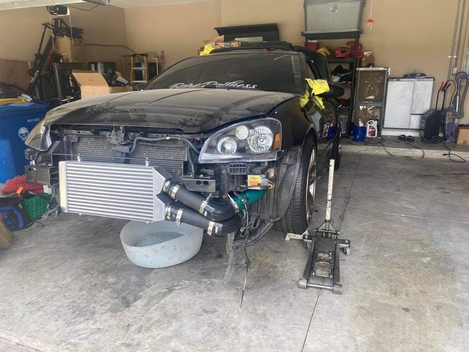
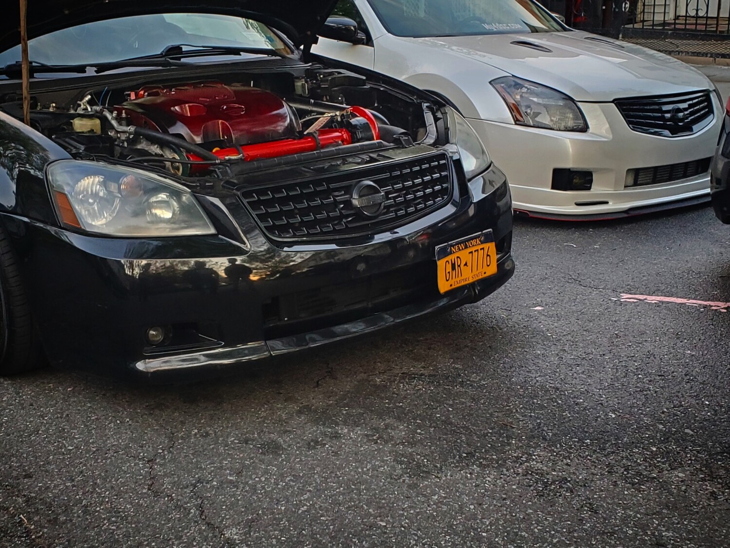
The headers were the factory iron ones, the flanges connecting to the header were reused from the Y Pipe previously used. The feed pipe has the same positioning as the Y Pipe except it aimed forward instead of the back, passing between the crossmember and the oil pan then up towards the alternator and above it. This new location required the use of a half size radiator. I used a Honda Del Sol 2 core with a custom shroud(It will be another blog entry). For the down pipe, you can see in the following pictures that I created a bend from the turbo down to the crossmember. The pipe then turns towards the back of the car and goes in parallel with the feed pipe (y pipe). After the feed pipe the downpipe continues on to the cat back like the exhaust system normally would. Here is the final location:

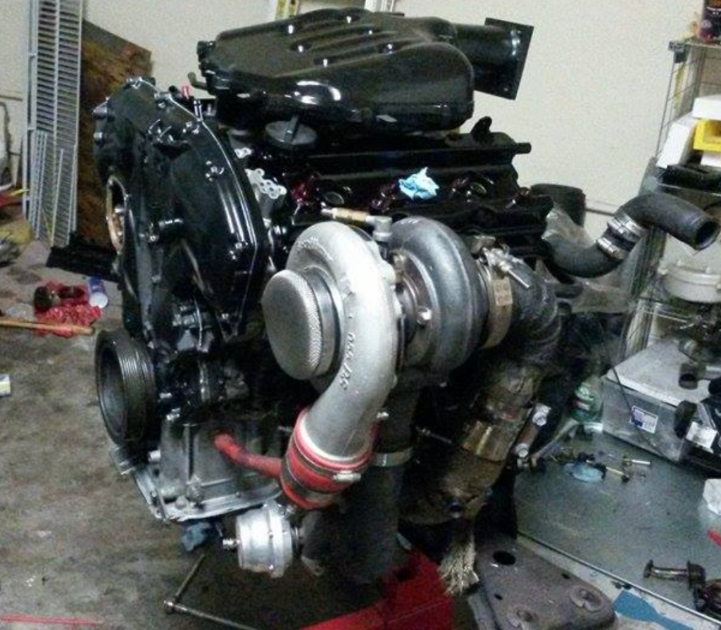


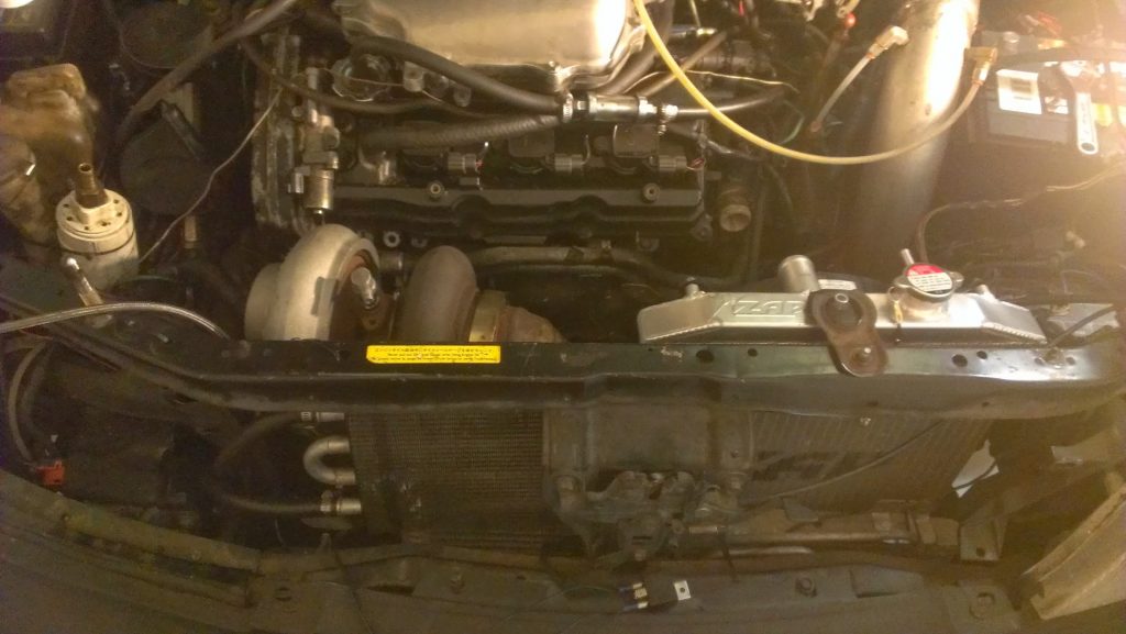
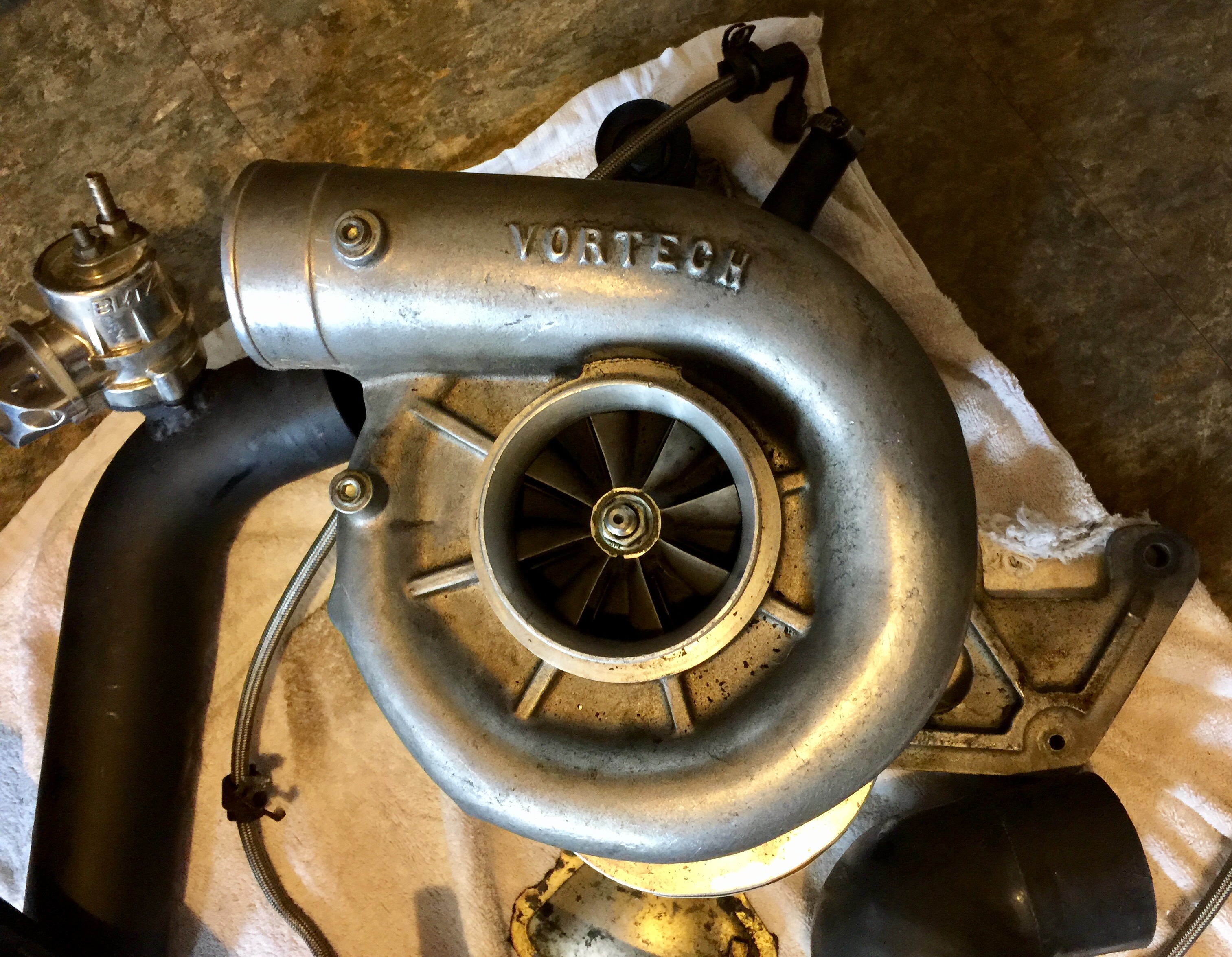
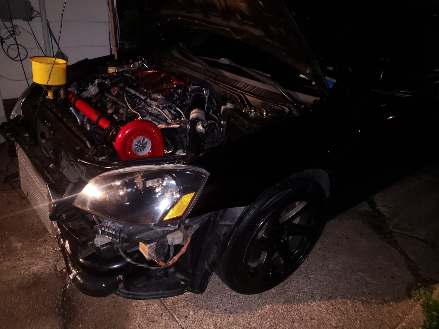
This video shows the initial engine start up after finishing the turbo kit. This was with the same turbo that was in the rear mount setup, which was an HX40Pro with a Bullseye .70AR turbine housing. This turbo’s spool up was quick as a rear mount and as a front mount with little travel it was instant.
Some of the details of this build:
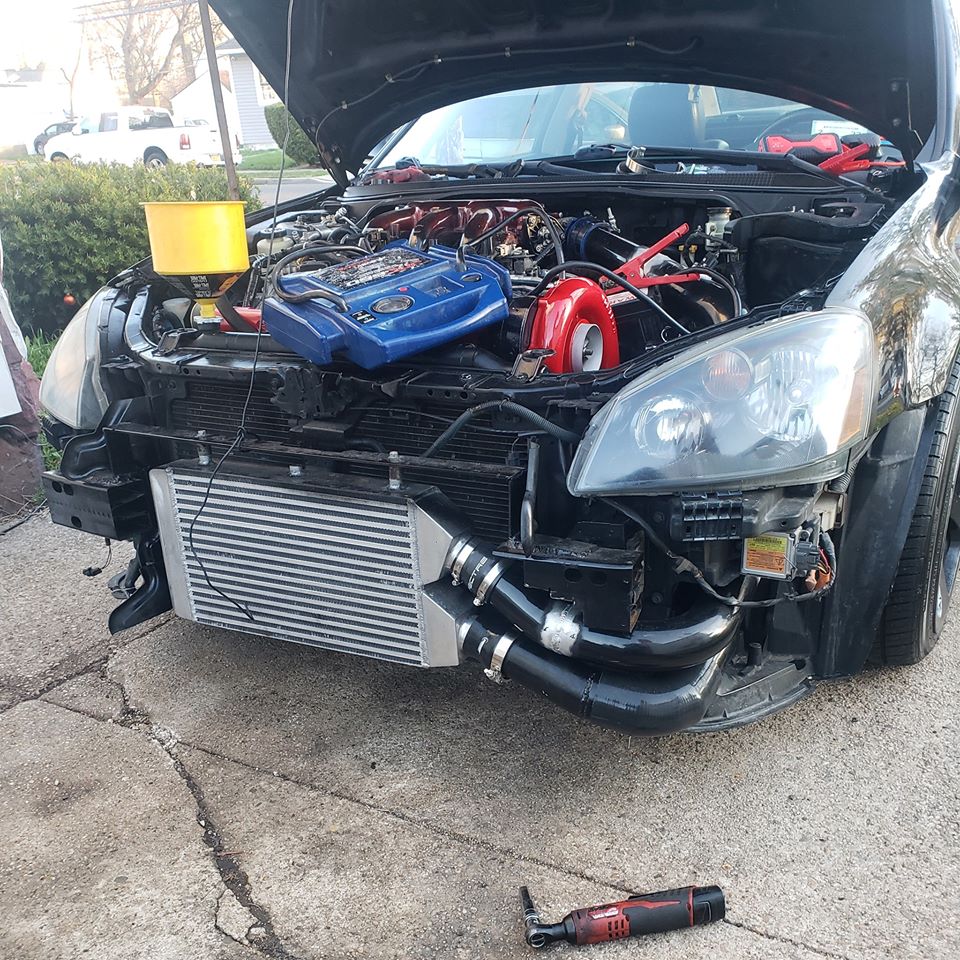
- Turbo: HX40Pro with a Bullseye .70AR
- Wastegate: Tial 38mm, open to atmosphere
- Blowoff Valve: Tial 50mm
- Injectors: ID 1000cc
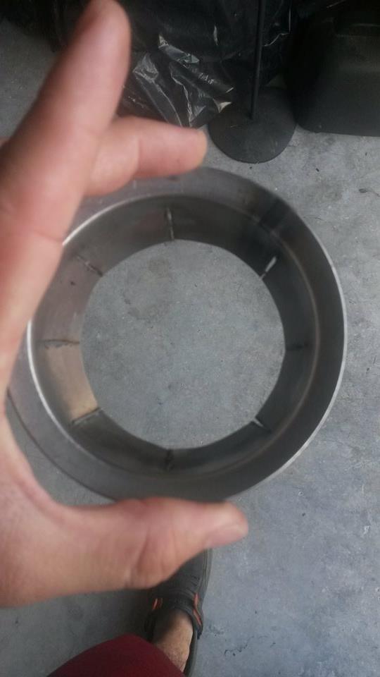
- Turbo feed pipe size has 2.25in legs coming off the headers and merging into 2.5inch up to the turbo. There is a v-band in place before the turbine to be able to swivel the turbo around.
I cannot compare between Rear Mount and Front Mount because they had different turbos, I only drove the car briefly with the HX40 before I upgraded it so I do not have data to compare. But most certainly the response time for the turbo was different; the difference between the turbo being in the very rear of the car vs. being at the front was noticeable.
In the next post ill go over the cooling aspect of the setup and how I used a small radiator.
To be continued…
![]()

")

")


")


 OEM Replacement | SAVE $$$$$")