NOTE: This thread covers remedying the timing chain rattle on 1998 and 1995 model VQ30DE engines. There are differences between those engine years that require a different approach.
If you have a 96-99 model VQ30DE, a new tensioner and gasket can be installed without removing the timing cover and replacing the guide. The tensioner can be accessed via the access panel door on the lower left side of the timing cover using a 10mm socket wrench.
Only the 95 model engine required timing cover removal to replace the guide with the updated version.
Today I performed a Timing Chain Tensioner transplant from a 99 model I30 to the 98 Maxima. The 98 Maxima had the typical morning timing chain clatter noise that comes from a worn tensioner piston inner seal and leaking valves.
The 99 I30 received a new Tensioner and Gasket sometime in 2012. This used tensioner has approximately 40,000 miles. However, this old tensioner has a gasket. I will find the gasket part number and report back more information on how to perform a quick tensioner transplant.
Meanwhile, the 98 Maxima appears to be getting along very well with the replacement tensioner. The engine runs smoothly and quietly now. Hopefully, when I start it at 5 AM tomorrow morning, the usual clatter will be gone.
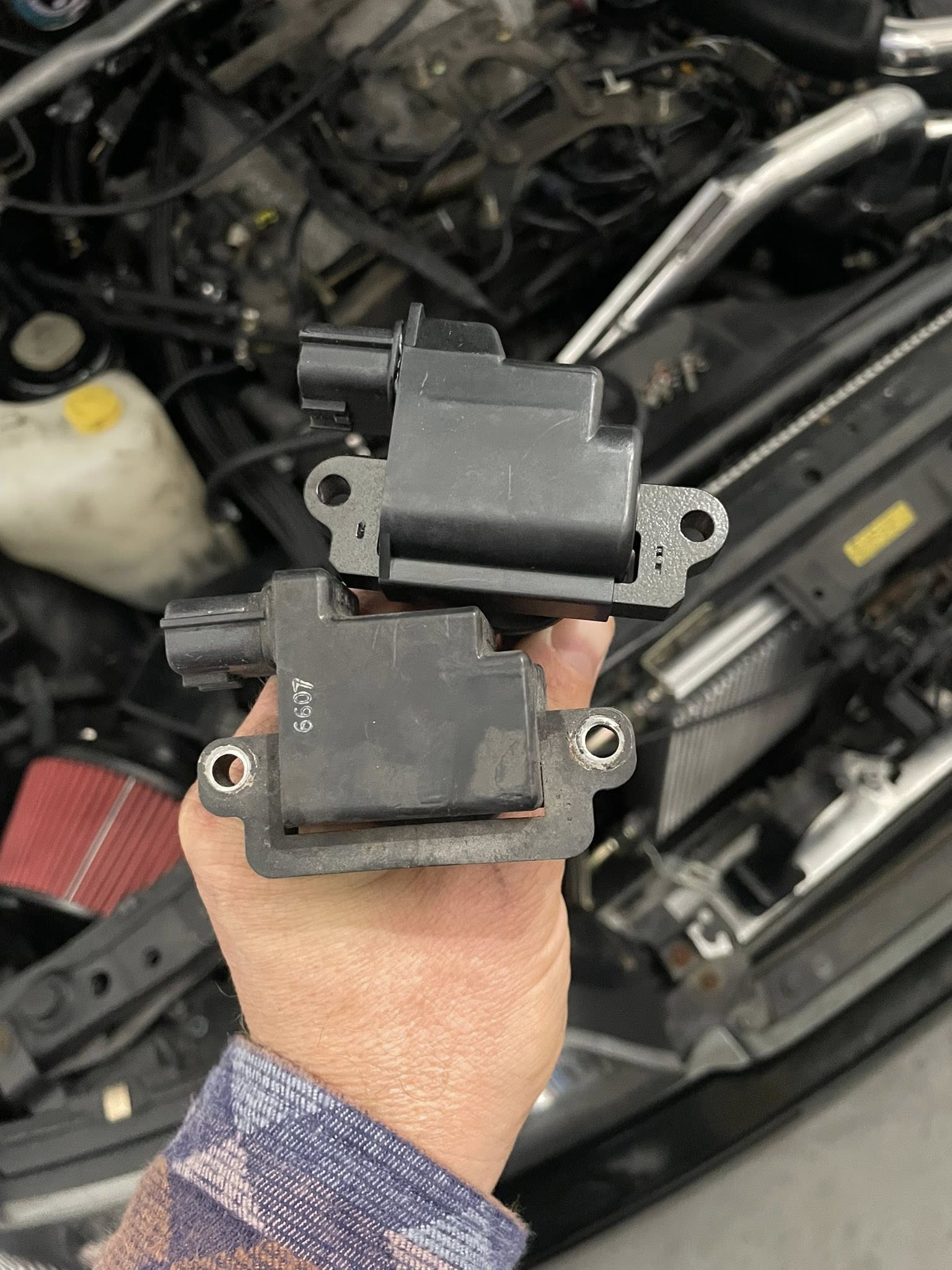
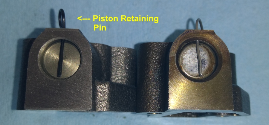
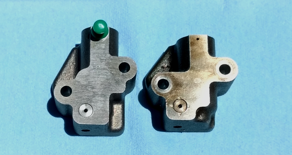
Here’s a picture of the replacement tensioner with a gasket on the left with a regular OEM tensioner from a 97 model SE “junkyard vehicle” on the right.
The results are almost unbelievable. After sitting all night, there was no morning clatter or valve train noise today at 6 AM. This must be how it sounded when it was new.
TSB Notes
Make: NISSAN Model: MAXIMA Year: 1999
Service Bulletin Number: NTB00054 Bulletin Sequence Number: 139 Date of Bulletin: 06/00
NHTSA Item Number: SB613977 Component: ENGINE: TIMING GEAR AND CHAIN Summary: VEHICLES BUILT BEFORE JN1CA31D1YT746029 MAY EXHIBIT A ENGINE TIMING CHAIN NOISE.
—————————————————————————————-
Note that I just ordered a tensioner for a 95 model with two gaskets and four bolts from CourtesyParts for the 99 models that is running a 95 model engine. The 95 models use a different tensioner.
The Tensioner I ordered for the 95 model engine is 13091-31U26 for $83.84 at CourtesyParts. The only picture I see of this part contains a guide and the tensioner. If that tensioner requires a new guide, then I’m stuck with removing the timing cover. I need to see how this 95 part is going to work before I can recommend it.
Here’s a picture below for engines built from 1/96 +.
For an I30, I see OIP has the part listed for $61.62.
This tensioner looks like the ones I’ve pulled from a 97, 98, and 99 model engine.
Somehow I think the gasket seals the drain vent to hold oil inside the chamber for long periods of time to reduce the amount of morning clatter.
—————————————————————————————-
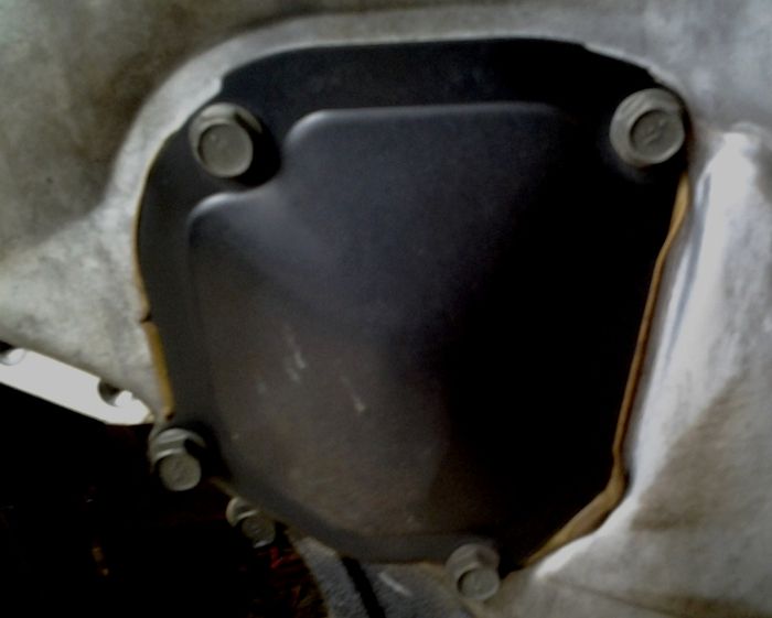
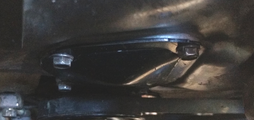
The tensioner sits behind this timing cover access panel. The access panel is held in place with four 10mm bolts.
Note: ALL bolts associated with timing chain tensioner replacement are 10mm.
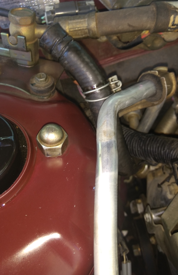
Remove the Power Steering return hose from the reservoir and loosen the A/C line bracket. The idea is to get the PS hose and A/C line out of the way to provide more room for working with the tensioner.
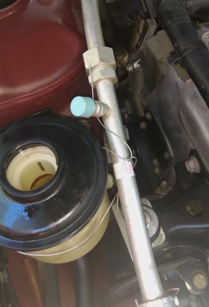
Mechanics wire came in handy to secure the A/C line to the PS fluid reservoir. You can see the tensioner cover in the lower right center of this picture.
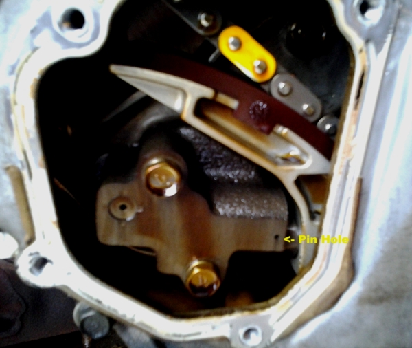
When the tensioner access panel has been removed, you can see the tensioner and the two 10mm bolts that hold it to the engine.
A close-up of the tensioner shows the piston is held in position for installation by the retaining pin. I used some mechanics wire to make a pin for an old tensioner that kept for example purposes.
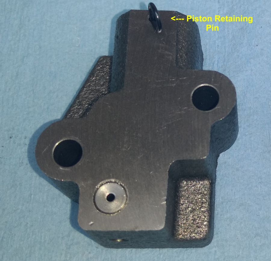
Here’s another picture of the retaining pin. The pin must be left in the tensioner until after it has been bolted down. The final step in the installation before closing the access door is to pull the retaining pin.
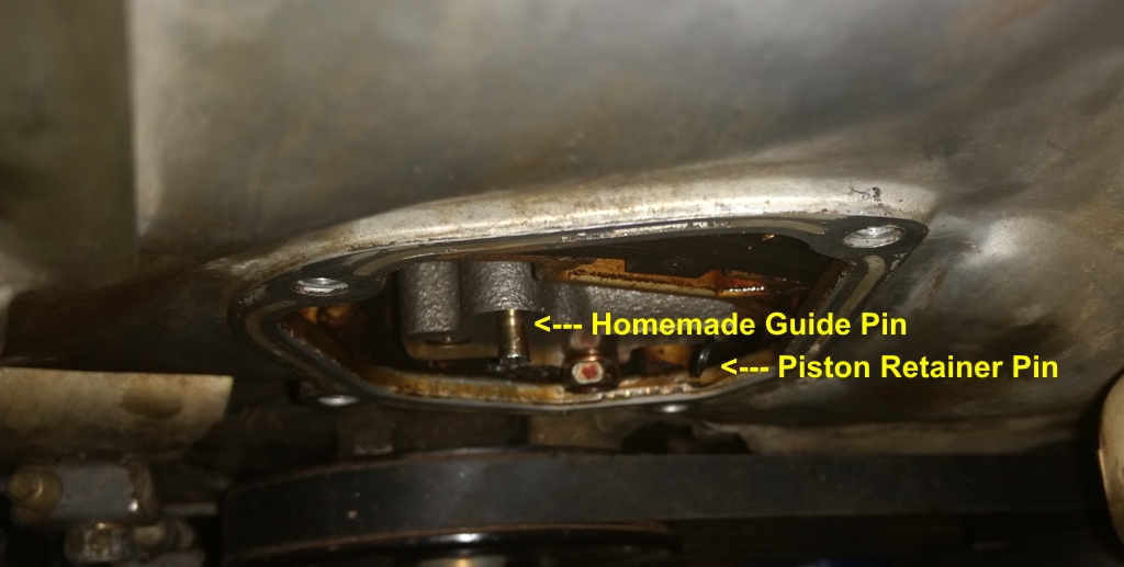
To get the tensioner to align properly over the bolt holes, I cut off the head of an extra bold to make an installation guide pin. I turned the guide pin into the block just enough for me to hang the tensioner on it to get the lower bolt started. Once I had the lower bolt started, I removed the guide pin and installed the upper bolt.
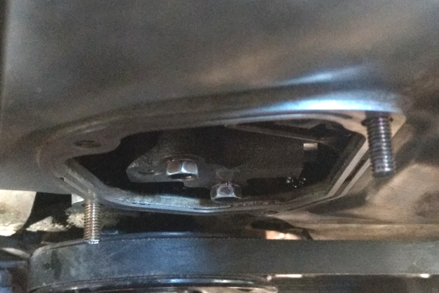
To get the access door properly aligned over the timing cover when the edge was covered in RTV, I used some extra 10mm bolts and made two additional guide pins. Once the access door was in position, I installed two cover bolts, then removed the guide pins and finished installing the remaining two bolts.
Here’s a picture of the access door at the end of the operation. You can see that I used Permatex Ultra Grey RTV.
————–
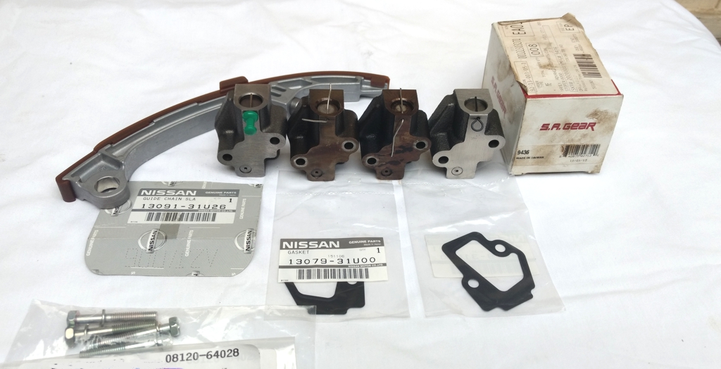
The parts arrived from Courtesy Nissan today. Now that was a Nissan Fast order. It looks like I have everything I need to work on the 99 models (with the 95 engine) this weekend.
So I purchased the tensioner for a 95 model that comes with a guide. I really do not want to use the guide. It was just over 3 years ago that I had the timing cover off of that engine and examined the guides. That engine only had 82,000 miles at the time. I will get a mileage reading this weekend when the car returns. That engine easily has under 150,000 miles.
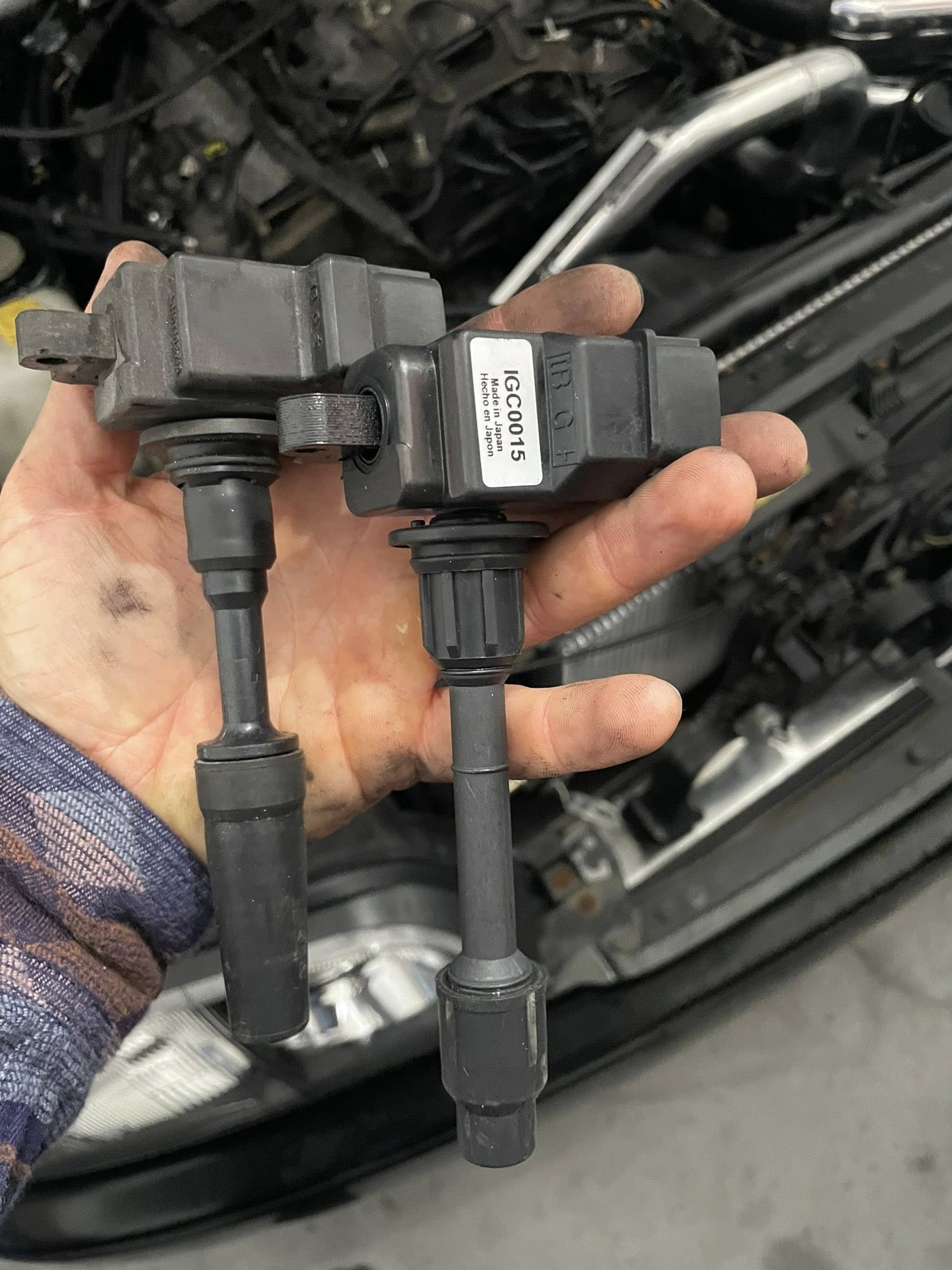
The new OEM tensioner is on the left. The two tensioners in the middle are from a 97 (salvage yard car) and the 98 models. The tensioner on the right is an SA Gear that I purchased over 3 years ago to go in the 99 models. The guy that did the engine installation and changed the water pump did not install it. While it looks like the OEM, it doesn’t have the same tight/precise feel as the OEM. I can tell the OEM has been built to some very exacting standards. So I don’t know if I will ever use the SA Gear guide.
The gaskets are the right parts exactly. The bolts are correct. I ordered an extra set of bolts and gaskets. I suspect the secret to success here is to always include the OEM gasket with a new tensioner.
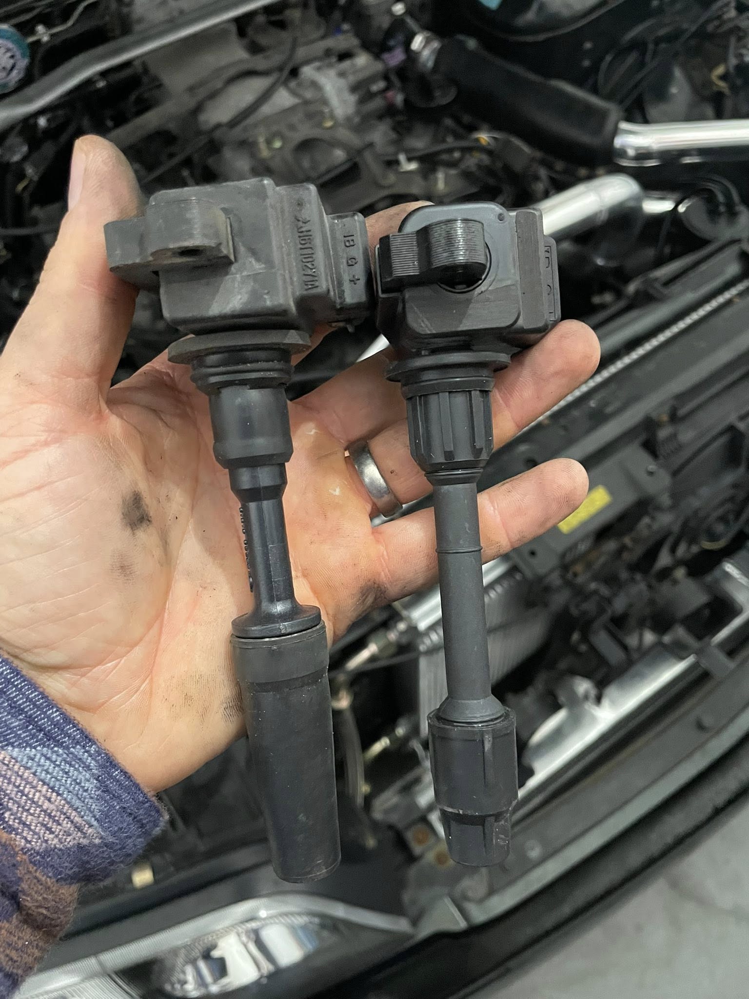
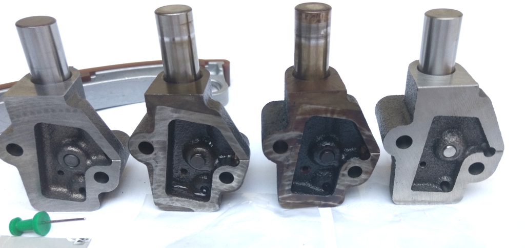
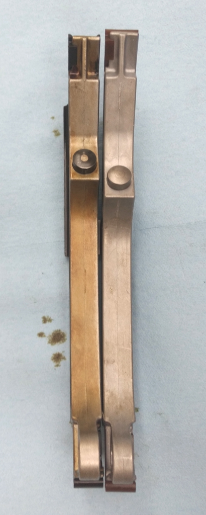
Here’s a close-up of the tensioner back sides below. Again the new OEM is on the left with the SA Gear on the right.
The piston on the new OEM has a very tight and precise fit. There is no piston wobble or shake with the new OEM part. I sure hope I can use it on the 95 model engine.
The SA Gear part (far right) is listed for 95-04 models with both 3.0 and 3.5 engines. I call the SA Gear part a “generic aftermarket” tensioner.
Here’s a video of the 99 Model (95 Engine) before the new tensioner. Yeah it sounds like a diesel in the morning.
The 98 sounded like this before the tensioner upgrade.
Here’s a video of the 98 model after the new tensioner and gasket installation. The 99 model will sound like then when I finish the upgrade. This engine has approximately 237,000 miles.
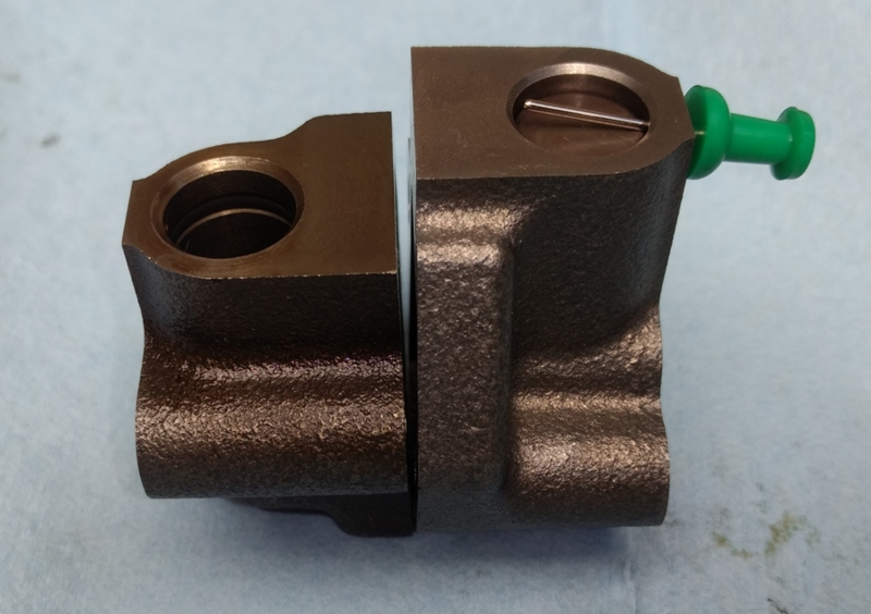
Here’s a picture of the old 95 model tensioner (left) compared to the new (right). I like the new design.
Here’s picture with the new tensioner on the left and the old on the right.
Side-by-side comparison of old 95 model guide compared to the new replacement.
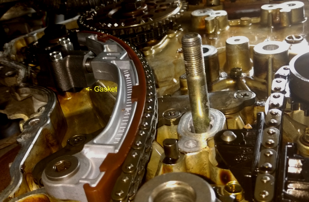
The new tensioner, bolts, gasket, and guide installed.
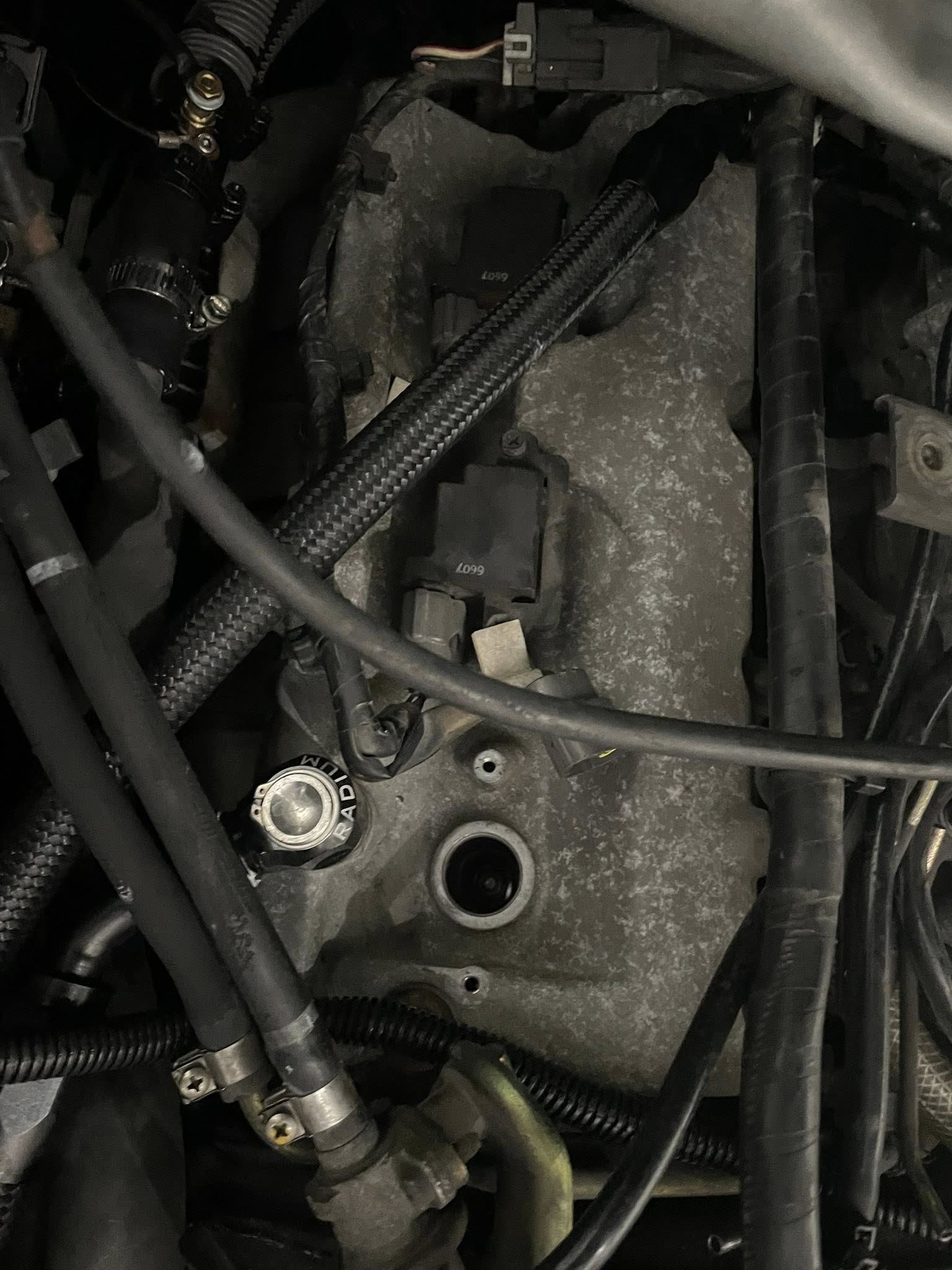
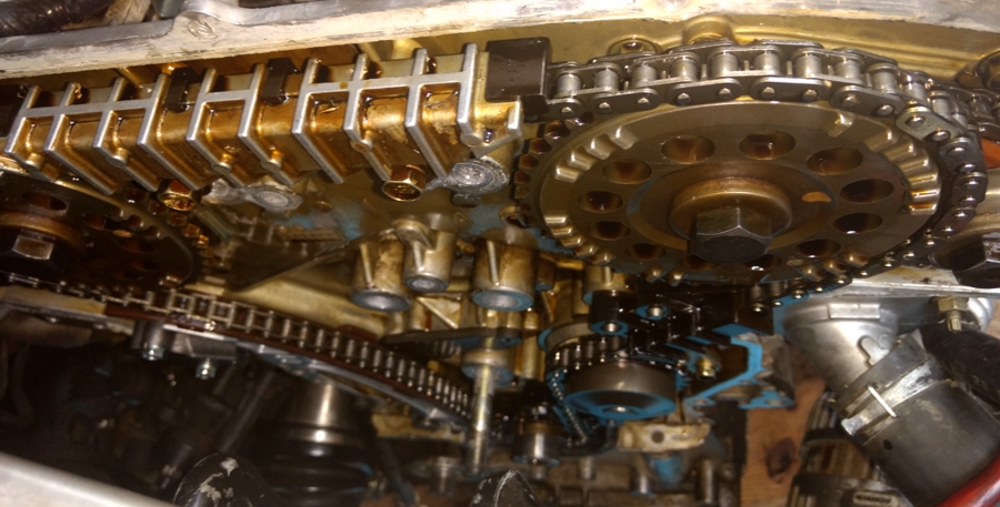
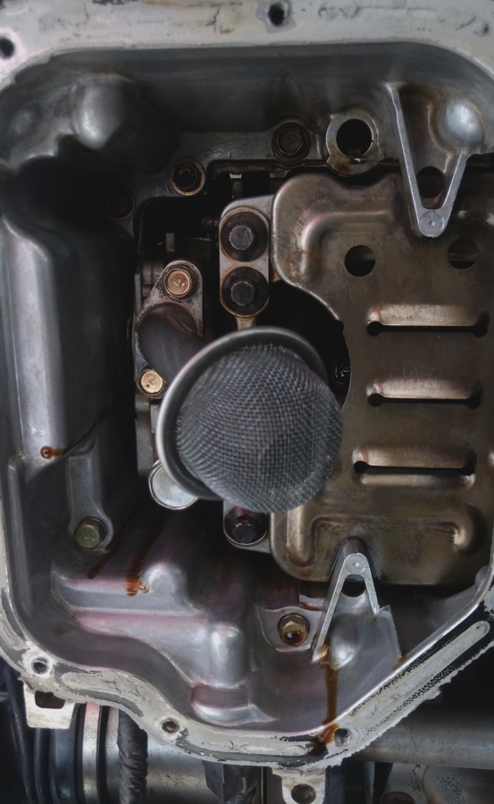
Based on the chain health from the picture below, I think the chain and engine will outlast the rest of the car.
The car (body) now has over 210,000 miles. It looks like a low wear engine.
No oil sludge in the upper oil pan parts.
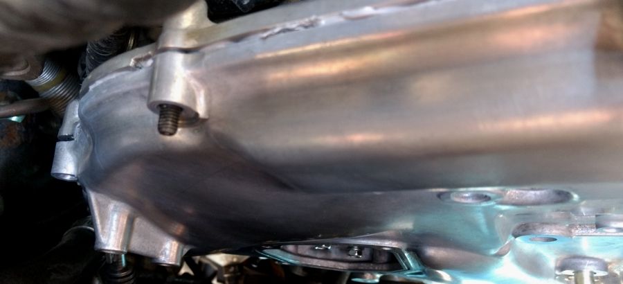
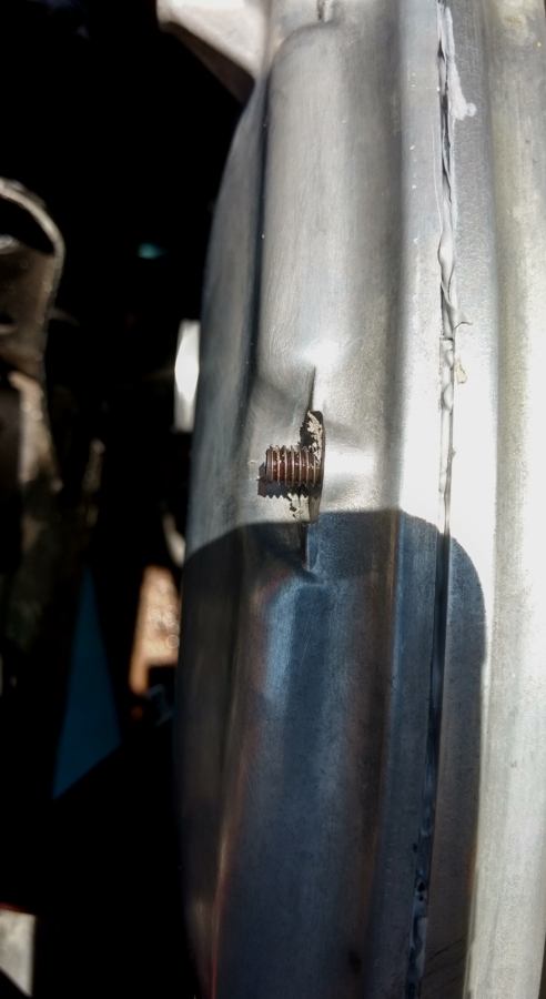
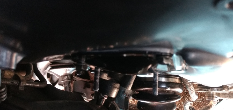
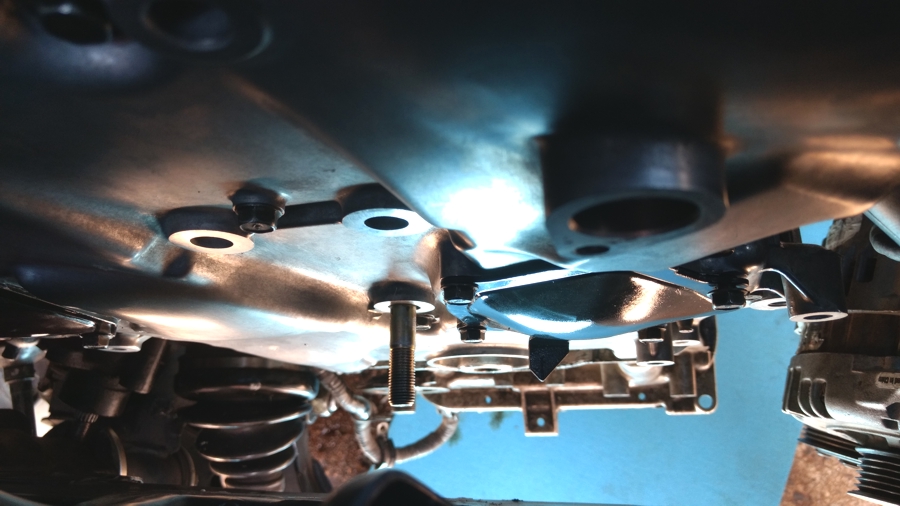
I used the M6 -1.00 x 31 mm automotive stud bolts from Ace Hardware as guide pins to hang the Timing Cover and access doors today. Here’s some pictures from today’s work below.
Another picture of using a stud bolt as a guide pin to hang the timing cover.
Removed the stud bolts and then used the regular 10 mm TC bolts.
Using stud bolts as guide pins for installing the access doors.
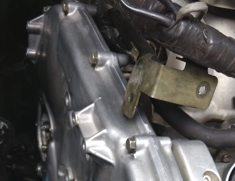
Here’s a picture of the water pump access door after installation. Note that I did not completely remove the alternator or A/C compressor for this operation. I used some wire to suspend the compressor so it would not dangle by the hoses. The alternator is resting on the compressor.
The upper oil pan has been released but not completely removed in this picture. I reinstalled the passenger side engine mount so the engine would be held up by at least two engine mounts before I removed the center cross-member to remove the upper oil pan.
Started the engine this evening. After the expected new tensioner noises that sound like a train clattering down the tracks, all chain and valve system noises stopped. You’ve got to hold the RPM at 2,500 for about 10 minutes after the initial warm up to let the oil circulate through the tensioner system for the system to get quiet. This is a very different running and sounding engine now.
I will make a “cold start” video tomorrow morning and upload it to youtube.
I can’t recall having a 4th gen without some amount of clatter. It almost seems weird.
Here’s the before and after videos from the 99 (95 model engine) so show the difference made by replacing the tensioner, guide, and using the gasket as recommended in the TSB.
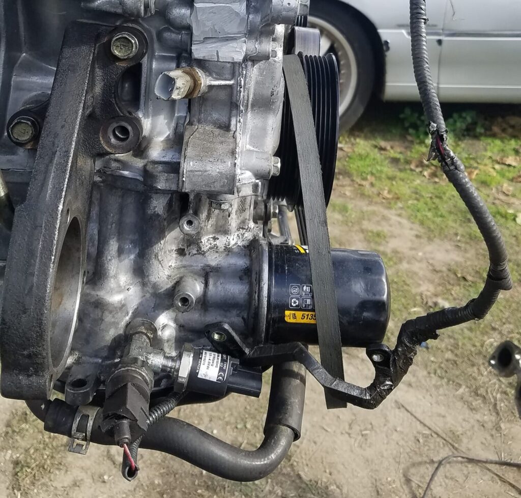
You may get one of the Nissan vehicles listed below in the shop with engine oil accumulated on the engine block below the engine oil cooler area. Inspect the engine, engine oil cooler and the oil cooler gasket for oil leakage. You may use a fluorescent oil dye leak detector to help more easily determine which component is leaking. If the oil is leaking from the oil cooler rubber gasket, replace the rubber gasket using the following manufacturer’s Service Procedure ….
You may get one of the Nissan vehicles listed below in the shop with engine oil accumulated on the engine block below the engine oil cooler area.
Inspect the engine, engine oil cooler and the oil cooler gasket for oil leakage. You may use a fluorescent oil dye leak detector to help more easily determine which component is leaking. If the oil is leaking from the oil cooler rubber gasket, replace the rubber gasket using the following manufacturer’s Service Procedure.
Vehicles:
2004-2006 Quest
2000-2006 Maxima
2003-2006 Murano
2002-2006 Altima with VQ35 engine only
Service Procedure:
Drain engine oil.
Drain engine coolant. Do not spill coolant on the drive belt.
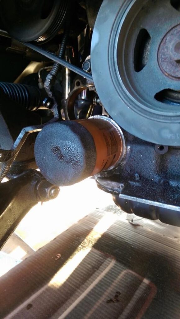
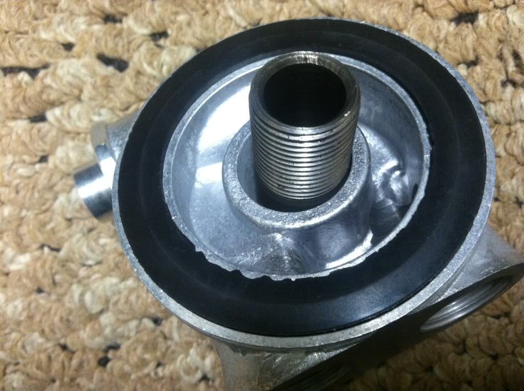
Remove the oil filter and the oil cooler.
Check oil cooler for cracks.
Check oil cooler for clogging by blowing through coolant inlet. If necessary, replace oil cooler assembly.
Inspect the oil pressure relief valve for movement, cracks and breaks by pushing the ball. If replacement is necessary, remove valve by prying it out with a suitable tool. Install a new valve in place by tapping it.
Installation is in reverse order of removal.
When installing the oil cooler, install a new rubber gasket and align the oil cooler stopper with the stopper of the oil pan.
Start engine and check there are no leaks of engine oil or coolant.
Reference:
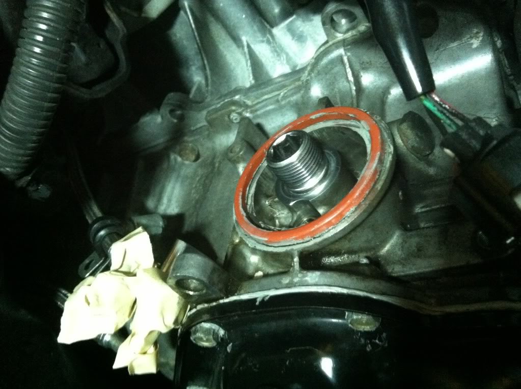
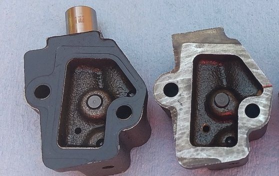
Posting this up just to clarify the relief valve part number and identification, the FSM is pretty vague.The O Ring part number OEM 21304-JA11A or Dorman part 917-036 (Dorman come 3 in a box and can get it at any parts store)
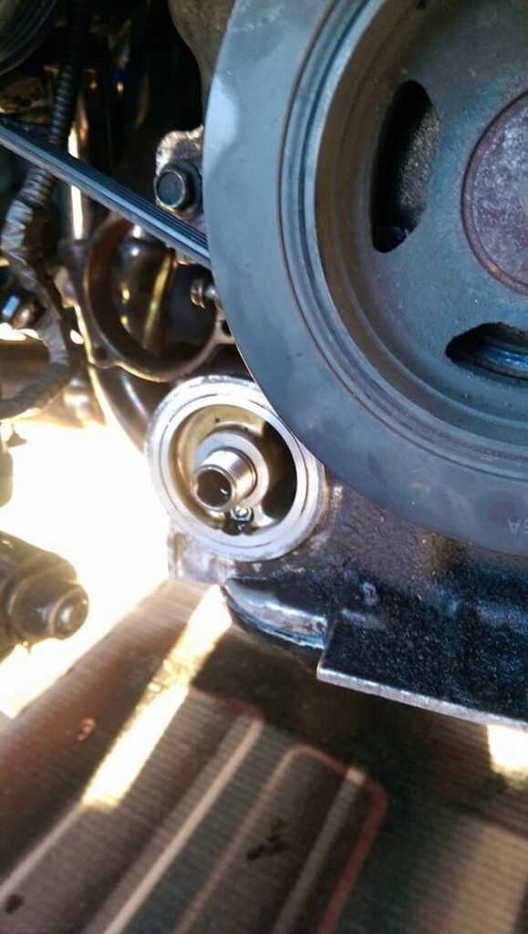
My problem was I also had a broken relief valve? One man show here, pretty tough holding the camera and trying to hold that bearing in place.
Part Number for relief valve 15241-43UOA, you can see the broken one on the left I stretched the spring trying to unseat it. You can also see half of the ridge that retains the spring and ball bearing which cracked off. Over tightening the oil filter, metal fatigue(200K) ? It comes assembled in the new relief valve.
—
Just wanted to thank you for posting this fix for the oil cooler on a G35. The part numbers were a huge help as it is often not available and you waist lots of time trying to get them. Removing the oil pressure relief valve required some thinking in order not to scratch the mating surfaces of the oil cooler itself.
I found a bolt with course threads that would actually start threading itself inside the ball bearing side of the valve. Once I had made about 2 turns of the bolt and knew it was securely inside the valve, I place a crescent wrench behind the head of the bolt and closed the jaws of the crescent wrench. I gave the wrench a few taps and the valve came out very easily and without and damage to the surface of the oil cooler.
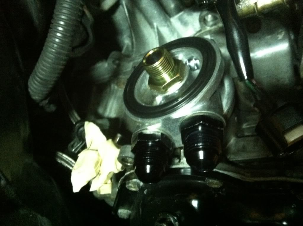
I aligned the new valve correctly and used a 6 or 8 mm deep well socket to tap the new valve back in to place until it bottomed out. I cleaned both mating surfaces well and installed the new o-ring with fresh clean oil on it in order to make sufficent contact. I installed the oil filter bolt with 36 lbs of ft, torque and installed a new oil filter.
It could not have been a better out come. I saved lots and lots of $$ and my car has not leaked another drop of oil. I have always been one to over tighten and years of changing the oil and filter caused this oil leak without a doubt. Never again will I go past 2/3 or 3/4 turn after contact again.
This setup replaces the factory oil cooler/warmer. The factory oil cooler/warmer warms up your oil and maintains it at coolant temperature. This cooler / warmer often leaks, or can not be reused due to damage or contamination. When using this delete kit vehicles must be driven carefully, with no high rpm driving until oil temperature warms up.
Parts Needed:
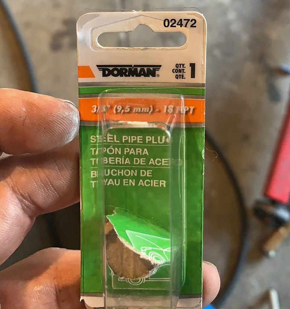
Block plug
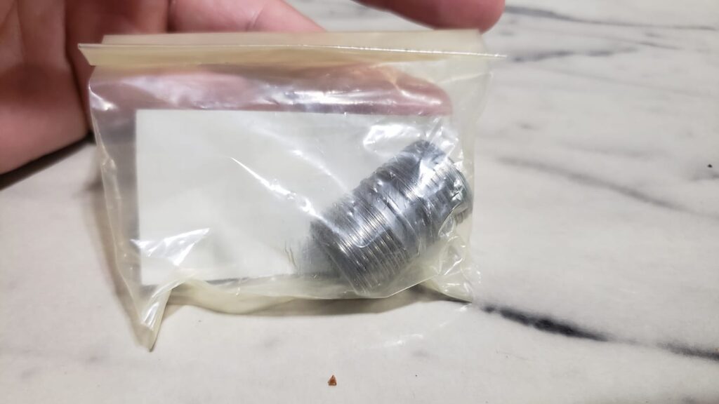
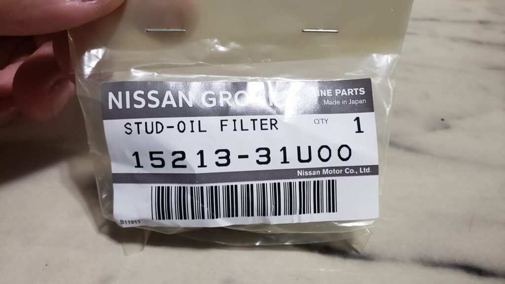
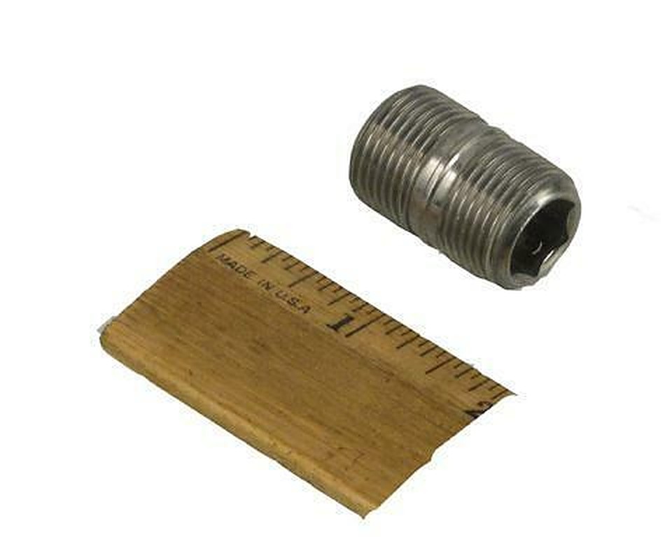
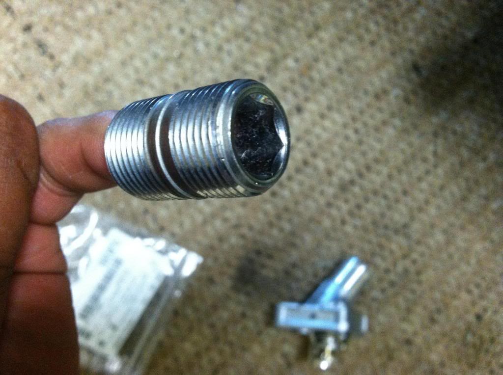
Oil filter stud Part Number: 15213-31U00
Thermostat (without coolant hose fitting)
Gasket
Advantages:
Cleans up the engine bay a lot
Gives you a clean place to put an external cooler sandwich
No worries about it containing debris. They are just bad news for highly modified cars. Many engine builders will tell you to just replace that cooler every time you build your engine because it gets so clogged up with debris and they are impossible to totally clean.
Disadvantages:
None
Part Number:
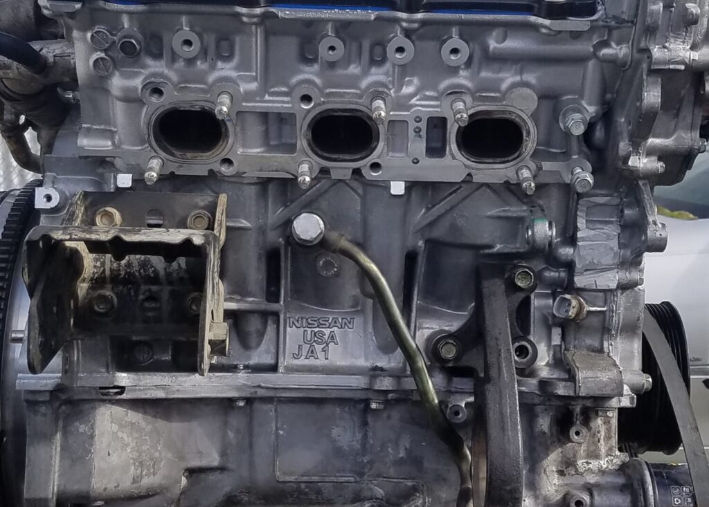
I’ve never heard of a Vq35HR having an oil cooler/warmer. Here are a couple of pics I took:
Stock VQ35DE stud
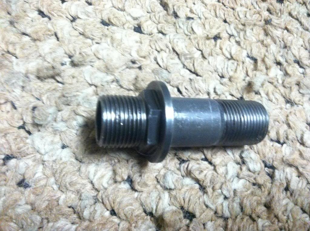
The reason why you need the VQ35HR oil filter stud. The shank is way too thin to use with an oil filter block and too long to use with just a filter.
The VQ35HR filter stud
VQ35HR filter stud installed on a VQ35DE. You can see why you will need it.
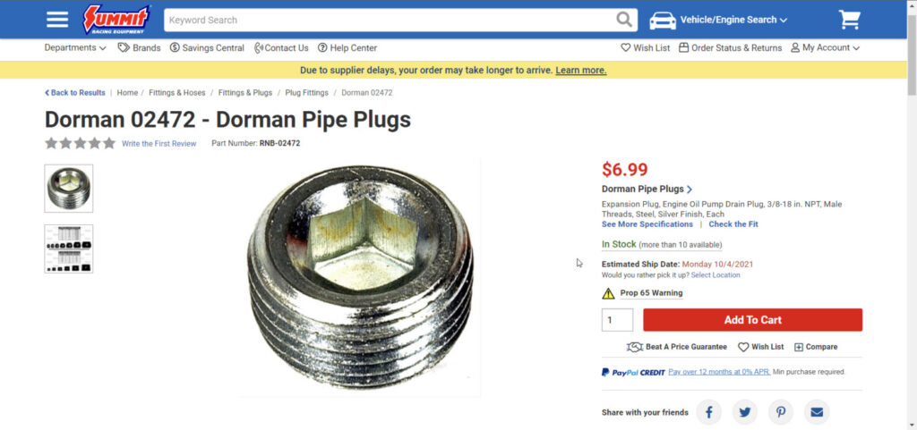
3/8BSPT threads not NPT
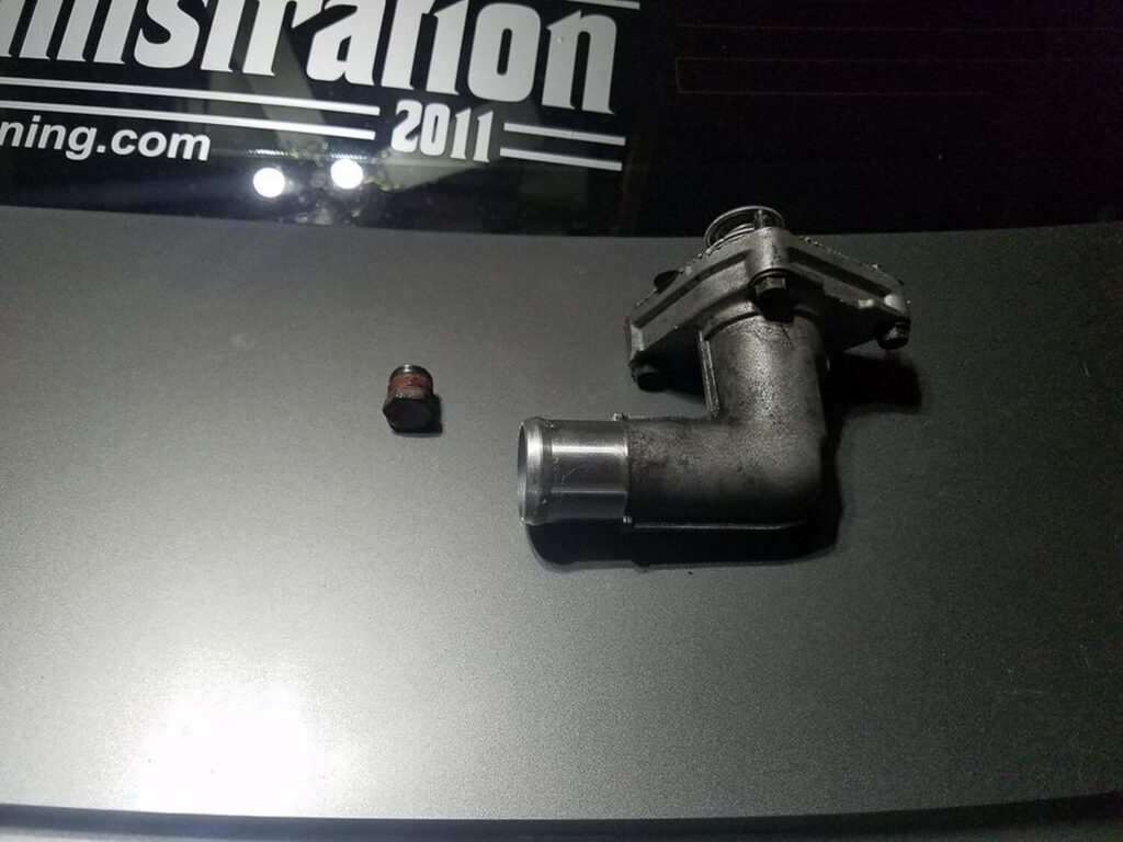
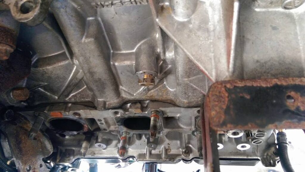
For those of you that are deleting your oil cooler. You can also get one from a 3.0 as it comes plugged.
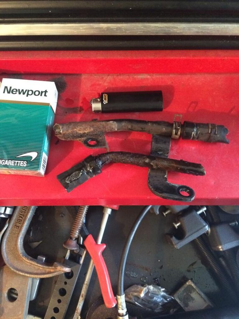
That’s the plug for the rear pipe that goes to the oil cooler.
In this post I will go over the process I went through when building my turbo kit. As many know, the car was first equipped with a rear mount turbo for many years.
Some information about the car:
1997 Maxima
Automatic
Turbo (initially rear mount turbo)
Rear Mount Turbo Preview
As a rear mount turbo, it was a great experience. It was my first time being in a turbo car much less driving one. I saw an episode of Powerblock on SpikeTV showing an installation of a rear mount twin turbo setup on a Corvette. Right away I started brainstorming and realized how easy it would be to do it. I started gathering parts and in a weekend we installed it. I went for my first drive, felt what it was like to get anything greater than 0psi and boy was I hooked. I will make a post soon about the details involved with the rear mount turbo.
I used 370CC injectors to begin with.
The turbo was a T04b with a .60ar T4 turbine.
None Intercooled with Meth.
7-10psi
Rear Mount Turbo Dyno VQ30-00VI
(Expect a post about the rear mount soon)
It made 299whp / 291wtq
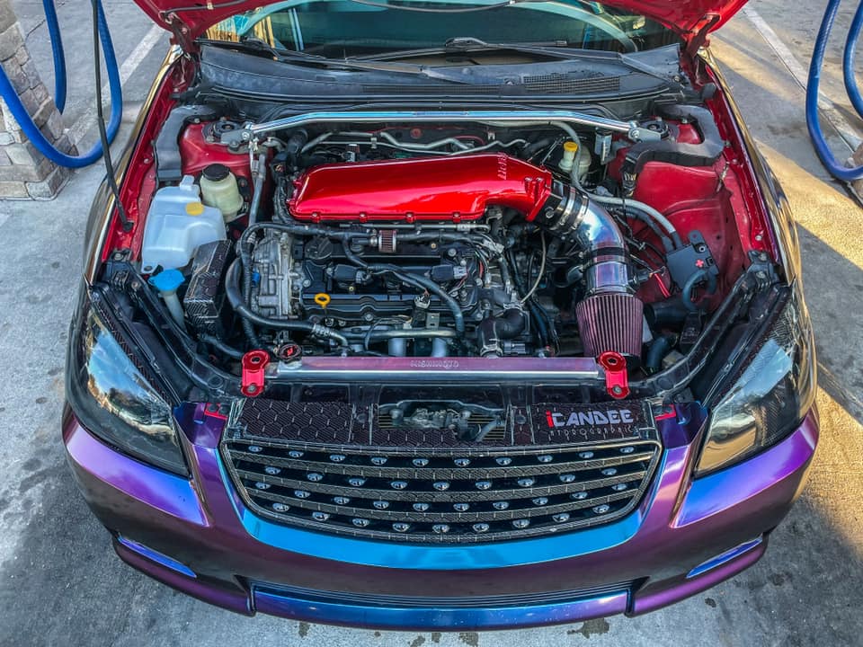
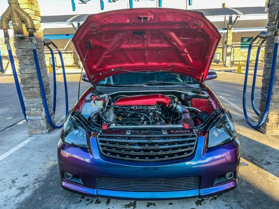
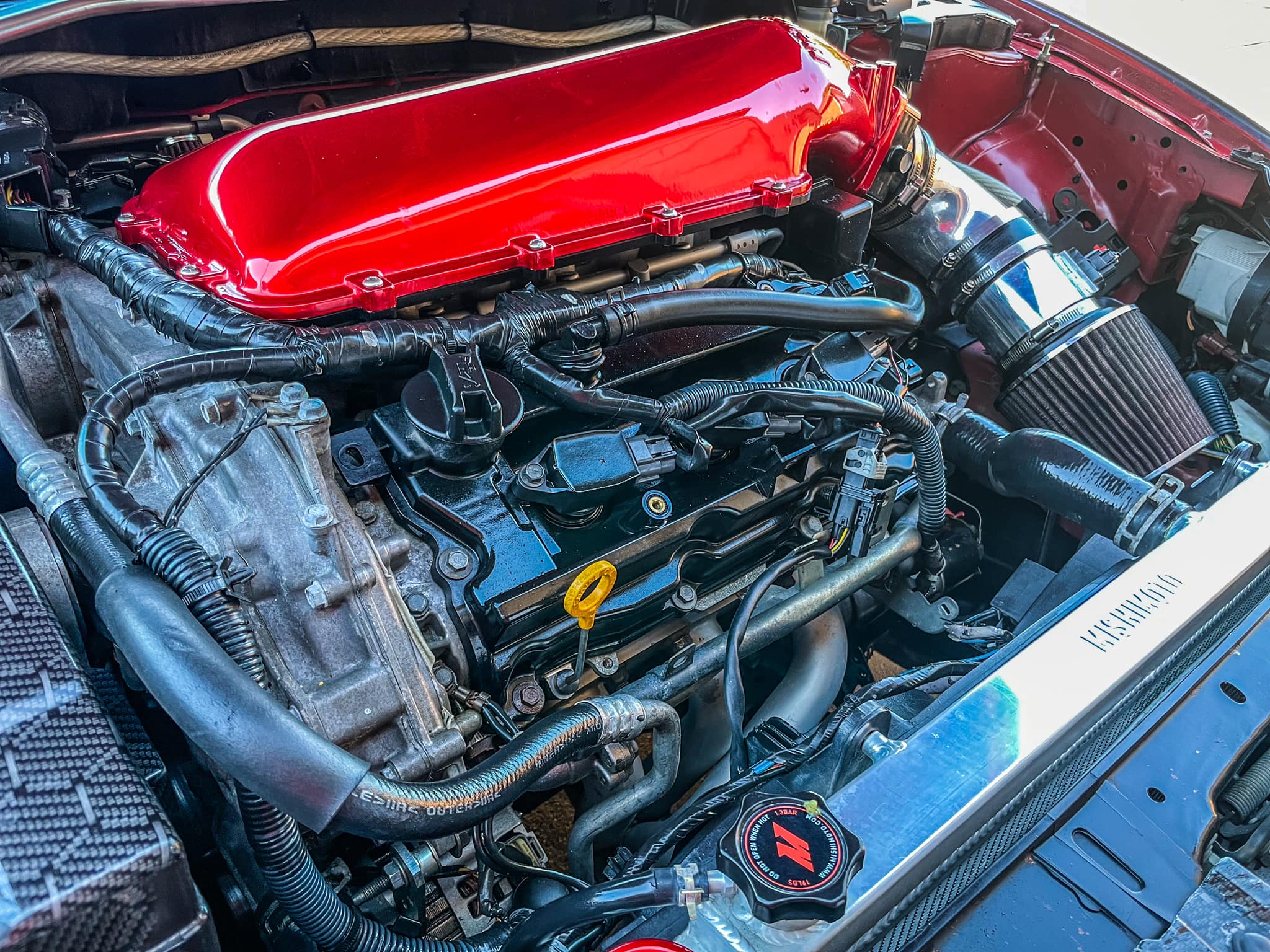
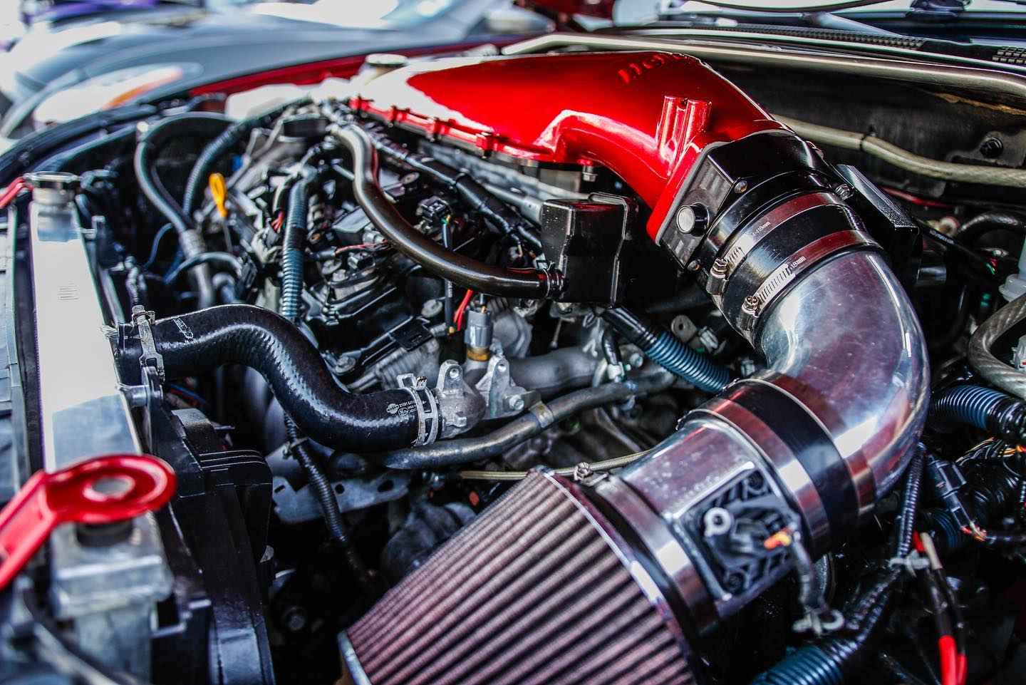
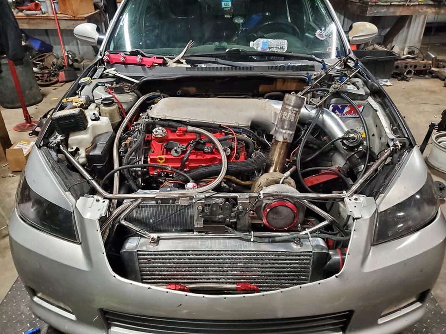
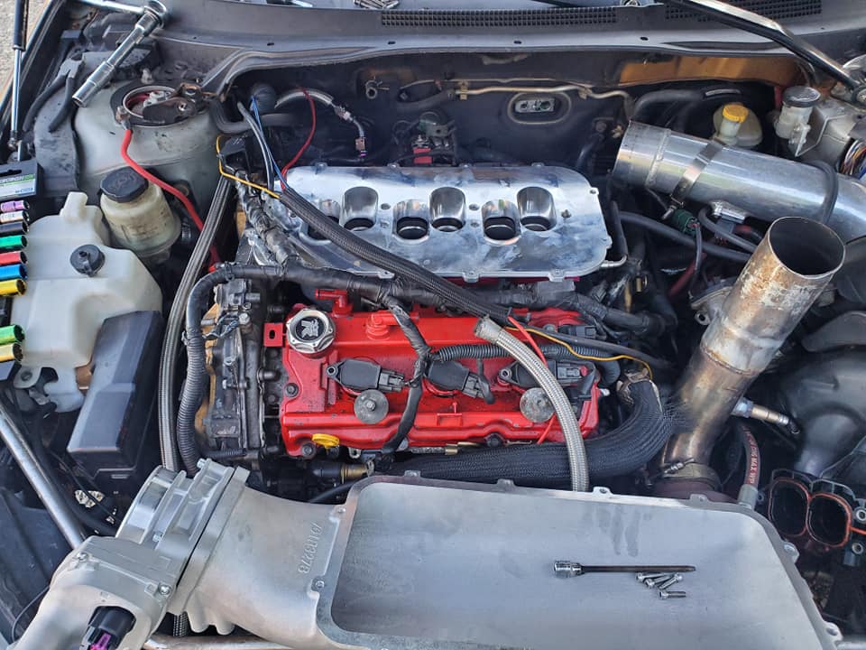
Front Mount Turbo Design
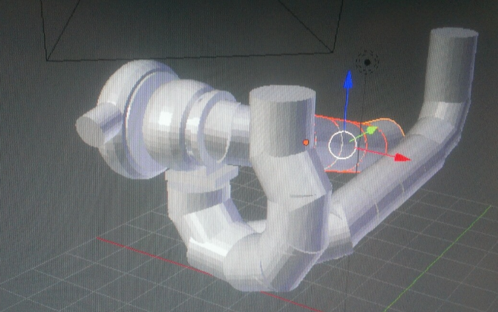
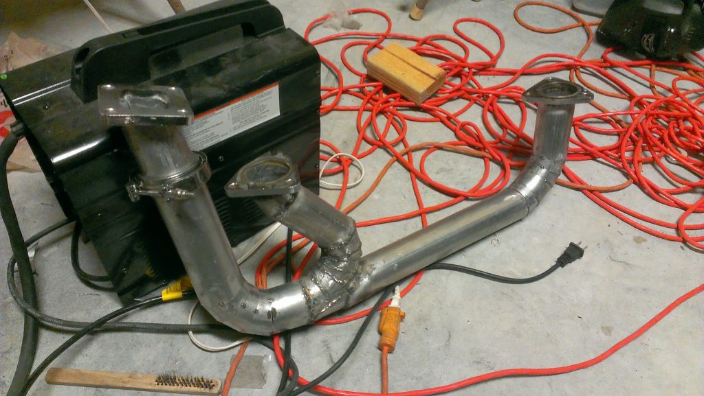
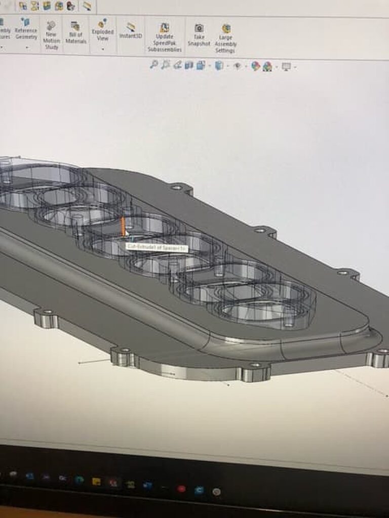
Fast forward several years and the car now garaged I was able to start gathering more tools and I was gifted a Harbor Freight 90amp Flux Core welder. Right away I started piecing together a front mount turbo kit in my mind. I started doing mock up 3D designs to get an idea and better visualize what I was going to do. I did not want to do the usual reverse y-pipe, or have to remove the battery, I wanted it to be efficient, and my own solution. This is the design I started with:
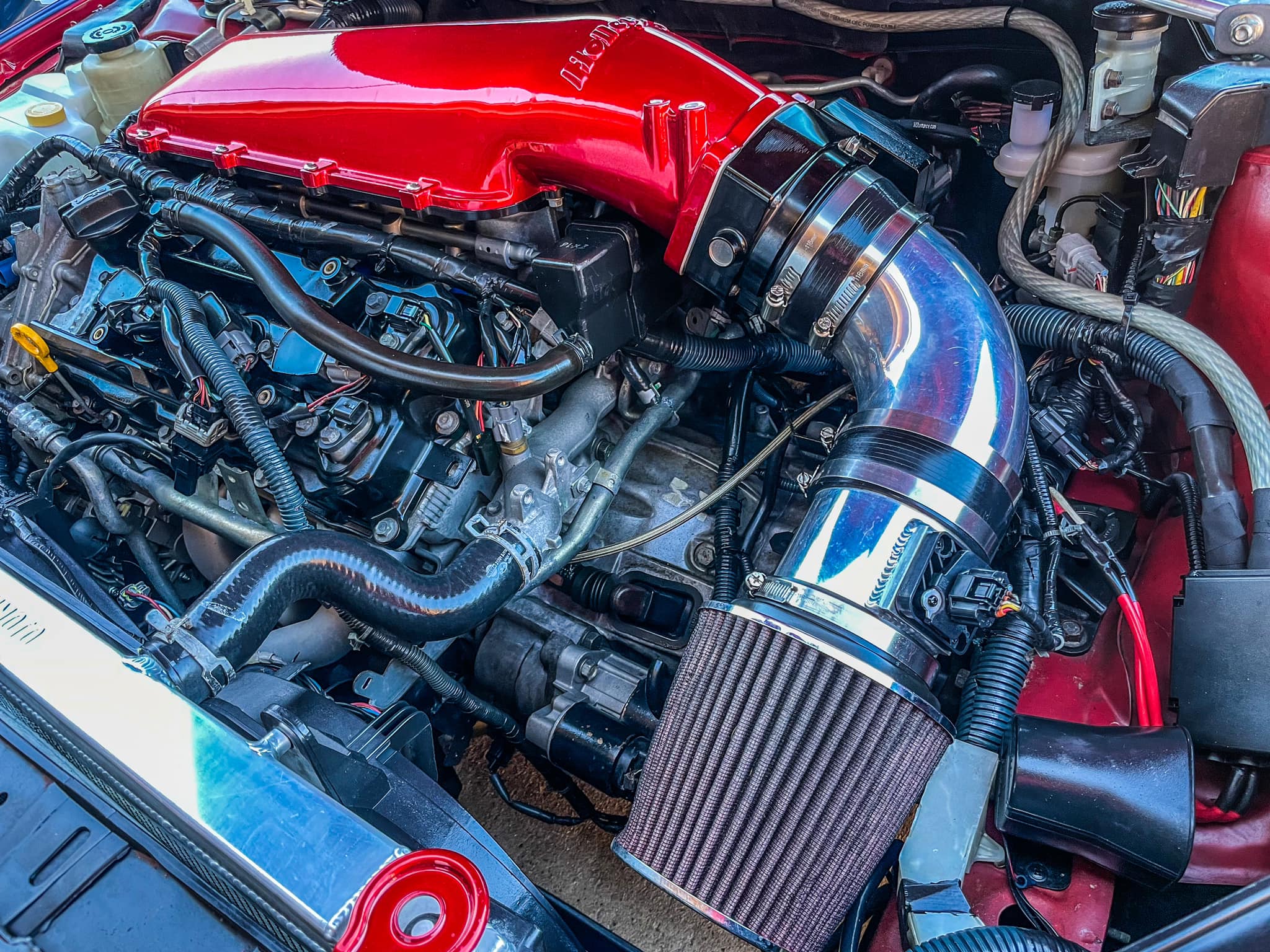
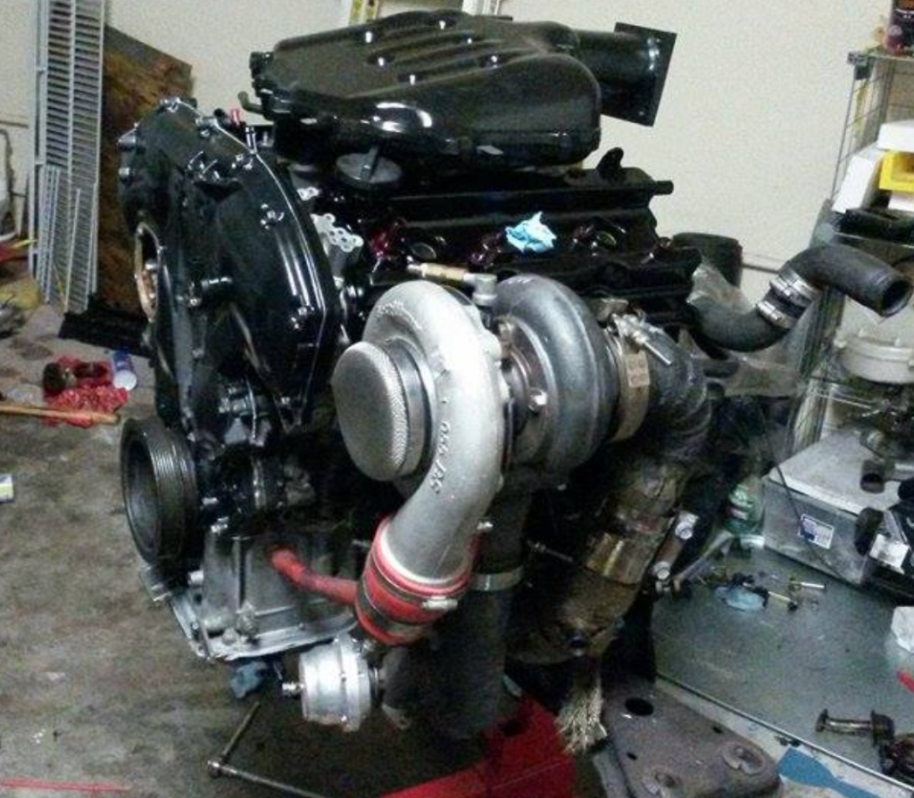
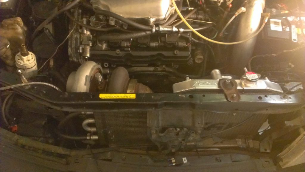
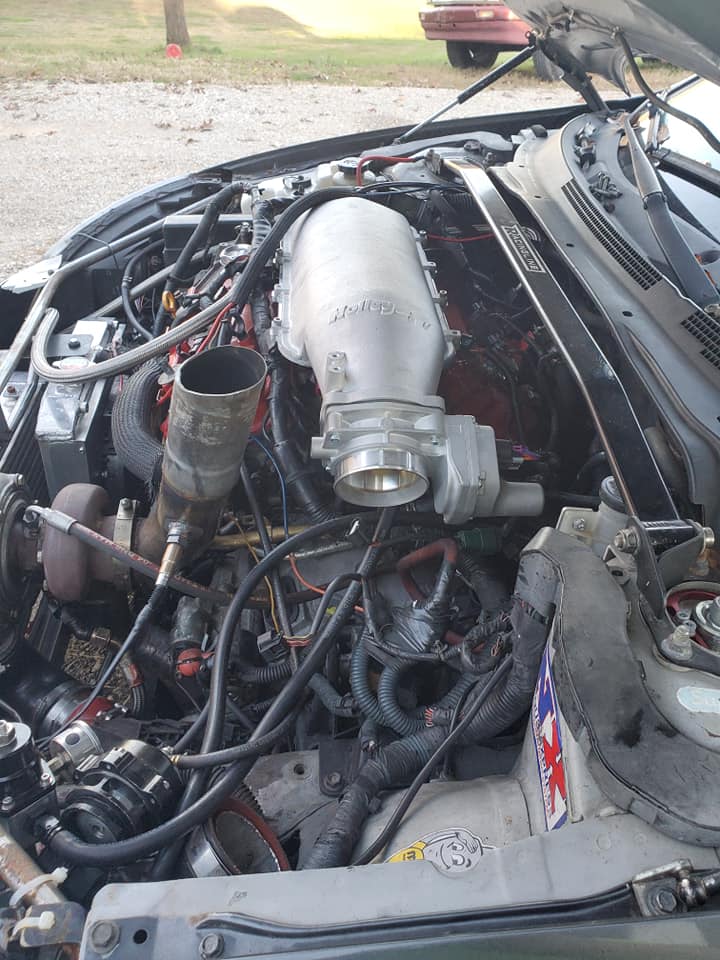
My plan was to place the turbo in the location of the AC compressor and remove the compressor. I mocked up the physical turbo to check the spacing in that area and I decided to put the turbo higher near the grill. Part of the reason for the new position was because I did not want to keep using a scavenge pump; the turbo would require one due to its low position.
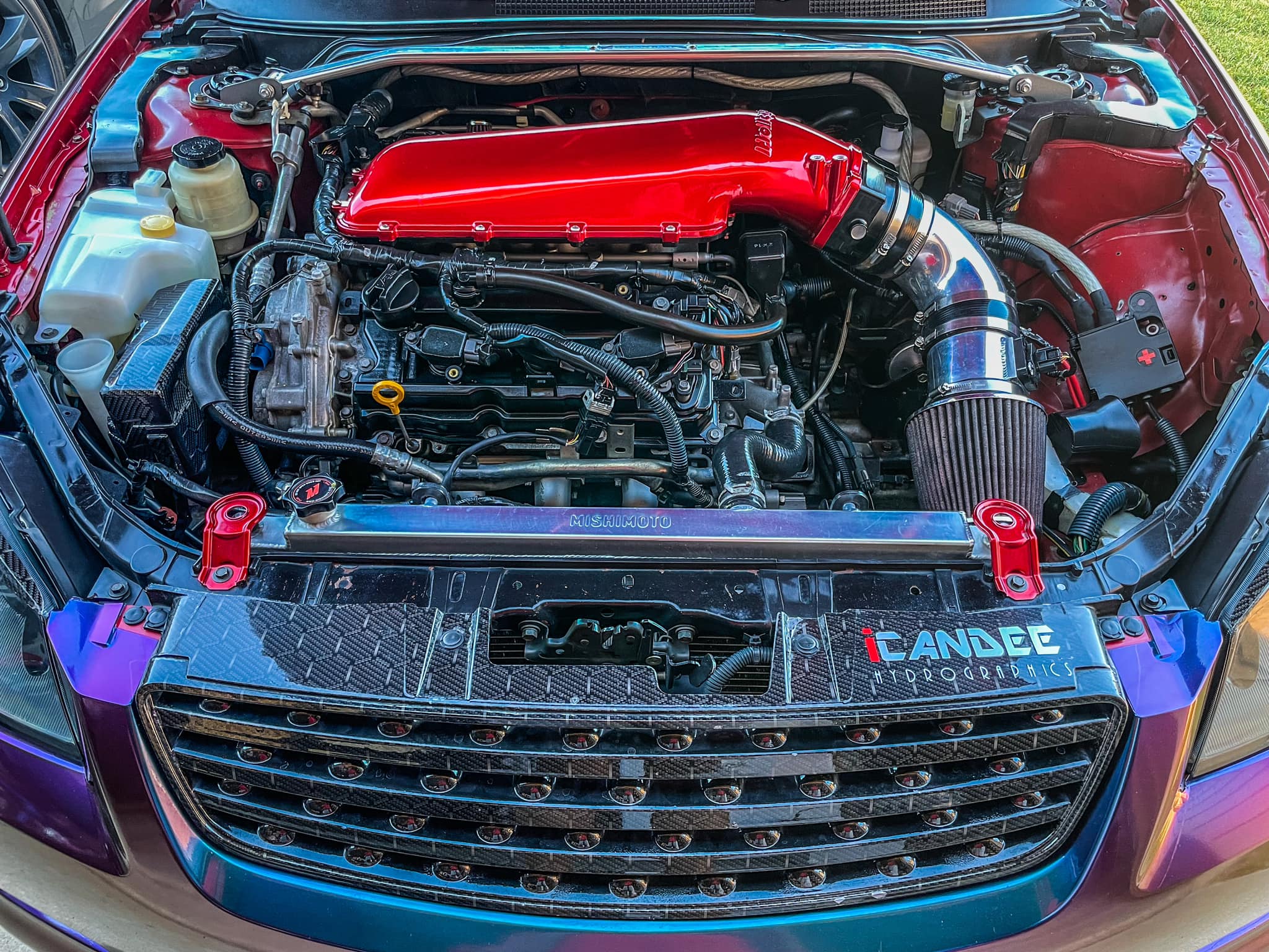
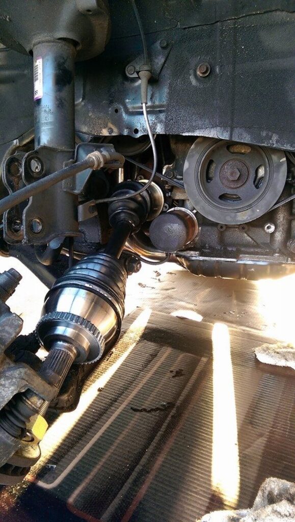
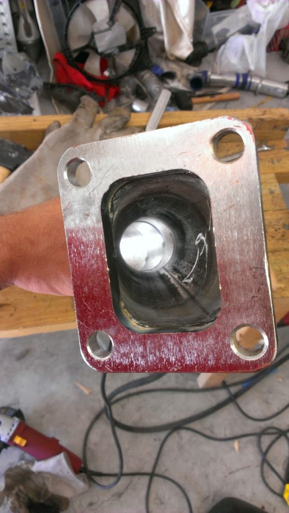
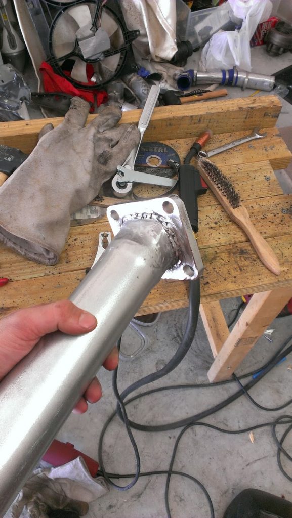
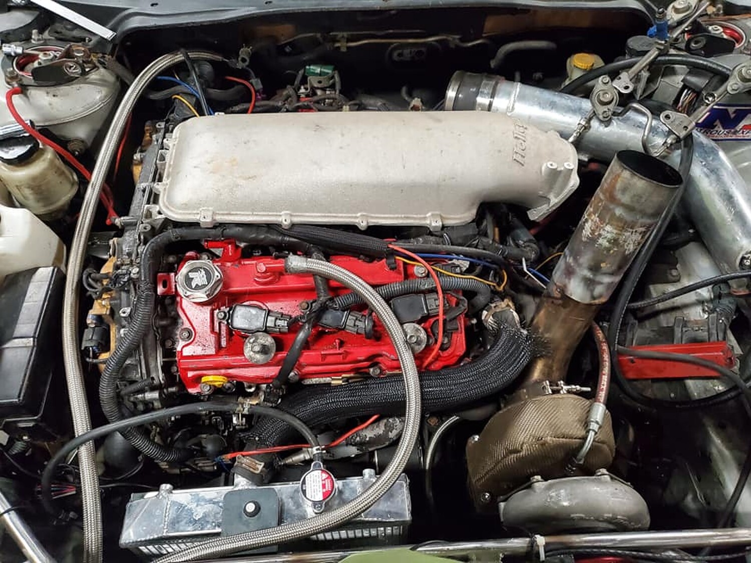
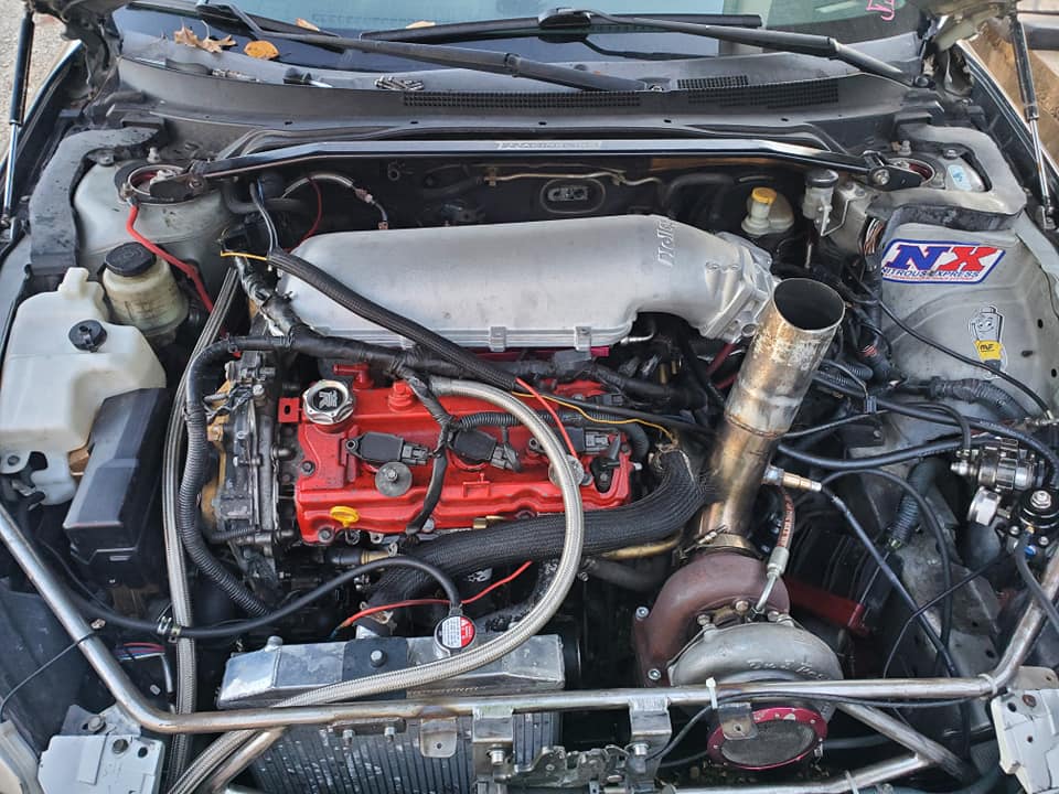
The headers were the factory iron ones, the flanges connecting to the header were reused from the Y Pipe previously used. The feed pipe has the same positioning as the Y Pipe except it aimed forward instead of the back, passing between the crossmember and the oil pan then up towards the alternator and above it. This new location required the use of a half size radiator. I used a Honda Del Sol 2 core with a custom shroud(It will be another blog entry). For the down pipe, you can see in the following pictures that I created a bend from the turbo down to the crossmember. The pipe then turns towards the back of the car and goes in parallel with the feed pipe (y pipe). After the feed pipe the downpipe continues on to the cat back like the exhaust system normally would. Here is the final location:
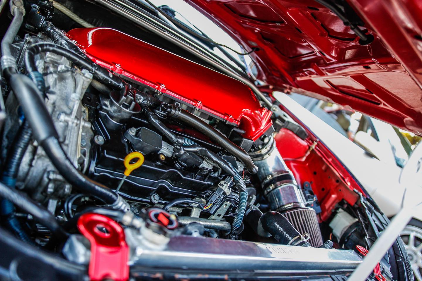
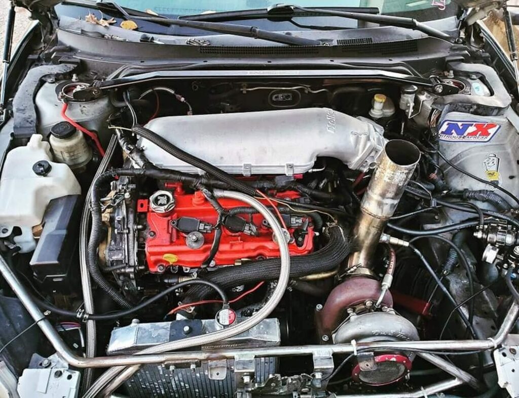
This video shows the initial engine start up after finishing the turbo kit. This was with the same turbo that was in the rear mount setup, which was an HX40Pro with a Bullseye .70AR turbine housing. This turbo’s spool up was quick as a rear mount and as a front mount with little travel it was instant.
Some of the details of this build:
Turbo: HX40Pro with a Bullseye .70AR
Wastegate: Tial 38mm, open to atmosphere
Blowoff Valve: Tial 50mm
Injectors: ID 1000cc
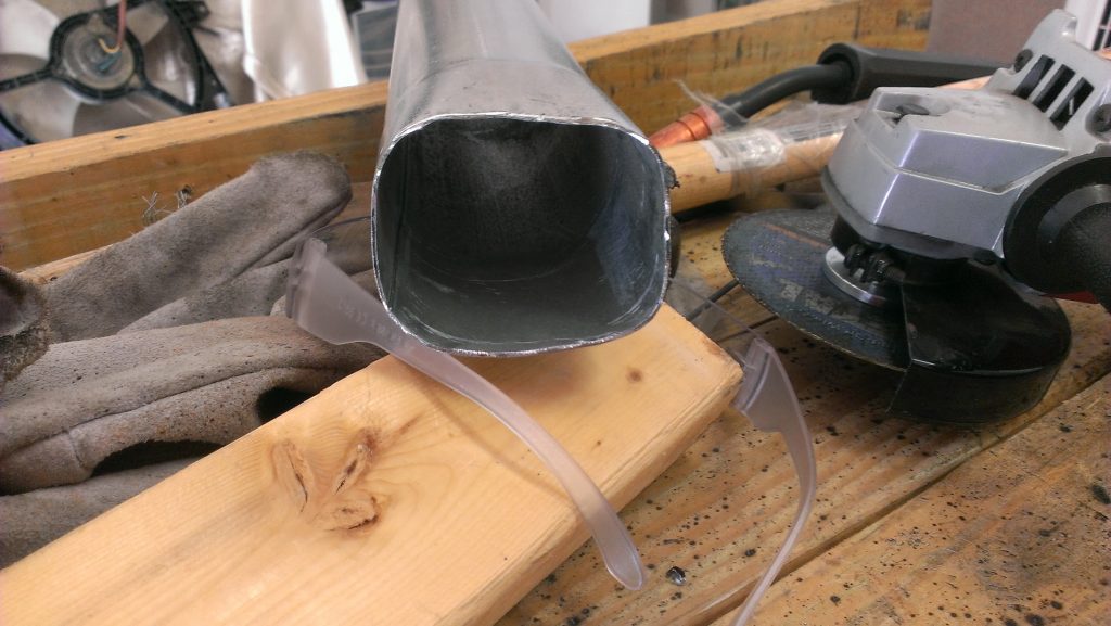
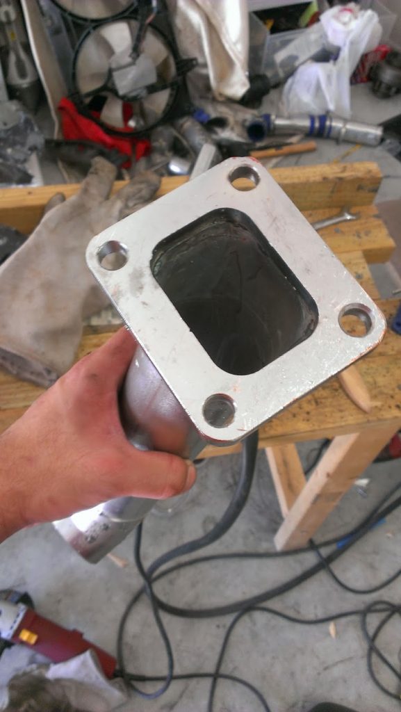
Turbo feed pipe size has 2.25in legs coming off the headers and merging into 2.5inch up to the turbo. There is a v-band in place before the turbine to be able to swivel the turbo around.
I cannot compare between Rear Mount and Front Mount because they had different turbos, I only drove the car briefly with the HX40 before I upgraded it so I do not have data to compare. But most certainly the response time for the turbo was different; the difference between the turbo being in the very rear of the car vs. being at the front was noticeable.
In the next post ill go over the cooling aspect of the setup and how I used a small radiator.
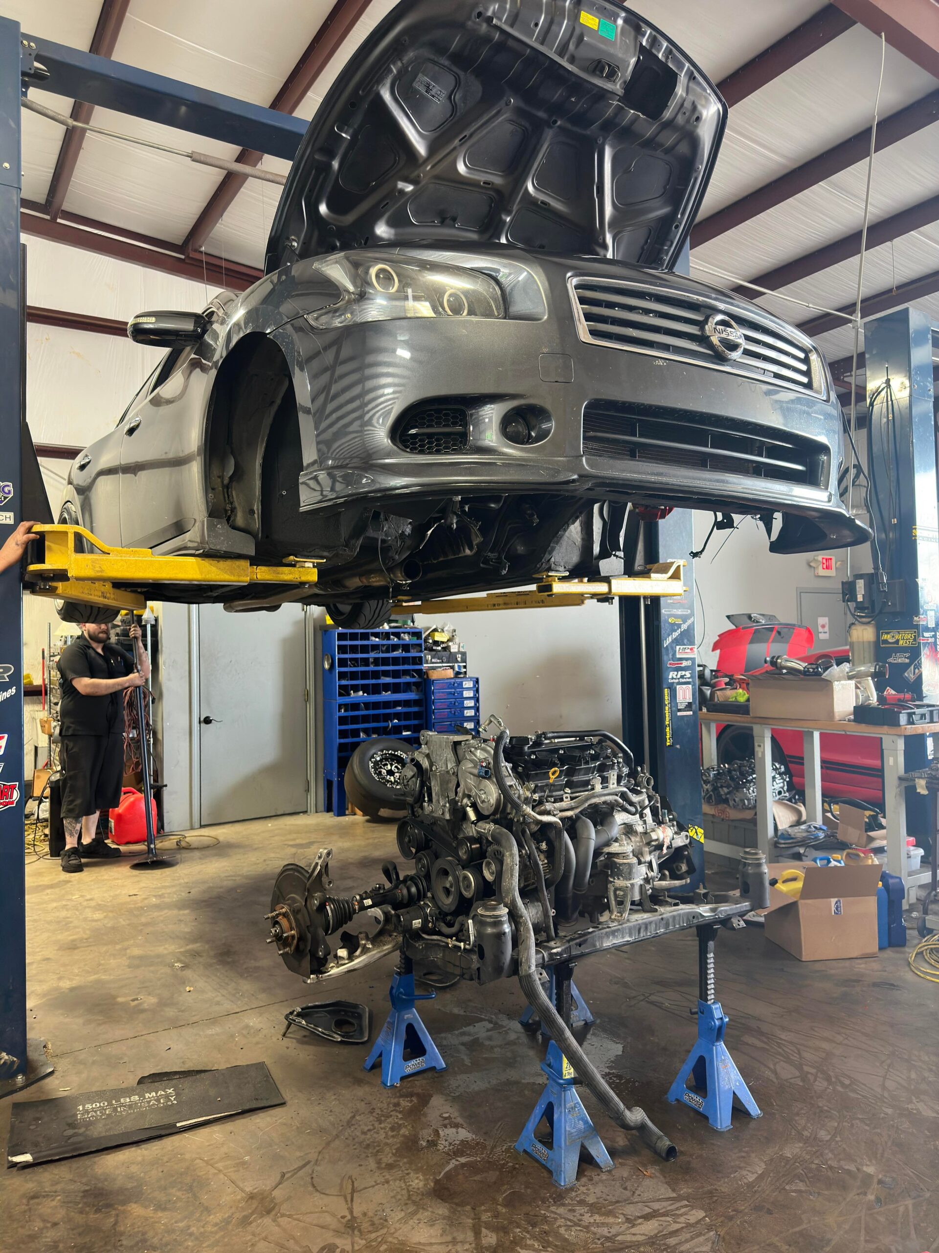
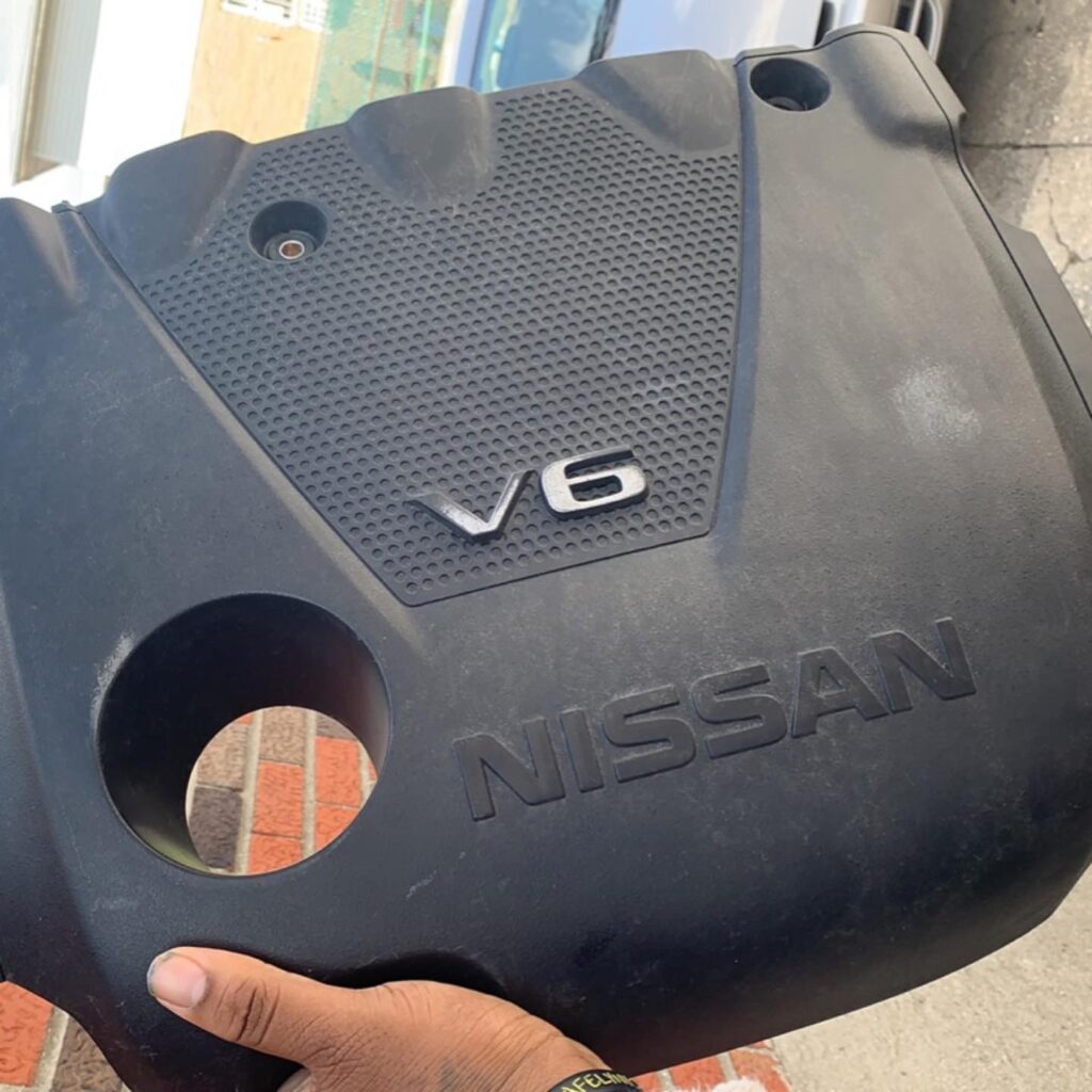
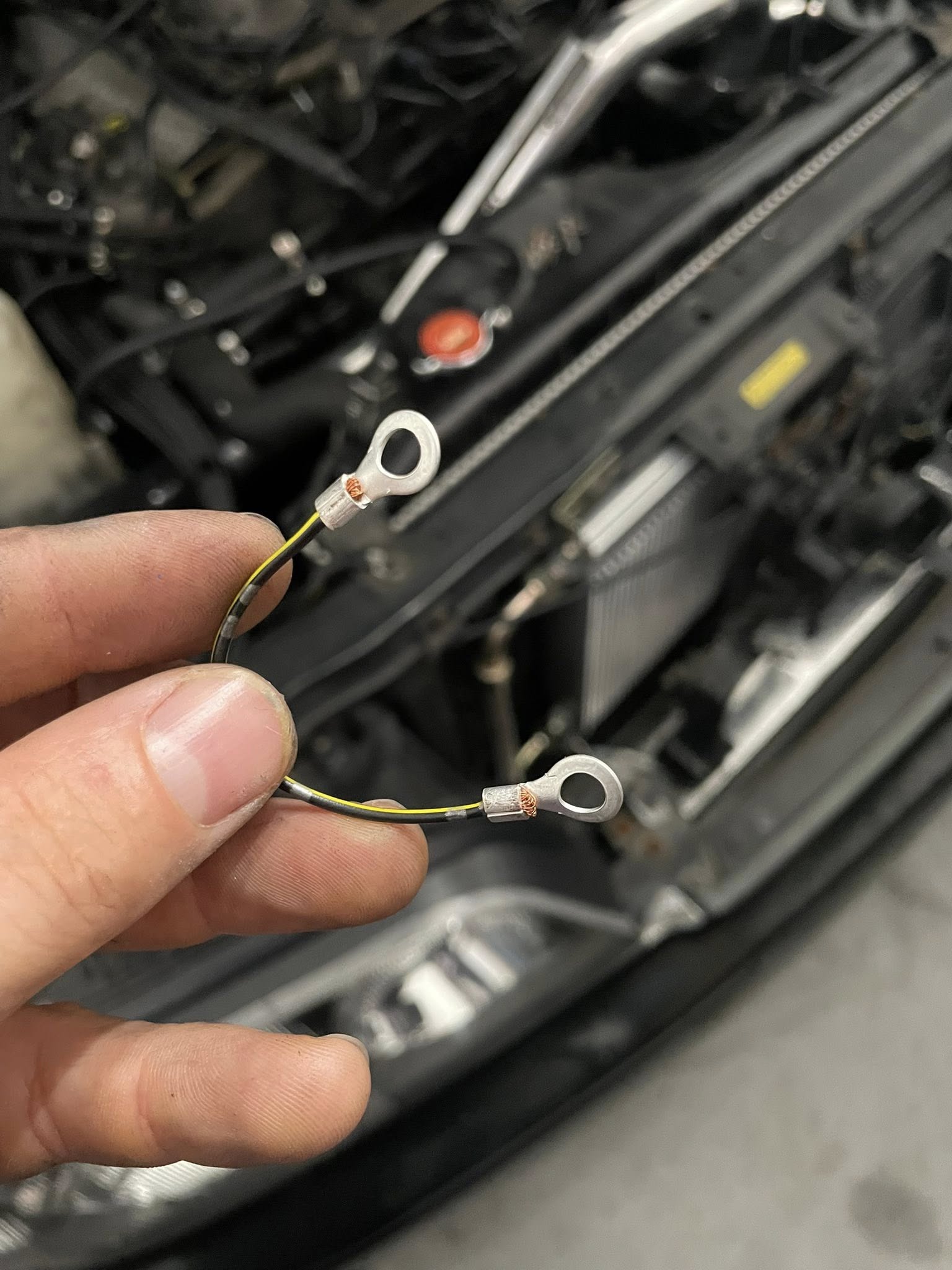
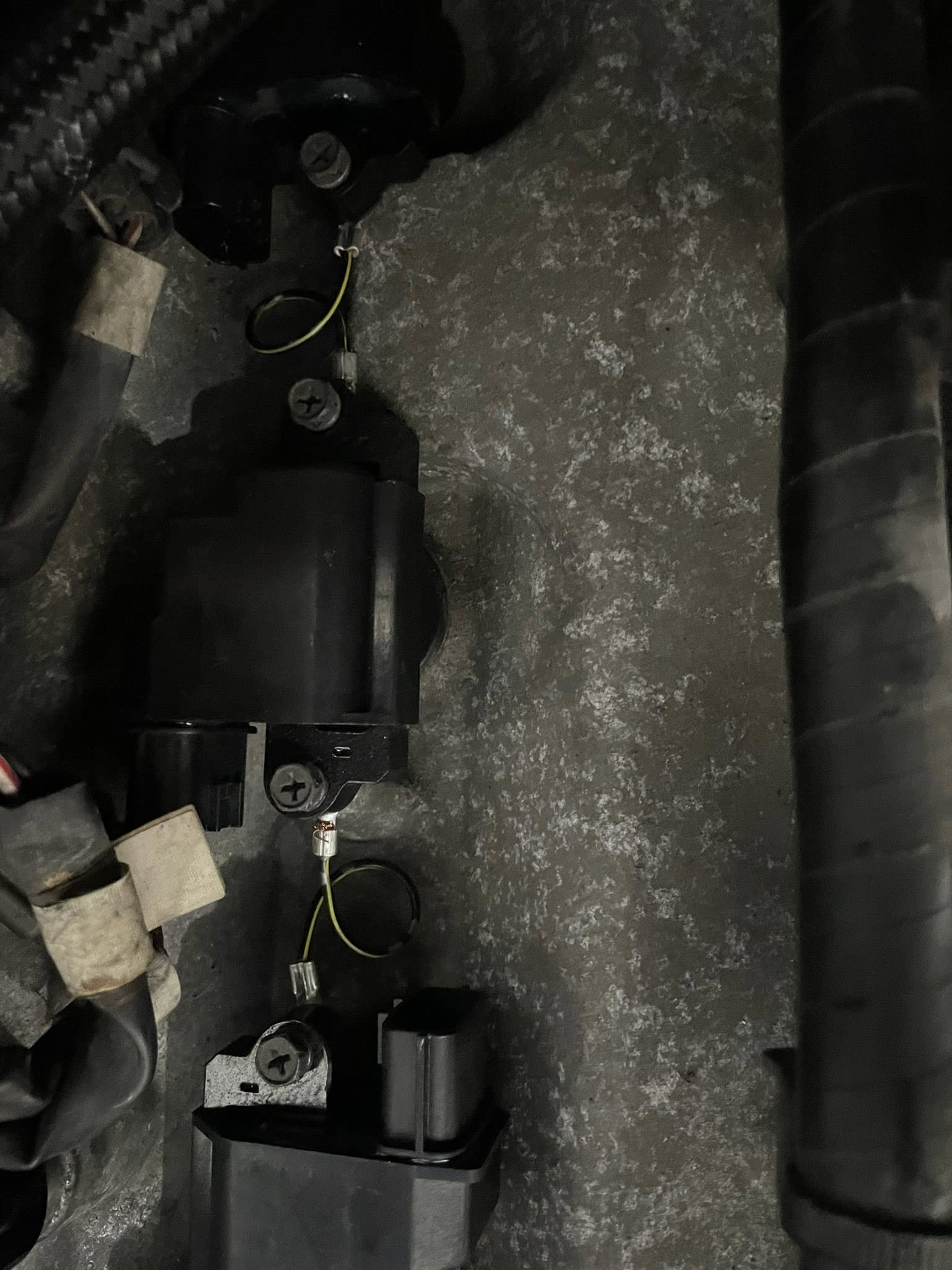
When doing the HR Swap on your Nissan Maxima, you use the DE knock sensor and DE harness since you are using the original wiring harness and ECU to your car.
DO NOT use the fwd hr knock sensor, it’s NOT set up for the DE ECU. You need to use the KNOCK sensor from your original engine.
The HR knock sensor doesn’t get ground from the motor, you need to add a ground to the other pin of the connector.
You can also use a 470K ohm resistor to bypass the knock sensor
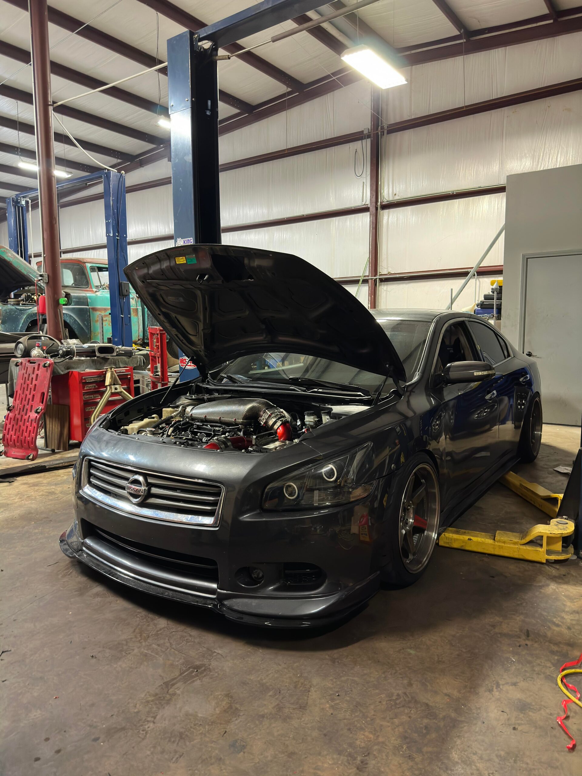
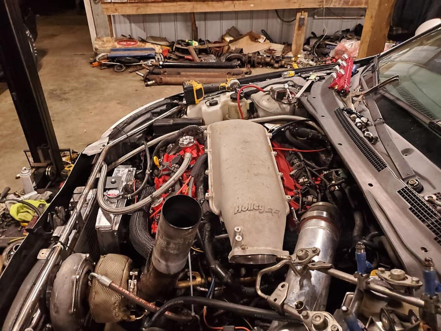
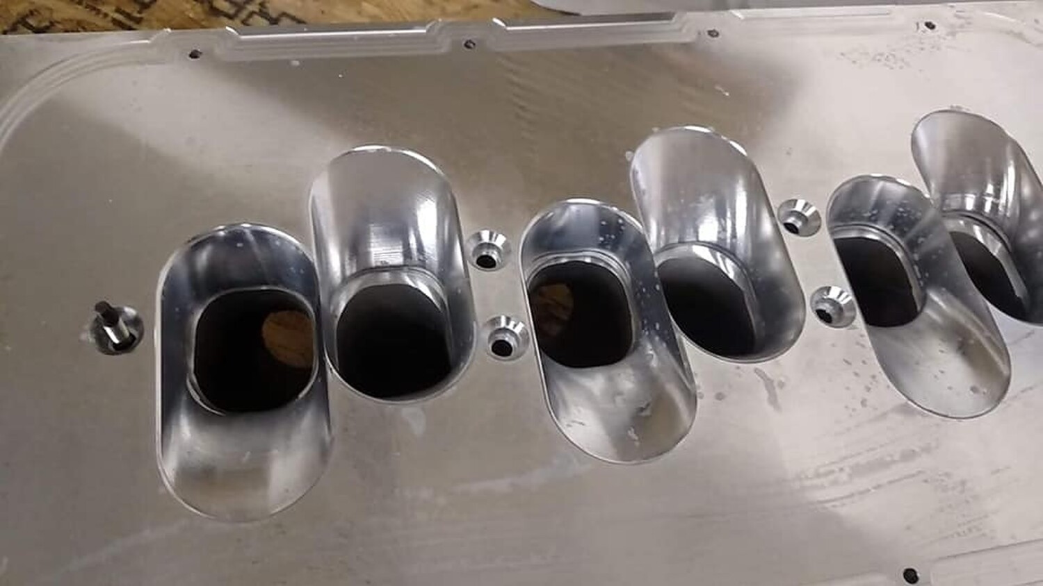
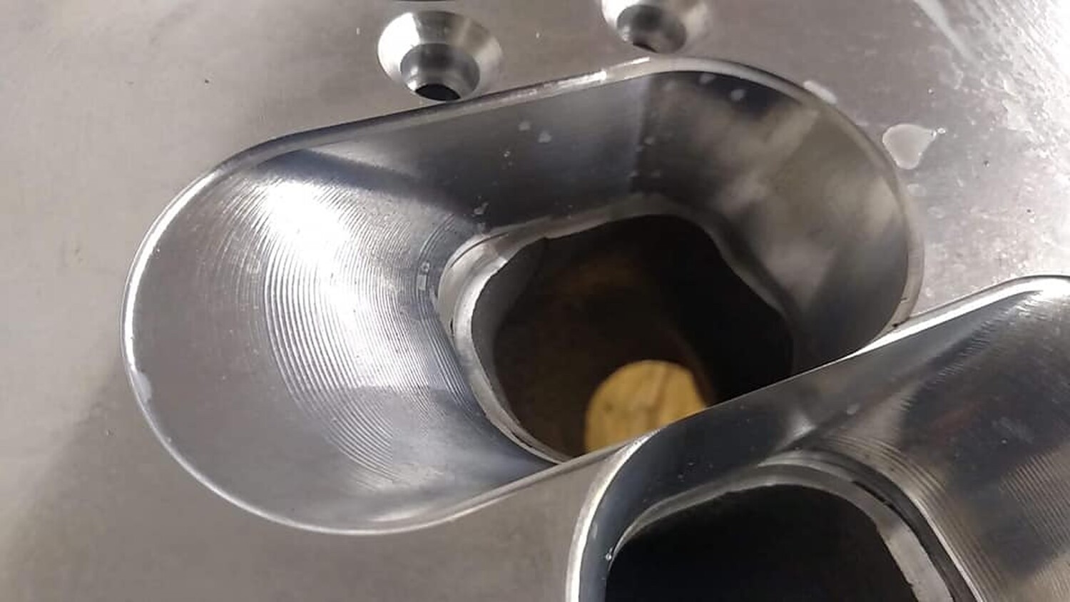
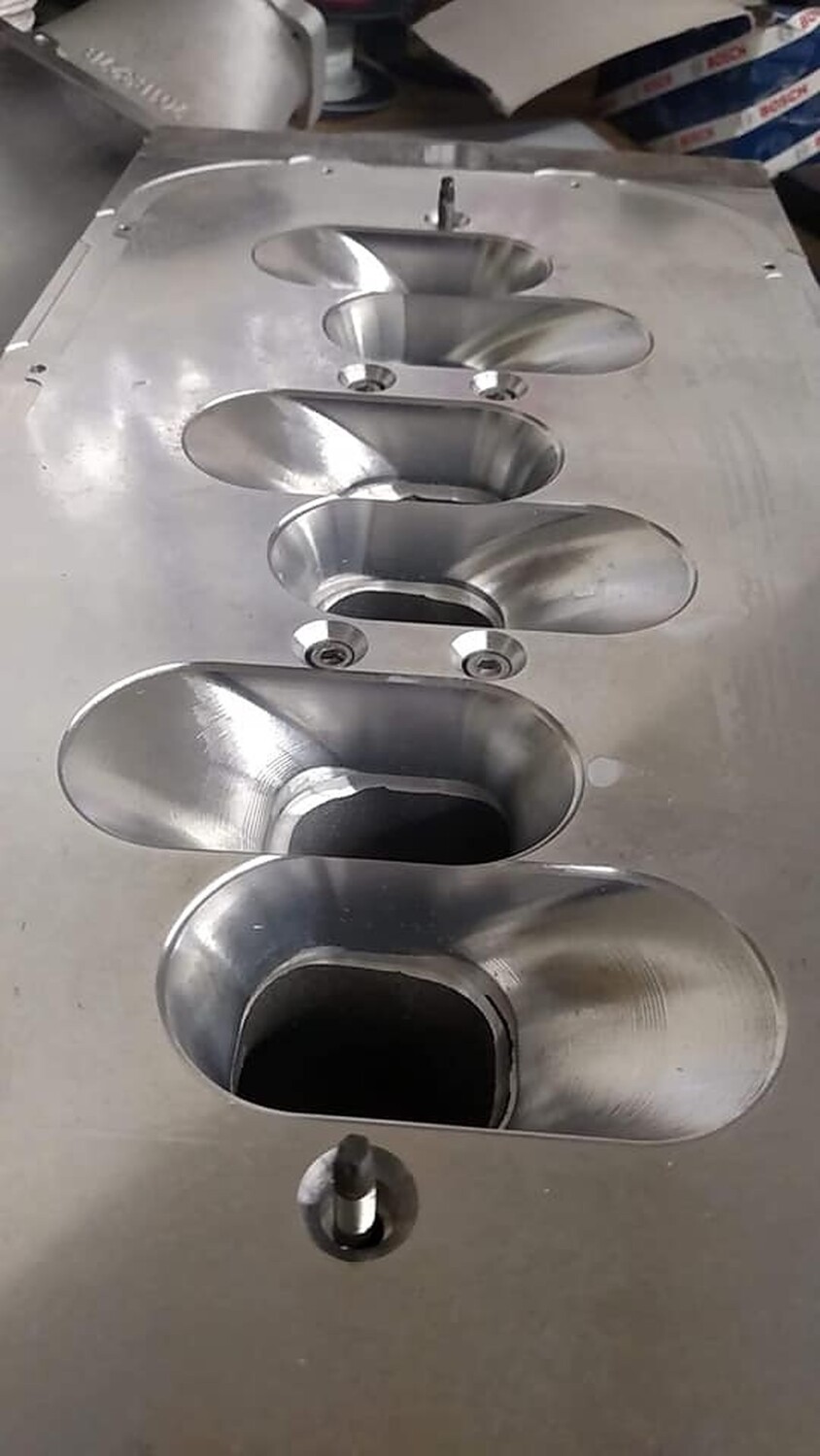
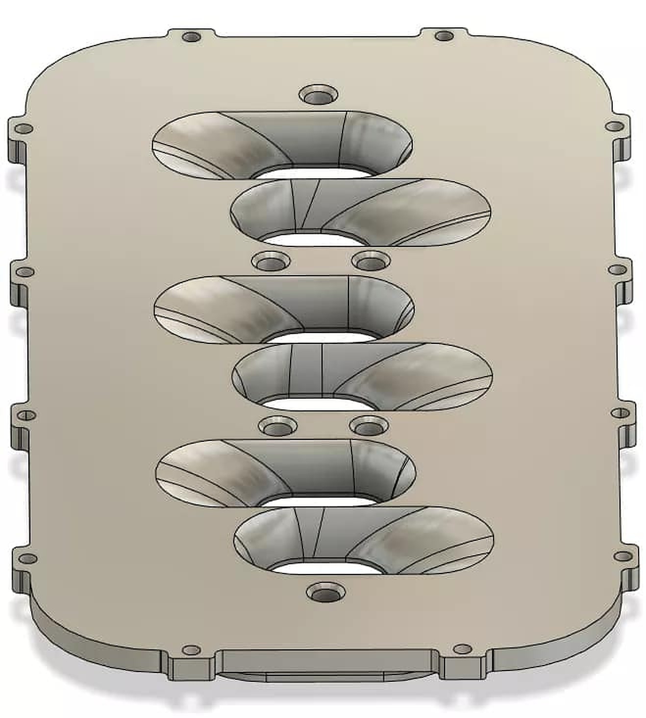
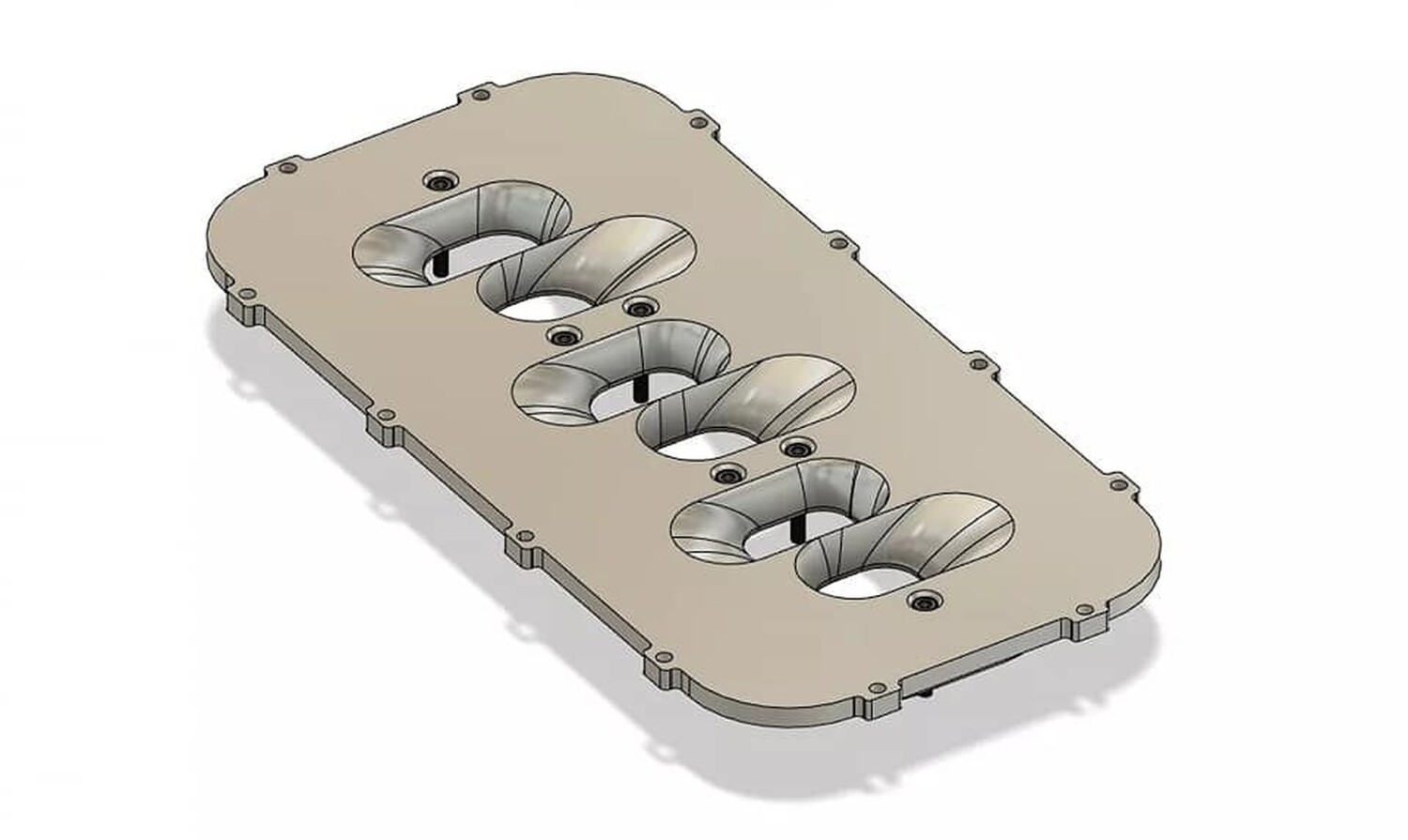
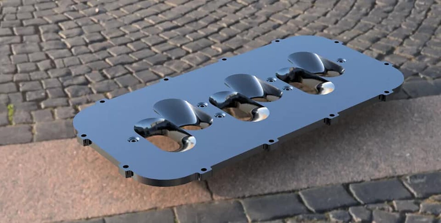
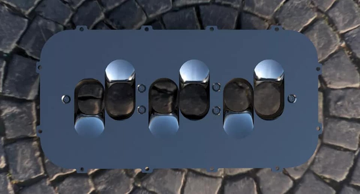
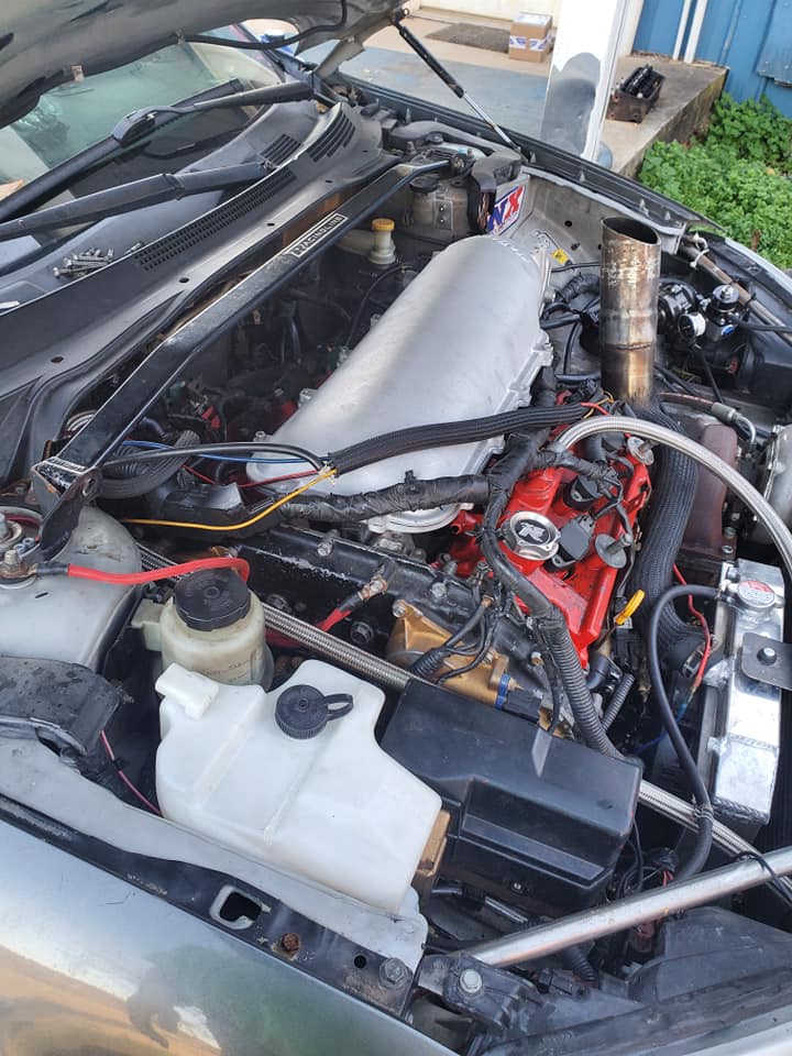
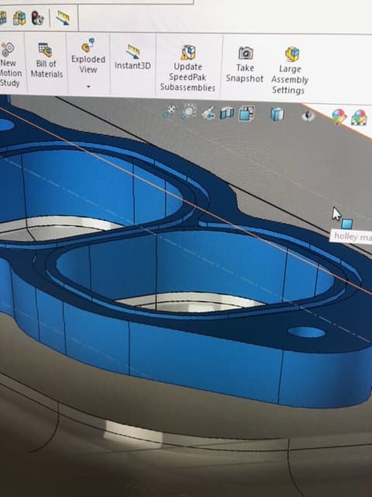
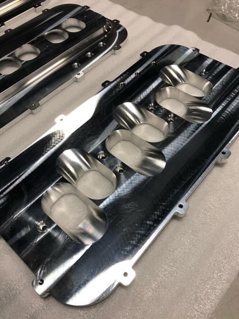
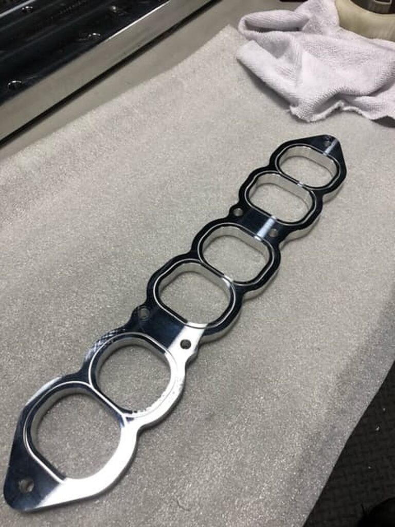
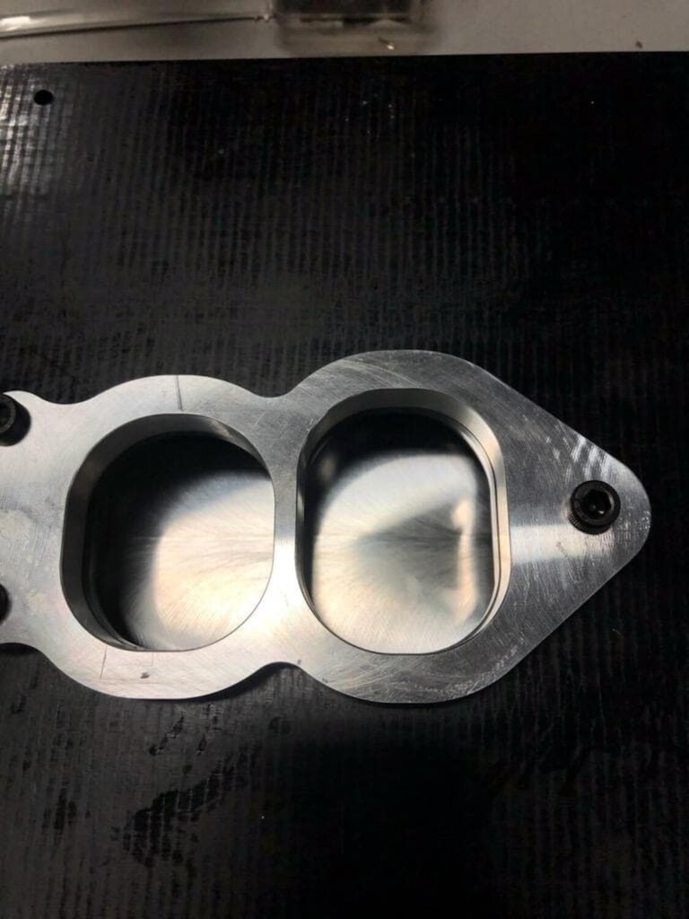
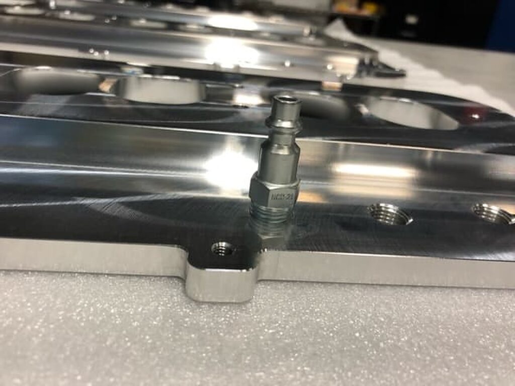
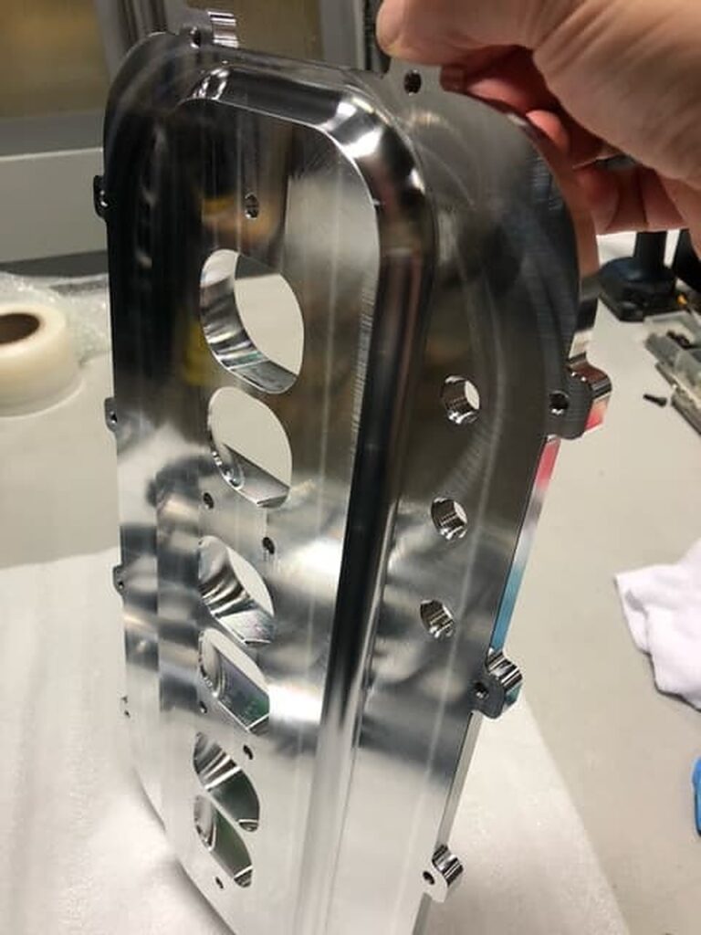
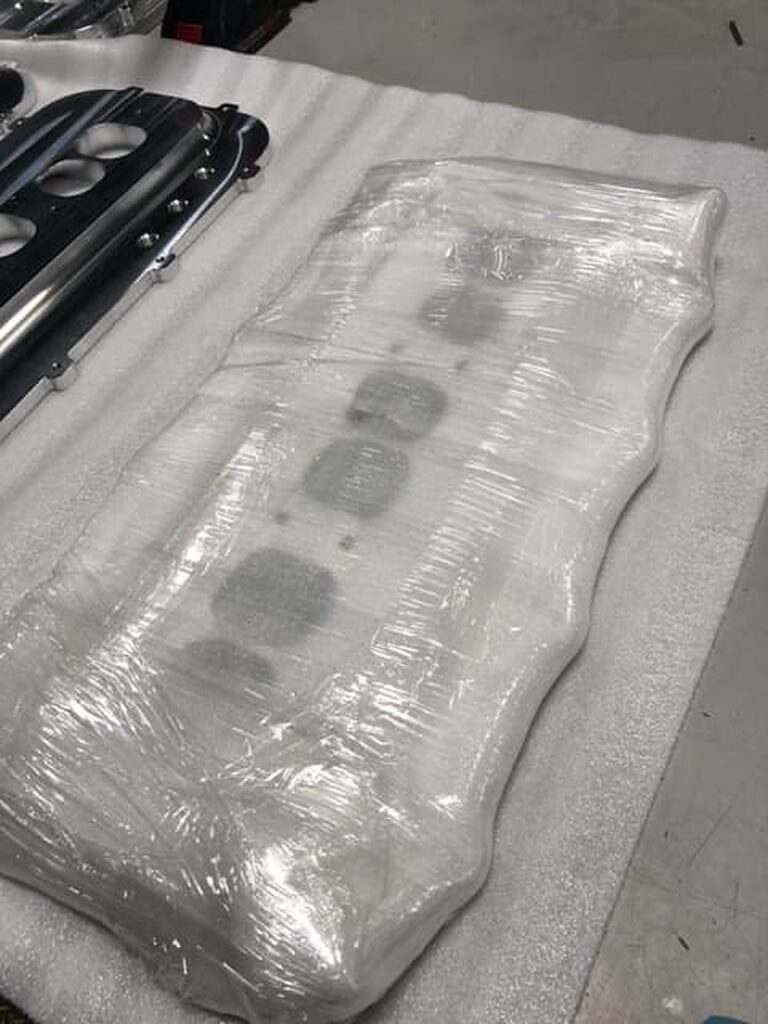
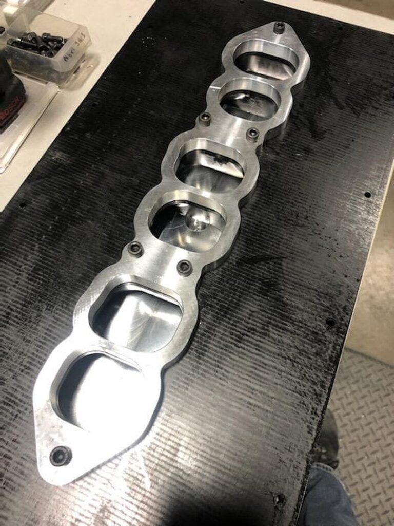
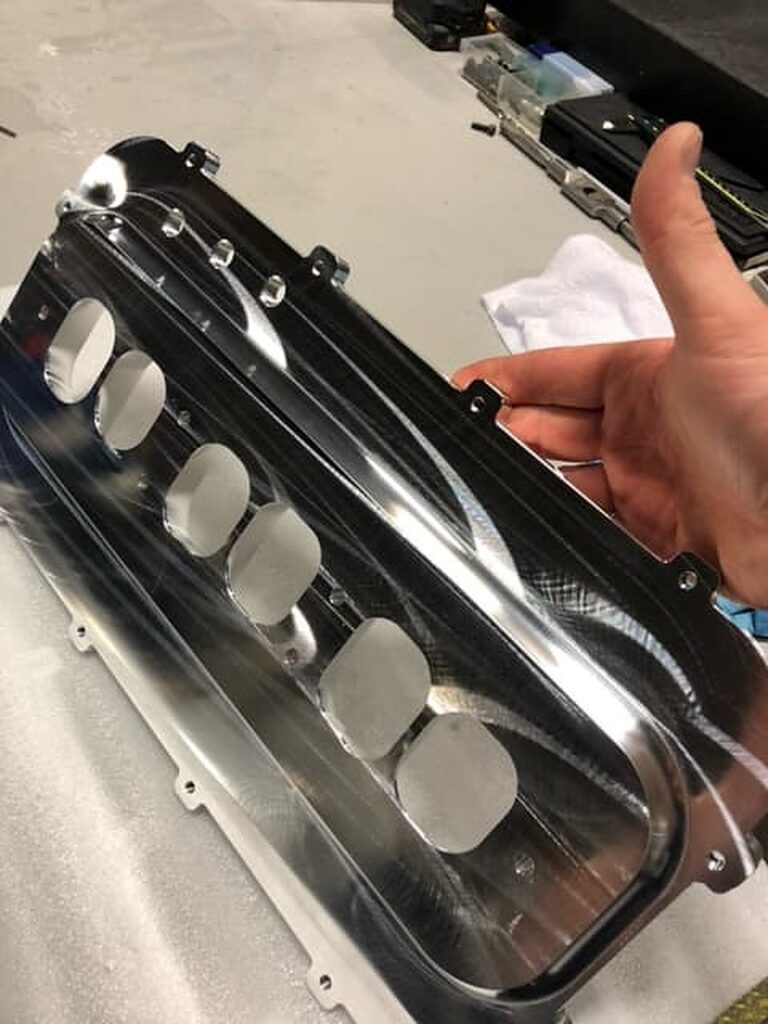
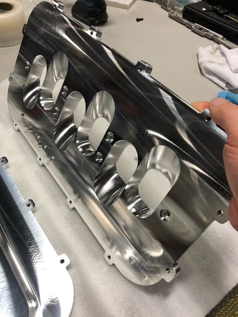
This is a Holley EFI plenum adapter for the Gen2 VQ35DE gen de. I can get them made for the FWD DE, RWD DE, RWD HR and even the 3.7. I’ve got a lot invested in this and those who are interested in this you need to be 100% interested in doing it because it’s gonna cost you about 1200 in total for everything and you’ll need to cut your hood.
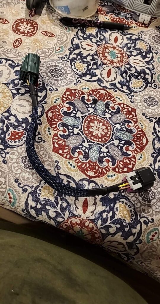
This will make a lot more power but will make a major difference in the higher RPMs. More specifically over 7k RPMs. This is a baller mod, for those who are serious and want to make serious power. The kit will consist of a lower adapter plenum upper plenum (Holley EFI 95mm) gm 90mm throttle body and a plug and play wiring harness for the throttle body. Dyno sheets will be up soon for direct comparison but you will need a tune to run this. This can fit a variety of cars if your willing to make it fit!


")
")
")

 Part Number for relief valve 15241-43UOA, you can see the broken one on the left I stretched the spring trying to unseat it. You can also see half of the ridge that retains the spring and ball bearing which cracked off. Over tightening the oil filter, metal fatigue(200K) ? It comes assembled in the new relief valve.