In this part two of the front mount turbo build I will go over making the radiator efficient enough to cool the engine in all conditions.
Some information about the car:
1997 Maxima
VQ35DE
Automatic
Turbo (initially rear mount turbo)
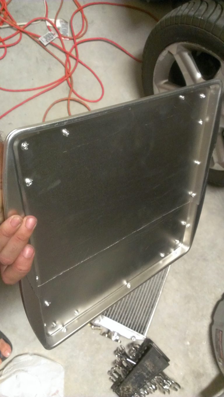
DIY Fan Shroud
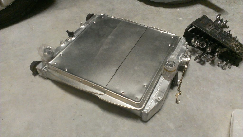
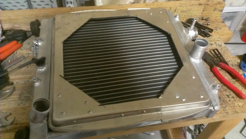
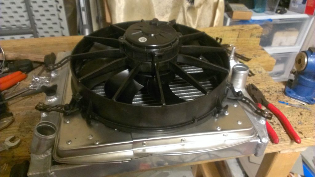
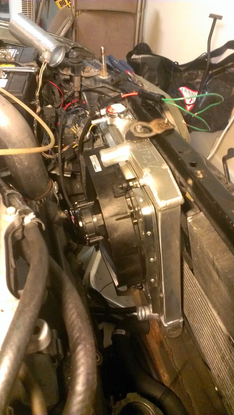
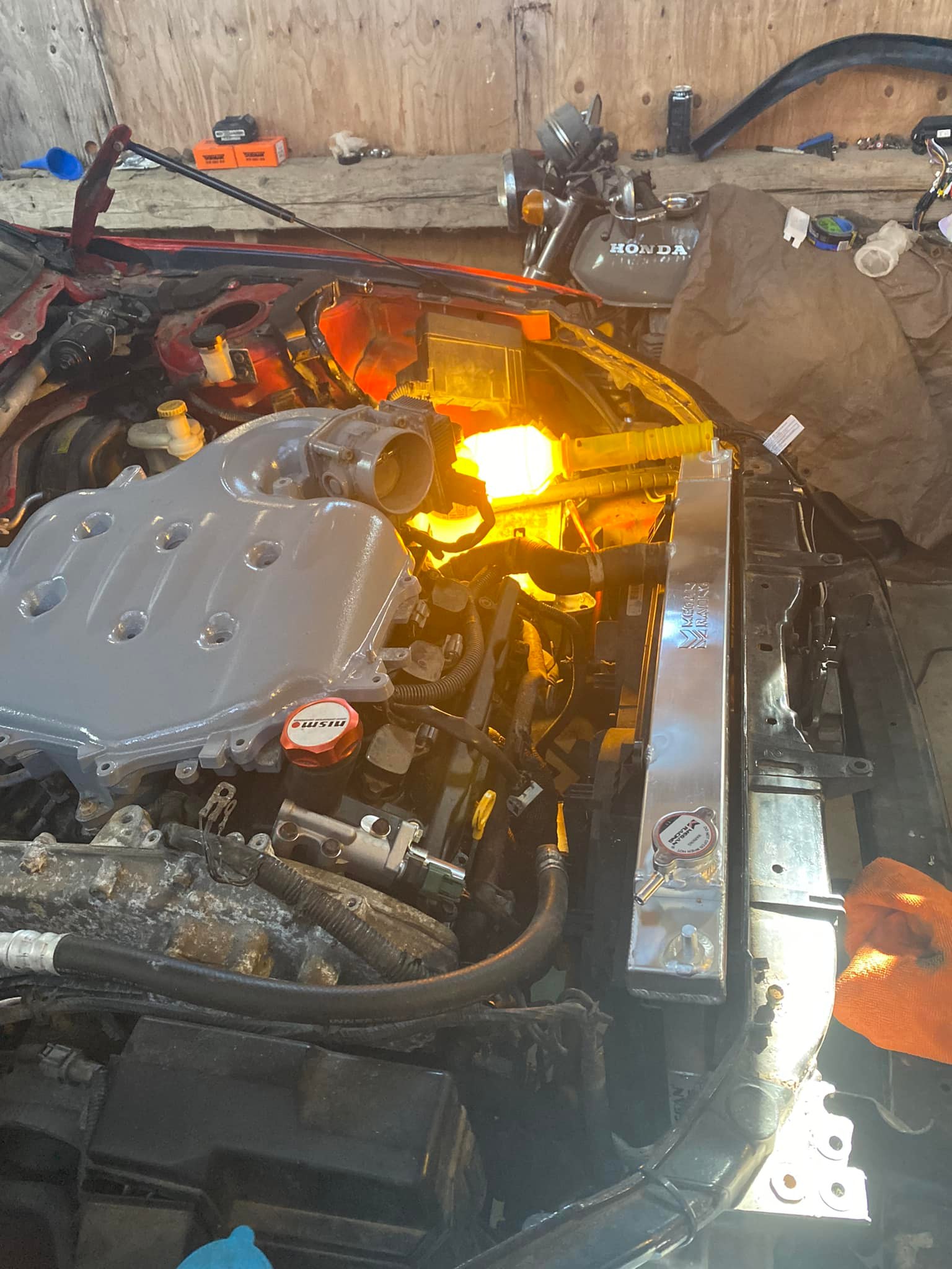
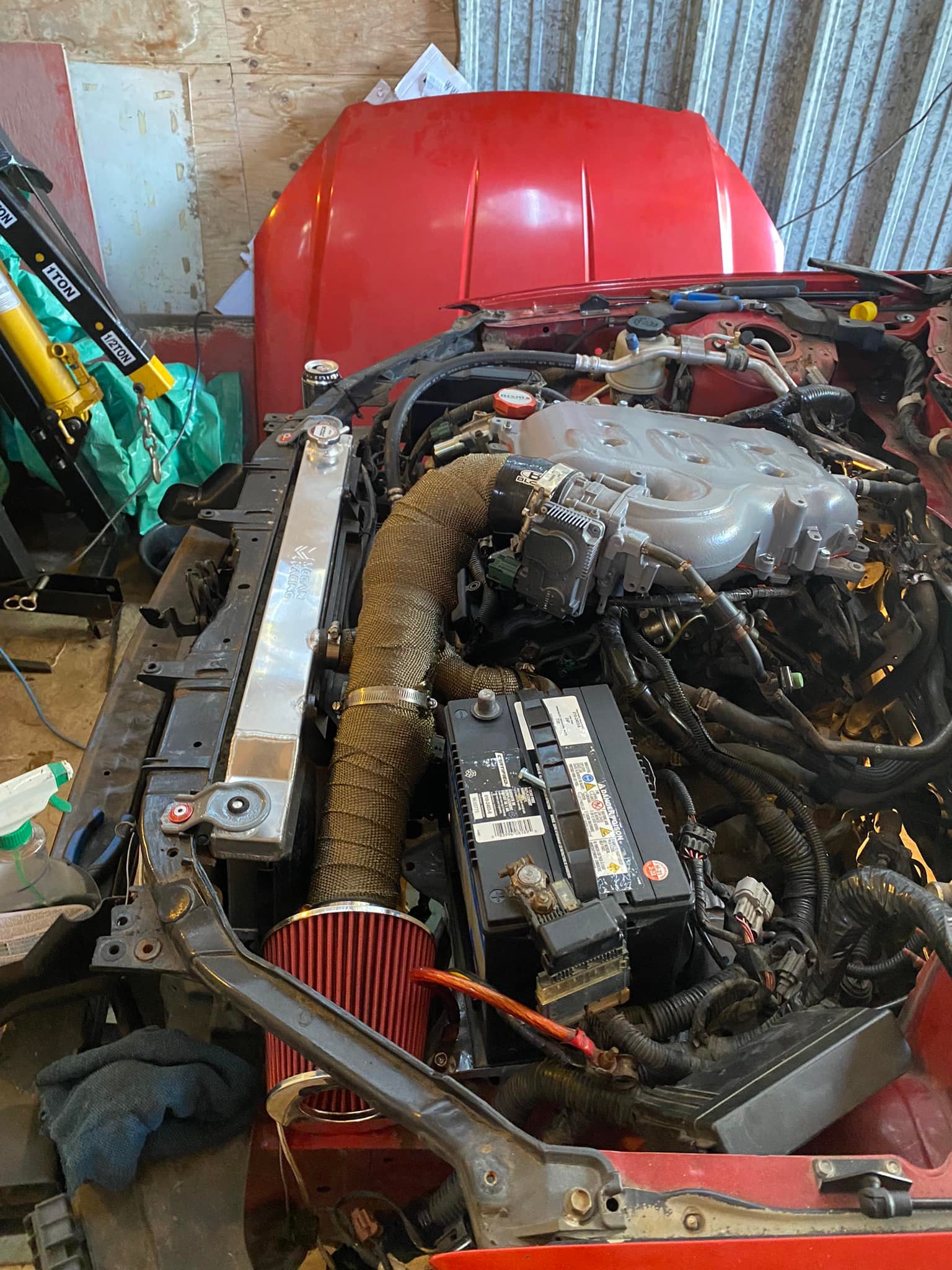
I used a generic brand radiator from eBay. It is a two core aluminum radiator for a Honda del Sol. The fan used is a Spal 12″ Curved Blade Puller Fan. With a pullIng fan it is important to use a shroud so that the air is pulled from all sections of the radiator. Having no shroud the fan will only pull air through the area where the fan is mounted too; limiting the cooling area to that diameter.
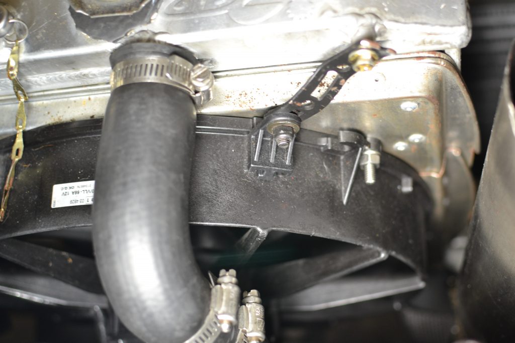
I created the Shroud using two cookie baking trays. I cut both of them in half then I overlaid the ends together so that I can have a specific width to cover the whole area needed. The tray is about a quarter inch to half an inch deep which means this is how far the trays floor will be away from the radiator; you want this distance or greater to help pull air from the corners of the radiator.
I then riveted the trays together to make a sturdy. I cut a hexagonal shape in the center with the same diameter as the fan (12″). To support it all, I used the brackets that came with the fan and bolted them to the radiator; I fastened the shroud to the radiator with through bolts.
Dealing with exhaust Heat
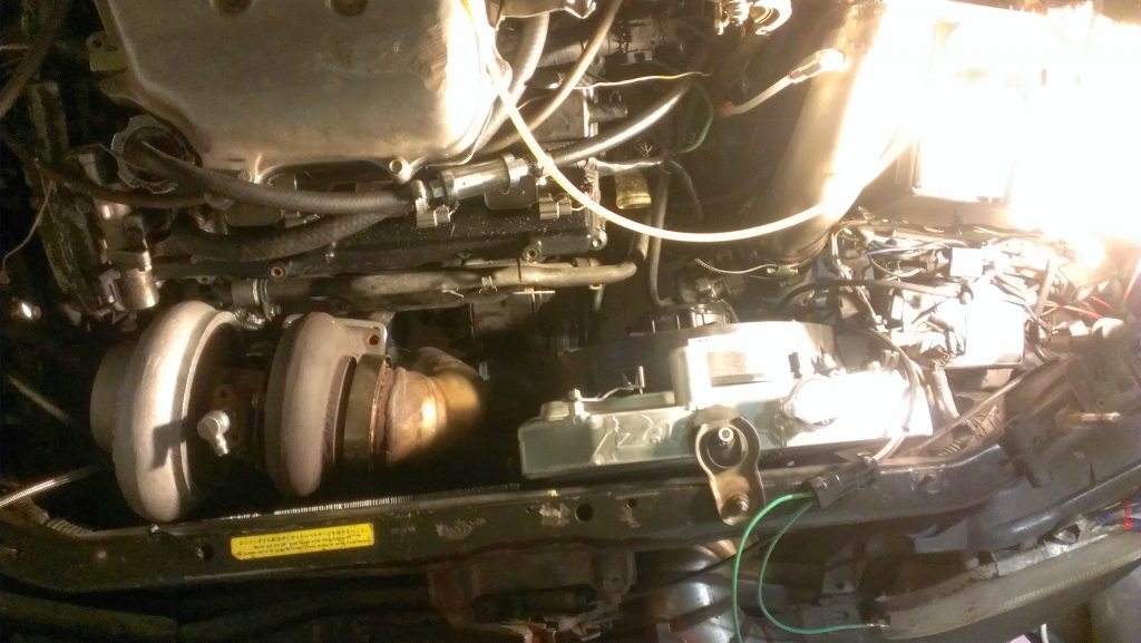
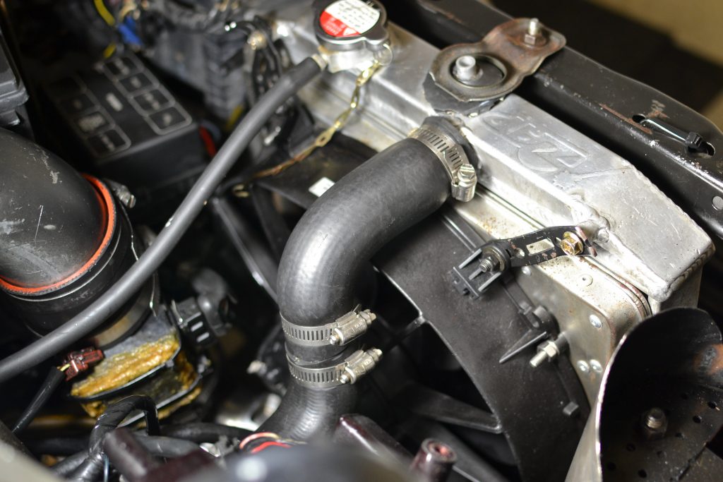
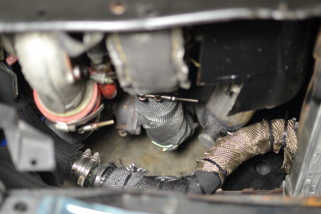
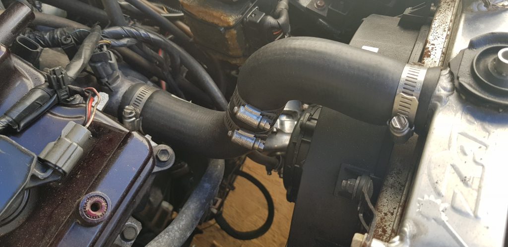
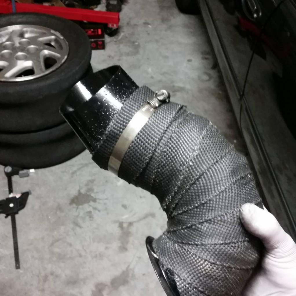
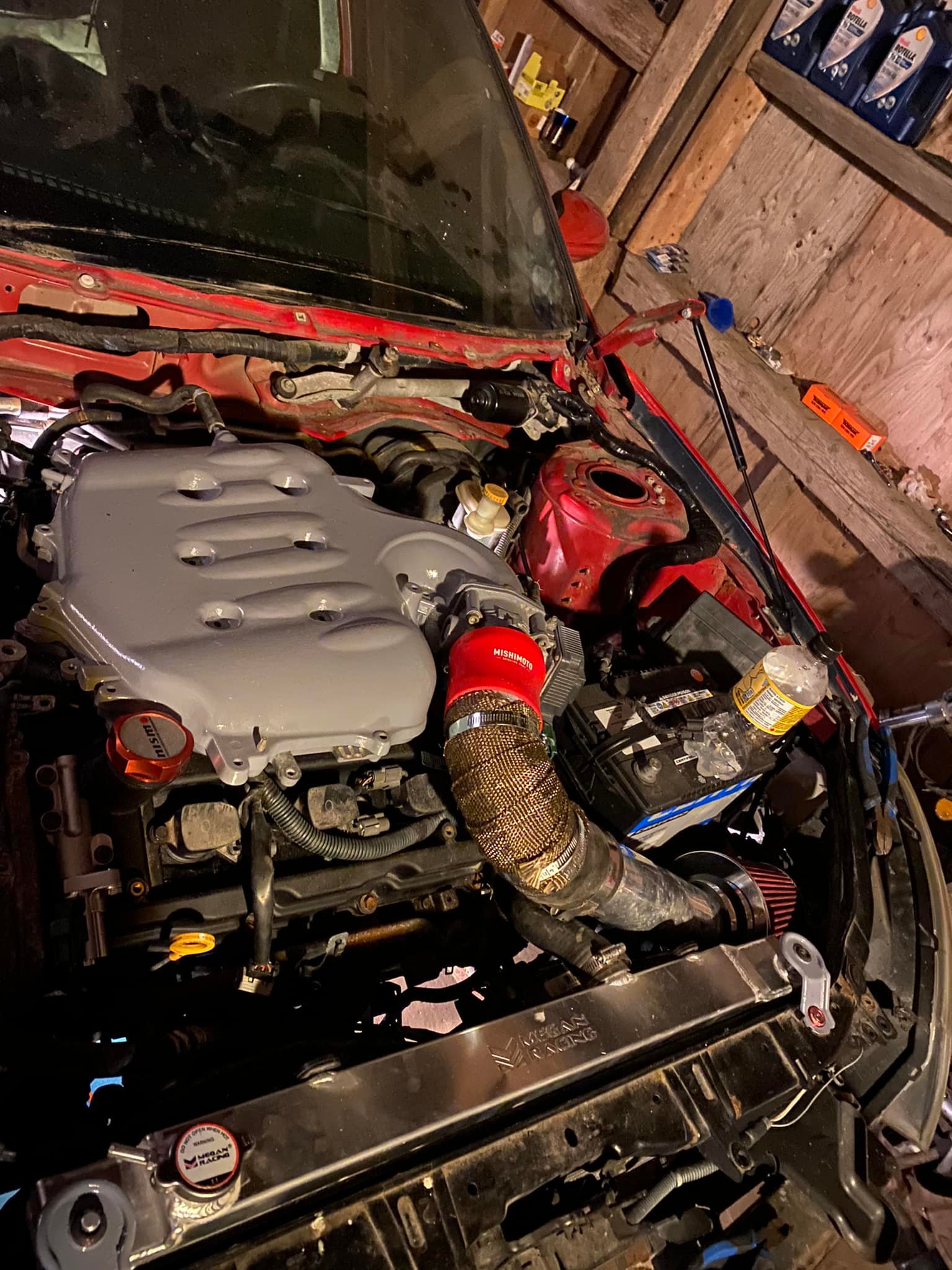
For the radiator hoses I visited a local parts store and asked to get access to all the hoses. The tricky part was the bottom hose, so I found several bends that worked out great. I used a connector to merge the hoses together to make one final piece that would go across the radiator support, to the passenger side, and up like the usual stock hose path. This bottom hose passes directly in front of the feed and down pipes so wrapping them in header wrap was necessary in my opinion to protect the rubber from direct heat.
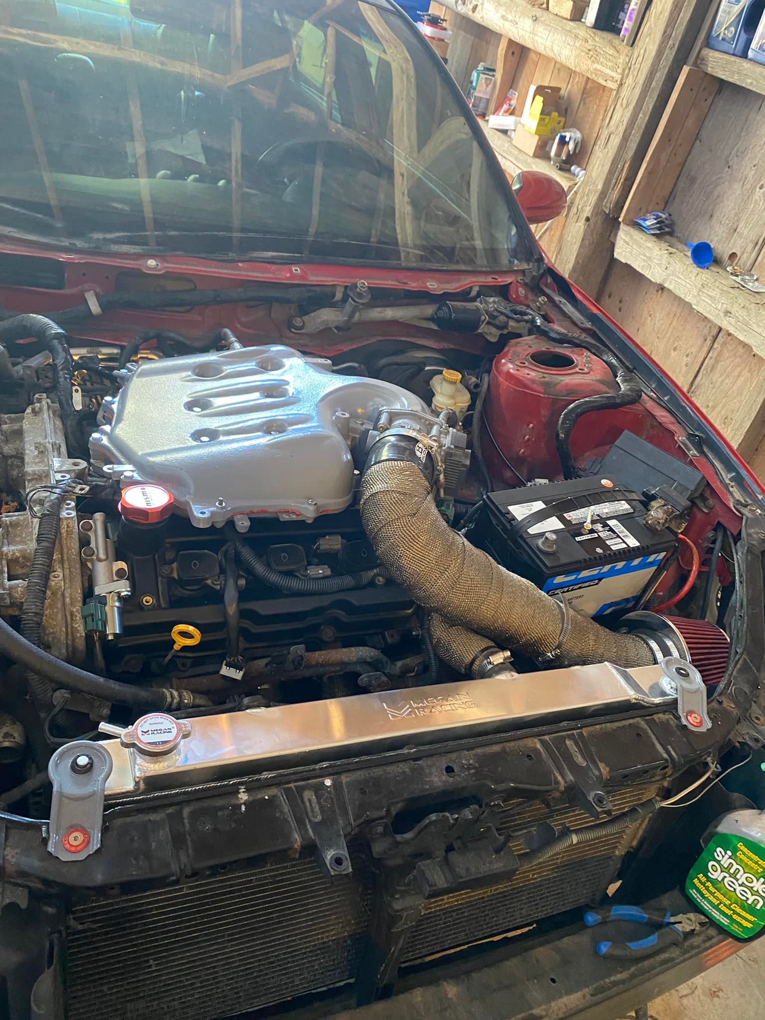
After driving around it was clear that I needed to wrap the down pipe and feed pipe to keep it from starting to over heat; this is when I thought I should have purchased a three core radiator. With a few modifications I have had success with the two core. I created a shield to block the down pipe from radiating heat directly onto the radiators side which helped a lot.
This video shows the heat shield made to block heat from the downpipe.
As you can see in the video, I had the transmission cooler mounted on the grill in front of the turbo. This was an issue because the heat coming off the turbo and exhaust piping would warm up the cooler in traffic. I had to relocate the cooler and at the same time upgraded to a larger unit; more on this in its own blog post.
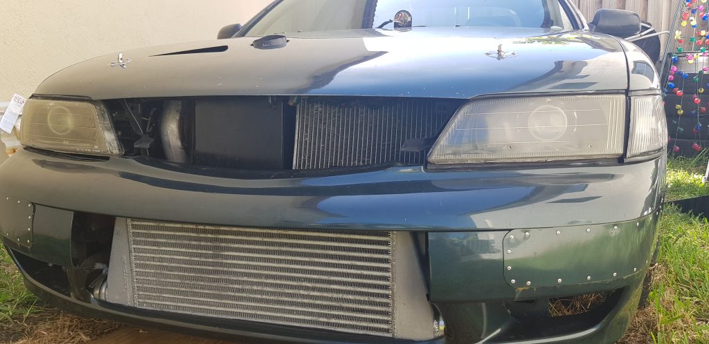
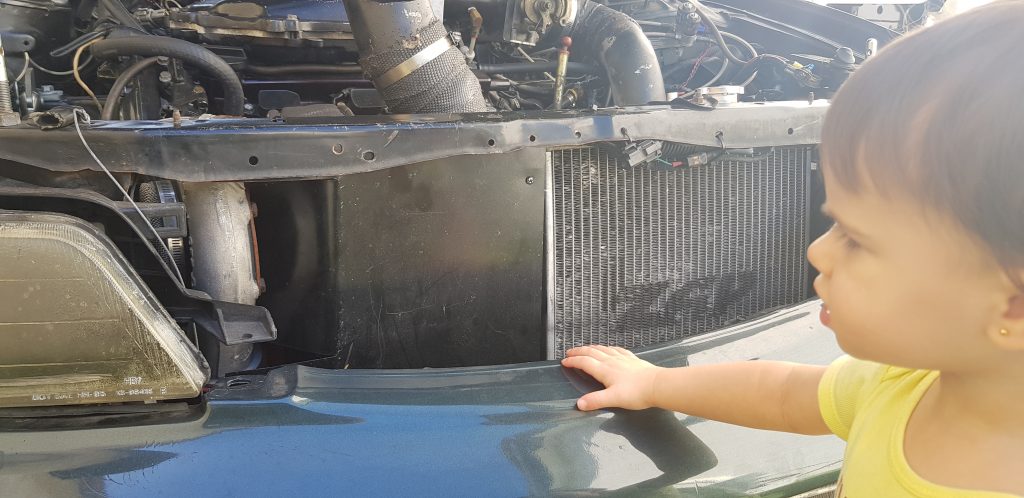
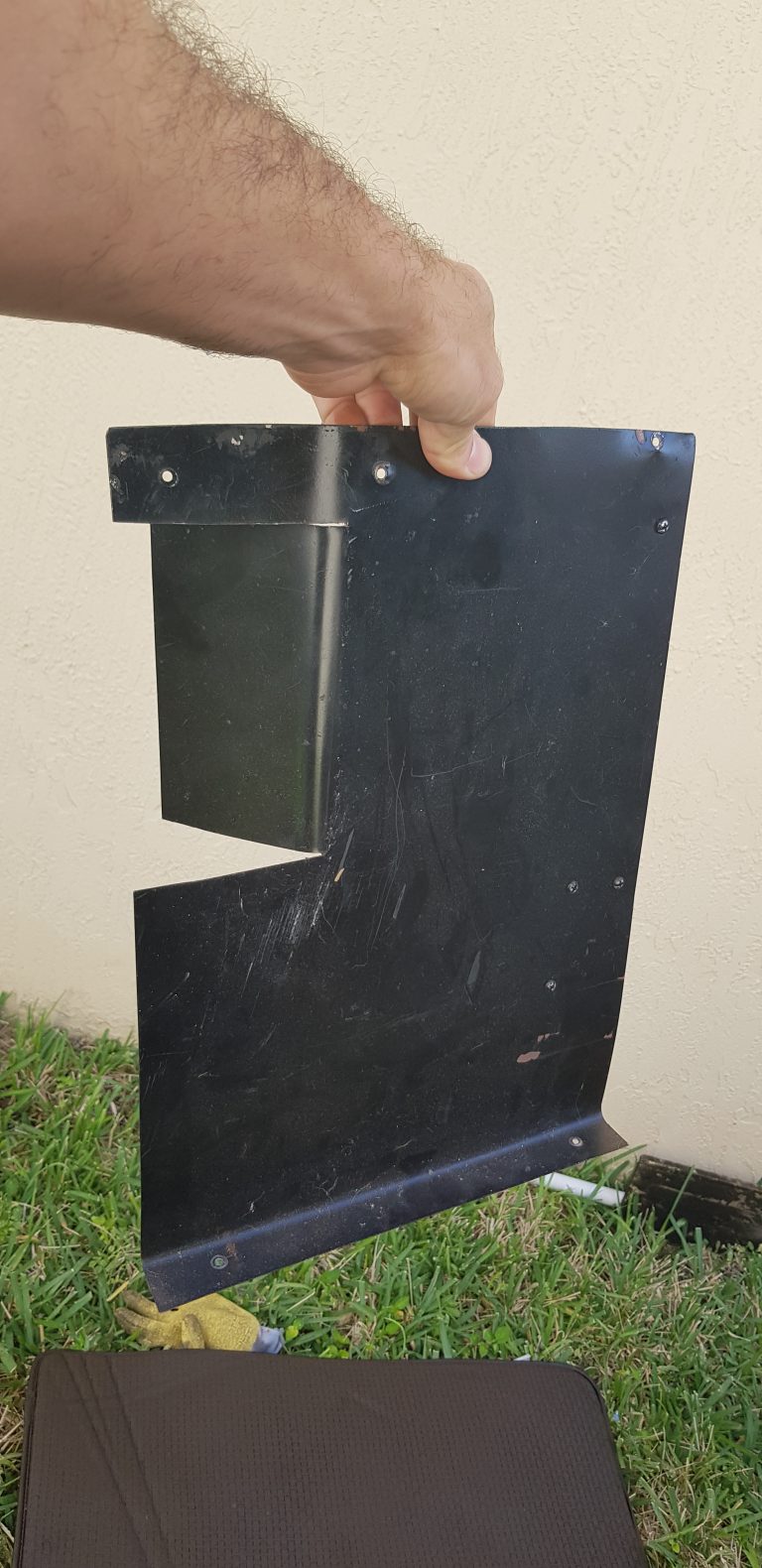
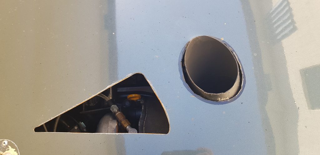
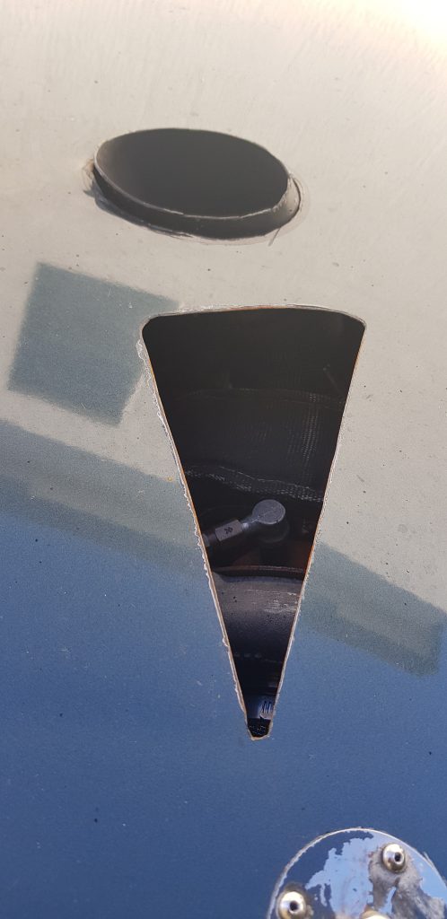
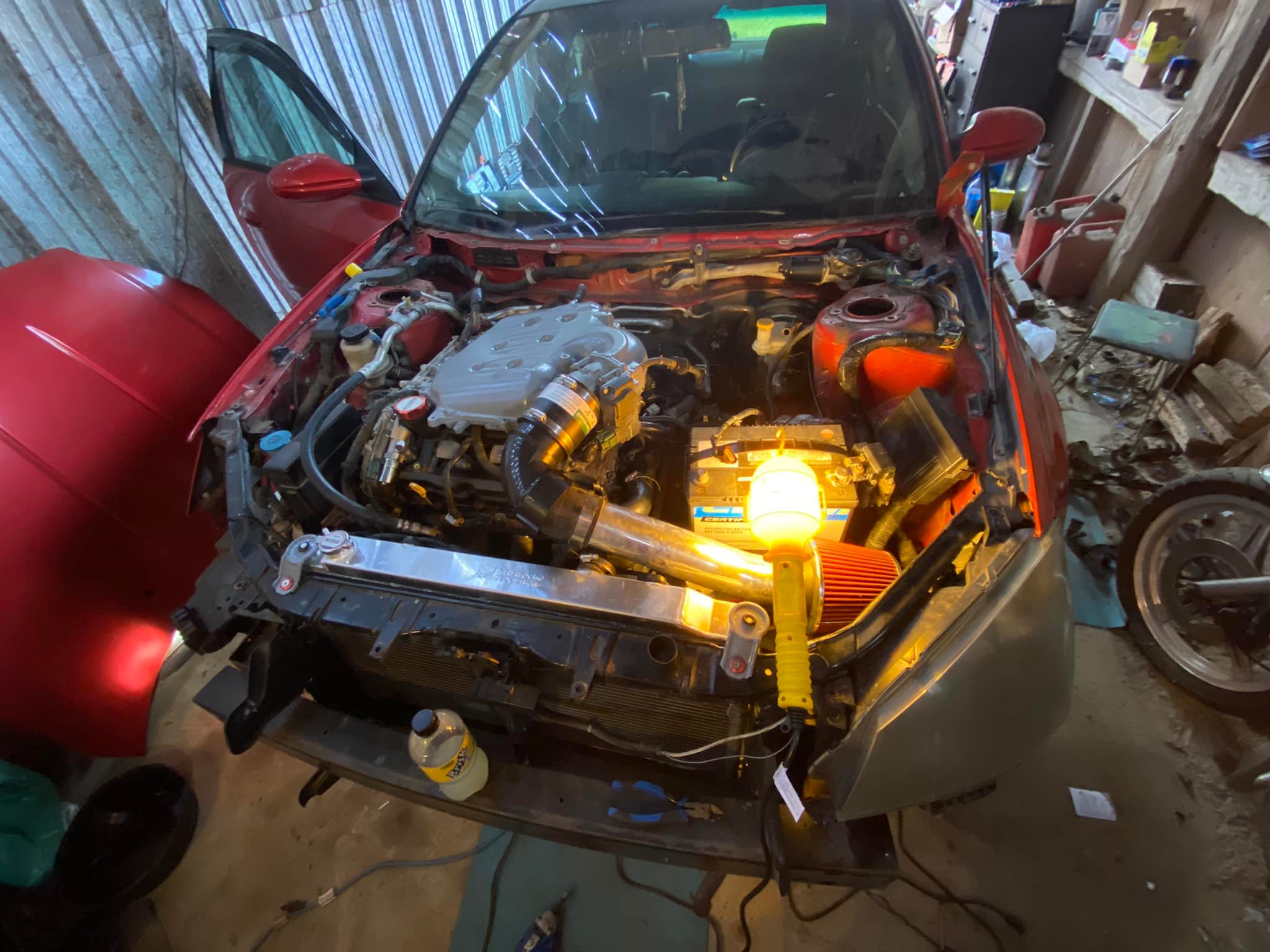
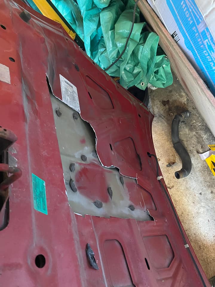
The next test was sitting in traffic or in a staging line. The engine would start to warm up after a long while. I realized that the reason for this was because the passenger side of the grill area was opened exposing the turbo and exhaust piping. This means that when the car is at a stop, heat comes out of the front of the grill area then gets pulled back in through the radiator; basically the radiator was pulling air that was already hot. The solution was to make a plate from thin aluminum which blocked the left side of the grill completely. I then cut a triangle on the hood above the turbo so that it could be an escape for the heat. The end result gave me a reliable setup for cooling.
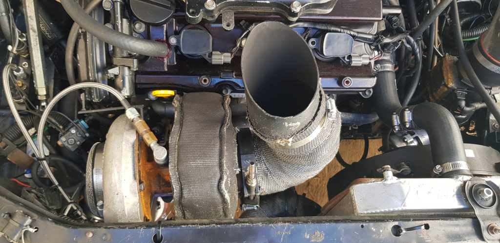
Finally, since the car is now more focused for racing, I created a short exhaust pipe that exits out of the hood. This is used for the track or weekends. Alternately I can attach the catback to the original turbo outlet I created when I want a quiet ride. will go into details in the next post.
In the next post I will go over how I created the rear side exhaust while still keeping a muffler.
In this part three of the front mount turbo setup I go over the exhaust options. Exhaust exit to the floor, exit out of the hood and cat back exhaust.
Some information about the car:
1997 Maxima
VQ35DE
Automatic
Turbo (initially rear mount turbo)
Floor Exit
To get the car on the street quickly I made the turbo exit aiming down to the floor. This was not fun like when you drive around the block with no cat back installed and you cant feel your own body due to the noise and drone. The pipe used was 3.5inch and the bend was made with pie cuts for a sharper turn to stay away from the radiator.
Driving required some getting used too. As you drive a car for a long time you start to become aware of the sounds it makes. You can hear when its lean, rich, knocking, or piston slapping. When those sounds are overpowered by the exhaust, you are left with no feedback; you feel disconnected. Apart from that the car was now alive. Here are videos with the exhaust to the floor.
Front mount turbo idling with down pipe aiming to the floor.
Front mount turbo untuned test drive with down pipe to the floor.
Cat Back
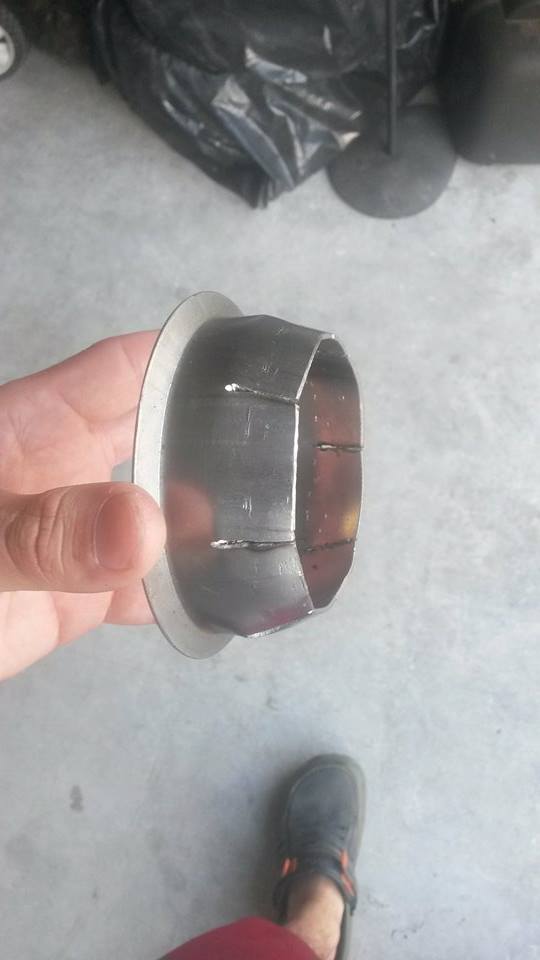
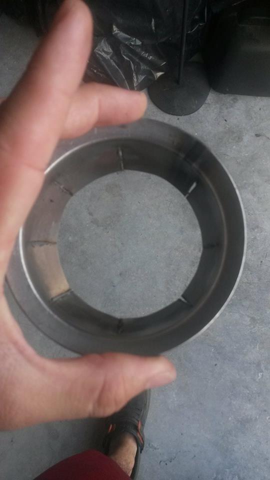
I started working on a cat back solution. There was enough space between the cross member and the turbo feed pipe. I had to make a reducer from the turbo to a 3 inch 90 degree pipe. To accomplish this I got the flange for the turbo and made v cuts all around the end that welds to the exhaust. I then bent the fins(created with the V cuts) inward and welded them all; this gave me a smooth reducer. I welded the 90 degree pipe to the flange, welded the other end to a new 90 degree pipe that turns under the engine and between the cross member and turbo feed pipe.
Testing the cat back exhaust at 16psi of boost.
Hood Exit
The hood exist was not my first option, it was not even a thought. With the car not being daily driven I figured I would try something new. I made a 3.5 inch pipe with pie cuts to achieve 90 degrees and pointed it up to the hood. To find where I needed to cut I put grease on the pipe and closed the hood to see where it would mark. After hacking away this is the result.
The hood exit was more quiet than when pointing to the floor. It is still loud but it does not feel like an earthquake anymore.
In Part 4 of this article I will go over the finishing touches, and that is the side exhaust that sounds great.
To be continued…
Thank you for visiting and be sure to subscribe at the top of the page to get the latest from FastMaximas.
From my experience VQ35’s tend to have excess crank pressure. Think about it, how many 3.5’s do you hear about that are constantly knocking even with 93 octane fuel and nearly stock with little to no modifications. Part reason is because the inside of intake manifold is coated with oil that comes from the valve cover. Oil in the combustion reduces octane and causes buildup. Why are there so many 3.5’s that leak oil; there are even jokes and meme’s about it. Well, to understand let me take the opportunity and go over the PCV system and solutions.
PCV System
The PCV system is a closed system which circulates the crank case pressure into the intake manifold and back into the combustion; the crank case pressure being generated by the combustion.
Inside the engine, the pistons slide up and down on the cylinder. Oil is used to keep the piston from coming in direct contact with the cylinder wall; allowing it to glide and not rub. The pistons have rings around them which have a gap at one end that allows it contract and expand with the pistons. Part of the rings function is to push/squeegee down the oil that is on the walls to not allow it to enter the combustion. During the combustion some of the pressure escapes past the rings and into the crank case. The crank case is the area below the pistons where the crank rotates; the engine block.
The pressure from the crank case needs to escape, so it flows out of the crank case and into the timing cover area. Then it makes its way up to the heads and out of the valve cover via the PCV valve.
The PCV valve is connected to the intake manifold with a vacuum hose. The intake manifold is constantly in vacuum pulling the fumes from the crank case, into the intake, then into the combustion and out of the exhaust.
Problem
It sounds great to pass the wasted vapors from the crank case back into the combustion. The problem is that these vapors contain oil, so the intake manifold, cylinders, and valves all get coated with oil. This turns to gunk and build up which then can cause increase in compression and knocking. Oil in the combustion may also affect the octane level further causing knock; higher compression, less octane, its not a good mix.
Solutions
Vent to Atmosphere
One option is to disconnect the vacuum line that goes to the intake manifold. Plug the intake manifold and leave the PCV open to atmosphere. Now the intake manifold will not be sucking in oil and the crank case still gets to vent. This is not a clean solution as you are venting that into the air we breathe; when it could have been processed through the combustion again.
One thing that you will notice immediately when you vent to the atmosphere is that it will smell bad. It gets in your clothes and in your pores.
Catch Can
The other option is to use a catch can. A catch can is a container which can be in any shape usually as a cylinder or a square aluminum box. When properly designed, this container is intended to remove the oil from the vapors that come out of the crank case.
You connect a hose from the PCV valve into this container. Then you connect a hose from the container into the intake manifold. As fumes are pulled from the crank case they enter the container and pass through turns and walls to help condensate it. The longer the vapors are out of the engine the cooler they get, then the oil particles become denser and stay in the container. Cleaner air exist the container and into the intake manifold.
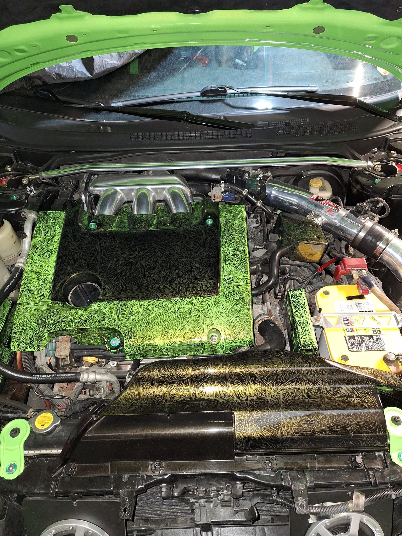
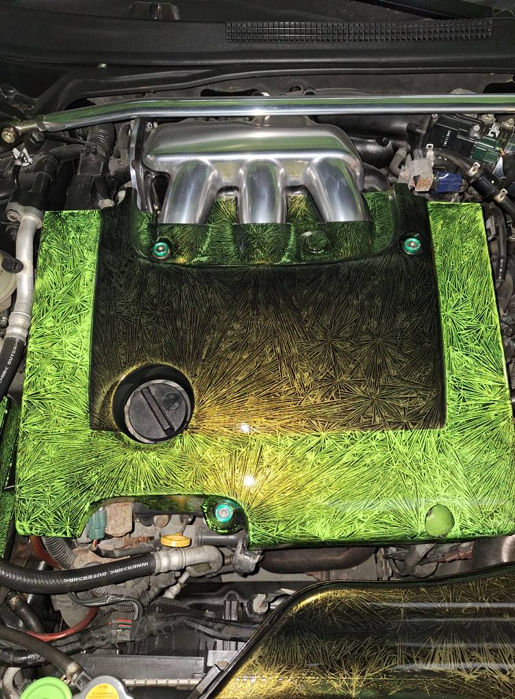
DYI Catch Can
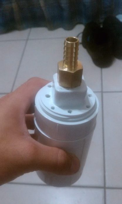
DIY PCV Vented Catch Can with a 1/2 Barb.
A home made catch can can be made using a PVC pipe that is closed in one end and with a screw cap on the other end. You can drill two holes then screw in two brass barbs. You fill the PVC with brillow pads. The purpose for the brillow pad is for the vapor to come in contact with the material and add resistance, condensing it. You screw the cap and you connect the PCV hose from the valve cover into one barb and the other barb is connected to the intake. It works better if the barb that takes in fumes has a hose inside that forces it to travel to the bottom of the container. This way is has to make its way up through the material inside and out of the container; otherwise it will enter and leave the container without barely touching the brillow material.
You can also use a catch can with PCV systems that are vented to atmosphere. A hose goes from the PCV valve to the catch can, then cleaner air exits out to atmosphere (it will smell less and keep the engine bay clean). Usually when you have the crank case vented you will notice your hood develop a film of oil and sometime even coat the whole side of the engine bay. Its not cool when you try to impress a girlfriend with a clean Maxima and smells like you drive a tractor.
Turbo and Superchargers
The PCV valve is a one way valve which allows air to flow out of the valve cover. This helps keep pressure from the intake manifold from going into the valve cover and further increasing the pressure of the crank case. When this occurs you will start to see oil leaks develop. The inner timing cover, the outer edges of the timing cover, the area between the inner timing cover and the valve cover, are all areas that are prone to leak because of excess crankcase pressure.
The problem is that these PCV valves do not seal well against pressure. If you have a turbo or supercharger its likely that the pressure from the intake is going to seep into the crank case. A solution is to put a real one way check valve on the hose. The problem now is, where does the crank pressure go if there is pressure in the intake manifold. Generally it will vent out of the front valve cover where a breather is usually placed on the outlet that often connects to the intake piping near the MAF. This is not enough to vent efficiently, the pressure builds up in the crank case till it finds a way out causing leaks and loss in power. If there is pressure in the crank case it takes more effort for the pistons to go down. You can fix this by putting the line that connects to the PCV valve to the suction side of the supercharger or turbo. This is after it has passed through a catch can; you don’t want your shiny compressor wheel coated in oil.
From my experience, when you start to boost the VQ, you need to also vent out more crank case pressure. You can drill out the PCV Valve and use an external one; you can also replace it with a larger one. If your system is vented to atmosphere then you can drill the valve cover, put a barb and run an additional vacuum hose to the catch can. Some catch cans have multiple inlets. You may also have a filter or breather on the front valve cover while you have the check valve in the PCV hose. When the engine goes into boost, it will close the PCV hose, then vent pressure out of the breather. This is not a good solution as you need more flow than just the breather’s port which usually gets routed to the intake.
One last solutions is to run the hoses from the catch can into the exhaust. The hose connects to a pipe that goes in to the exhaust in an angle in the direction with the exhaust stream. As the exhaust flows it pulls the air from the pipe and the hose sucking the crank case pressure out. The closer you have it to the exist of your exhaust the better because if its too close to the engine usually your exhaust system would have some back pressure. So although it would still work it wont be as effective.
There is another solution which is to use a vacuum pump to pull out the crank case pressure but I will not get into those details in this release.
You should now see if you didn’t already how important it is to deal with the PCV system when you modify your car. It directly affects the power of your engine, yet it tends to get forgotten.
In this article I will be going over all the details involved in the rear mount turbo on my 1997 Nissan Maxima.
Being the first to put a rear mount turbo on a Maxima I had to figure out a lot of things along the way. This article will answer many questions that I have been asked over the years as well as address myths that are generally mentioned. The article is organized in the same way and order that I addressed the project:
Why a Rear Mount?
One day I was watching an episode on TV where they showed an installation for a rear mount turbo on a Corvette. During the episode I started to day dream about the maxima being turbo charged and how easy it looked on TV. I reached out to a friend who had a turbo and injectors collecting dust in the garage and decided to go for it. I was a full time college student with no job so the budget was minimal and I had no resources other than a DIY mentality; this is why the rear mount was attractive. I was clueless on how turbos worked as I had never been involved or even driven a turbo car before; I started to learning all the aspects of a turbo system
How a turbo system works?
Basics
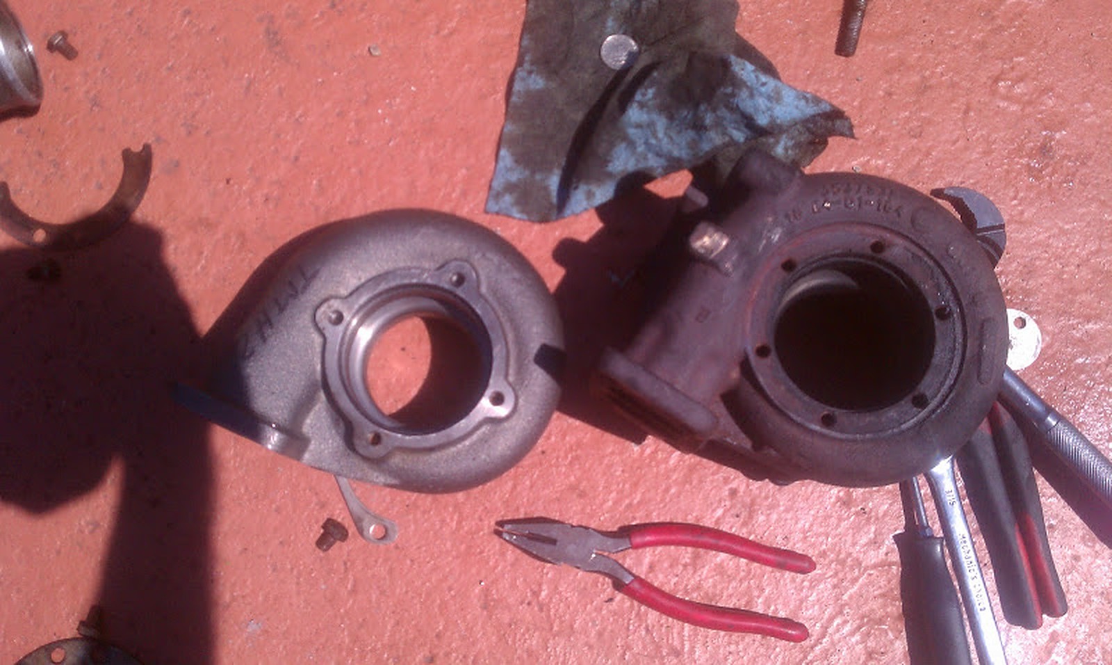
The turbo has three parts, the compressor housing, the turbine housing and the mid section. Both the compressor and turbine have wheels that are connected by a shaft which are held by the mid section. The turbine side connects to the exhaust piping from the engine and as exhaust flows from the engine it makes the turbine wheel spin. The turbine varies in size and dimensions internally and produce a back pressure in the exhaust between it and the engine. The turbine housing also has a variety of flanges with different sizes such as T4, T2 or even a V-band nowadays. This pressure forces the wheel to spin with greater force and velocity. As exhaust flows through the wheel, making it spin, it then exists out of the turbo and out to the atmosphere.
As the compressor wheel spins it pulls in fresh air, compresses the air inside the housing and then exist into piping that is connected to the engines intake manifold. Often the compressed air needs to flow through an intercooler since air becomes hot as it is compressed. The turbine and compressor both have similar designs, an inlet and outlet.
The pressure generated between the turbo and the engine is regulated with a wastegate. Think of the wastegate as a bleed valve that releases pressure in a controlled manner. By controlling the pressure thats flowing into the turbine, you are therefore controlling the pressure being generated by the compressor side that flows into the engine’s intake. The wastegate has a spring inside that keeps a valve closed preventing exhaust pressure from bleeding out. The wastegate’s body is connected to the compressor side of the turbo via a hose, this is usually called the boost/pressure reference. As pressure builds up in the compressor and pressurizes the body of the wastegate, this force pushes against the spring and starts to open the valve.
Wastegate springs vary in size and tension which is what dictates the ultimate boost pressure your turbo system generates. In addition to the spring most systems also have a boost controller. Boost controllers are another form of bleeder valve that regulate how much pressure is begin sent to the wastegate body from the compressor. The less pressure it sees the less force is applied against the spring, therefore keeping the wastegate valve from opening fully to the spring’s force. A simple way to think about it is, when the wastegate valve is fully closed, you generate all the boost the turbo is capable of producing, when the valve is fully open the turbo does not generate any pressure since its all being bled out of the wastegate.
One last piece of a turbo system is the blow off valve. The blow off valve allows for the compressed air to escapes out of the charge piping when the throttle body plate is closed. Without a blow off valve when you close the throttle, the pressure generated will need to go somewhere and therefor will push back out of the compressor wheel. In the long run this can cause damage to the turbo’s bearings and in balance in the shafts spin. So as you build boost, you let off, the air pressure escapes; this is the sound you hear in most turbo cars. Often times there are recirculating valves where the released air is sent back into the inlet of the turbo but I wont get into those details here for simplicity.
Turbo lubrication and cooling
The shaft of the turbo is suspended in the middle by bearings, they can be journal or ball bearing. A journal bearing is when a shaft rotates in a surface that contains oil; the oil keeps the shaft from coming in contact with the surface it sits on. Ball bearing is like a the bearings on a skateboard and requires less oil. There are other technologies such as oilless turbos and different ball bearing materials to but these are the basics and as far as I needed to understand.
When using a journal bearing the volume and pressure of oil applied to the turbo is important and checking with the turbo’s manufacture is always recommended to see what the required volume and pressure is. Ball bearings require less oil so a smaller restrictor is needed than a journal bearing, some journal bearings are said to not require any restrictor but I have never come across this with the VQ; we always need one from my experience.
Another function of the oil is to cool the turbo’s center section; some turbos are also water cooled where they connect to the cooling system of the engine.
The Rear Mount Turbo
Now that we know how a turbo works lets get into the details pertaining to the actual rear mount turbo configuration.
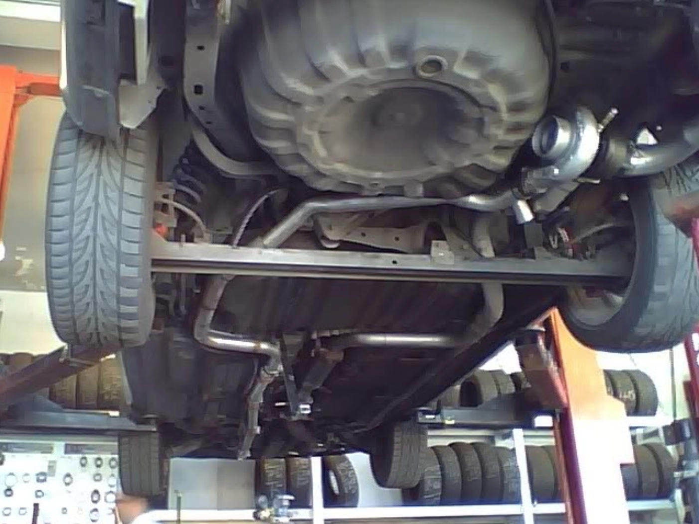
After laying under the car for some times and brainstorming where the turbo should fit best I decided to locate it where the muffler is. I unbolted the muffler and cut off right after the rear beam, then had a local muffler shop weld a T4 flange using the turbo to mock up. Once I was home, I then bolted up the turbo.
Rear mount turbo maxima no muffler.
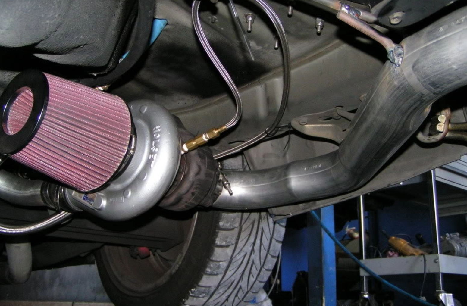
The turbo air filter I used was a large 4inch open K&N. I had to hammer in the spare tire well so that the filter could fit however that is not necessary as there are filters that have a much lower profile. I had a few ideas for locating the filter including having it inside the truck, or routing it to the driver side. I tested putting the filter in the trunk while having an additional hole for fresh air to come in. The hole I made for the fresh air to come in was not large enough so with the windows closed when the turbo would go into full boost you could feel the negative pressure in the cabin; not good. At the end I kept the filter like shown in the picture for years and never did I have issues with water. This car was driven daily in Miami where it is raining often.
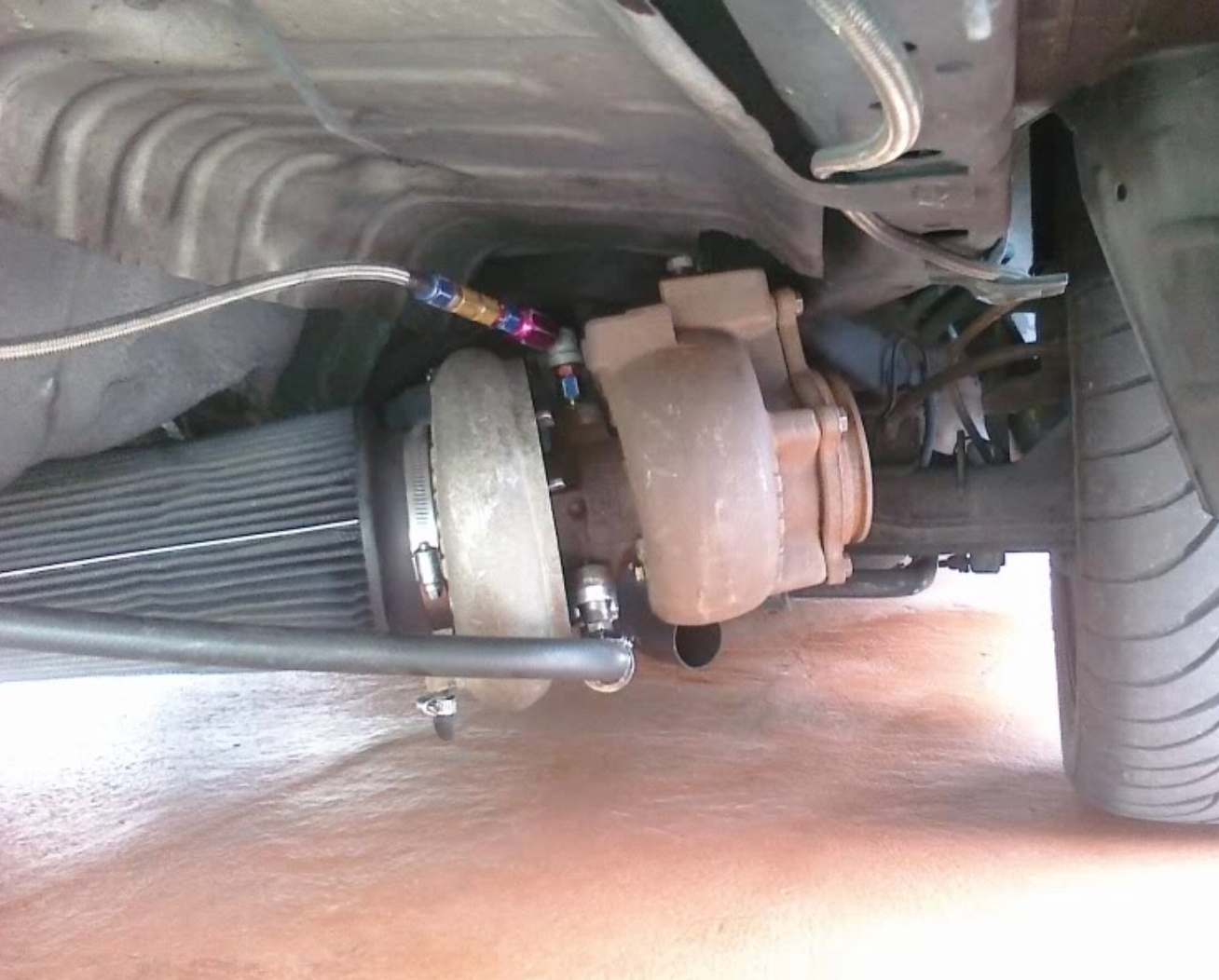
Oiling the turbo in the back.
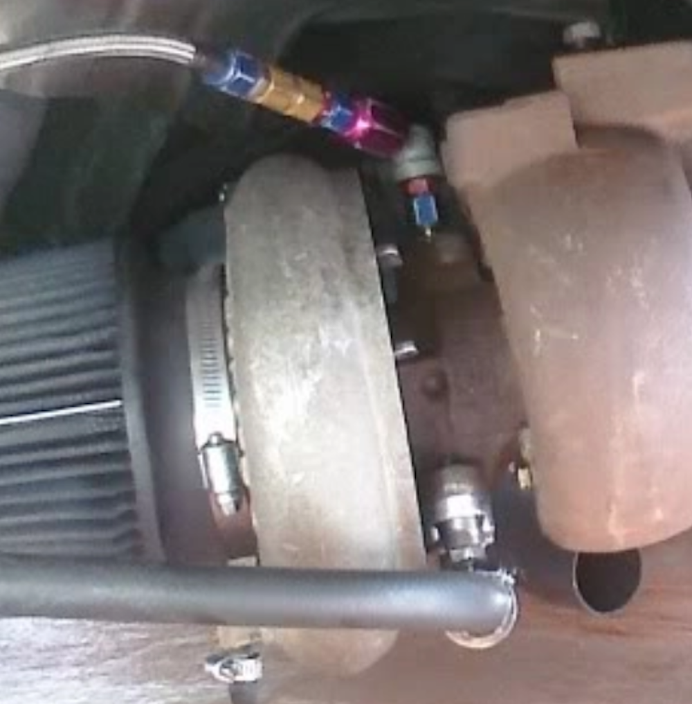
I purchased a generic eBay sandwich plate that has 4an ports, added a 4an fitting and then connected a nitrous line (what I had at the time). I routed the line on the passenger side of the bottom of the car using zip ties to hold in place.
Sandwich plate(blue) for turbo’s oil feed and oil cooler plate.
On a traditional front mount turbo setup the oil feeds the same way, but the drain or outlet of the oil from the turbo goes back into the engine via gravity; most front mount turbo’s are located above the engines upper oil pan. Since I did not have this possibility I needed to figure out how to get the oil from the turbo back to the engine.
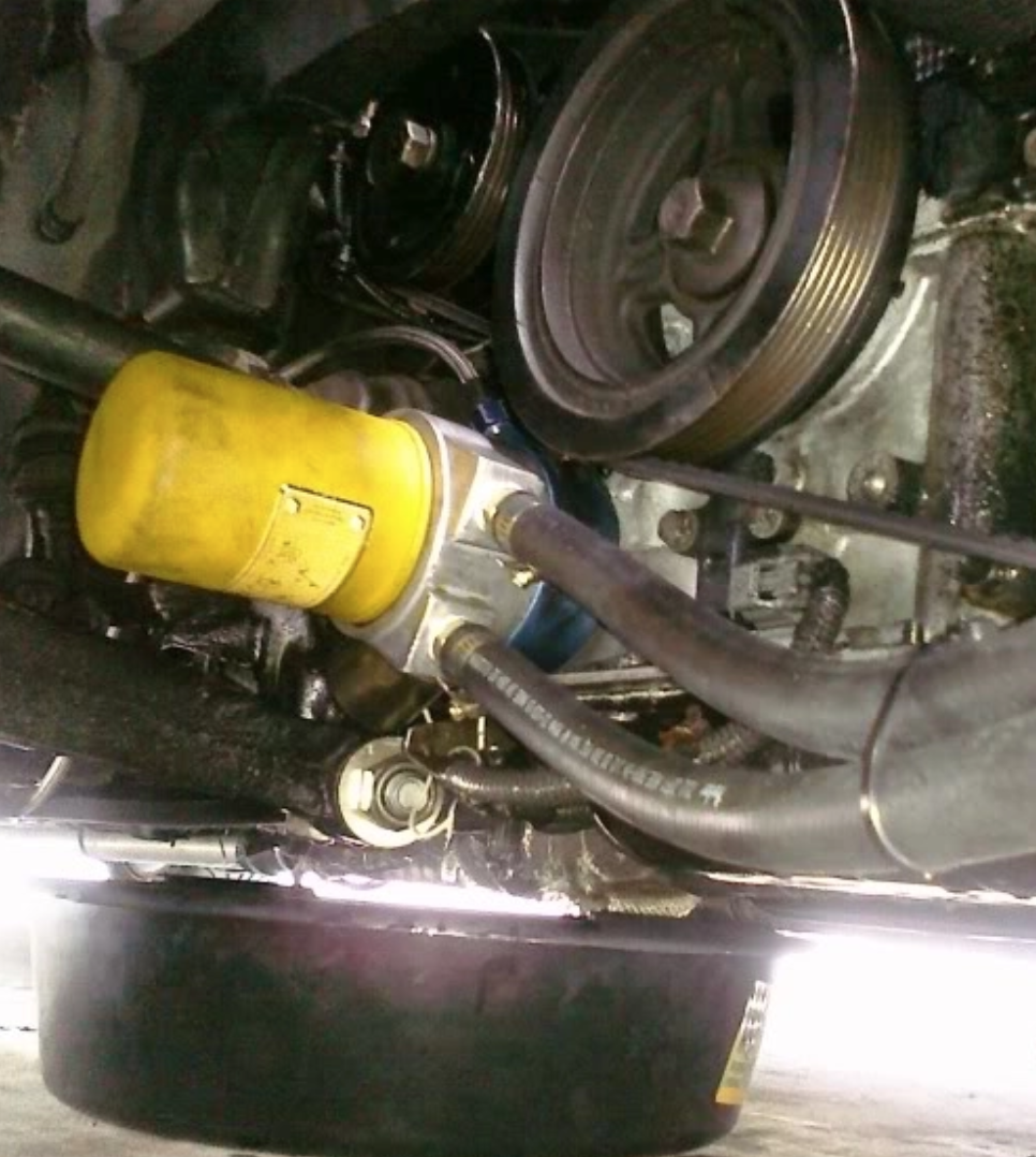
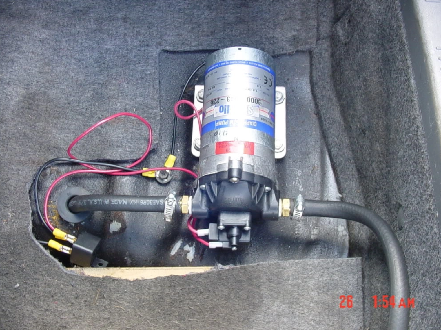
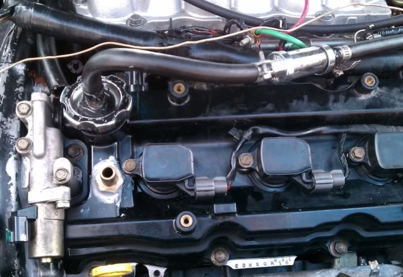
My solution was using a Shurflo 8000 series scavenge pump that is generally used for water, such as in RV’s for sinks or other uses. I decided to use this after having long conversations with someone in the Cavalier Z24 community that was also working on a rear mount turbo. I used an 8an line that connected from the turbo, into the trunk (by the spare tire well) and into the pump. The pump outlet had a 3/8th hose that came out of the trunk by the driver side of the car, over the rear beam and to the front of the car beside the fuel line. At the front of the car the line then came up over the transmission toward the front valve cover and then to the oil cap. I bought a metal oil cap then I drilled, tapped and screwed in a 3/8th barb which is where I connected the hose. I also had a clear glass inline fuel filter without the insides so that I can observe the oil flow for testing and diagnosis.
Scavenge pump for turboOil return from turbo
Oil problems
Oiling was the most challenging part of this project because I had to deal with regulating the flow going to the turbo in coordination with how well the pump removed oil from it. If you feed it too much oil, the pump may not be able to pull it fast enough so then the oil builds up pressure in the mid section and leaks out of the turbine housings. I quickly learned that blue smoke on vehicles usually means that oil is being burnt (white smoke being coolant, black smoke being fuel).
Part solution was using an oil restrictor. These restrictors are sold specifically for turbos but being on a budget I had to work with what I had, and that was using nitrous parts. For the Garrett T04b, I used 4an fitting, cut off the flared part that connects to the hose and put a nitrous jet in its place where I then drilled a 1/16th hole; this gives you an orifice size of 0.063.
This helped stopped the turbo from smoking and i was finally able to drive around with it but there were more complications.
I noticed that when the car was at a stop and then I started her up, smoke would come out again. The reason was that while the car was turned off, the feed line to the turbo continued to drip oil into the turbos mid section and then leaked into the housings. I fixed this by putting a check valve that required 1psi of pressure to allow fluid to pass, with the car off it no longer leaked.
Another issue was that even with the pressure check valve in place it would smoke. The reason for this was because the pump was wired into the ignition. So when you turn off the car, the pump does not have time to pull all the oil collected in the line and turbo; this causes it to leak into the housings. The solution was to leave the pump running on a turbo timer for a few seconds to clear out the line. I used a generic eBay turbo timer for this.
The last problem I had was when doing long highway runs where the engine was at high RPM’s for an extended period of time (for example a 1/4 run) the pump was not able to keep up with the oil delivery. I ended up adding a second pump using a T on the line for pulling from the turbo and another T on the line that went to the front of the car. This was the last step needed to not have any oil issues again. This process was all through discovery by trial and error so doing this again would be very simple.
Turbo Charge Pipe
Initially the turbo charge pipe size used was 2 inches. It was out of steel as it was the quickest and cheapest option available for me. For bends I used heater hoses and worm gear clamps. I routed the pipe from the turbo to a 90 degree turn towards the drive side, then a U bend over the beam and towards the bottom of the gas tank. From the gas tank I ran a straight pipe beside the fuel lines and oil line to under the transmission, then a 90 degree turn up where the blow off valve was placed, then another 90 degree turn that routed towards the intake manifold. This initial setup was without an intercooler and the initial boost pressure I went with was 6psi.
Intercooler
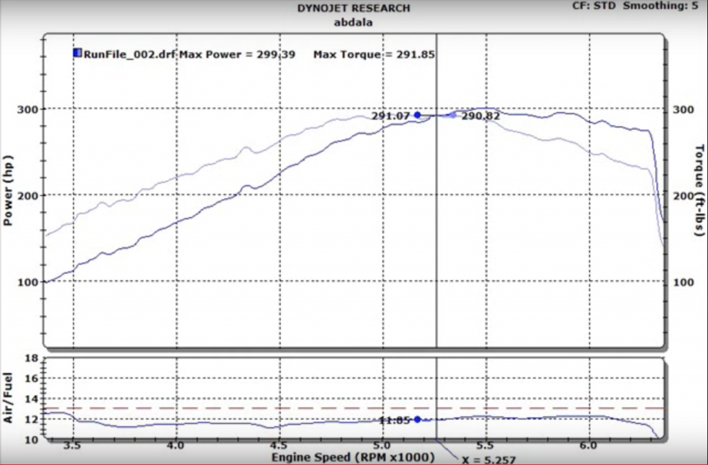
At first, I did not use an intercooler for simplicity. Eventually I purchased a methanol and water injection kit (there will be another article about this) because I quickly started to pick up engine knock. There is this common misconception that by having a turbo mounted in the rear, you no longer need an intercooler; this my friends is completely false. I was able to push the system without an intercooler up to about 10psi with the methanol and water injection. Without the intercooler at 10psi I achieved 299whp and 291wtq, at 6psi it made 250whp and 242wtq.
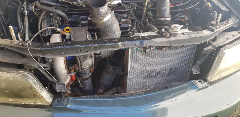
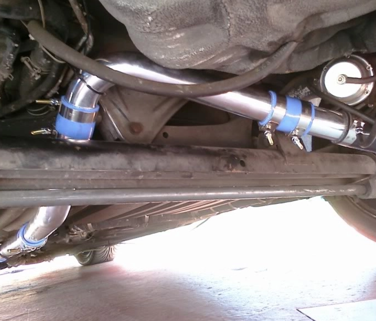
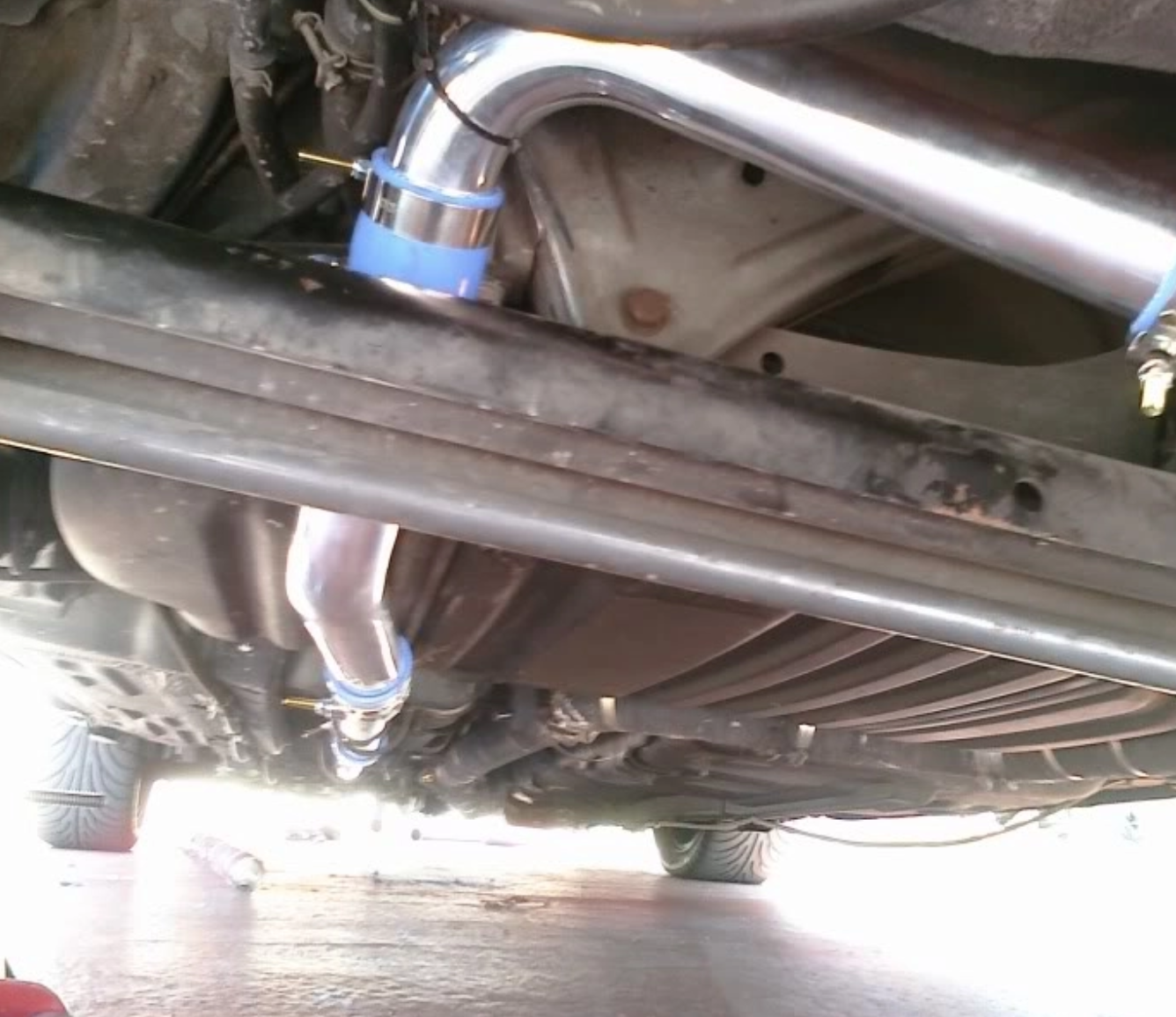
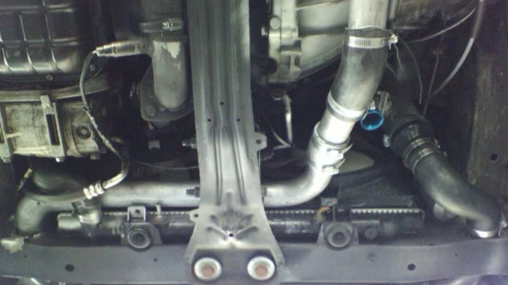
I routed the charge pipe from the turbo by going under the transmission, then a bend that turned towards the passenger and between the radiator and the front engine mount. Then the pipe continued to near the fog light area where it turned towards the radiator support and through it (after drilling a hole through the support). Then a bend into the intercooler and on the driver side the pipe exited and turned into the support back towards the engine bay. Then the pipe turns upwards with the blow off valve in place behind the fans and then towards the MAF and throttle body.
Rear mount turbo manual maxima intercooler piping.
I then upgraded to an intercooler with the size of 28X5.5X2.5 and the inlet/outlet were 2 inch. My temperatures before the intercooler on average were 130’s F during boost. After the intercooler installation the highest temperature I saw was 111 F. This was on typical Miami summer weather so likely in the low 90s or 80s.
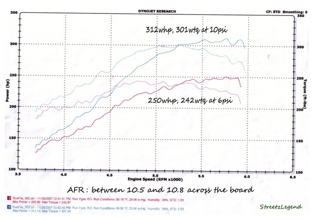
With the intercooler, I at the same 10psi it made 312whp and 301wtq.
T04b 10psi and 6psi Dyno, non-intercooled meth/water injectionT04b 10psi and 6psi Dyno, intercooled meth/water injection
Upgrading to 2.5 inch Charge pipe
Over time I felt that the 2 inch charge piping was a limitation, so I purchased an intercooler piping kit from eBay for 2.5 inch diameter. I then pressed them into an oval with 2/4 pieces of wood and a mallet. This was the pipes that went directly under the car between the gas tank and the engine.
The performance gains from upgrading to 2.5 inch was drastic in all aspects. Spool up was faster, the mid and top end of the RPM performance were significantly improved. The 2 inch piping which I believed would have improved spool up due to more velocity was actually a big restriction. I recommend starting off with a 2.5 inch charge pipe from the beginning.
Exhaust Piping and Spool Up
From the engine to the turbo I already had a 2.5 inch y-pipe and a 2.5 inch cat back. One of the most important parts of the whole system as far turbo performance and response goes was to wrap the entire exhaust with header wrap. I wrapped the y-pipe and the cat back; this improved the spool up of the turbo. The next improvement was removing a 22 inch Magnaflow resonator. I found that even though the resonator was completely straight through, it slowed spooled up by a lot. This could be because the resonator could have been functioning as a heat sink absorbing a lot of heat and therefore slowing down the velocity of the exhaust. With the piping wrapped and no resonator the turbo responded just like it would on a front mount, at the time I had no way of logging so I did not record data for this, but it was a significant improvement.
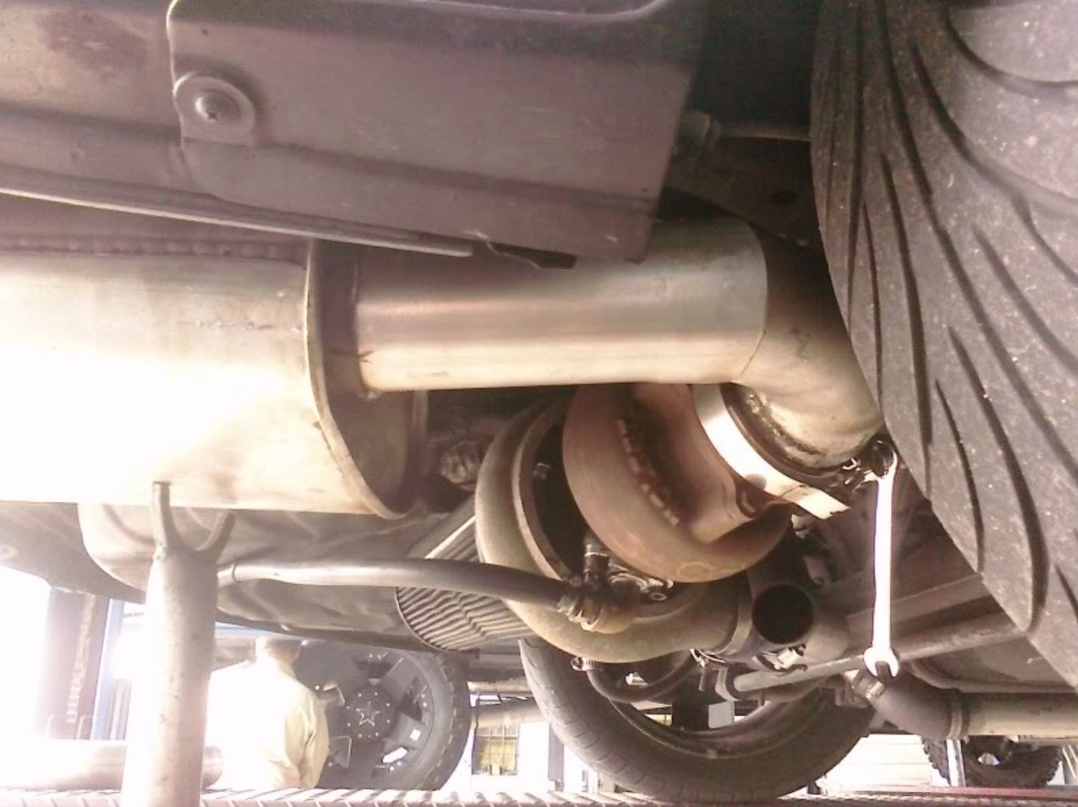
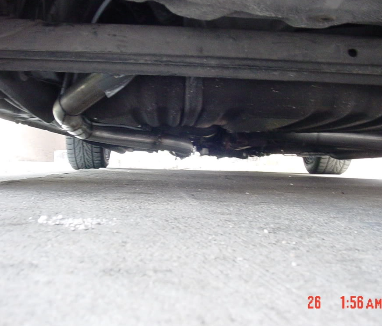
I then had the muffler shop route a straight pipe from the turbo to the factory muffler tip location. This picture below shows another rear mount turbo maxima where the same straight pipe was done.
The next step was to figure out what to do about the sound, it was very loud and being automatic it did not make for a good daily driver like this. I went to the local muffler shop where they put on a bend out of the turbo near the tire, then into a muffler. At first the bend was crushed style but we all know this is not acceptable so eventually I upgraded to a mandrel bent outlet.
I now had a turbo rear mount maxima that was quiet and performed really well. I drove this car for years with this setup and raced it a lot. Here are additional photos showing how one can route the piping on the 4th gen Maxima.
First 1/4 Track Time as a Rear Mount Turbo
With the TO4B turbo, boosting 7.5psi non-intercooled, a 2000-2001 Maxima intake manifold, and an APEXI VAFC2 for tuning the fuel, this is what the car ran in the 1/4 mile.
My previous best time was with the 75 nitrous shot and I ran a 14.2@98mph with a 2.3 60′. The turbo at 7.5psi was putting down more power than the 75shot.
In the next article I will continue to discuss the rear mount. I will write about a different solution for the oil system among more details regarding the rear mount. Thank you for reading and feel free to comment or ask questions that were not covered so far.
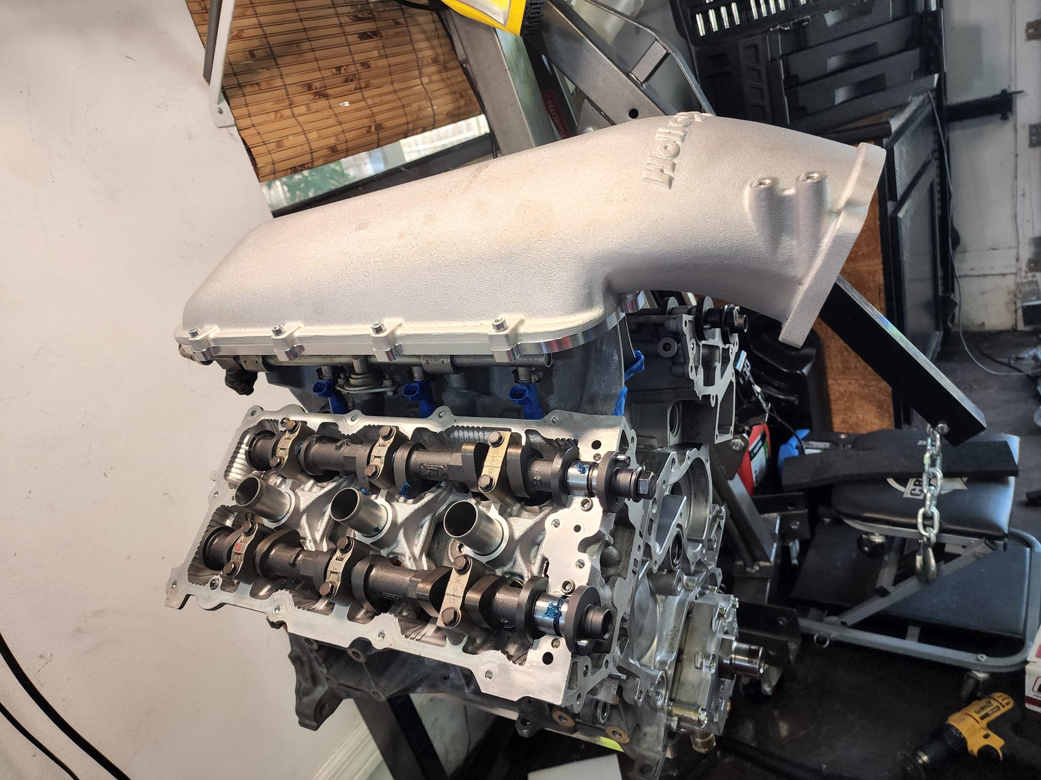
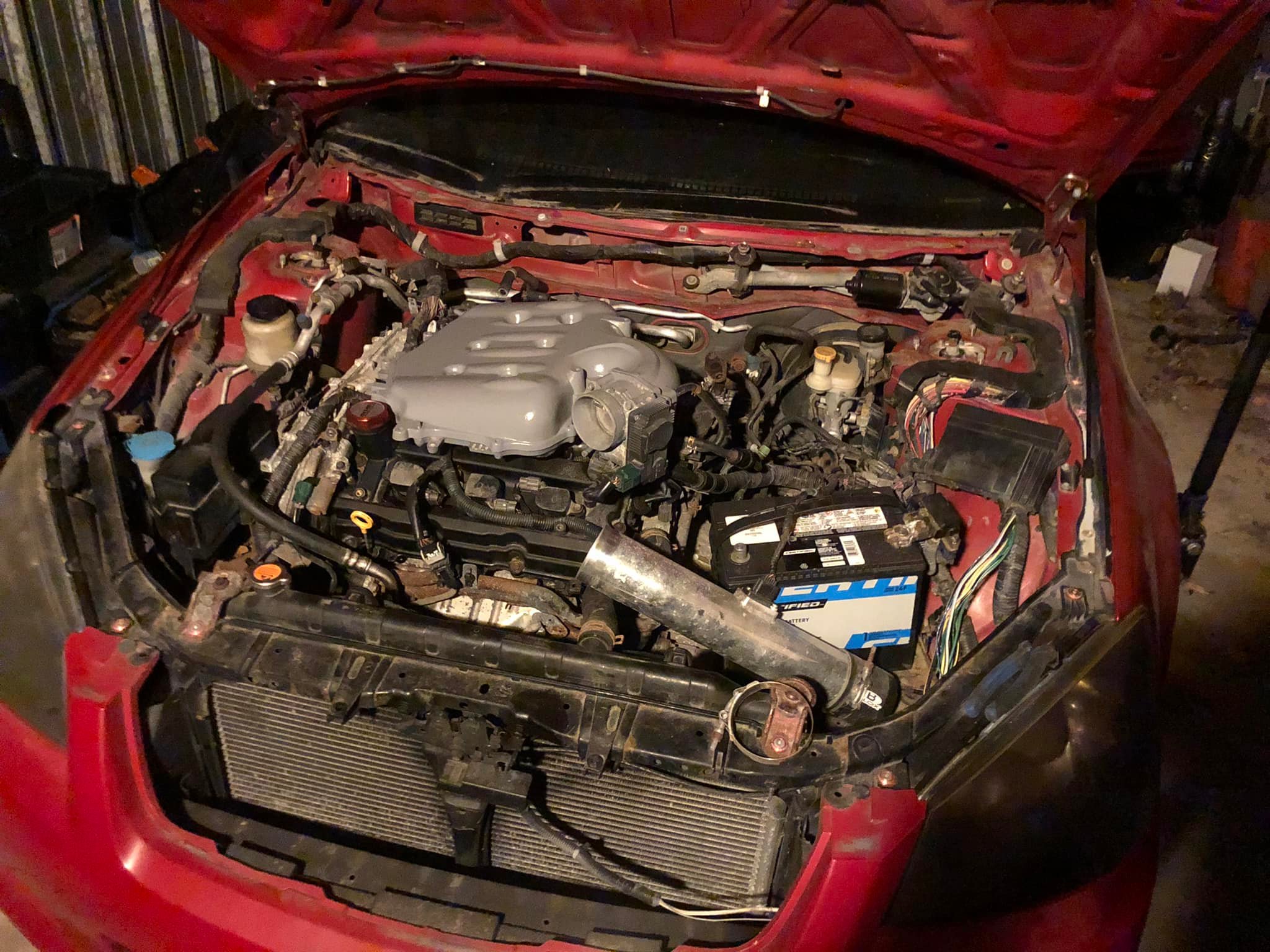
Rear Mount Turbo VQ35 Swap
After racing the VQ30 a lot I eventually needed to replace the head gasket. Since this was my first experience tuning a car, the engine spent a lot of time knocking initially. I wrote an article about my tuning experience here. Over time I noticed that at 10psi the coolant reservoir would over fill, this meant that the head gasket was starting to fail. I then replaced the gasket and continued pushing the VQ30 passed 10psi. The engine started to also develop additional blow-by because the rings were not sealing properly. I believe these failures were due to my tuning experience, I am not upset nor do I regret this as this was part of the learning experience for tuning a turbo car.
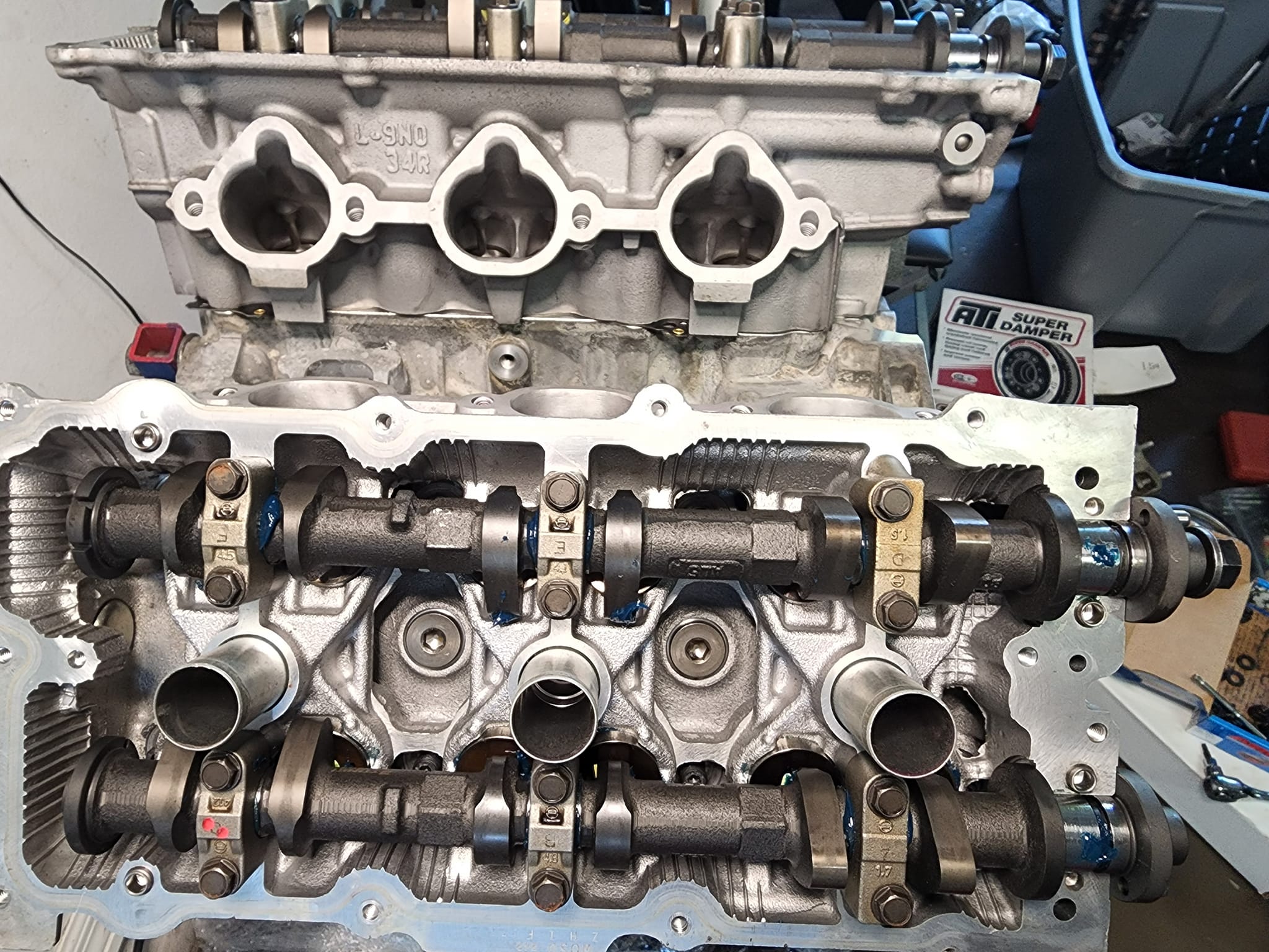
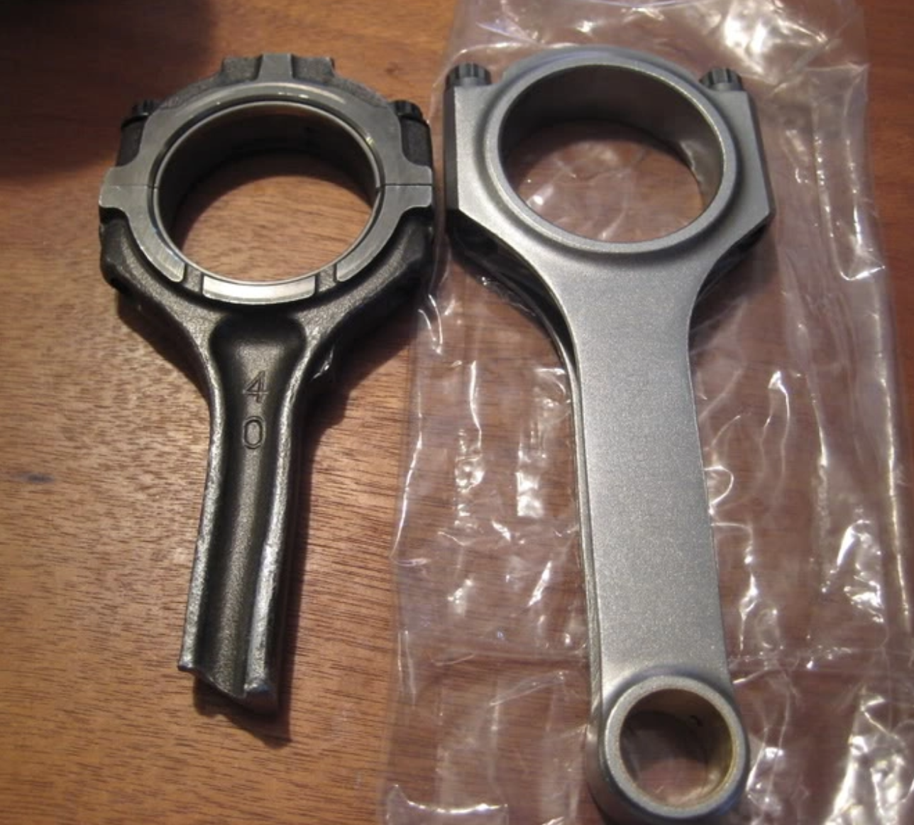
I then did the VQ35 swap while using the 3.0 timing equipment. The engine I used was from the junk yard and only lasted about two weeks before a rod broke. When I finished the swap I always noticed a feint tapping sound and VQ’s being noisy engines I somewhat ignored it but still acknowledged it (maybe I was in denial). Then while cruising down the highway without putting it through any abuse the tapping turned into a loud knock which eventually went silent. The moment it went silent I knew something was about to happen and then BAM, a rod broke. This is why I will never trust a junk yard VQ engine, specially since we are seeing blow VQ35’s being a trend now when put under some significant boost. My decision was to build the bottom end of the VQ35.I will write an article about it because it was a fun journey where I learned a lot and I know many of you will find it valuable.
Most of the videos I have as well as races at the track as a rear mount turbo were all with the built VQ35.
Stock VQ35DE Broken Rod compared to an Eagle H-Beam Rod
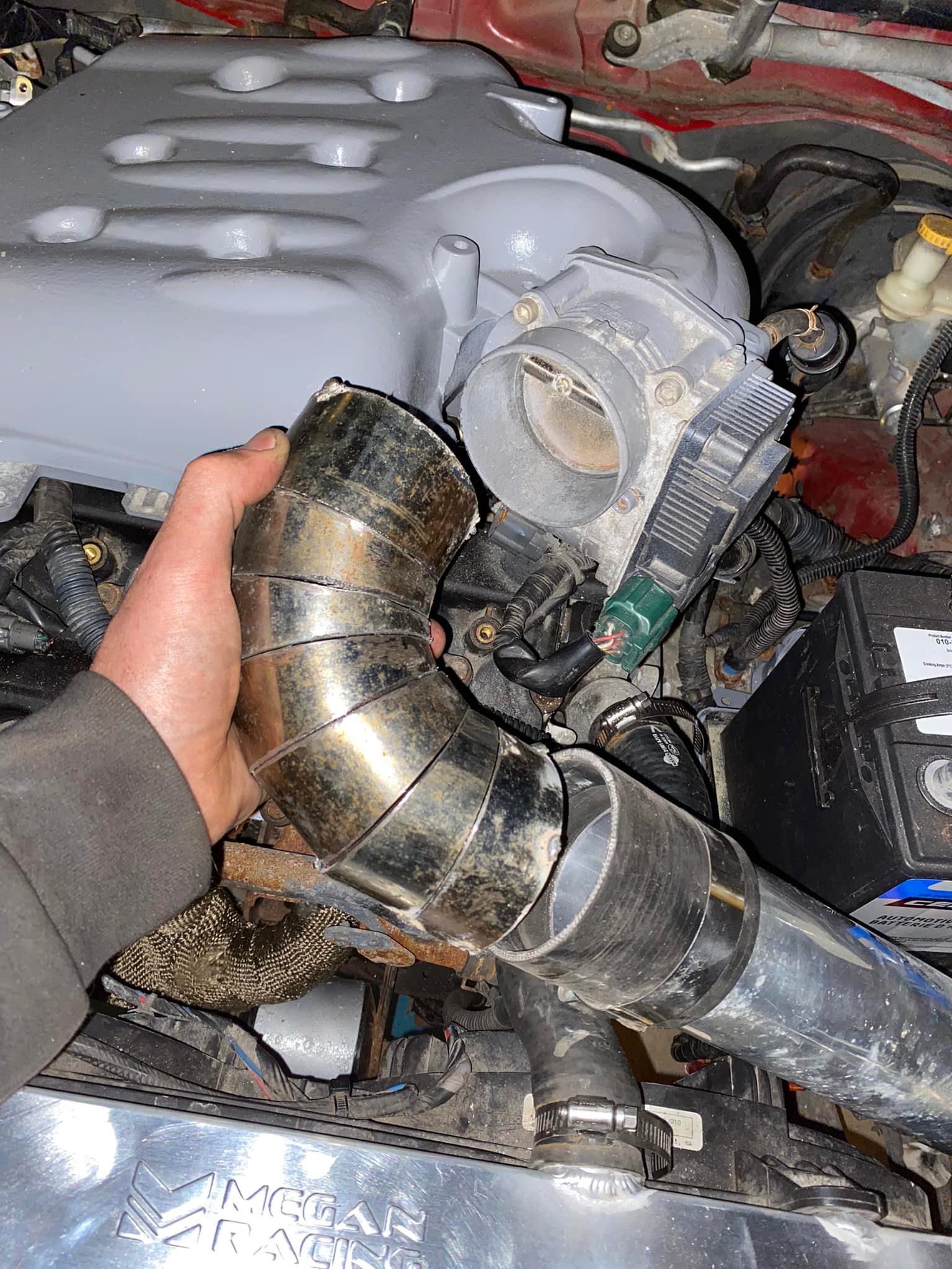
Turbo Compressor Surge
Something I experienced was what they call surge (flutter, among many other names). That is when you let off the gas, the throttle closes, and the pressure does not escape out of the charge pipe fast enough causing the pressure to back up into the turbo compressor wheel. The sound produced to some may be cool, but it is not good for the turbo, some turbos are designed to handle this but its better to not have this at all. This cause throw off the balance of the wheel and shaft. The blow off valve that I had was not able to vent enough so when I would let off you could hear the flutter (sh sh sh sh sh sh). I am not going to lie, I loved the sound. What I did was add a second blow off valve to the back near the turbo, then a hard line coming from the valve to the intake manifold. Now when I let off the gas, both blow off valves open venting the charge pipe immediately.
I also learned that it was important for the blow off valves to have a good source of vacuum, and having a line that would not flex or collapse. This way the response and volume pulling the valve open would be greater. A thin line with vacuum is far weaker than a large line with vacuum.
Self contained oil system for the rear mount
One thought I had was to have a self contained oil system for the turbo. This is when the turbo oil is fed from a tank through a pump. The pump pulls oil from a tank, sends it to the turbo, the turbo then drains the oil back into the tank. I spent a lot of time thinking and planning this out but at the end of the day, it was not worth the effort. You have to take care of cooling the oil because with every pass it gets through the turbo it is heated. You also had to possibly vent the tank.
Now the tank or container can be below the turbo so that the drain naturally flows into it, but being a rear mount turbo means that the turbo is already pretty low unless you have it way up in the bottom of the car. This means you would need two pumps, one to pull oil from the turbo and feed it into the tank, and another to send the oil back to the turbo. Now you have to take care of the pressure being sent to the pump and regulate it. All this was too much trouble to really have little benefit in my opinion. Having a line from the engine to the turbo, then a line from the scavenge pump to the engine was far simpler and effective; possibly even cooling the oil on the way back (although I didn’t do it with this intent).
What are the costs involved?
A turbo can be had for any price to be honest. I started off with a hand me down which was a T04b T4 .69ar turbine turbo. Then I got a genuine Holset HX35 for less than $300, and eventually ended up with a Holset HX40Pro Replica for also less than $300. I put a lot of miles through these turbos, over 100k miles on the first engine build and the only issue they had was due to user error when I made a mistake that caused the oil feed to be restricted, running the turbo dry. Here is what that sounded like:
And this was the damage:
I mention this failure in this section because once you turbocharge a car, you will have issues come up, specially if it is the first turbo system you have worked with. So yes you can have an initial parts list all priced out but you also have to think about what could come up later on. Now lets get into the parts list.
Parts List
The parts list would be the same as a front mount turbo.
Turbo ($300-$2000)
Wastegate ($250-350): I did not want to go cheap on the wastegate as it is an important piece, I got a Tial 38mm.
Blow off valve ($25-$200): this I did go cheap with and I used an Turbo XS RFL which was very loud and fun to have, however by design they leak since they do not have a diaphragm, its a metal piston that does not seal completely.
Scavenge Pump ($100-$200): I used a Shurflo 800 series pump, two of them. A gear driven pump is said to be better for this occasions, those go for about $400-$600 at the time I was looking. ebay has them nowadays for less than $100 but I have no experience with them.
Intercooler ($100-$300): I started off with an eBay intercooler, then upgraded to a better quality one.
Oil Sandwich Plate ($10-$30)
Stainless Steel Braided Oil line ($20-50): I used a 4an nitrous line.
3/8th oil line (transmission line works): This line is for returning oil to the engine as well as pulling from the turbo and into the pump.
Charge pipe ($80-200), that can vary greatly depending on how you go about routing and material.
The rest is miscellaneous parts and labor such as welding, flanges, gaskets, etc…
Turbo sizing specific to the rear mount
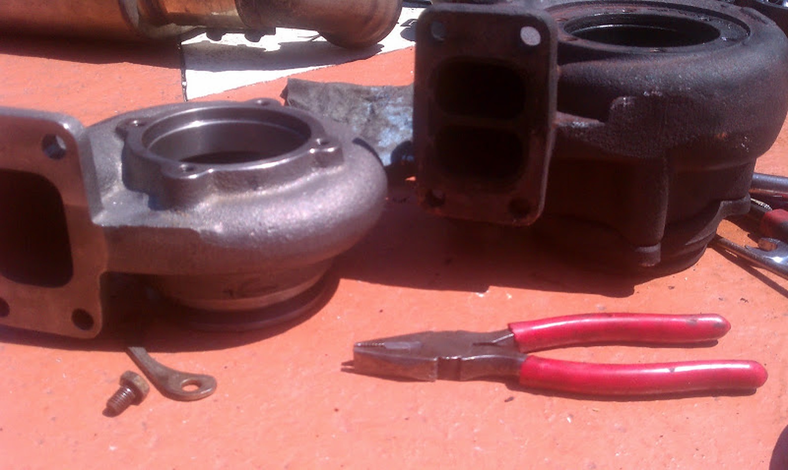
After using the T04b turbo, I then moved to a Holset HX35 turbo. I did research on the Holset’s and saw that one of my favorite platforms (the DSM’s) used them a lot. I got on eBay and came across a brand new genuine unit for about $235, I had to get it.
The HX35’s are ideal for mid 300whp, once I wanted to make more power I went for an HX40Pro. The Pro means it has a larger more efficient compressor wheel that helps produce more power. These turbos come with a large turbine housing with over 1. AR (18cm^2). They do not spool very fast but work great overall. I saw that the DSM community likes to put a T3 .70AR Bullseye turbine, now this my friends really transformed the performance of the car; the turbo spooled immediately.
This is how the turbo performed with the large Holset 18cm housing before the Bullseye housing.
This was my reaction on the maxima forum after putting the Bullseye .70ar housing: “Got the .70AR housing installed and HOLY F***. I can get full boost in 1st gear (15psi, even with no load while spinning lol). in 2nd and 3rd boost comes in like if it was a nitrous shot, full boost at about 4200, spools up then BAMMMM no turbo sound or anything straight up WG dump and pshhhhhhhhhhhhhhhhh. LOL. pretty wild. It spun the tires at around 60ish in one instance.” ; you can see I was overly excited with how well the turbo responded.
Bullseye .70ar T3 vs. Holset 18cm^2 (~1.00ar)Bullseye .70ar T3 vs. Holset 18cm^2 (~1.00ar)
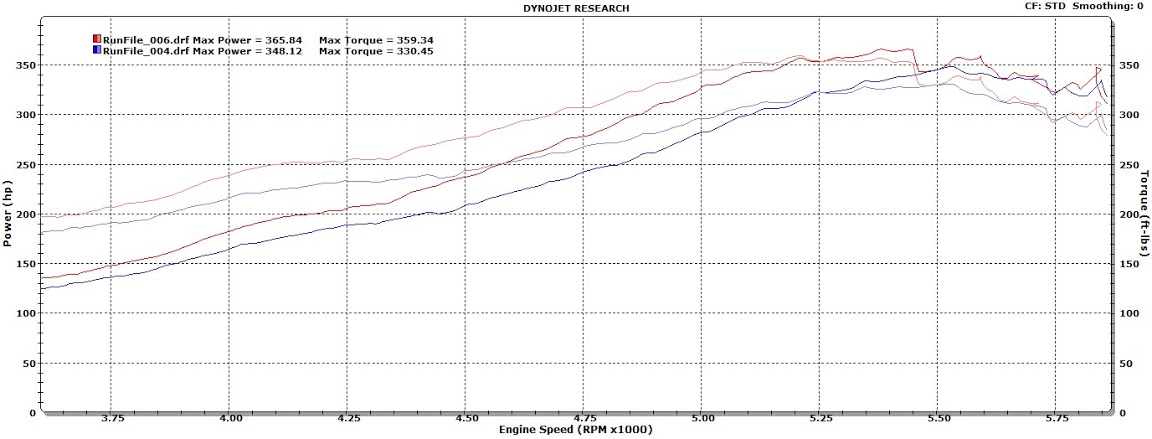
As you can probably notice, most of the build was on a budget, I did not have the freedom to shop for different turbos. However, I did come to a conclusion. VQ’s do not like T3 turbines in my opinion, VQ’s flow a lot of exhaust and require a T4. The T04b T4 turbo I had at 16psi on the VQ30 outperformed the VQ35 with a T3 Holset housing. Let me show you what led me to conclude this, observe this dyno chart below.
Holset 18cm Turbine Turbo at 14psi and 18psi.
Do not let the dyno numbers mislead you, this is about mid to low 400’s, they show as 300’s because the dyno was done with the torque converter unlocked (this is why I do not dyno very often, they do not add any value other than a safer tuning environment in my opinion). Notice that around 5500 RPM both dyno runs end up at the same power and torque output roughly. One was at 14psi and the other was at 18psi yet they both choke at 5500 RPM. I did a lot of research and asking around and concluded that the T3 housing was the cause. So my advice to you is, start with a T4 turbine and forget about being able to spool quicker with one, once you get the urge to gain more power you’ll regret having used a T3.
Here’s the video of the Dyno. I never recorded a video with the Bullseye housing but it was about 1,000 RPM sooner in spool up with it.
What would I do different from the beginning?
Nothing, my experience led me to learn all aspects of the turbo system and near the end of the rear mount turbo journey I feel I had perfected it. I have no doubt that had I kept the rear mount and used the proper size turbo, it would have performed as well as my front mount does; you can read about the front mount build. https://www.my4dsc.com/streetzlegend-front-mount-turbo-build-part-1/
Rear Mount vs. Front Mount
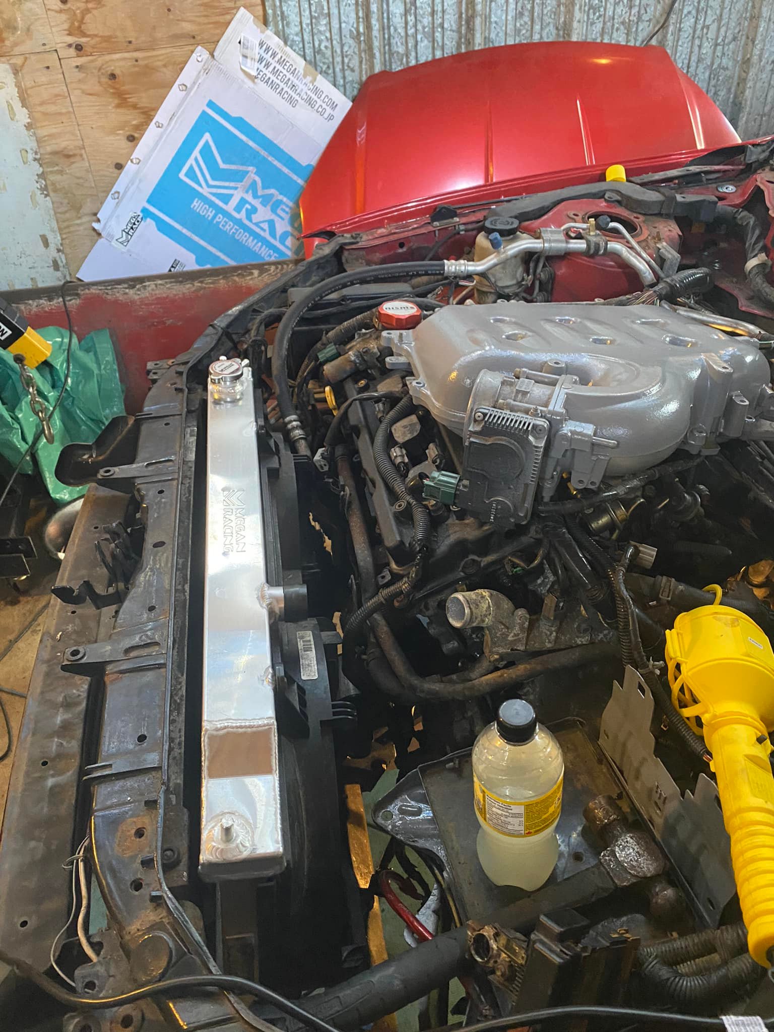
After years of using the rear mount I eventually changed to a front mount turbo. I have been asked many times why did I make this change if the rear mount turbo worked well. My first reason was because I wanted to learn how to weld so I decided to fabricate my own front mount system. The 2nd reason was weight reductions, getting more serious with racing meant weight needed to be addressed on an already heavy automatic GLE Maxima. The rear mount turbo specific parts were 80lb’s in total in comparison to the front mount. Although there were benefits in going with a front mount turbo it was never a thought nor a plan todo so. I received a welder as a gift, the maxima was no longer a daily so I jumped into putting together a front mount.
When I changed to the front mount using an HX40Pro Holset turbo the spool was similar. At the time I had a .70ar T3 Turbine housing which meant the turbo spooled up very fast both in the rear and the front. I have come to the conclusion that the difference between having the turbo in the front vs. the back does not affect the spool up as much as one would think.
Would I do another front mount? Absolutely yes, I still want to see what a rear mount turbo setup can do with a proper size turbo and I know some of you are working on it or are planning too, so I am excited in sharing this information with you.
I believe my best was 12.8 at 117MPH in the 1/4 with Holset turbo at around 20psi
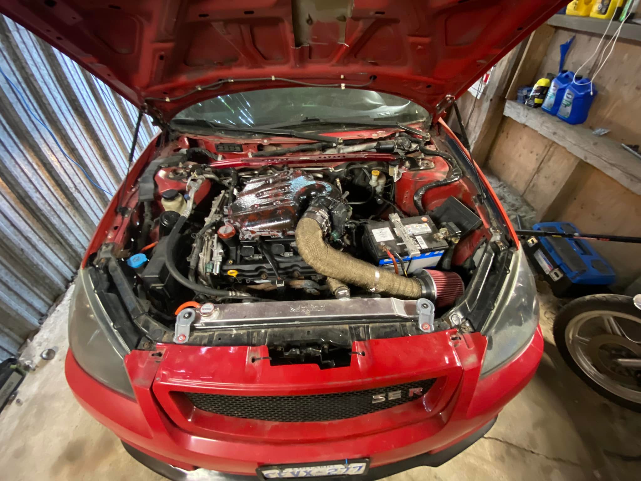
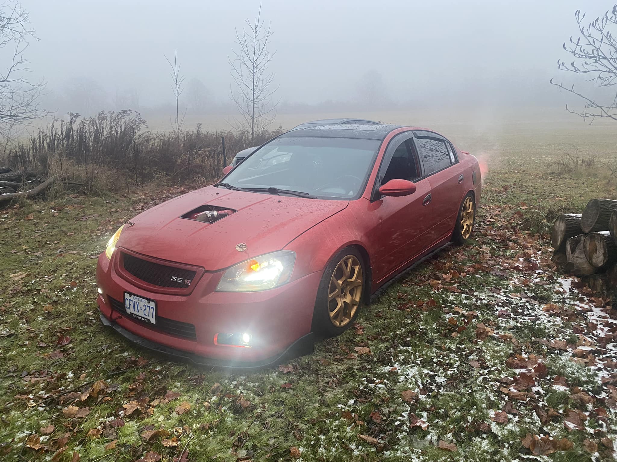
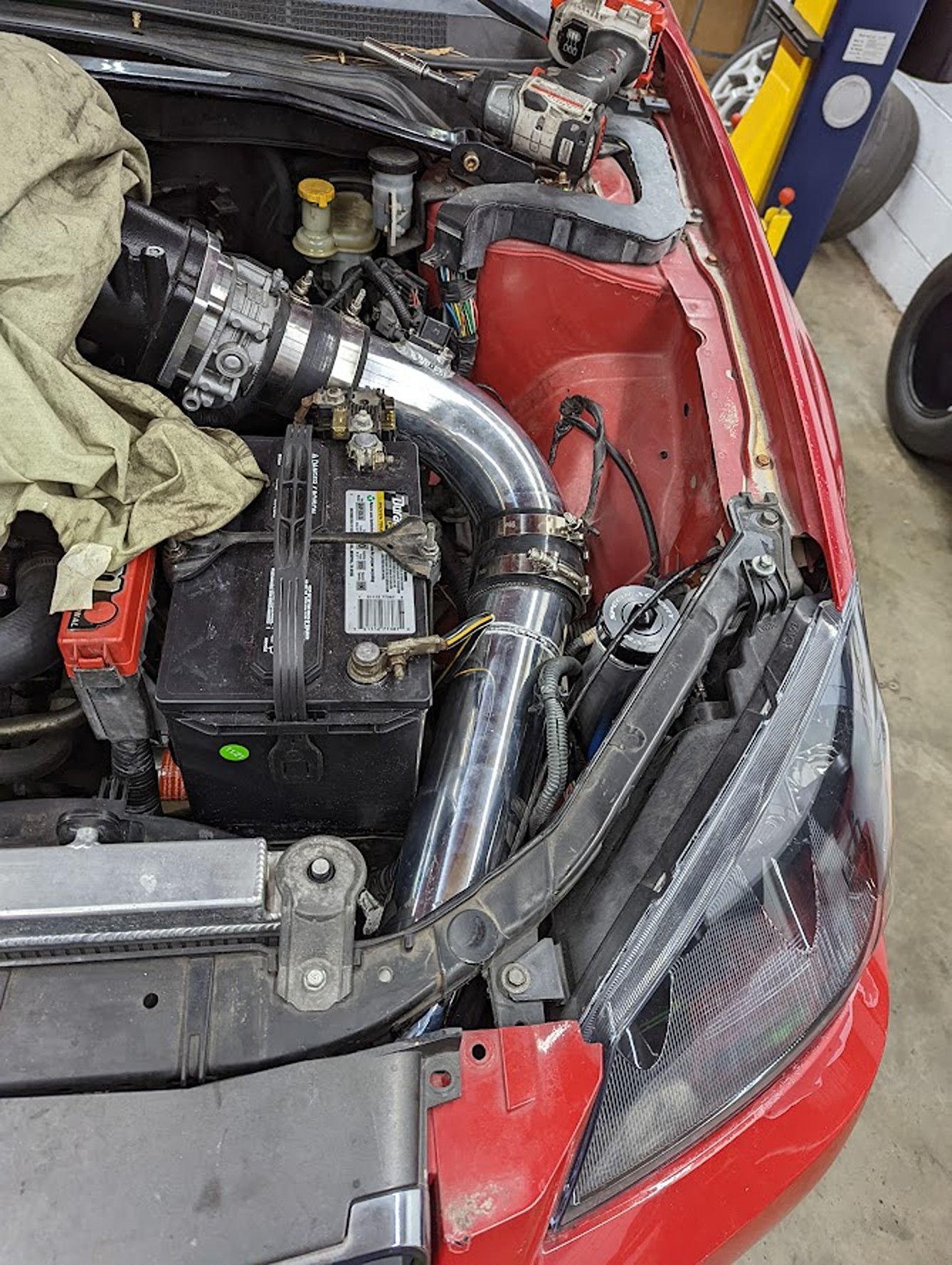
For the Altima SE-R, installing a Holley EFI lid does not require relocating the battery. There may be concern about the terminal post interfering with the intake path, but with the battery in its stock location, the highram intake, fuel cell fill neck, and supporting components can still be integrated successfully.
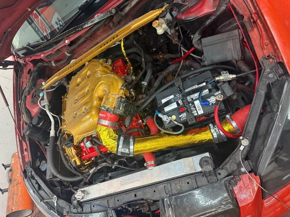
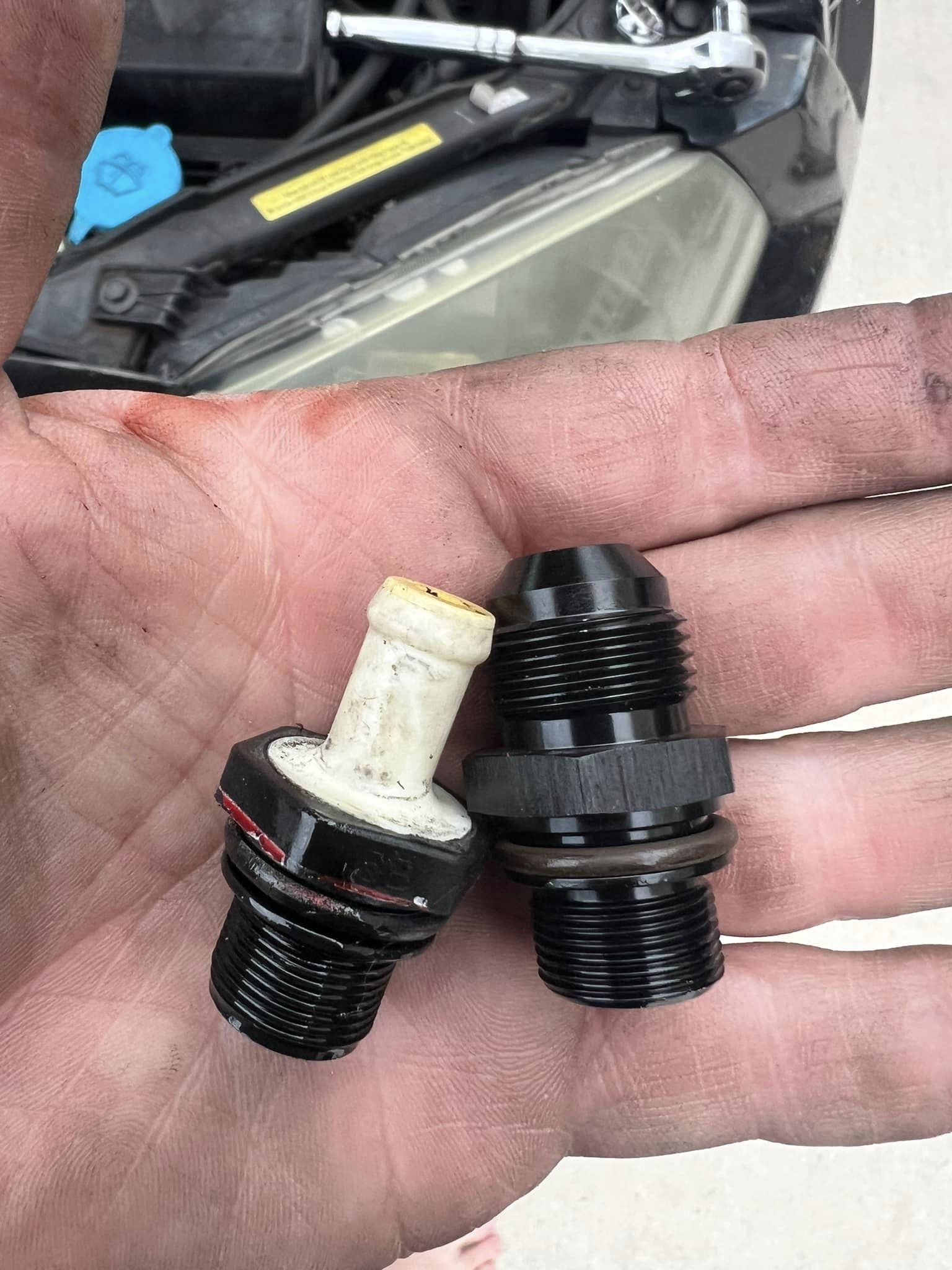
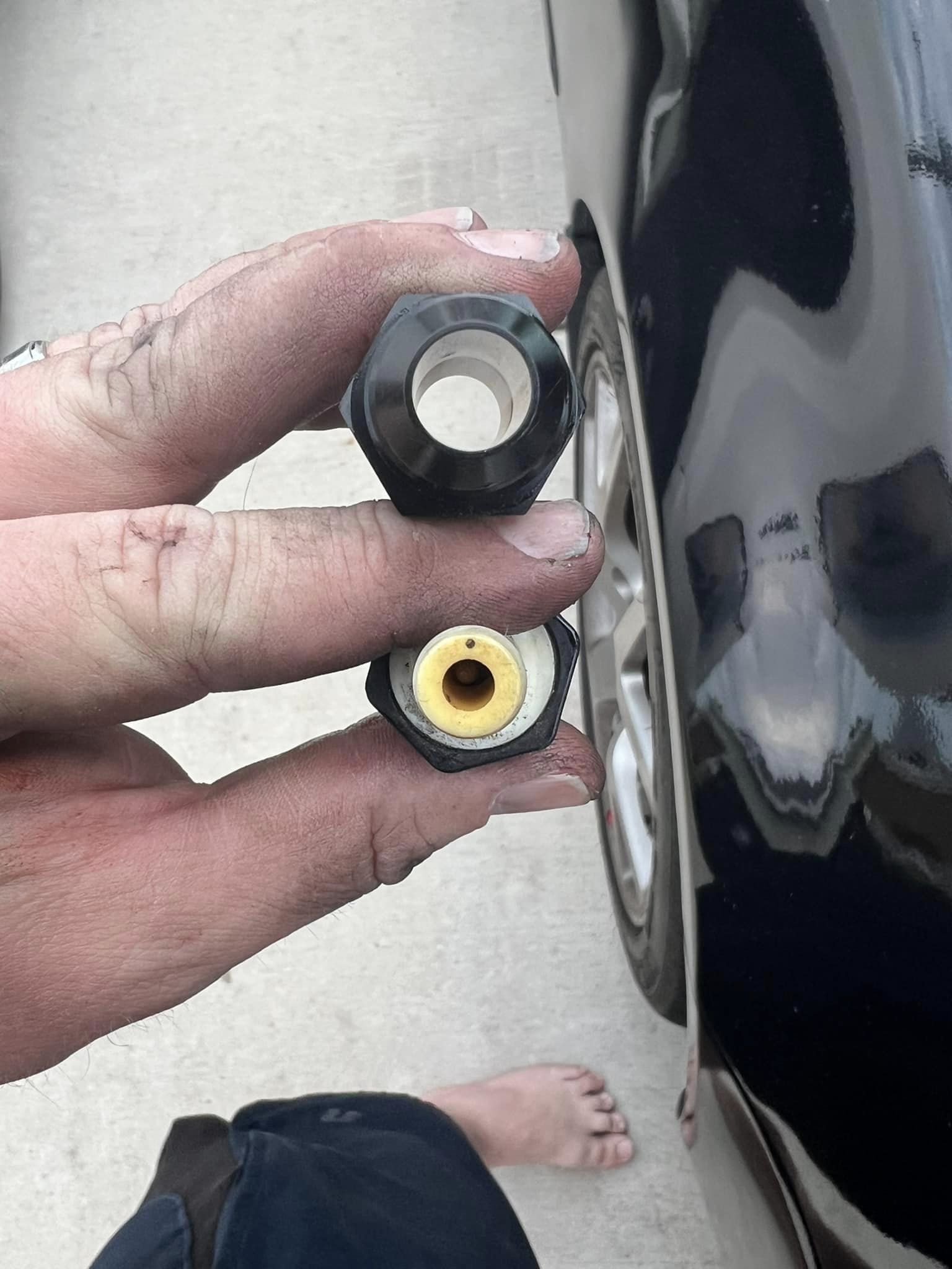
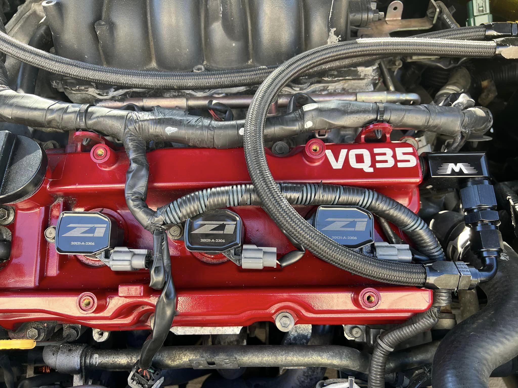
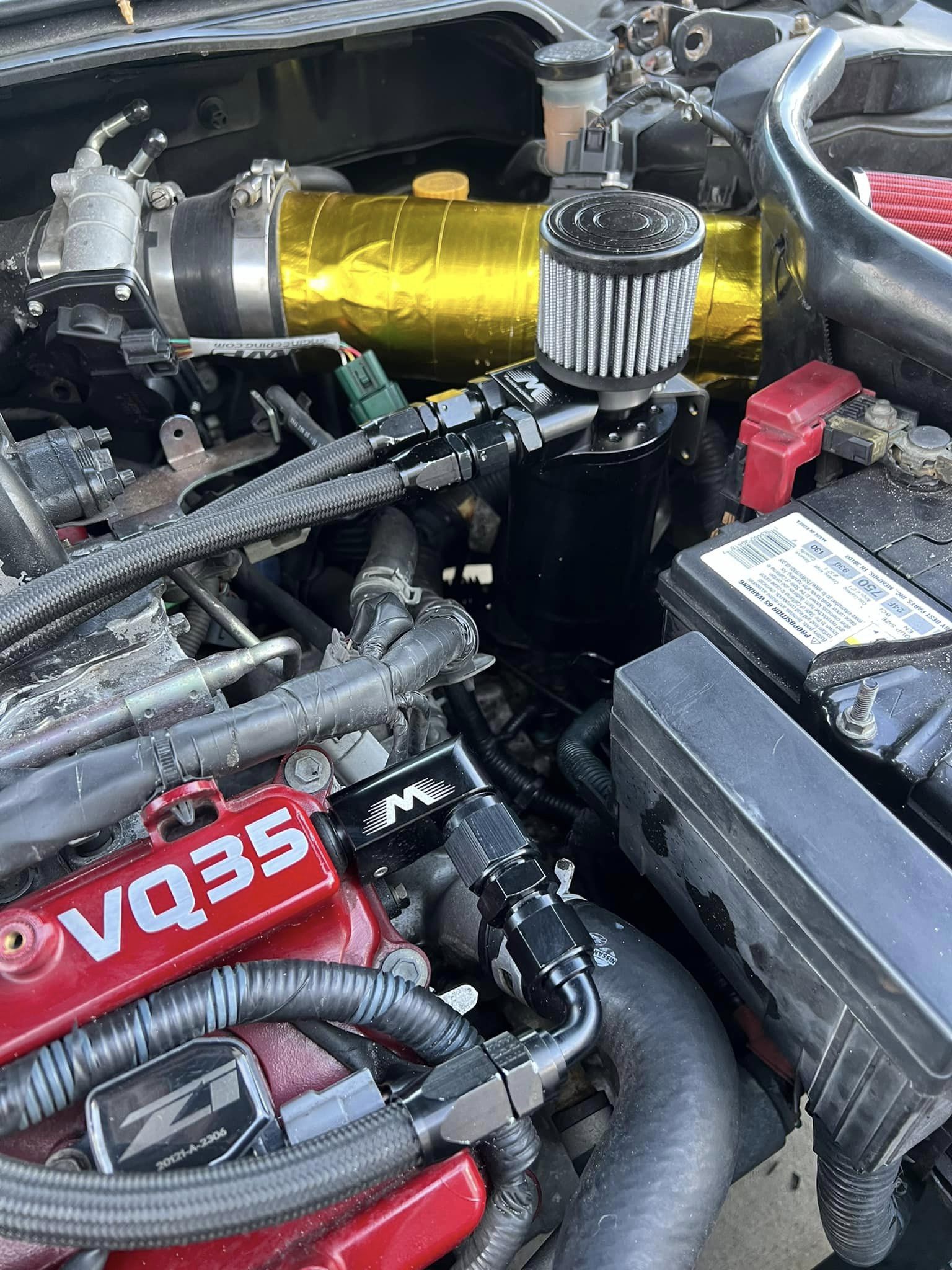
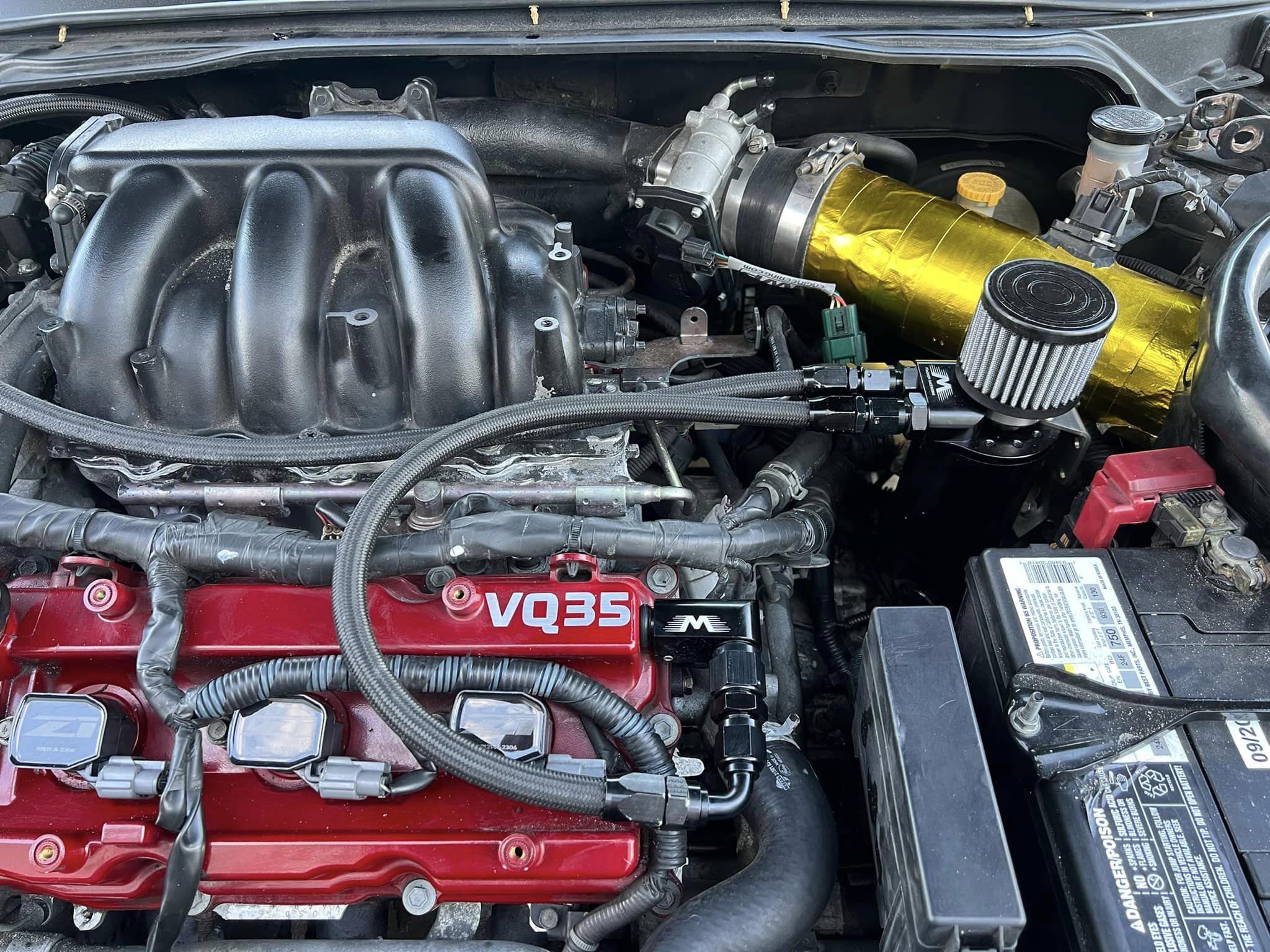
Catch can upgrade! I know this will be controversial, but I also installed Z1 high-output coils. Over the past week, I got quite a few things on the car fixed. New motor mounts, engine oil, and transmission fluid change, new AF sensors, and motor mounts. I had a cylinder 2 misfire, so I went ahead and changed the plugs, and it turned out to be a coil issue, so I opted for the Z1 upgraded coils to replace all the stock ones. This also finally gave me a reason to upgrade my old catch can system to a proper Motion Raceworks vented can with AN lines and completely delete the PCV system.


