This should assist members who have the infamous fuel gauge issues on the 00-03 5thgen Nissan Maxima. You can easily test the fuel level sensor under backseat and verify the wiring. If both test good, then you need a cluster. It took about 30 minutes to perform the test.
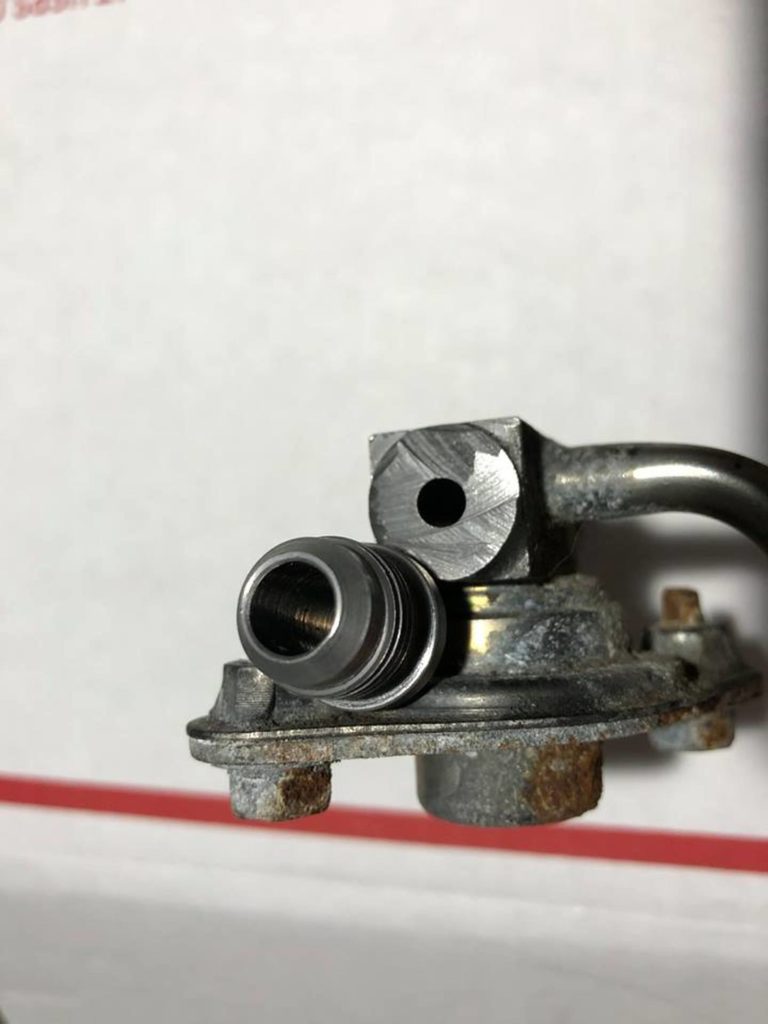
This is the size of the inlet of the stock hr fuel rails. Figured the boosted guys would like to see it. This is before the split and that is 6-AN bung next to in for reference.
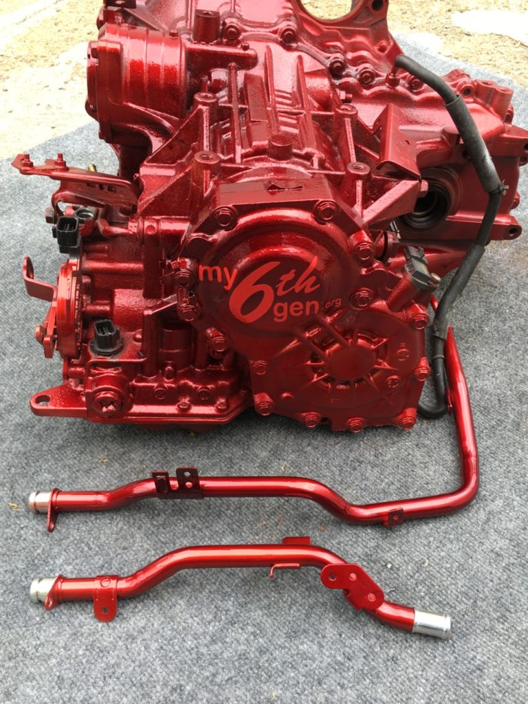
Just wanted to provide some confirmation that the 00-03 5thgen 4-Speed Auto Transmission will fit on the 2004 6thgen Maxima (4-Speed Automatic ONLY). I bought a fully built transmission from a 5thgen Maxima at a great deal. That was the only reason I went the 5thgen route. Otherwise, I would of just bought another 6thgen 4-speed auto tranmission (can be purchased for less than $350 used). The oil pan sits on the frame a bit but no big issue.
I was shopping around for quality fans for my Nissan Maxima’s (6thgen and 4thgen). The dual Mishimoto fans were not cutting it anymore. And honestly, the Mishimoto fans were really no different than the 14″ generic ones on eBay. I did some research and found a company called SPAL. A fellow member (Javon B.) vouched for these fans confirmed they work very well. All 12-volt puller models, these Extreme Performance Electric Fans offer the most flow and fan area.
My car would overheat at times when going on long cruises with the AC on. I no longer have any cooling issues at all. This fan is very powerful with 2,024 CFM and does the job with just single 16″ Fan. I’m not even using a shroud.
Make sure you use a good relay (at least 40 AMP) before connecting directly to your OEM harness. More info below:
Fan Part Number: 30102049
Fan Price: Between $100.00 -$130.00
Relay Price: It’s about $33 bucks. The part number for it is SPAL-FRH. It’s a 40-amp relay kit. Highly recommended. You can use your own relay brand as well.
Specs:
Type: High Performance – 12V Puller – Curved Blade
CFM: 2024 cfm
Height:16.22″ (412mm)
Width: 16.22″ (412mm)
Depth: 3.45″ (87.6mm)
Model: VA18-AP71/LL-59A
Made in Italy
Old 14″ Mishimoto Fans. These were 1300 CFM but certainly didn’t feel like it.
Comparison of my 16″ SPAL Fan to Mishimoto 14″ Fan
Mounted on `Mishimoto Radiator. It’s literally a perfect fit.
Dimensions
Photo of the SPAL-FRH Relay (40AMP):
If you don’t use a good relay like the one above, this will happen (Photo Courtesy of Javon Bennet)
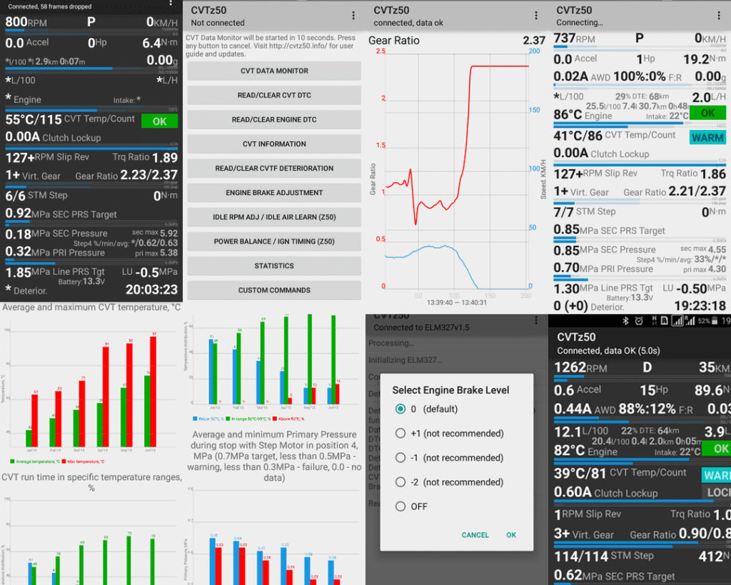
CVTz50 is an Android App that allows you to perform various diagnostics on your CVT transmission. No need to go buy special scanners, gauges and/or pay your Nissan dealer a “special diagnostic fee“. This app will tell you everything you need to know about your CVT including some additional nice features such as resetting your CVT fluid deterioration counter and adjusting your engine brake levels. Many 7thgen Maxima owners like to use this app to monitor the CVT temperature levels after installing an additional transmission oil cooler.
Special thanks to Eric Cruz for finding and validating this app for Nissan Maximas.
You will need an ELM327 interface to use the app. You can buy them on eBay for around $15 bucks. It must be an ELM327 1.5 built on original Microchip PIC18F25K80. To ensure your ELM327 interface will work, you can try the demo app here:https://play.google.com/store/apps/details?id=com.cvtz50.cvtz50demo
Applications
2007-2008 6thgen Maxima
2009-2015 7thgen Maxima
2016+ 8thgen Maxima
Also supports Nissan Murano Z50/Z51, partial support for other vehicles equipped with Jatco CVT – Nissan Teana, X-Trail, Qashqai, Juke, Wingroad; Mitsubishi Outlander, Lancer; Renault Koleos; Suzuki Kizashi; Chery and others
Main Features
Information Credit: http://cvtz50.info
Read and clear CVT Diagnostic Trouble Codes (DTC)
Read and clear engine DTC
Read and reset CVT fluid deterioration counter (CVTF deterioration date)
Adjustment of engine brake level
Adjustment of Idle RPM and ignition timing; Idle air volume learning
CVT monitoring: real-time monitoring of CVT fluid temperature, pressures, deterioration, gear ratio and many others
Monthly statistics for CVT temperature, pressure in special conditions, failed gear switching, mileage, fuel consumption, run hours and CVTF deterioration trend
Quick start
Install latest CVTz50 version from Google Play
For Bluetooth version of ELM327 interface: Connect ELM327 adapter to OBD-II diagnostic interface of the vehicle with ignition turned on and perform Bluetooth pairing of ELM327 adapter in Bluetooth settings of your Android device. If ELM327 adapter is named “OBDII” in the list of Bluetooth devices, then CVTz50 will be selecting this adapter automatically. If ELM327 adapter has different name, then this name should be set in CVTz50 options manually, otherwise CVTz50 will be asking to select adapter after each CVTz50 startup.
For WiFi version of ELM327 interface: Connect ELM327 adapter to OBD-II diagnostic interface of the vehicle with ignition turned on and connect your Android device to WiFi network of ELM327 adapter. In CVTz50 menu, select “Use WiFi ELM327” and make sure that IP-address and port are the same as specified in user’s manual of the adapter. Some Android devices require turning on the option “Connect to WiFi network even if it doesn’t provide Internet connectivity”.
Start CVTz50 and verify the connection by pressing CVT Data Monitor button. If ELM327 connection established successfully, CVTz50 will show connection progress and enter data monitoring mode.
Reading and erasing DTC
To read Diagnostic Trouble Codes stored in CVT or in engine, press button Read/Clear CVT DTC or Read/Clear Engine DTC. After successful DTC reading, CVTz50 will show number of errors stored in corresponding control module and list of the codes.
In order to erase CVT/engine DTC, press and hold corresponding button, then confirm erasing by selecting YES in confirmation dialog.
Reading and resetting CVT Fluid Deterioration counter
Press Read/Clear CVTF Deterioration button to read deterioration data.
Nissan recommends to change CVT fluid if deterioration exceeded 210000 points. Note that on majority of the vehicles the deterioration counter takes into account CVT operation only in high temperature conditions (the counter increases only when CVT temperature is above 90°C). There might be other reasons to replace CVT fluid – they shall be considered even if deterioration counter is significantly below the threshold.
After replacing CVT fluid, CVTF Deterioration data should be cleared. To perform deterioration data erasing, hold Read/Clear CVTF Deterioration button and confirm the operation by selecting YES in confirmation dialog.
Engine Brake adjustment
Press Engine Brake Adjustment button to change the level of engine braking. Current brake level will be retrieved from CVT control module and marked in the selection dialog. Select new brake level and confirm the change by pressing OK or press Cancel to exit without saving. Nissan is not recommending to select levels +1, -1 and -2.
Nissan is not recommending to select levels +1, -1 and -2.
Engine braking can be adjusted only on Nissan-based vehicles. Mitsubishi, Peugeot, Citroen, Jeep do not provide such ability in their CVT control firmware.
CVT Data Monitor mode
Press CVT Data Monitor button to start realtime monitoring of CVT parameters. Data monitoring will be also started automatically if no buttons pressed within 10 seconds after CVTz50 launched. In this mode, CVTz50 shows majority of significant realtime CVT parameters that can be seen in official diagnostic tool Consult-II:
Engine speed, RPM (corresponding Consult-II parameter: ENG SPEED)
Gear lever position or manual gear number in manual mode (in brackets when brake pedal depressed)
Vehicle speed, KM/H (corresponding Consult-II parameter: VEHICLE SPEED). Some vehicles may report here values less than real vehicle speed. For such cases, it is possible to manually select speed source: CVT speed sensor, ABS speed sensor, or speed recognized by engine control system. Speed source selection menu can be opened by long click on speed value in monitor mode.
Accel – accelerator position, values in range from 0.0 to 8.0 (corresponding Consult-II parameter: ACC PEDAL OPEN)
Engine horsepower (value calculated basing on engine speed and load), hp
Engine torque (value calculated by control module basing on engine speed and load), N·m (corresponding Consult-II parameter: VENG TRQ)
AWD %:% F:R – AWD solenoid control current and corresponding torque distribution between Front and Rear axis from 100%:0% to 50%:50% (only for Nissan-based vehicles) (corresponding Consult-II parameter: ETS SOLENOID)
Vehicle acceleration, g (corresponding Consult-II parameter: G SPEED)
Instant fuel consumption in liters per 100km and in liters per hour; fuel level sensor, distance to empty calculated by CVTz50, average fuel consumption, fuel consumed, total travel distance and travel time (to reset these values calculated by CVTz50, press and hold any of these numbers)
Engine – engine coolant temperature and color indicator of temperature range (<20°C COLD; 20-80°C WARM; 80-100°C OK; 100-120°C HOT; >120°C HOTTER) (corresponding Consult-II parameter: COOLAN TEMP/S)
Intake – intake air temperature (measured at mass airflow sensor) (corresponding Consult-II parameter: INT/A TEMP SE)
CVT Temp/Count – CVT fluid temperature in 2 different units: Celsius degrees and in “Counts” displayed by other diagnostic tools; and color indicator of temperature range (<20°C COLD; 20-50°C WARM; 50-90°C OK; 90-110°C HOT; >110°C HOTTER) (corresponding Consult-II parameter: ATF TEMP COUNT)
Clutch Lockup – torque converter lockup current; and color indicator showing up when torque converter is in locked up state (corresponding Consult-II parameter: ISOLT1)
Slip Rev – RPM slippage inside torque converter (shall be around 0 when torque converter is locked up) (corresponding Consult-II parameter: SLIP REV)
Trq Ratio – torque ratio of torque converter (corresponding Consult-II parameter: TRQ RTO)
Virt. Gear – approximate number of virtual gear which corresponds to current gear ratio
Gear Ratio – CVT gear ratio, target and actual (corresponding Consult-II parameter: DGEAR RATIO / GEAR RATIO); for transmissions with auxiliary gear (like CVT7) additional indicator ▲ shows that auxiliary gear switched from low-gear mode to high-gear mode
STM Step – Step Motor position, target and actual (corresponding Consult-II parameter: DSTM STEP / STM STEP), only for transmissions equipped with Step Motor (Jatco CVT prior to CVT7)
Approximate final torque after considering all gear ratios (based on engine RPM, load, current gear ratios, only for Nissan Murano)
SEC Pressure – actual CVT fluid pressure in secondary pulley, MPa (corresponding Consult-II parameter: SEC PRESS)
sec max – maximum CVT fluid pressure in secondary pulley observed during current CVTz50 session, MPa
PRI Pressure – actual CVT fluid pressure in primary pulley, MPa (corresponding Consult-II parameter: PRI PRESS)
pri max – maximum CVT fluid pressure in primary pulley observed during current CVTz50 session, MPa
Line PRS Tgt – target LINE pressure, MPa (corresponding Consult-II parameter: LINE PRS)
LU – target torque converter lockup pressure, MPa (corresponding Consult-II parameter: LU PRS)
Deterior. – CVT Fluid Deterioration, value in brackets shows deterioration increase during current CVTz50 session (corresponding Consult-II parameter: CVTF DETERIORATION DATE)
Battery – TCM (transmission control module) power supply voltage (corresponding Consult-II parameter: VIGN SEN) and voltage on OBD2 socket, V
Timestamp of last monitoring data update. In case if DTC appear in engine control or CVT control, then timestamp will be replaced with DTC indicator – yellow in case of engine DTC and red in case of CVT DTC.
Data updates every 5-8 seconds when CVTz50 reads data from CVT control module, engine control module and AWD control module. Update frequency can be increased to 5-8 updates per second by turning off reading of engine and AWD in CVTz50 menu.
Data charts
Data chart showing last 200 values of specific CVT parameter can be opened by pressing parameter name or value in CVT Data Monitoring mode. Red line is the selected parameter and blue line is Vehicle Speed.
Main menu (settings)
Monitor CVT – Turning on/off reading of data from CVT control module
Monitor Engine and DTC – Turning on/off reading of data from engine control module, and reading CVT and engine DTC (if this option turned off, CVT monitoring will be able to indicate only critical DTC or DTC already presented before CVTz50 launch)
Monitor AWD – Turning on/off reading of data from AWD control module
Start Data Monitor / Pause Data Monitor – this command allows to pause/resume data monitor without closing data monitor window
Data Logging To File – Turning on/off saving logs to files cvtz50.txt, cvtz50_params.txt and cvtz50_engine.txt
Consumption Correction – setting fuel consumption correction coefficient for case if real consumption significantly differs from consumption calculated by CVTz50
Alt. Consumption – Alternative method of fuel consumption calculation (for Nissan Murano). This method can be more precise comparing to default
Long Term Consumption – Turning on/off saving of travel distance and fuel consumption between CVTz50 sessions. If turned off, average fuel consumption will be cleared at every CVTz50 start
Switch Color Theme – switching between dark and light color themes (requires CVTz50 restart)
Force English Interface – forcing English interface language for those who prefer to disable localized translation
Font autoscaling – Turning on/off automatic selection of font size in Data Monitoring mode
Tune font scale – correction of font size in Monitoring mode for case if text labels overlap
Voice Notifications – voice notifications for CVT temperature levels (notifies when CVT fluid reaches temperature levels 20°C, 50°C, 90°C) and new CVT and engine DTC
Keep CVTz50 in foreground – prevent Android from closing CVTz50 running in low memory condition
Change default Bluetooth adapter – setting adapter name that will be selected by CVTz50 automatically without need of manual adapter selection from the list. Bluetooth MAC address in format “12:34:56:78:9A:BC“ allowed here (if MAC address specified, CVTz50 will not show adapter selection dialog even if there is no paired device with such MAC address).
Turn off Bluetooth on exit – turn off Bluetooth on Android device upon exiting CVTz50 in case if Bluetooth was turned on by CVTz50 on startup
Bluetooth Compat (*) – Bluetooth compatibility modes (different modes of Bluetooth security, speed). Compatibility settings should be used only in case of inability to setup Bluetooth connection or in case of Bluetooth connection instability.
Always Reconnect – more aggressive connection/reconnection mode. When enabled, CVTz50 will be continuously trying to connect to ELM327 which may lead to high battery consumption
ELM327 v2.15 Workaround – compatibility mode for “bad” ELM327 adapters
Use WiFi ELM327 – use WiFi variant of ELM327 adapter instead of Bluetooth. After selecting this option, additional dialog will be shown allowing to set adapter IP address and port.
Primary Pulley Pressure automatic test during stop
CVTz50 automatically tracks primary pulley pressure while vehicle stopped in D position after CVT fluid temperature reached 50°C and Step Motor got position 4. Under these conditions, primary pulley pressure should not drop below 0.5MPa. Once these conditions met, CVTz50 will display additional information block near Primary Pulley Pressure – Step4 %/min/avg showing percentage of Step Motor setting to 4 during continuous braking from 40km/h to 0km/h (more is better), minimum and average pressure during stop (closer to 0.7MPa is better). The block will be highlighted by yellow if minimum value drops below 0.5MPa; highlighted by red if drop below 0.3MPa.
This automatic test is applicable only to CVTs equipped with Step Motor (prior to CVT7).
Pressure test during acceleration
During intensive acceleration from 0km/h (engine speed more than 3000 rpm), primary and secondary pulley pressure shall reach at least 5MPa. This test shall be performed in CVT-only monitoring mode (monitoring of engine and AWD turned off in CVTz50 menu) to ensure enough measurement sampling rate. Maximum primary and secondary pressures will be shown in fields sec max and pri max.
Note: maximum values can be reset only by exiting CVTz50 so cvtz50 should be restarted before each attempt.
Acceleration time measurement
In CVT-only monitoring mode (monitoring of engine and AWD turned off in CVTz50 menu) if accelerator pedal fully depressed, CVTz50 automatically measures acceleration time 0-50km/h, 0-100km/h, 0-150km/h, 0-200km/h. Measurement result will be shown near indication of gear lever position. Measurement accuracy is around 0.25s if data updated 4 times per second.
Monthly Statistics
During monitoring, CVTz50 collects statistics on CVT temperature conditions, pressures, milage, fluid deterioration, engine runtime and other data. Statistics button opens new window showing graphical representation of collected statistical data which can be checked for any trends (like month-by-month pressure decrease illustrating fast CVT wear). Backup copy of statistical data is stored in Google account (if Android device is linked with Google account and applications data backup was not turned off during Android device setup) and will be restored in case of CVTz50 re-installation or during migration to new Android device using same Google account (if during migration to new device user allow “restore applications and their data from previous device”).
CVT Information
CVT Information button opens new window showing following information retrieved from TCM (transmission control module):
Calibration Identifier – set of digits which is usually unique for each CVT assembly. Calibration data is stored in valve body (on CVT prior to CVT7) and copied to TCM during pairing of specific valve body with specific TCM
Last 5 previous CVT DTC and time of their recording by TCM in “warm engine run hours” (not all DTCs stored here by TCM)
CVT-A and CVT-B parameters which are showing number of occurrences of error conditions
Run hours – engine run hours counted by TCM. Rounded up to 10-minute intervals during each engine start. Counter resets when erasing TCM EEPROM (e.g. during TCM firmware update or TCM replacement). Counter stops increasing after reaching 10922 hours.
Run hours (warm engine) –run hours of warmed up engine. Counter stops increasing after previous counter reached 10922 hours.
Idle Rpm adjustment and Ignition Timing adjustment
Idle Rpm Adjustment can be started by short pressing of button Idle Rpm Adj / Idle Air Learn (Nissan).
Ignition Timing adjustment can be started by long pressing of button Power Balance / Ign Timing (Nissan).
After starting an adjustment, CVTz50 reads current adjustment levels from engine control module and mark it in adjustment selection window. Press OK to save newly selected adjustment value to engine control module or press Cancel to quit without saving.
Adjustments can be performed only on warmed up engine. Idle Air Volume Learning might be required before performing these adjustments.
Idle Air Volume Learning
Long pressing of Idle Rpm Adj / Idle Air Learn (Nissan) button initiates the learning procedure. Learning should be performed on warmed up engine, all electronic load need to be switched off. Idle Rpm Adjustment and Ignition Timing adjustment need to be set to 0 before starting this procedure.
Power Balance Test
Power Balance dialog allows to temporary disable fuel injection in specific cylinder. Dialog title shows current engine RPM and minimum RPM observed after last switching of cylinders. This test allows to compare performance among cylinders.
Custom Commands
CVTz50 allows to send any custom commands or command series to ELM327 or to any vehicle control unit.
CVTz50 optionally can connect to CVT control module or to engine control module before executing entered custom command.
Logging CVT parameters to file
Log containing main data exchange between CVTz50 and ELM327 adapter is stored in file cvtz50.txt which can be found on memory card of Android device.
CVT realtime parameters recorded during monitoring are stored in file cvtz50_params.txt which can be opened by Microsoft Excel for detailed offline analysis.
In engine-only monitoring mode, engine realtime parameters are stored in logfile cvtz50_engine.txt.
Frequently Asked Questions
Q: Does CVTz50 work with UBS variant of ELM32, can it run on iOS or Windows Mobile?
A: No and there are no plans to add their support in the futureQ: What does specific DTC mean? What is the meaning of specific CVT parameter?
A: Most reliable information can be found in Electronic Service manual for specific vehicle which also describe potential causes for major DTCs and corresponding diagnostic and recovery procedures.Q: Why Primary Pressure is always 0 and Step4 test does not show this pressure while other parameters displayed correctly?
A: Some vehicles do not have Primary Pressure sensor so this parameter is always displayed as 0
Where to buy ELM327 Interface
Fastest and most reliable way of getting proper ELM327v1.5 is buying it at local store. Check it immediately with CVTz50 or CVTz50 DEMO and get moneyback if it unable to connect to transmission. Just one disadvantage – price of the interface will be higher comparing to online stores.
It is also possible to buy a good ELM327 interface via Ebay or Aliexpress, search using keywords ELM327 PIC18F25K80 (PIC18F25K80 is name of the chip inside majority of “good” adapters). The problem is that some sellers are still shipping “fake” interfaces regardless of mentioning the name of good chip in item’s description, especially sellers offering lowest price. So before placing an order, it is necessary to check with the seller whether their product really has proper version 1.5 and build on appropriate hardware. Sample query to a seller: Is your ELM327 1.5 built on original Microchip PIC18F25K80? What’s the frequency of crystal oscillator there, 4mhz or 16mhz? Does it support commands ATAL and ATPPS?
Difference between good and bad ELM327 interface
Casing of good and bad interfaces is the same (many variants of cases exist however all of them can have fake components inside) so it is needed to look into internals. Many online stores provide pictures of disassembled devices allowing to recognize obvious fakes (though pictures in online shops are not always real).”Good”, “real version 1.5” ELM327 interfaces are built on chip PIC18F25K80 produced by Microchip. As a rule, such interfaces are properly listed as “version 1.5” in online stores. Android application ELM327 Identifier after analysis of such device show that the interface supports all commands of ELM327 protocol till version 1.4.”Bad” (or fake) interfaces are built on cheap microcontrollers like STM32F042, BK3231Q, 25K80 QBD327 and unknown chips hidden under black drop of special varnish. Such interfaces are usually recognized as “Chineese version 2.1”, however many unfair sellers are selling these as v1.5. Moreover, when connected to diagnostic software, poor interfaces can report version 1.5 so they are “fake v1.5” (actually they can show any number there). If “bad” interface is not trying to trick the user, than ELM327 Identifier will show that many v1.4 commands are not supported. However if fake ELM327 programmed to cheat diagnostic software, ELM327 Identifier can show same result as for good interface or even better.Special attention to new kind of fake adapters introduced in 2017 – built on chip QBD327 relabeled as PIC18F25K80. Such relabeled chips have following specialities:
Microchip logotype (M) on fake chip is blurred (while original chip has clear and sharp logo)
Third line of the label on fake chip has string 14309MP or 1643URE; original chip has another strings with encoded production date
Fake chip uses crystal oscillator with frequency 16.000MHz (usually located near the chip); original PIC18F25K80 requires crystal oscillator 4.000MHz
Fake ELM327 does not support command ATPPS; good ELM327 recognizes command ATPPS and responds to it with list of hex numbers (ATPPS can be sent to the adapter using “Custom commands” in CVTz50 DEMO).
Difference in pictures
Good ELM327 interface: microchip PIC18F25K80 and crystal oscillator 4MHz.
Might be built on one PCB (like on the picture), or on two or three PCBs soldered together
Bad ELM327 interface: fake microchip PIC18F25K80 with label 14309MP and crystal oscillator 16MHz
Bad ELM327 interface: microchip STM32
Sometimes such interfaces can work with limitations in mode “ELM327 v2.15 compatibility”
Bad ELM327 interface: unknown chip hidden under drop of varnish
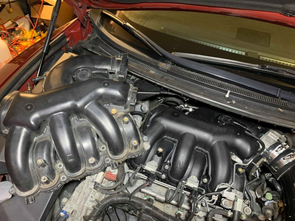
The 2016+ 8thgen Intake Manifold directly fits the 2009-2015 7thgen Maxima. It will also fit other gens (4thgen, 5thgen, 6thgen) that have done the Gen2 VQ35DE (aka HR) engine swap. These can also be used to swap your 2007+ Altima Manifold to a Maxima one (direct fit as well).
You can find and buy these manifolds on eBay for around $150 or less.
Please Note:As of now, there hasn’t been any testing to prove additional gains in comparison to the 2009-2015 7thgen Maxima manifold. We will provide an update as we learn more.
Here is the P.Side all tucked with the fuse box still in the engine bay.
Just for info on how to remove the Anti Skid Control Actuator clip. Pull the handle out like a drawer and it will release the clip.
After tucking the wires on the P.Side there wasn’t enough length for the driver side to stay as is. This is where all the fun began!
Battery, Battery Tray, Fuse Boxes Removed
Here are all the wire that run out from the internal fuse box. The fire retardant caulk was a b to get off..
The wires that go to the engine fuse boxes will now run inside the white plastic boxes along the side of the car to the trunk where the fuse boxes will now reside.
New home for the battery and engine fuse boxes. Deciding where to put the battery. Will most likely keep it in the spare tire bay, build a riser to hide everything, and lay the oem carpet back over the top.
Here are the only wires that will run out to the driver side from the internal fuse box. D.Side Head light, Fog Light, Airbag, and Horn.
Current state now is where I started on the engine harness. Laid the heads and a few other parts in to just help give me an idea of the room I will have to work with and where the wires will need to go. I will pull the wires through the fire wall that need to go to the trunk. Whatever has to stay in the engine bay will stay untaped and out of the way for now until the engine is put back together. This way I can tuck, hide, and run everything in it’s new permanent spot.
Pulled apart the fire retardant caulk on the wire that go through the fire wall to the ECU.
The wiper motor wires now run through the frame instead of over the strut. That screw is where the ground wire goes to now.
The wires pop out through the frame here and meet up with the other wires that will go back to the trunk.
Here is an idea of how everything will be sealed off. Using the stock gasket. Just gotta tape it up.
Here is everything taped up. Not taping the gasket yet because I may be running the master cylinder and left front abs through here.
This is behind the headlight. You can see in the upper right of the pic there are welded nuts. They are where the grounds used to go on this side. I had a clip and screw laying around and it fit perfectly here to mount the grounds a little farther back. All grounds were cut to size and soldered together.
This what the old battery location looks like now.
I also did some work on the passenger side but nothing worthy of taking pics yet. Should be finishing that side this week.
I need some help on this. This clip has always just free floated since I bought the car. It’s right by the driver fog lamp. Anyone know what this and where does it clip to. I want to put it where it belongs lol.
Talked to Altima02Dub and the EGR wires can be removed but the injector wires need to stay. Anyway, here are some small update photos.
Wires fit perfectly under the plastic protector. Removed the rear seats and now I have easy access to the trunk to start soldering some wires back together.
Started the weekend with removing the EGR, Secondary O2’s, and Vacuum clips/wires.
Did a little work under the dash
Random shot of the interior but you can see under the dash is cleaned up a little
Need to get some larger gauge wire to extend these last few on the driver side
Engine bay with a mess of cut and labeled wires
Engine bay cleaned up with most of the clips back on and somewhat organized.
Here is one of the many things I did today. Stupid ABS wires are in clear eye site. No way to really hide them perfectly. Here is the driver side. I ran it up and around the back of the strut tower along with the brake fluid wires Best I could do without completely deleting the ABS (which I seriously thought of doing).
Starting wiring up the IPDM
Here is a shot from the other day. Completely finished the brake actuator clip. Instead of the wires running along the frame they will make a u-turn up through the fire wall.
Last night I extended some more wires to the IPDM. Also, took apart the fuse box by the battery and started wiring that up too.
Battery Box and Wires came in this weekend!!
Had some time before work this morning and put a few clips in place. When I was clipping some trans wires in I noticed a hole in the trans I can run some wires through. I ran two of the trans clips and the starter wire through here.
Close up shot.
From a small distance. You can barely see them
Ran a few more wires today in the small block of free time I had before work. One cool part was the ALT power wire.
I bent the small tabs the other way
Now the wire runs down instead of up. I was pretty stoked how I worked out.
Spent all day on the engine bay. Here a few shots of the semi final product.
Shot of the engine bay with almost all parts installed
Close up of the coil pack wires. Notice how I hide the solenoid wire
Injectors zip tied in a u-turn to hide them a little better.
Side shot of the engine where all the wires will meet. Wish I could hide it better but this car has so many clips. It’s the best I can do right now.
All the wires in the engine bay meet up here behind the rear valve cover and go into the firewall. I basically eliminated the three engine wire harnesses and made one harness. Although, for now I will still use the oem rear injector and rear coil pack harness as is. It’s under the intake manifold anyway and you won’t see them.
Finished. A few brackets to cut off and shave down and a little cleanup to do but the wires are done.
For about 8 months now, I have been having problems with my VSS (Vehicle Speed Sensor). My speedometer and odometer would intermittently stop working while driving. It would trigger my CEL (Check Engine Light). The CEL code was 0104, VSS and sometimes 0504, Automatic Transmission Control Unit Signal to ECU.
About 6 months ago, I bought a new (used) VSS from fanaticrock, the “4th gen parts guy” for a good price. Well, after procrastinating for 6 months, I finally installed it the other night. It took no more than 90 minutes so I am upset at myself for waiting so long. It’s really a 10-15 minute job. Most of my time spent was 1.) Finding the location of the stinkin’ thing and 2.) Actually pulling it out of the transmission!
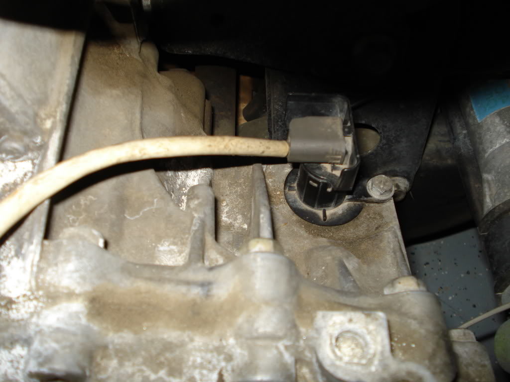
The Chilton’s and FSM (Factory Service Manual) show no pictures. The Haynes shows a picture too zoomed in to know exactly where it is. And, the instructions in the Haynes say to raise the vehicle. So I spent way too much time under the car looking for it. Turns out, it’s on top of the transmission (located near the fire wall). The extent of the Chilton’s is “unplug, unscrew, pull out”. No pictures, no explanation of its location.
Instructions at autozone.com, basically the same as the Chiltons. The FSM was worthless. But, I did finally find the VSS location. Sorry, I do not have any pictures, but I could take some if anyone really needs them.
Once I found it, aside from having to reach in deep into a fairly cramped space, it was a breeze to unplug the harness and unscrew the one retaining bolt (you can access it from standing on the driver side of the engine).
Where I spent another frickin’ half hour was trying to actually pull it out of the transmission. It is tight! And the sharp shape of the top of the VSS hurts your hands. I had to double up on gloves. I eventually got it. The new one was also tough to put in the tight hole but I eventually got it in.
So far, problem solved! No bad odo/speedo nor CEL. I have driven the car a dozen times and for ~200 miles. I think the problem would have already occurred if it was going to.
I just thought I’d share in case anyone else is having similar symptoms/needs to change their VSS. I tried to use key words to aid future searchers. I hope this helps.
– Josh
VSS out of the transmission: The wiring harness. You may not need to change this, I did just because Fanaticrock sent me one with my VSS: Zoomed out pic. General area of where you’ll stand and reach in when changing the VSS (excuse my filthy engine bay, this is my ’96 which is my beater car): This is where the VSS is located – on top of the transmission:
Ok, first I need to mention that I will try to add more pictures, so there may be edits in the near future. Also, can a mod please PLEASE please make this a sticky! I spent a lot of time doing this to try to help others, so I hope that it will!
I decided to do a write up for those who are considering doing a rebuild on the Maxima 5-speed transmission. First I must say, this is not a job for a beginner in any way shape or form. I am not a professional mechanic but I have been working on cars since I was able to hold a wrench. I must give credit to Maxima.org and to Motorvate, for this wouldn’t ever have been possible for me to do without their help. Many thanks!
I will try to break it down in steps as to what to do when and how to get it done. If there is a will there is a way. My rebuild did not go off with out a hitch, there were certainly some issues to deal with along the way. I will walk you through how I did mine and you can compare it to the one on Motorvate.com. My soul intention in doing this rebuild was to remove and replace all of the bearings and seals. I bought my kit from GtTransmissions and it was a fair price. I did not replace the synchronizers nor did I remove any of the gears from the shafts. I did make several stops at the hardware and tool store, so I will try to compile a list of the tools I needed to do this job. I also replaced the clutch, which was the easiest part of this job. I used hand tools, I don’t own a compressor or impacts. I did however buy an electric 1/2″ drive impact along the way. (240lb of torque is hard to argue with )
Tool List:
Tire Chalks
Floor Jack
Jack Stands
Torque Wrench (I use a 1/2″ drive)
Ratchet and metric socket set (10mm, 12mm, 14mm, 17mm, 19mm, and a 36mm)
Extension set (you’ll need several) – Swivle head (very very handy, but you can get by without one)
Open end / Box end wrenches – metric (12mm, 14mm, 17mm) – I suggest ratchet wrenches (well worth the money!)
Breaker bar (long pipe to fit over ratchet or wrench)
Gloves – leather are good (just get a good pair, don’t go cheap, you’ll be able to get a better feel with better gloves)
FSM (Field Service Manual)
Parts (bearings / seals) (clutch)
Thread lock
Gasket sealer – get the red stuff, just don’t get it on you
Rubber Mallet and regular hammer
Degreaser (Engine foam works well)
Dremal Tool (with cutting blades – I use the reinforced ones and they last a while)
Punch (3/16″)
Pry bar (various sizes are good to have)
Sand paper (I used 240 gritt)
Preparation:
Ok, first step in all of this is to READ ALL of these instructions, then re-read them again. Gather your tools and then lift the hood and remove the battery (including the tray), intake (up to the TB), starter, slave cylinder. The spedo sensor (10mm bolt, above the shift linkage) can be a beotch to get to – leave it in, disconnect the wire for now. After all of the wires and sensors up top are unhooked, it’s time to jack the car up and place it on the stands.
Removing the transmission from the car:
Make certain the car is in N, with the parking brake on. Place a chalk behind each rear tire and get out the floor jack. In the center of the front of the car you’ll see a small bump on the crossmember. Depending on your jack, you may place a peice of wood between the jack and this point, to get the car high enough to work on. Jack up the car as high as you can, the more room you have, the better. I placed my stands on the controll arms (long thick bracket with 3 bolts in it – not the sub frame rails!). I wasn’t able to get the car as high as I would have liked, but it worked. The first step I did was to drain the gear oil from the trans. (you can check it using a maganet and if you have any chipped inner / outter races, there may be metal in the oil. If you plan to reuse (not reccomended) the oil, make sure you use a clean tub to catch it in.) To drain the oil, you can pull out the shift selector switch (40mm on the bottom drivers side) but if you do this, be careful not to break it – the plastic gets brittle as it ages) or you can use the drain bolt under the shift support rod. Once this is done, take the wheels off. (note, you’ll have to loosen the lugs prior to jacking the car up) With the wheels off, take out the center cotter key and get the 36mm socket. This is why I bought the electric impact to be quite honest. And … it was worth it I used the handle of my jack and slid it between the lugs. Be careful not to use something that will damage the lugs or bend and damage you. Take off the center retaining nut (36mm) and washer. Next, take a 17mm box end wrench and a deep well 19mm socket and unbolt the strut knuckle bolts (2 each side). This will allow you to swing the rotor assembely out of the way. You may have to rotate the strut about 90º so the rotor will move just that little bit more. With that done, slip the CV shaft out of the hub. (Be careful not to put too much strain on the brake line while doing this, it does fit and if it’s not working, something is wrong.) Now, holding onto the shaft (not the boots!) push the shaft in and yank it out. Should come out pretty easy, just be careful not to hurt the threads on the end, or the splines on either end. The passangers side is a bit different, there are 3 – 14mm bolts that hold a bracket which in turn holds the longer CV shaft. The bracket can be easily reached from inside the wheel well (you’ll need extensions). Remove the bracket and remove the CV shaft.
Next step is to get the transmission out of the car. Pull the trans mount (drivers side) out, you’ll need a 14mm to do this. (hint: It’s easiest to pull the center retaining bolt first, so the socket can slip past it and onto the rear bolts) You’ll have to remove the clutch line from the mount as well as the retaining clip on the side. Once you get that done, you’ll need to go under the car and unbolt the shift rod and shift support linkage. (this is where the 14mm gear wrench come is real handy) Remove the CPS (front – 10mm) from the trans housing. Also, while you’re down there, unbolt the bottom trans bolts. (no – it’s not gonna fall on your head just yet) Next thing to do is to remove the remaining bolts from the trans. This is where it comes in very handy to have a bit of muscle around to help you out. The transmission weights in at around 109 lbs and it’s not the weight that makes it difficult to handle, it’s the odd shape and sharp corners. With all the bolts removed, you may still have to pry the trans loose from the bell housing. BE CAREFUL not to drop the trans while doing this. (I got under the car and wiggled the trans while a mate of mine pryed a bit from the top. It gets hung on the pins coming off the bell housing, into the clutch housing.) Lower the trans (use a jack if you can – good luck!) I just lowered it to my chest and then slid if off and out through the drivers side wheel well. You can’t just drop it straight down either, because of the clutch and IPS (input shaft) splines. Once the trans is out, set the clutch housing face on some wood – so as to not scratch it or nick it.
Transmission break down:
Now that the trans is out and you have taken a breather, it’s time to open this puppy up and see just how bad those bearings have gotten. The case bolts are all the same with the exception of a couple (mid diff and opposite side – really long one) and they are 14mm. Remove the TOB and shift release fork from the clutch housing. If you didn’t remove the spedo sensor, now is a good time. If you left the shift selector switch in place, leave it for now, we’ll get to that in a moment. Remove all the case bolts. There are two hex bolts (14mm) on the top part of the trans – with the differential sitting to the right. These are the 1-2 and 3-4 detent bolts / springs / check balls. Inside behind the bolt is a spring and a ball, do not loose them. Remove the bolts and the springs / check balls. Before the lid will come off, you need to remove the R bolt (12mm – just under the 1/2 – 3/4 detents). Then the lid should come off easily. This is what a 5spd Nissan Maxima trans looks like. Now the fun begins! Be carefull not to loose the shims (thin metal rings atop the IPS) remove the shims and the plastic peice covering the IPS bearing. Set the lid and the shims aside.
The FSM is about as clear as mud on some of this stuff … so I’ll try my best to tell you how I did mine. (which is different I know – but it works) The proper way to do this is to remove the R shaft pin. Mine did NOT want to come out and play nice, so it stayed in. This is NOT a screw. (the R pin is on the left) :Pic 1 Below: From inside the trans, slide a strong enough wire between the gear stacks (IPS) (left) and MS (main shaft) (right) to the back of the pin. Push the pin out and twist at the same time from the outside (there is a flat head on it that looks like a screw). The pin can get stuck (like in my case) and not want to come out. I decided to go about it another way in this case, since mine was being so stubborn. Remove the two springs on the R assembely. Note which way the inner sping is going. Select 4th gear and remove the R gear. Remove the two 12mm bolts and lift the R assmebely up. Remove the “C” clip from the 5/R fork (top and bottom come off). Also, remove the top and bottom “C” clip from the 3/4 fork. (If the R shaft pin comes out, you will not need to drive out the 5/R shift rod retaining pin) Next, take the 3/16″ punch and find the pin on the 5/R shift rod – punch it through. This can be tricky, just think of it like a jig saw puzzle, you’ll be fine. Remove the 5/R detent on the clutch housing, this is the detent for the 5/R rod. Remove the spring and ball behind the hex head. Now you should be able to remove the 5/R rod and fork. You’ll have to slip it past the R assembley and at the same time, don’t loose the spring or larger check ball (found in the bottom of the R assmebely – see pic – it’s the larger hole at the bottom). With the shift rod / fork out, you can remove the 3/4 shift rod as well. There are more check balls and interlock plungers here … BE CAREFUL not to loose any of them. Use a maganet to remove them all after you take out one shift rod, remove the check ball and interlock plunger. You should be left with the 1/2 shift rod / fork and the IPS and MS (and if you didn’t get the R assmebely out, it should be there too) This is IMPORTANT: Lift the IPS and MS and the 1/2 rod all at the same time and straight out. The differential will just be sitting there, it will then lift out too. Teardown is well under way now. You can seperate the IPS and MS and put them on something that will not damage the gear teeth. Set the differential aside as well. Now is a good time to remove the shift selector switch if it’s still in. Remove the bolt (10mm) and then use a rubber mallet to pop the switch out. Last but not lease you need to remove the gear selector rod and the R gate. (there is a check ball here …. don’t loose it.) Drive out the retaining pin from the fluid drain hole for the selector rod. Remove the two 14mm bolts on the R gate and lift it out. Note how it looks as you take it out.
Pic 1
Bearing removal – the unconventional way!:
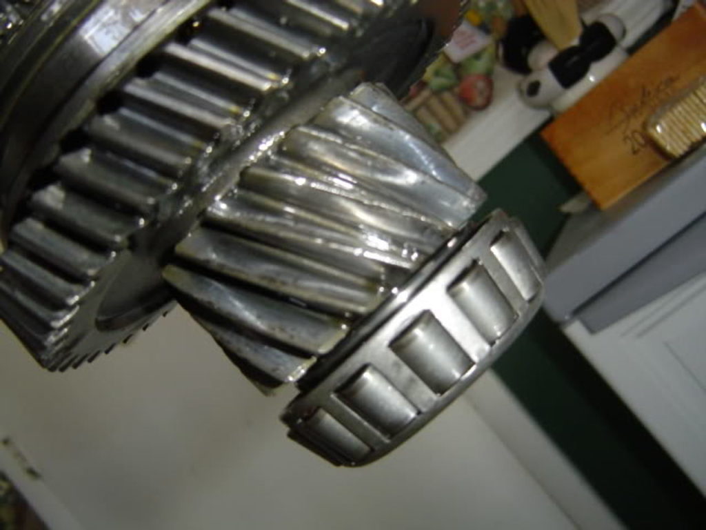
Hope you have a good Dremel tool and some cutting blades. This part was the most scary for me, and I would have much preffered to have the bearings pulled / pressed on / off … but I couldn’t afford to pay a shop to do it, nor could I afford the “propper” tools. I say “propper” cause … as long as the job gets done, and done right, it shouldn’t matter what tools you use. I wrapped the shafts with a towel to protect the gears as much as possible. Leaving only the bearing showing, I cut off the outter shell of the bearing. :PIC 0 Below: This makes the bearing almost, but not quite, fall apart – leaving the inner race (part that slides onto the IPS). Remove the balls and outter shell. I had to cut all the way through the outter shell and the ball ring to remove them. Wear some eye protection, last thing you need is a hot piece of steel in your eye. (I also suggest long sleaves and a good thick pair of gloves – it’s gonna get warm) With the outter shell off, cut into the inner race. Try not to go too deep, and if you can, cut a cross or an X into it. (something for you to be able to place a screwdriver into the slot and get a bite on it) Put the chissle or screwdriver into the newly cut slot – smack the crap outta it. The object is to get the bearing loose without having to cut all the way throught it. (heating it up with a tourch may help as well) If you can get a good enough bite, the smacking will spin the bearing on the shaft – thus loosening it and it will come right off. This is how I did all of my bearings. The differential can be a bit difficult becasue of the spedo ring, don’t cut through that or melt it either – or you will be replacing it or living without a spedo. :Pic 2 Below: The roller type beaings (MS and diff) :PIC 2a Below: (this is the bottom of the MS – old bearing still in place) will come off by cutting the top and bottom of the outter shell, then the pins will drop right out leaving the inner race. (I cut mine in 1/2 on either side – worked very well) DON’T place any new bearings on untill you’re done cutting. You don’t want to have metal shavings in your brand new bearings. I took a can of Dust Off and sprayed the shafts after I was done cutting to help remove any micro pieces of metal. With the bearings all removed, now we can put the new ones on and start putting this all back together.
Pic 0
Pic 2
Pic 2B
Bearing replacement:
Here’s a picture of the bearing / seal kit I got. :PIC 2b Below:Take your trusty 36mm socket and have it handy! Get an extension (6″ or so – this is so when you need the end of the socket that fits the ratchet, you can place the extension into the socket and hit it instead of trying to hit all the edges at the same time). Set the bearing on the shaft (or diff) and place the socket on top of the new bearing. (depends on which bearing it is, you’ll use either end of the 36mm – which ever side lines up to the inner race) :PIC 2c Below: Use a real hammer, not the rubber one, and give a good forcefull and firm smack to the socket. It should start the bearing on straight so you won’t have it slanted to one side or the other. Do this untill the socket “dings” off the bearing. This is how you know the bearing is seated fully and poperly. (you should use the punch to be certain that it’s on all the way. hit at 12, 6, 3, 9 untill the punch bounces off the race) It will make a different sound as well. There should be no mistaking if the bearing is on all the way or not. Do this for all the bearings. I placed a peice of wood under the new bearings while doing the oppisite side – just to be safe. The hard part of this is not placing the new bearings, but removing the old ones without damaging the shafts or diff. If your bearing kit has this ring on it, take it off – it’s not needed. (IPS bearing, clutch side) :PIC 3 Below:
Pic 2B
Pic 2C
Pic 3
Transmission case:
First … make sure you have every thing out of the case (top and bottom). There should be 9 check balls (note that one is larger – it’s from the R assembly, 3 springs (1 long, 2 shorter) and 2 interlock plungers. If you don’t see those, don’t continue. You will want this thing clean enough to eat out
of. Spray the degreaser in the csase and let it soak. After your coffee break, spray off the degreaser and let it dry. You may have to do this a couple of times (I did) to make sure it’s all nice and clean. Don’t forget to hit the clutch housing on the under side too. With everything clean and dry, it’s time to start putting it all back in. To remove the outter race (part of the beaing still in the case) you’ll need to remove the plugs from the lid. Use a long screwdriver or punch to remove them. With the pulgs out, it’s easy to get a punch onto the bottom of the outter race. Smack it out and replace it with the new one. The MS outter race (in the clutch housing) :Pic 4 Below: was not replaced, it didn’t look too bad and to get it out would require a low profile bearing puller – not worth it if it looks ok. Otherwise, good luck – you’ll need it.
Seal removal / replacement:
There are a total of 3 seals (two diff and one shift selector rod) to be replaced. The seals are actually a metal ring with rubber molded around them. This is a good thing for us … as we can use a punch to remove them very easily. The diff seals are placed in from the outside of the case. I’ll repeat that casue I know how I am and I didn’t catch that the first time I read it either so … The differential seals come out and go into the case from the OUTSIDE. The selector rod seal you can get a hold of with some pliers and just tug it out. (helps if you walk it out, 3,6,9,12 and pull … pull, pull) The new one will go right in with the help of the rubber mallet. The differential seals will slide in from the outside. I reccomend leaving the passangers side out for now (DO NOT FORGET TO PUT THIS IN PRIOR TO INSTALL – or you will be very very sorry) The reason I leave the diff seal out is so that while you are putting the trans back together, it isn’t destroyed, chipped, or broken on the piece of wood. Just don’t forget to put that seal in.
Reshimming the diff bearings:
I need to add this to my write up, thought I did at one pointe, but maybe not. When you place new bearings on the diff, it will change the “pre-load” on the bearings when the case is all put together. The factory places shims behind the outter race (cup) in the case cover. Only that side, not on the clutch side. These shims place a certain amount of pressure on the bearing to keep in in place and not allow it to float around. You don’t want the shims to be too tight, or too lose either way. There are a couple of ways to meassure the thickness you’ll need. I’ll go into that in a moment, right now, I am just trying to explain what the shims are, how they work, and where they are located.
Ways to meassure needed shim thickness –
The first way I will describe is considered the “Solder crush meathod”. This is the meathod I used personally and it worked just fine for me. First off, you need to make certain the bearings are all the way seated on the diff. The punch should bounce off the race and that will let you know they are all the way down. Place the diff in the case and then take two peices of solder (thick stuff, but not so thick it will not crush properly), cut them the length of the bearing. The ends should be even with the outter race. Place the solder in an X formation (this means that one peice will need to be just a little longer and bent in the middle so it sits right). Place the case cover on and place the bolts back in at several places around the case. I did all of them around the diff and several in other places (every other or so). The idea here is to crush the solder to the thickness needed to hold the bearing in place. If you end up with lettering on the solder end, you can’t use that reading, discard and repeat. You should end up with 4 flattened solder ends. You need to take those ends and measure them. The readings will be 0.xx numbers (like 0.68). They will likely not be the same. It’s ok, you’re going to add them all up and then divide by 4 to get the average. Look up that number in the FSM and get the part number. You’ll need to special order the shim(s) from Nissan.
The other way to measure is to use a micrometer and do the same set up as above. The bearings all the way seated, case cover on and bolted down. Use a pin type micormeter (depth gauge) and push the pin head against the race of the bearing. You want to meassure to the case cover outter race. It’s hard to describe and the space will be so close, it’ll be hard to see clearly. Again, the numbers will read very small. (like above) Go to the FSM, get the part number and order.
Keep in mind there are VLSD and NON VLSD transaxles and they are not really seperated in the FSM. The chart / table will tell you, but don’t do what I did and order shims for a VLSD when you don’t have one. lol Make sure when you talk to Nissan that your part number matches theirs.
Transmission assembly:
Ok, now that the old bearings, seals, and outter races are replaced and the case is clean, it’s time to put it back together. You’ll need to get the torque specs from the FSM or your Haynes / Chiltons book. To start, replace the selector rod and then replace the R gate assembely (don’t forget the small check ball) (this is under the diff, above the selector rod) and tighten it down. Next place the diff in place. Make sure it is centered, it should spin freely. Now, it’s time to place the MS and IPS (including the 1/2 shift rod / fork) back down into the trans. The way I found easiest to place it all in is to hold it up and align everything first, then slip it in. It will slide all the way in but the IPS lower bearing will not sit all the way in, it only goes in two-thirds the way. (it’ll stick out a bit) Make sure you look at the FSM for the next part here! Place a check ball and then the larger interlock plunger against the 1/2 shift rod. Then place a check ball on the oppisite side. (ball, larger plunger, ball) Then place in the 3/4 shift rod / fork. Place the other plunger (smaller one) against the rod. Then place two (2) check balls in the channel. (rod, plunger, check ball, check ball) then the 5/R shift rod (this will be tricky if you didn’t remove the R assembly- but it will fit) Next to the 5/R rod, place the last check ball and the longer spring, put the detent bolt in and snug it down. Now take the larger check ball and lift the R assembly up, place the ball in the lower hole (use Vasaline to hold it). Select 4th gear and slip in the R gear. Snug the R assembly down and replace the springs and the locking pin. Place the shims on top of the IPS and the oil sealer (plastic piece) (use Vasaline to hold the shims if needed). Don’t forget to place the selector switch (goes on the shift selector head – small white and copper piece) and the R shaft locking pin in place. Set the lid on and slide it down. (you shouldn’t need to force it – it should line up and go on easily, it may take a tap or two to get it all the way down. Make sure it fits then lift it up and place sealer around the lip – don’t use too much, you don’t want it to seap down into the case. If you removed the selector switch, replace it after you snug all the bolts down. Shift through the gears and make sure it is hitting each gate like it should. If it doesn’t, something is likely wrong and needs to be fixed prior to doing the install. (Get the torque settings from the FSM)! TaDa …. you have just rebuilt your 5spd transmission. MAKE SURE YOU PLACED THE DIFF SEAL ON THE TRANS PRIOR TO INSTALLATION !!!!
Clutch:
So easy a monkey could do it. (if you’re not doing the clutch, just move on to the installation)
It’s a good idea, while the trany is out, to do your clutch. Here is how to do it. Your new clutch should have come with an alignment tool, you’ll need it.
First thing to do is to remvoe the old clutch. There are 9 bolts that hold the pressure plate to the flywheel. The friction disk sits inside between the pressure plate and flywheel. Once the old clutch is off, take some 240 gritt or so sandpaper and just go over the flywheel a time or two. Next, get the clutch and the alignment tool. Place the tool through the PP and FD, align the bolts and torque them down to specs. Done.
Transmission installation:
There are a couple of different ways to get the trans back on the bell housing. I found it easiest to just lift it in to place and have a mate start a bolt or two at the top and I got a couple started from the under side. This can be sorrta tricky because the trans has to line up level with the clutch so the splines will slide all the way in. I got the trans up and then my mate pushed it snug from atop. Made it much easier. The other way to raise the trans is to place it on a floor jack and slide it in through the drivers side wheel well. Just make sure it doesn’t fall on you or the ground. It really is best to have help with this part. Once you have a couple bolts started, it’ll hang on it’s own. Take a breather and then place the rest of the bolts in the housing. (note … some go into the bell housing (engine block) and some go into the clutch housing (tranny) from the other side. It helps to keep the bolts seperated so you know which came from top, which came from the bottom. After you get the trans up and bolted on, reattach the shift support rod and gear selector (note the shorter bolt goes towards the rear and a 14mm gear wrench will save you time and frusturation here more than you know). Replace the CPS at the front. Next step is to install the trans mount (drivers side). Bolt the mount to the trans first and then place the center bolt in and snug it up. Remount the slave cylinder and the starter (the starter can’t go on prior to torquing the housing bolts). I like to finish up where I am working before moving on to something else, so I did my intake and battery after the slave and starter. Take a quick moment and sit in the car and run through the gears. It should shift and it may be stiff, but it should be ok once the gear oil is in. Now it’s time to replace the axles. It shouldn’t matter which side you do first, but I found it easiest to do the more difficult one (passangers side) first. Be very careful not to gouge the seal with the end of the axle. It is tricky with the bracket in place, but it will slide in. (sit on the left side of the rotor assmebly and guide it in with your left hand – support the outter end of the axle on your right arm) Make sure it’s all the way in. I had mine not seat all the way even though I had the mounting bracket aligned and all 3 bolts started. (you may have to try and reach in and (holding the axle – not the CV joint) give it a push, it should go in. You can also look up above the shift support rod and see if the axle is in all the way.) Place it back in the hub and then start the strut knucle bolts. You may have to reach behind the outter CV boot and help slide it all the way into the hub. Tighten up the 36mm (don’t forget the washer) and place in the cotter pin. Tighten the strut knuckle. Go to the drivers side and this one is a lot easier. Place the axle in the trans (you should feel and / or hear it “click”) Slide this one back into the hub and repeat the process you just did on the passangers side. Replace the tires, lower the car, and tighten the lugs. VERY MPORTANT :::: Don’t forget to fill the trans with gear oil (4.5 quarts of GL-4 75w – 90) To fill the trans, you will need an oil pump. Test drive and make sure it all feels ok.
















 The wiring harness. You may not need to change this, I did just because Fanaticrock sent me one with my VSS:
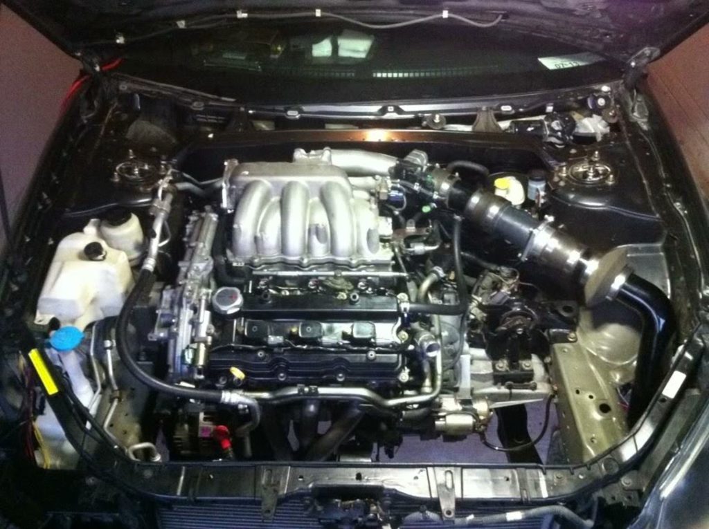
 Zoomed out pic. General area of where you’ll stand and reach in when changing the VSS (excuse my filthy engine bay, this is my ’96 which is my beater car):
 This is where the VSS is located – on top of the transmission: