Part Number: 450-8920
The pulley is from a 1993-1997 Infiniti J30 TIMING IDLER




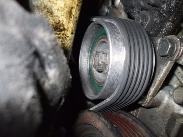

Community Member Credit: i30ds
I took my time and saved a bunch of cash for a host goodies. Best ball park guess (includes shipping) $3500…
This included a lot of new stuff:
Just about the only thing that were used are the shift and control rods, the clutch and brake pedals, and a couple of the hard clutch lines. With the rods and pedals, I took them to my grinder and removed all the rust and them repainted them with rust proof stuff.

First, I removed the seat (only 4 bolts and a couple of connectors), the steering wheel trim, lower dash panel and the metal bracket behind it, the trim around the gauge cluster and pulled the cluster out (but left it connected), and the 4 nuts that support the steering wheel up. I used a jsck stand to support the wheel so that way it would not be just hanging there bottoming out and possibly causing some damge.

Now with all this stuff out of the way I now had enough room to remove the auto brake pedal/bracket. In order to do this I also had to remove the left steering wheel support bracket which is held in place by 3 nuts, and 2 of them require access through the cluster area which is why I removed it. With that out of the way, the brake pedal was only 4 nuts and a couple of connectors (but the 4 nuts can be a b!tch to get at).

I now had enough room to drill through the fire wall for the clutch master cylinder. I bought a right angle adapter for $35 from home depot (drilling in this tight of an area would have been IMPOSSIBLE with out it and I dont know how the other guys could have done it).

I also bought a STEP bit for $10 from home depot (I dont know why the hal write up called it a ‘tree’ bit). If you are thinking about just using a 3/8 bit (the size of the two holes for the studs that come from the clutch pedal bracket through the fire wall), forget it!! I tried to do this but the bit is too long, even with the right angle adapter. You need the step bit which gets progressively bigger as you go down the bit.

For the hole for the mater cylinder I used a 1-1/2 hole saw bit (once again, I dont know why the hal called a cylinder bit). This is the exact size for the master cylinder.

With all this, I drilled my holes (sorry I for got to take pics), and mounted the cluch pedal and the master cylinder. I know the master looks off center, but the holes lined up perfectly from the inside and the pedal bracket mounted up to the other factory bolt holes (that were previously unused) perfectly as well. This makes me think that the insulation in the engine bay is what is off (for some reason or another). It is moot point regardless.


Finally, I put the brake pedal in a long with the left steering wheel support bracket (I dont know why the hal threw his away, with out it your steering wheel is only half way supported), and put everything back together. The clutch pedal is NOT attached to the master cylinder in these pics (I have a new one on order), and this is why the clutch pedal sticks out more than it should.

Fidanza flywheel, 5th gen clutch, clutch master cylinder, clutch slave cylinder, ss clutch line from the GD, Raxles axles, AE clutch/brake/gas pedals, B&M short throw shifter, AE shift knob, shift support rod mount, manual tranny mount, plate bolt with transaxle hole cover, shift console trim piece with boot, a lot of misc. bolts and nuts, and of course a brand new LSD 5spd tranny.
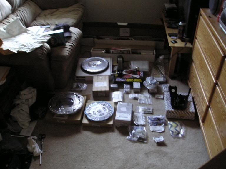

Here is all the auto junk I ripped outta there. This includes all the little bullsh!t cables and brackets. I even removed the key interlock cable completely instead of just taping it into position like Hal did in his write up. 
This was the only connector I ended up having to cut. It is the connector that went to the auto shift lever. I couldnt get it undone because the prvious owner had spilt soda down in there and it solidified the connector into one sh!t mess. I had to cut it. 
While I was in there, I decided to replace the rear main… As you can see I had the slightest seep.


I rvt’d the hell outta the thing so it should not be a problem for a really long time…
Here is the signal plate on the auto drive plate. As you can see, the signal plate is not even shaped right to work with a manual flywheel. Not to mention it is riveted on. This delayed my project as I had to buy a used flywheel, so I could get the signal plate off of it for my Fidanza. 
Here is the Fidanza with the signal plate on it. 
Gotta love how there is already a factory hole… Only if Nissan would have done this for the firewall.

Here are the shift rods… Sorry this was the best pic I could get, because there is not a lot of room under the car. 
Here is the car with everything ripped out. 
Here are pics of the pedal install. I did this back in May while I collected more parts. I just continued to drive around auto with manual pedals. 


Here is the tranny adaptor for my 3 ton jack. This thing is great. It gives plenty of room to rest the tranny on and it has slots so you can strap it down. It also can pivot and turn so you can mount the tranny with ease… Best $40 Ive spent.

Here is the Fidanza flywheel mounted.

Here is the 5th gen clutch.

Here are the Raxles axles. These things are top notch… The best looking axles I have ever seen. There even filled with amsoil grease.


Here is the B&M STS topped of with an AE shift knob. The look is proper… The way the shifter should have come from the fatory, instead of the ugly @ss flagpole.


Here is a shot of the ss clutch line.

WOW… Look at all the extra room now that the auto is gone.

Ahh… Finally back together again! 
Community Member Credit: Ben Garner
The ECU monitors the transmission-mounted speed sensor to determine vehicle speed. When the vehicle speed limit is reached, the ECU cuts the fuel flow to the engine to slow the car. Ok, in no way do I condone breaking any laws. I figured out how to get rid of the speed limiter on the 4thgen with automatic transmission. This also works on 5thgen Maxima with automatic transmission.
The signal path for the vehicle speed sensor is as follows:
If the signal is interrupted at the actual connection to the ECU, speedometer, odometer, and cruise control functions are preserved. The ECU does not receive a vehicle speed signal, therefore it will not limit the vehicle speed. This modification is easy. But beware, it does include modification of the factory ECU wiring harness…not for the inexperienced.
Tools and Supplies Needed:

Disconnect the negative battery terminal
 Remove ECU cover from passenger side footwell.
 Loosen bolt in the center of the main ECU connector using your 12 mm Socket / Socket Wrench and Extension.

Unplug the main ECU connector. Remove snap-on plastic cover from ECU connector.

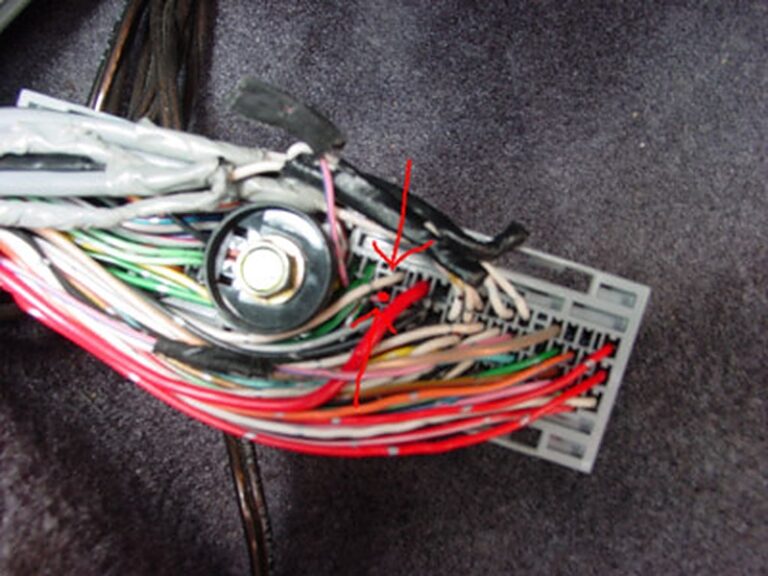
Locate PINK wire with BLUE stripe. (This wire is located on the right half of the connector when plugged in ECU PIN 29)

Cut PINK/BLUE Wire (It is recommended that you wire this up to a separate switch so you can turn it on/off when needed. Ensure that you do not cut the Fuel Temp Wire as it is also PINK/BLUE)
If you check the codes, you will get P0104 (Vehicle speed sensor fault) and P0504 (A/T control unit fault). To prevent the CEL you can use a switch to switch on/off for the quick burst for going over 120+ MPH. So far there have been no drivability problems associated with this mod.

Reassemble ECU connection and Reconnect negative battery terminal.

Verify the speed limiter/governor is removed by going past your previously limited speed.

Disclaimer: This mod is entirely up to you so do this at your own risk. This modification will cause the “check engine” light to illuminate.
Community Member Credit: CS_AR
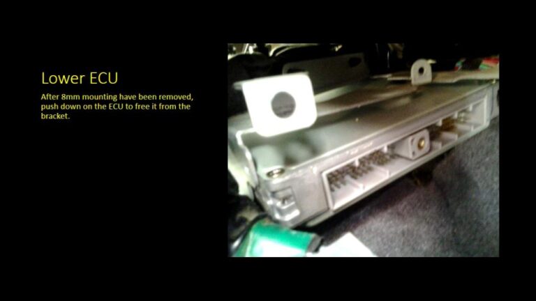
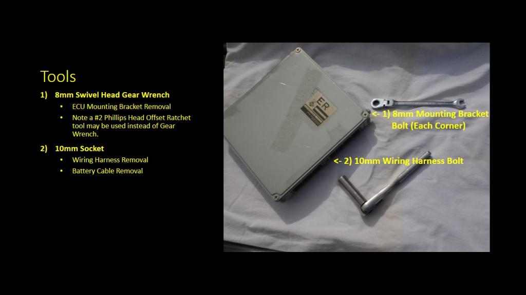
Here’s a slide show I pulled together this morning after I removed the ECU from my 99 Maxima. I read some ECU removal instructions and was able to remove the ECU in about 20 minutes or less.
While I purchased a new Offset Ratchet Screwdriver Tool with a #2 Phillips, once I started the job, I quickly realized my existing 8mm Swivel Head Gear Wrench would stay mounted on the ECU bracket bolts and make the removal go faster.
Step 1 – Disconnect Battery

Step 2 – Remove ECU Covers

Step 3 – Remove ECU Wiring Harness

Step 4 – Remove Left Side ECU Mounting Bracket Bolts

Step 5 – Remove Right Side ECU Mounting Bracket Bolts

Step 6 – Lower ECU Away From Mounting Bracket

Step 7 – Remove ECU


Reference photo of the VQ35DE Engine Firing Order for the Infiniti. Very helpful when it comes to diagnosing P030x CEL Codes.
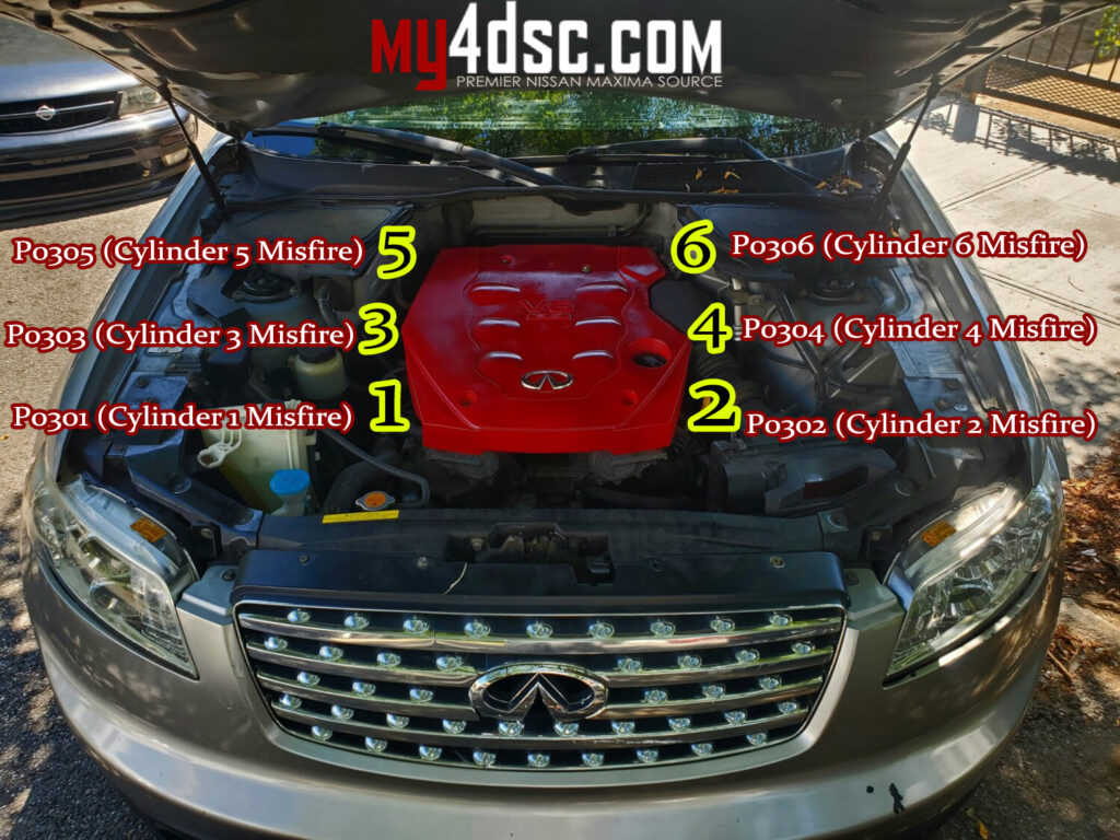

If you have a CEL for random misfire, below the common codes.

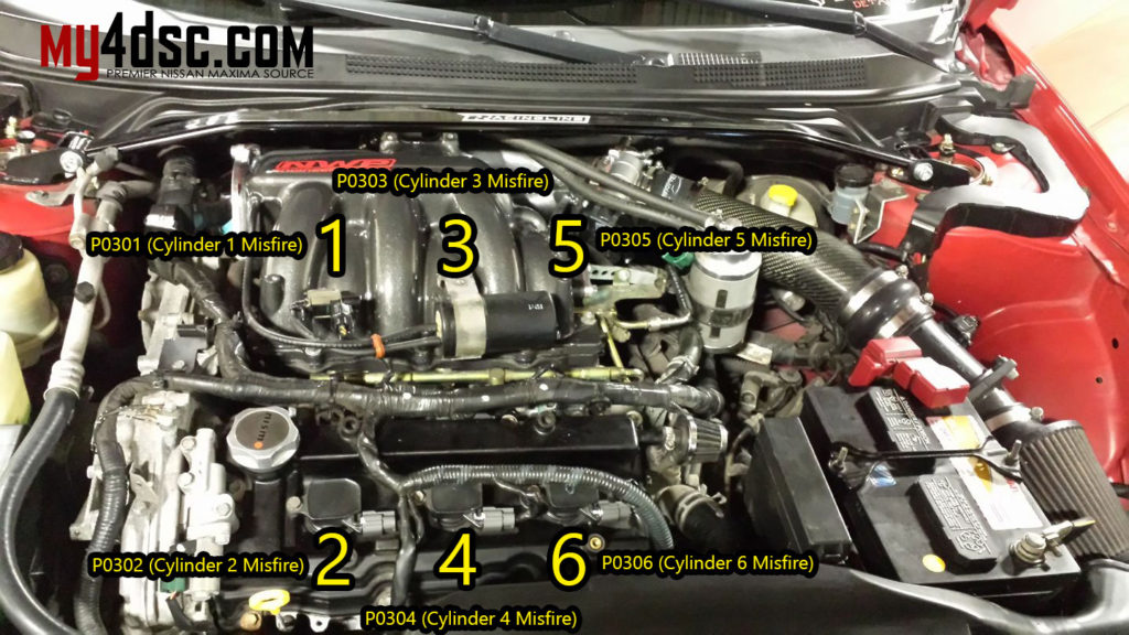
Reference photo of the VQ35DE Engine Firing Order for the Nissan Maxima. Very helpful when it comes to diagnosing P030x CEL Codes.
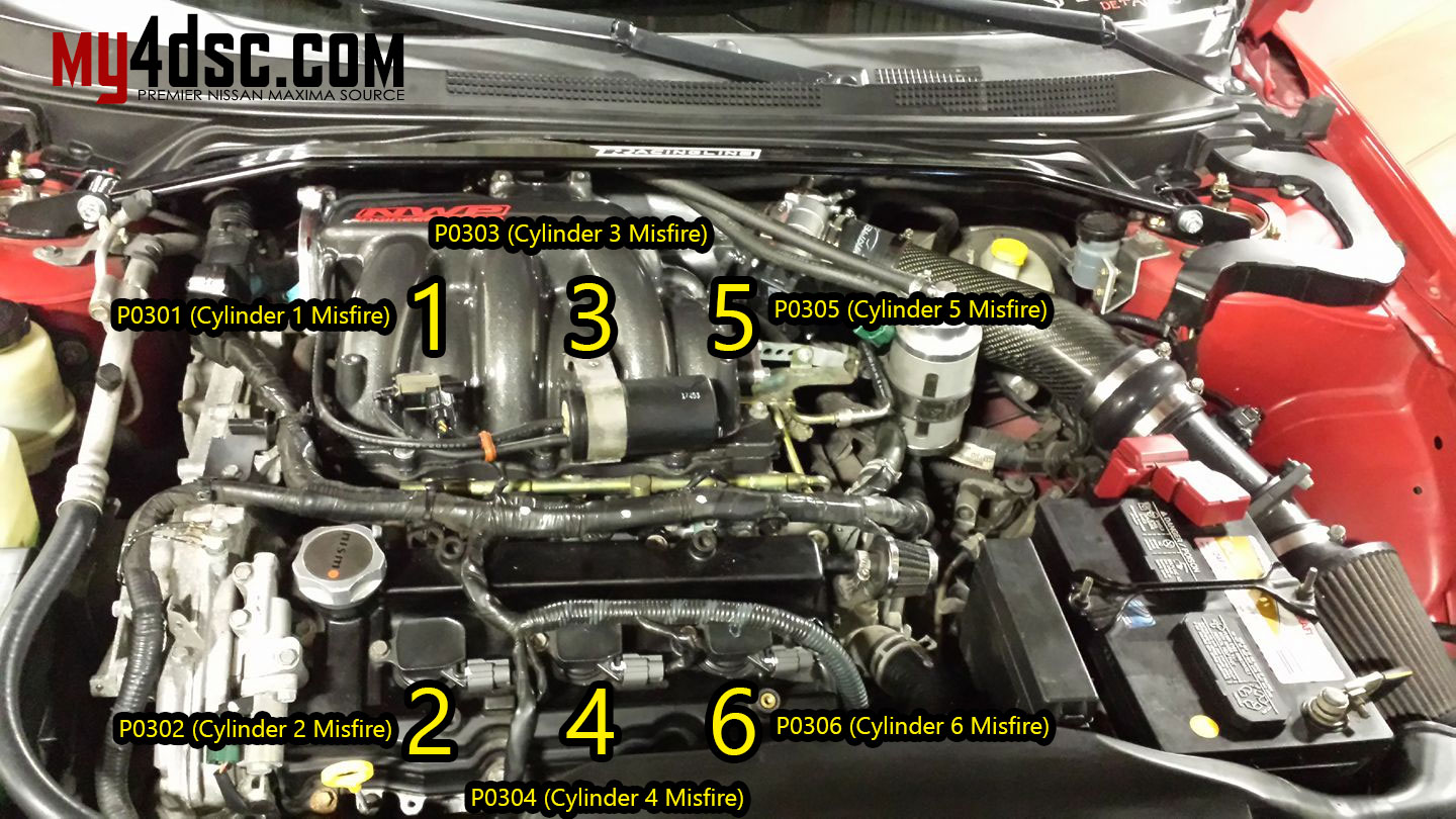
If you have a CEL for random misfire, below the common codes.
FSM Photo:


If you are installing a turbo or supercharged setup in your Nissan Maxima, you will need an oil feedline hooked up to your car. Below is the one I’m using in my Supercharged 5thgen Nissan Maxima. Works well and have had zero issues.
Order Links:


Community Member Credit: R&D Factory
Here are DIY instructions on how to replace the OEM seals on your Nissan VQ engine.
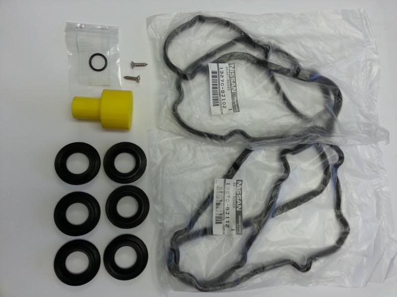
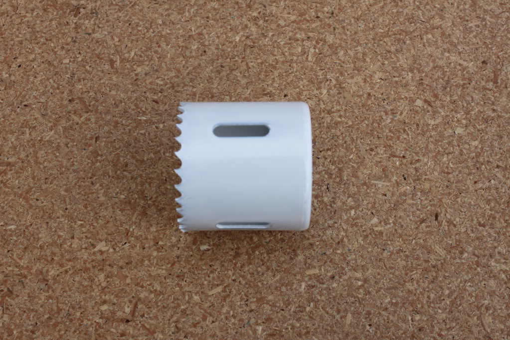
At R&D Factory, we service many Nissans and Infiniti’s daily and run into the same valve cover/spark plug o-ring leak. About 75% of the vehicles that we serve have the same problems. Even though it’s money out of customer’s pocket after spending so much money on these valve covers we were thinking there has to be a way to cut the cost so here we are. R&D has come out the kit will come with both driver and passenger side valve cover gasket, six o-ring gaskets, and simple instructions on how to replace them. Your warranty should and will cover leaking valve cover o-rings grommets. we do advise you to check for a leak before your warranty is over…. the whole idea of us making these o-rings grommets were for those who have leaking o-rings grommets yet their warranty is already over. We do drill out the old o-ring grommets with the hole saw size 2 inch. It is slightly bigger than the existing hole and slightly smaller than the o-ring
$75 for 6 Grommets (O-ring gasket)
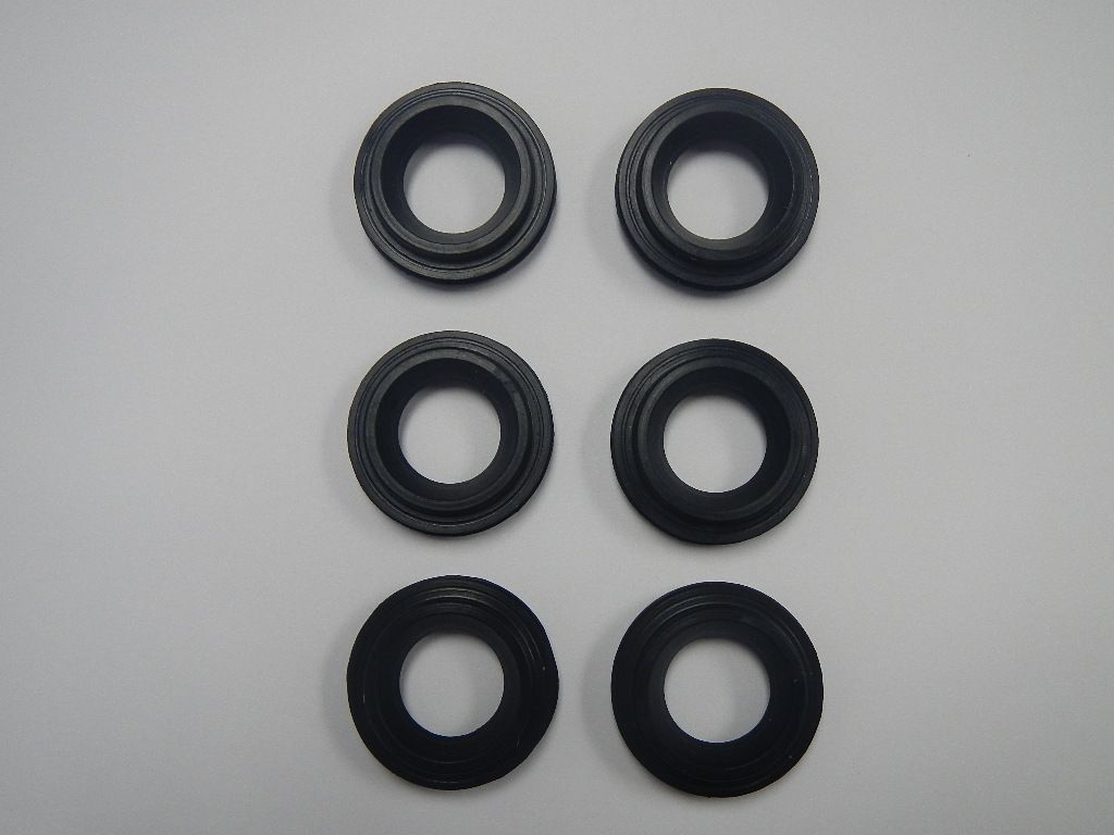
$120 for 6 Grommets (O-ring gasket) and OEM valve cover gaskets (both side), PCV Valve o-ring
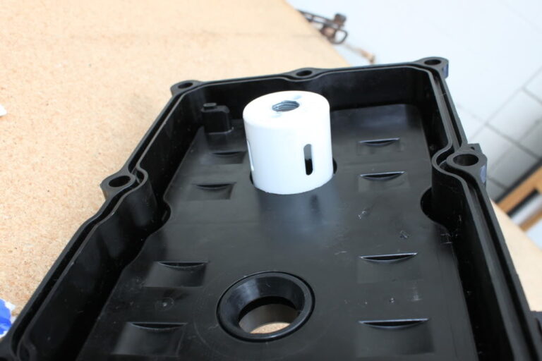
1- THIS IS A SIMPLE HOLE SAW (SIZE 1 7/8 INCH) THAT YOU CAN BUY FROM MOST HARDWARE STORE. WE GOT OURS FROM ACE HARDWARE AND IT WAS $7-11
2- THIS IS HOW YOUR VALVE COVER LOOKS WHEN YOU TAKE IT OFF OF YOUR ENGINE

NOTE PICTURE SHOWN MOST LEFT SPARK PLUG HOLE DRILLED.
3- WARNING “PLEASE DO NOT REMOVE BAFFLE PLATE” WARNING

4- POSITION THE HOLE-SAW CONCENTRIC TO SPARKPLUG HOLE AND DRILL BAFFLE PLATE SLOWLY AND CAREFULLY.


5- YOU WILL ONLY NEED TO DRILL JUST ENOUGH TO DRILL THROUGH THE BAFFLE PLATE (WE CLEANED UP ALL THE DEBRIS TO SHOW YOU CLEAR PICTURE DRILL ALL 6 POSITIONS AND CLEAN OFF DEBRIS WHEN DONE.
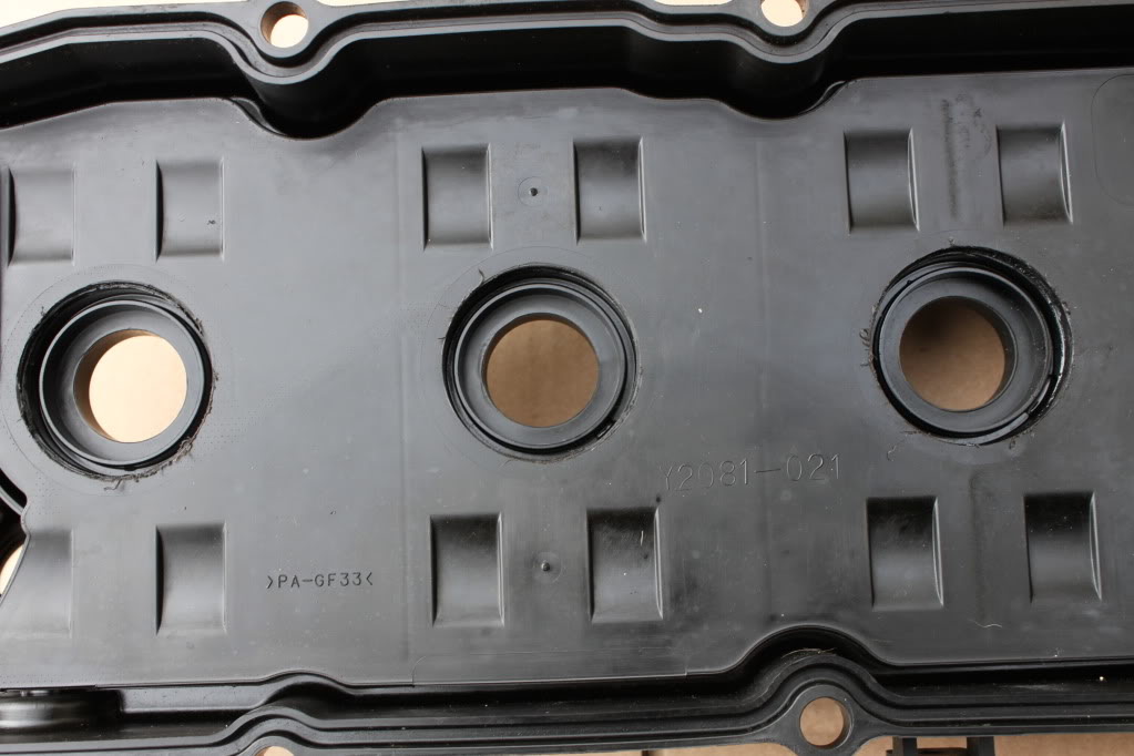
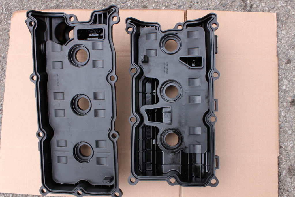
6- NOW YOU WILL BE ABLE TO POP OUT THE OLD O-RING GROMMET OUT OF THE VALVE COVER. PLEASE REPEAT 6 TIMES.

7- THIS IS WHAT IT WOULD LOOK LIKE WITH THE O-RING GROMMET OUT
8- USE BLACK RTV SILICONE ON TOP SIDE OF THE NEW O-RING GROMMET (WE USED CLEAR ON OUR DEMO PICTURE SO YOU CAN SEE BETTER)

9- PLACE THE NEW O-RING GASKET IN TO THE HOLE. NOW YOU ARE READY TO RE-INSTALL YOUR VALVE COVER GASKET TO YOUR ENGINE.


