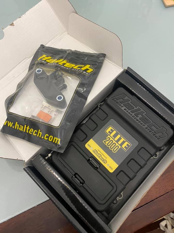
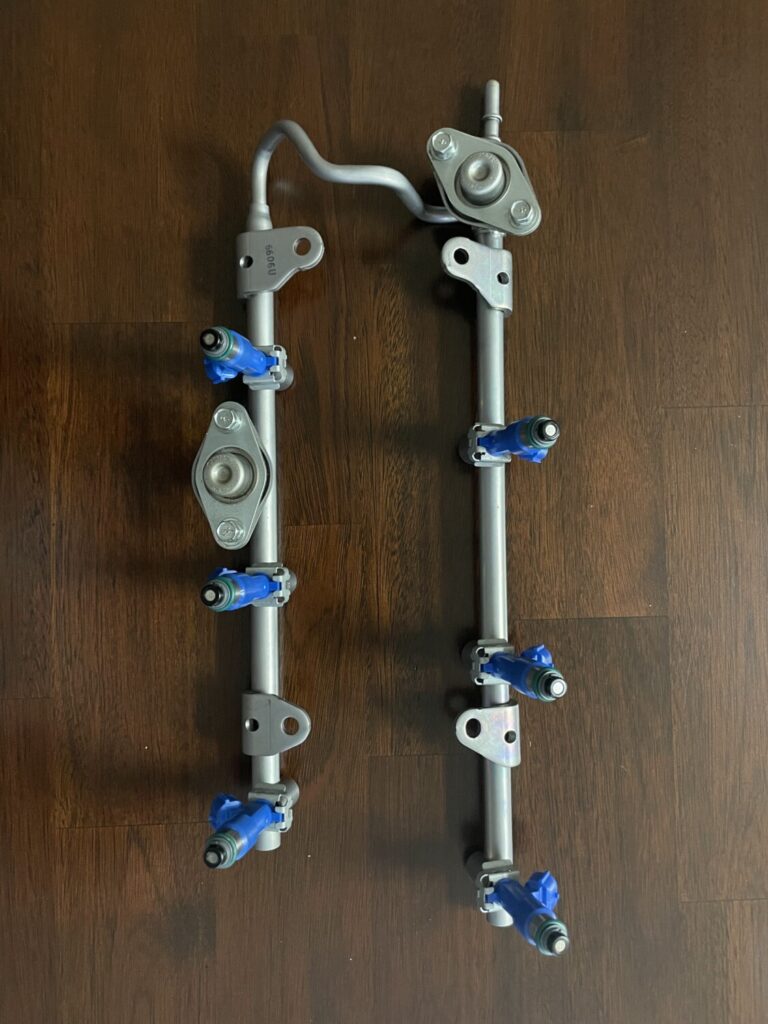
Community Member Credit: Voltaire Duran Cacal
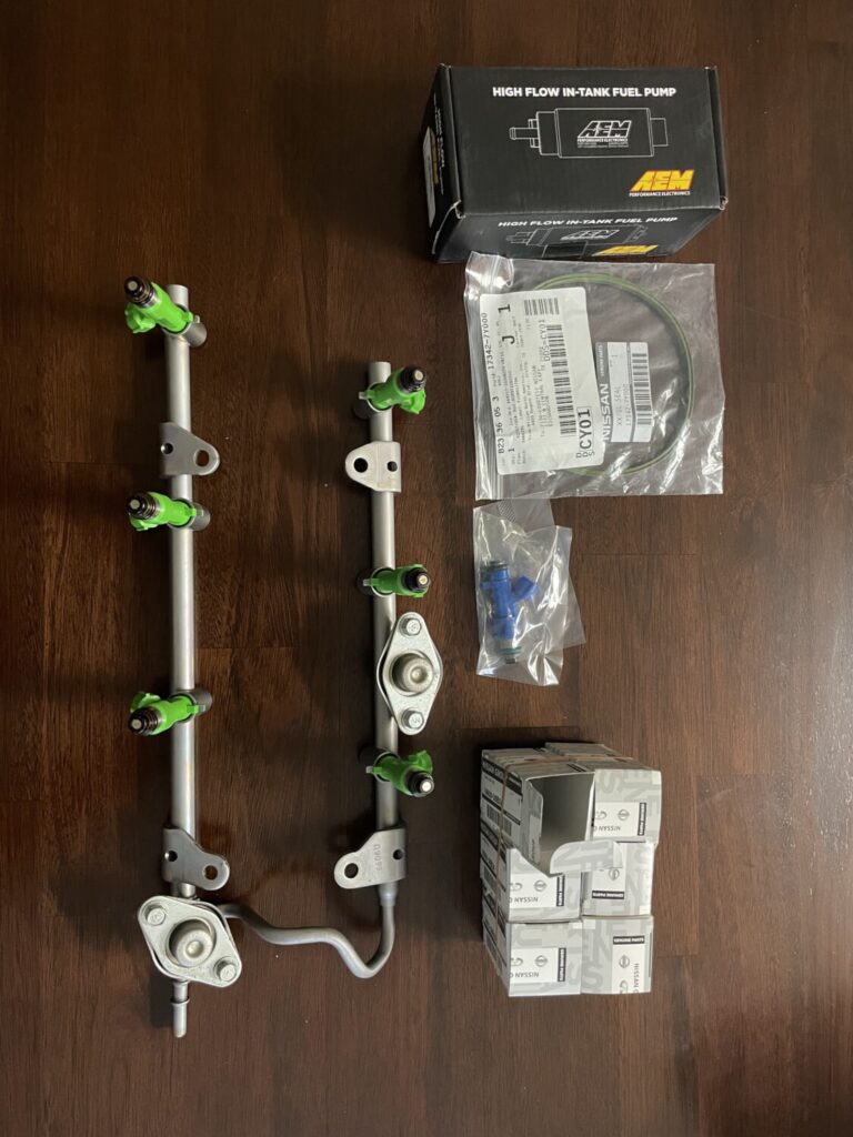
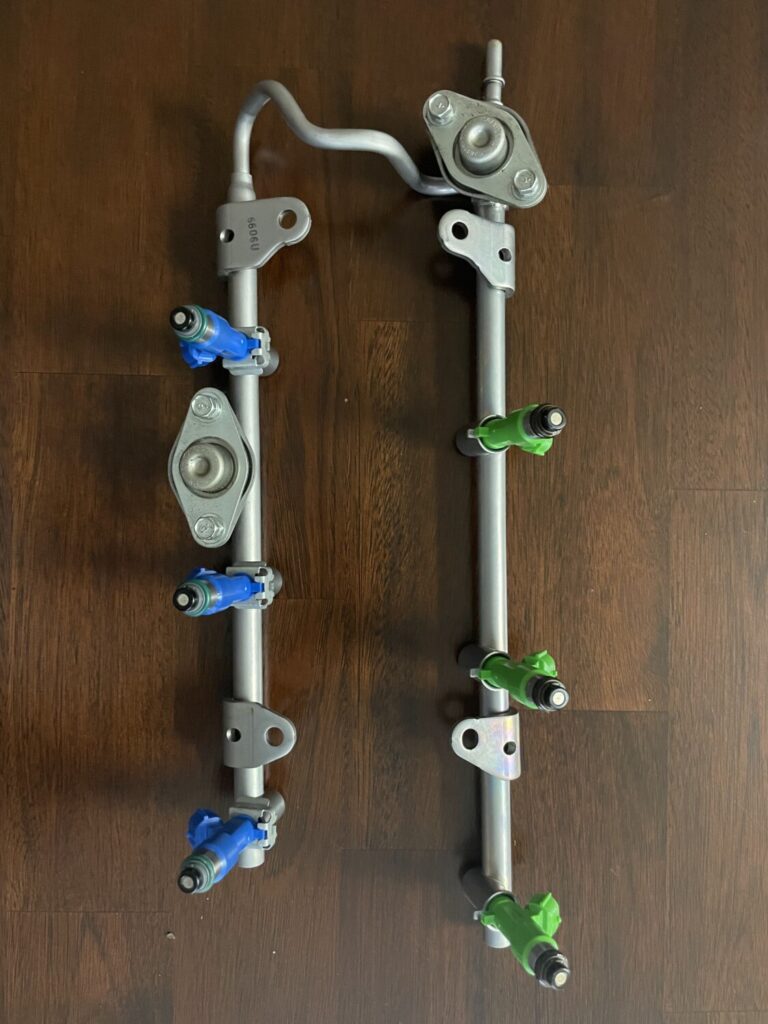
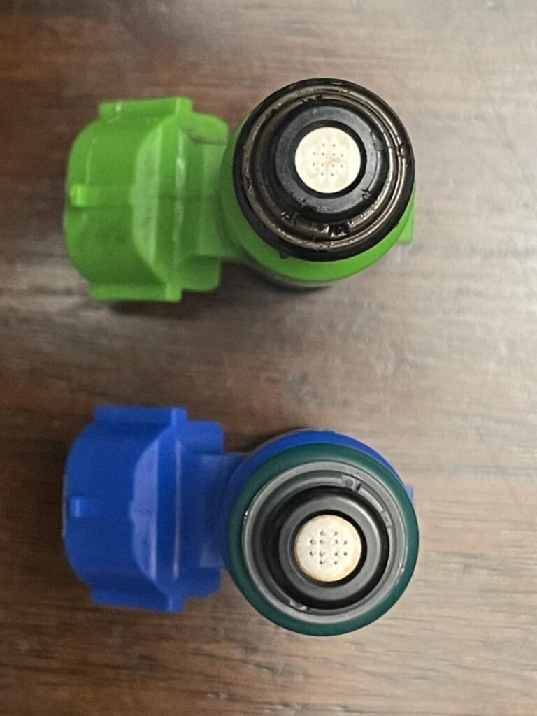



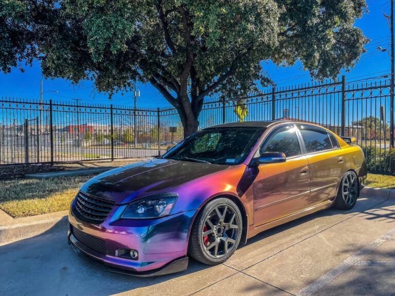

Community Member Credit: Jose Vargas
Order Link: https://www.chasebays.com/collections/universal-chase-bays/products/chase-bays-windshield-washer-reservoir-intercooler-sprayer
Price: $119.99
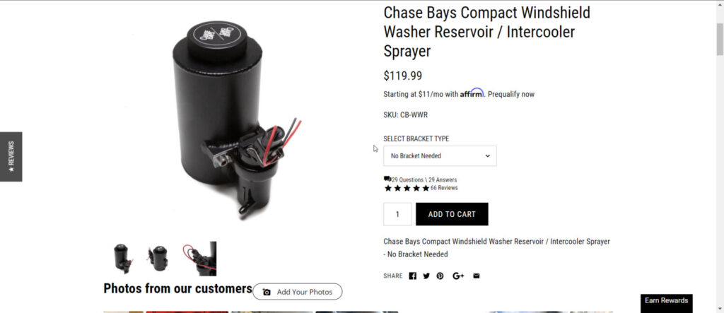
OEM Wires
Chase Bay Pump Wires
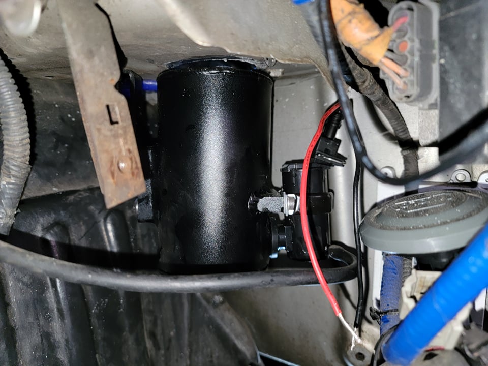
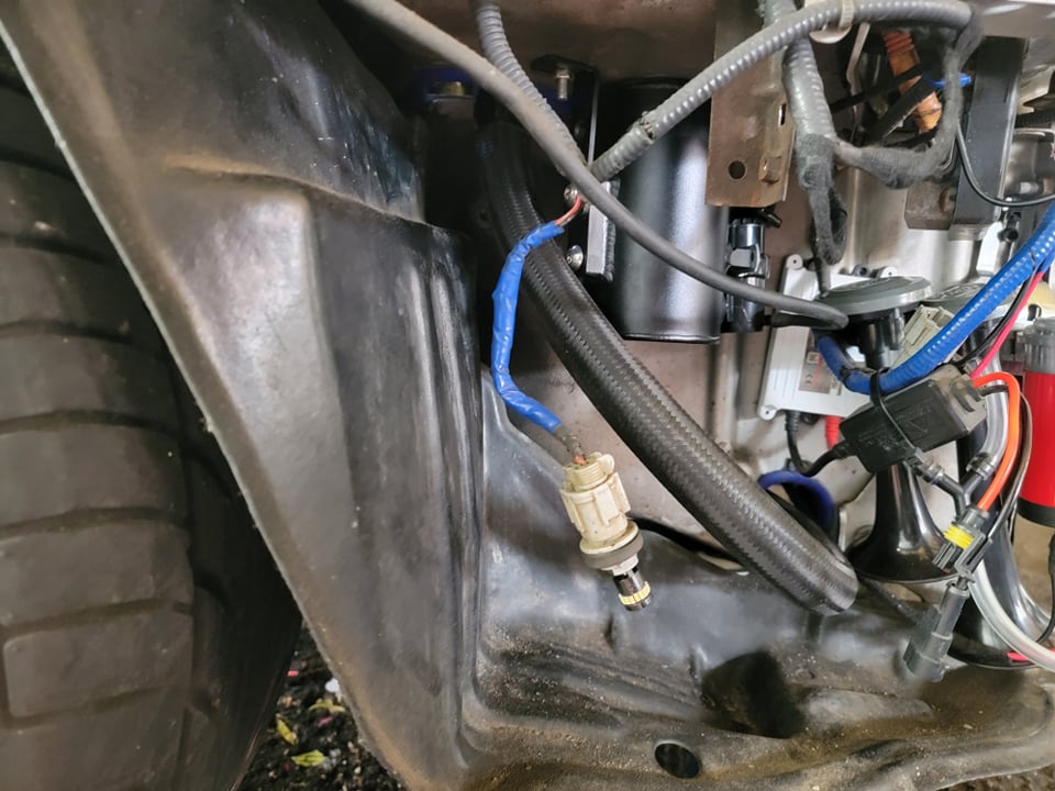
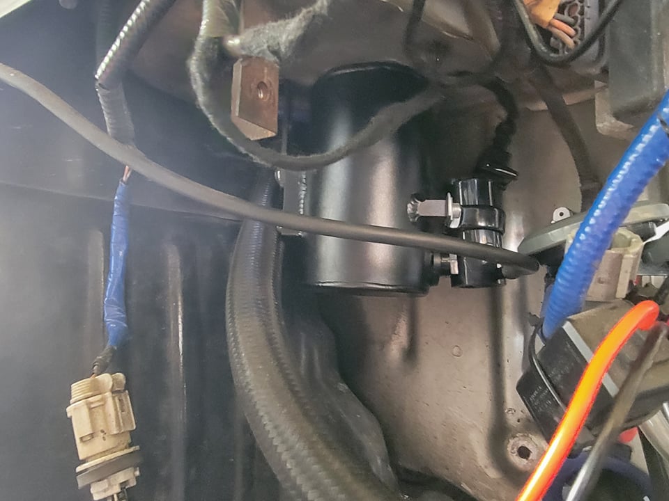


Community Member Credit: CS_AR
Today I finished refurbishing the metal water pipes that run along the left side (e.g. nearest the radiator) of the engine.
After sanding and refinishing the pipes, I used some ceramic VHT exhaust header primer and paint that I had leftover from the Y-pipe. I’ve been slowly baking the pipes this afternoon to cure the ceramic paint before I do the installation. I’ve got to make sure the ceramic paint is fully cured and hardened before installing the o-rings and heater hoses. I did have to spend quite a bit of time sanding and polishing the hose connection areas to smooth off some rust that had formed between the hose rubber and the pipe. We’ll see how well the refinished hose and o-ring connection areas will hold up over time. The pipes are now in better condition than when I started.
Here are a couple of pictures that we may want to reference when someone has a water leak or needs to replace the o-rings or gasket. I like the Felpro gasket with the extra “red seal” area for the aluminum hose manifold mating surface. In the end, I reused some OEM o-rings that I already had on hand. I recommend using OEM o-rings as they will be the correct size.
I used 0000 steel wool to polish the aluminum pipe manifold o-ring and gasket mating surface areas. I might have been better off buying some new OEM pipes that come with a factory powder coat. But we can see how long the refurbished pipes last in the meantime.
Pardon my phone camera, as the pipes are actually a silver metallic color that matches the aluminum pipe manifold part.


Here are a couple of pictures with the refinished pipes on the car. Valve cover polishing was still a work in progress when I took a break to snap the following picture.

I changed the 10mm short bolts pipe mounting bolts to use hex cap heads with lock washers in the picture.

Refinishing the pipes baking the ceramic paint has been a small project in itself. The only reason I attempted it is the easy-to-reach location if something backfires on me. A
s a side note, the OEM heater supply pipe on a VH45DE comes nickel-plated from Nissan. So all I had to do when I got a new one was to polish it up a bit and then clear coat it for the long haul. On a VH45DE the pipe lives at the bottom of “death valley” buried under a Gordian Knot of hose and wiring harnesses. You don’t want to miss anything that could come back as a leak or a problem after you put one of those critters back together. You can see it in the picture below the supply pipe running underneath the short pieces of head coolant hose.

Here are a couple of pictures with the refinished pipes on the car. I sure hope the o-rings hold up. The pipes felt solid and I could tell the o-rings were sealing the connections.
Valve cover polishing was still a work in progress when I took a break last night to snap the following picture. More to come with engine details about the coolant crossover pipe.

The original 10mm mounting bolts were changed to use stainless hex cap heads with lock washers in this picture. If possible, I like to use this type of bolt for coolant and fuel connection bolts.

Fortunately, the 99 model (with a 95 model engine) where I refinished the pipes, had under 80,000 miles. I didn’t notice any rust on the inside of the pipes. The pipes came with an engine from a local car that had been in a bad rear end collision. I bought the motor and had it installed in the 99 model.
This year, I took the pipes from the 99 model’s original engine with under 170,000 miles and refinished them for the 98 model with over 235,000 miles.
There is a 2nd thread on this topic, where I refinished the pipes from the 98 model. Those pipes are some of the worst that I’ve seen to date. In the time frame for the 98 model project, I discovered soaking metal parts in muriatic acid removes rust in a hurry.
I think the quality of water that is mixed with anti-freeze to make coolant has a lot to do with the formation of rust or barnacles in a cooling system.
The 98 model lived in a part of the state when iron deposits in the water so high that people use water softeners to condition the water for indoor use. The iron content in that area’s water will stain plumbing fixtures unless the water is conditioned before use. I could see that in the cooling system when I had it open.
One of my cars, lived for many year in a part of TX that must have had a lot of sulfur or calcium in the water. I found crusty mineral deposits inside its cooling system.
Even though the area where I live has good water that does not require conditioning before use, I like to use a 50/50 mix of distilled water and Xerex G05. After seven years of use on all of my Nissan products, it seems to work.
So here’s a picture of the acid bath where I cleaned up some pipes and put them away in my workshop for another project. Naturally, some light surface rust has appeared on the freshly cleaned pipes because I didn’t prime and refinish. I have an EGR pipe that I will treat sometime later in the year. I have another VQ30 from an I30 that I will be semi-overhauling to have on the shelf in the event I need a replacement engine.

Here’s a picture of the pipes that were refinished in this thread almost 3 years later. I am satisfied with how they are holding up. No surface rust, no complaints, and low maintenance.


I see a coolant flush product advertised for removing rust. This seems to be more popular with iron block engines.
If you find one that you think is safe to use on an aluminum engine, you might try it. One thing to note is acid and aluminum do not get along very well.
An aluminum part that is submerged in a muriatic acid bath that is strong enough to remove rust from metal parts, will fizz like an effervescent tablet. You can watch your part turn dark and start to dissolve right before your eyes. So I would use caution with a coolant flush that was designed for iron block engines that contains a lot of acid.
On one aluminum engine car, I used vinegar like the guy in this video. Though I followed it up two or three distilled water flushes to neutralize the vinegar before refilling with Zerex.
Many years ago I would see some coolant flush products shorten the life of water pumps. So I’ve always been hesitant to use a lot of chemicals to flush a cooling system.


Member Credit: Rob
1. General Overview
If you can install a car alarm, you can install this kit. However, if you make a mistake, it may render your car undriveable. Please take your time and following all the test procedures listed in the installation guide.
Disclaimer: Because this is a do it yourself modification, I will not be responsible for either the INSTALLATION, USE, or FUNCTION of this kit. Proceed with caution and at your own risk. This kit is for OFF-ROAD use only.
1.1 Kit Contents
The kit includes:
* A. Manumatic Controller Box
* B. Power Cable
* C. Control Cable (7 ft)
* D. Relay Module
* E. Remote LED Display and Cable (optional, 7ft)
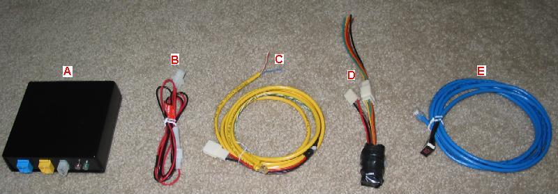
Figure 1. Kit Contents
1.2 Equipment Needed
* philips screwdriver
* wire cutter / wire stripper
* electrical tape
* solder gun and solder
* double sided tape
You must solder all wire connections for solid contacts.
1.3 Connector Locations
There are only 2 areas of the car where we need to perform wire cutting and splicing.
The first area is the ASCD Connector (M30). The ASCD connector is out in the open, located near the driver’s right knee (shown below).

Figure 2. ASCD Connector
The second area is the TCM Connectors. For the 1998-1999 Maxima, there are 2 TCM Connectors (F109 and F108, shown in Figure 3a below). The TCM Connectors are accessible by removing the ashtray assembly. F109 is on the left and F108 is on the right.

Figure 3a. TCM Connectors in 1998-1999 Maxima (F109 on left, F108 on right)
For the 1995-1997 Maxima, there is only 1 TCM Connector (protected by a bolt shown in Figure 3b below). The TCM Connector is accessible by removing the ashtray assembly. Thanks go to Eric W. for tracking down the following images and diagrams.

Figure 3b. TCM Connector in 1995-1997 Maxima
1.4 Kit Layout
The following diagram shows the recommend layout of the kit’s components.

Figure 4. Kit Layout
The Manumatic Controller Box is placed under the driver’s seat. The Relay Module is taped to the inside of the dash. Where to put the optional “Remote LED Display” is left up to you.
1.5 Wire Colors
The following table shows color codes used to represent different wire colors.
B = Black
W = White
R = Red
G = Green
L = Blue
Y = Yellow
G = Light Green
BR = Brown
OR = Orange
P = Pink
PU = Purple
GY = Gray
Figure 5. Wire Colors
When the wire color is striped, the base color is given first, followed by the stripe color as shown below:
Example: L/W = Blue with White Stripe
1.6 Wire Modifications
We will be making wire connections in 2 different ways: tapping and highjacking.
Tapping a wire involves the addition of a new wire to an existing wire. The existing wire must NOT be cut. The following diagram shows a before and after picture.

Figure 6. Tapping an Existing Wire
Highjacking a wire involves the cutting of the existing wire and attaching 2 new wires to the cut ends. The following diagram shows a before and after picture.
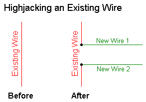
Figure 7. Highjacking an Existing Wire
2.0 Installation
The installation should take you one day. The instructions will start by asking you to remove/loosen interior trim pieces to bring the work areas into view. Try to get to know where the wires and components will go before installing anything. During the installation, there will be tests which you should run to help verify proper installation. Install the Remote LED Display last in case you run out of daylight (since it’s optional).
2.1 Accessing the TCM Connectors
Start by removing the shifter trim and then the ashtray assembly (shown in figure below).

Figure 8. Dash Trim Removal
Lift the shifter trim and then pull it towards you. Remove the power plug for the cigarette lighter and set the shifter trim aside. Remove the single screw holding the ashtray assembly in place. Pull the ashtray assembly out (it’s now held in place by 1 clip on the right side). Remove the ashtray light plug and then set the ashtray aside.
The TCM should now be visible. Unplug the TCM connector(s) (see Figures 9a and 9b shown below). We will connect wires to these connectors later. If your hands are too big or if you are claustrophobic, then remove the stereo for more space to work in.

Figure 9. TCM Connectors in 1998-1999 Maxima (F109 on left, F108 on right)
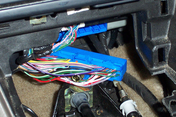
Figure 9. TCM Connector in 1995-1997 Maxima
2.2 Loosen Center Console
You only need to loosen the center console to run the cables from under the driver’s seat to the dash. Start by removing the top 2 screws on the center console (shown below).
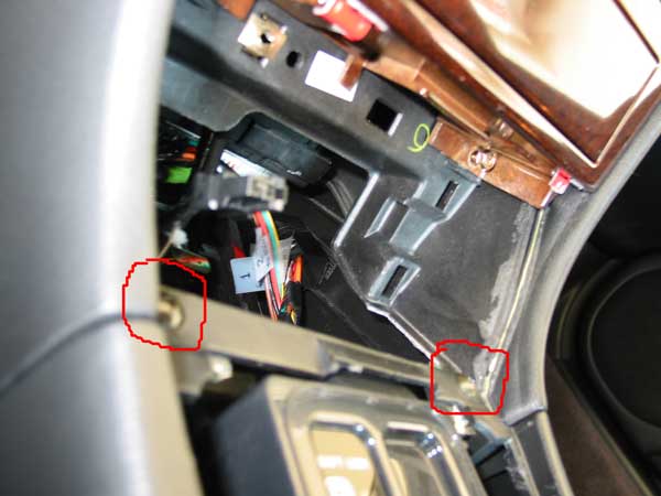
Figure 10. Center Console Screws – Top Front
Next, remove the 2 screws in the back of the center console (1 on either side).
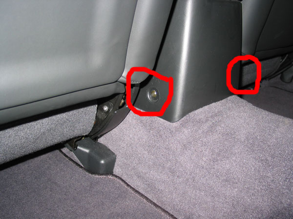
Figure 11. Center Console Screws – Bottom Rear
2.3 Install Cables
Try to visualize where all the wires and components will go before installing cables.
When you are ready to begin, locate the controller (yellow), display (blue), and power (red/black) cables (see Figure 1). Each cable should have a connector on one end and bare wires on the other end.
Start by placing the connector end of all 3 cables under the driver’s seat. Route the cables under the seat rail into the center console. Tie the cables so that moving the seat does not cut the wires.
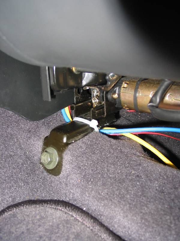
Figure 12. Put Cable Connectors Under Driver’s Seat
Next, route the cables along the center console towards the dash (shown in the following 2 pictures). Tie the cables to the existing wires running along the center console.

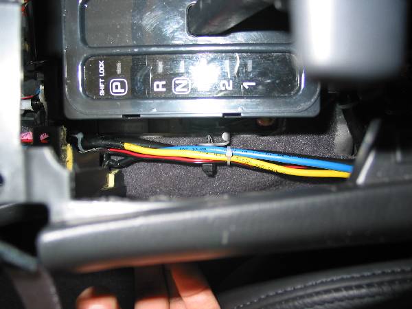
Figure 13. Route Cables Through The Center Console Towards The Dash
The power cable ends in the dash where we will, later, connect it to the cigarette lighter.
Route the remote LED display cable (blue) through the dash and out the back of the dash (towards the gas pedal). We will mount the remote LED display last.
The controller cable (yellow) splits at the dash. Some wires will stay in the dash (for connection to TCM and relay module) while the rest will go through the back of the dash (for connection to ASCD).
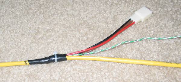
Figure 14. Yellow Cable Split
Splitting from the yellow cable is a 3 pin connector. This will be connected to the relay module. Also splitting from the yellow cable are 2 wires (green, white/green) which will be connected to the TCM. Route the remainder of the yellow cable through the back of the dash. These wires will be connected to the ASCD control unit.
2.3 Connect ASCD Wires
The following diagram shows the ASCD connector, as-is. On this connector, we are only interested in 3 wires (pin 1 – Accel, pin 2 – Coast, pin 4 – Cruise). Make sure you identify the wires by both its color code and its relative location to other wires.

Figure 15. ASCD Connector Pinout
First, locate the green/orange “Accel” wire (pin 1 of ASCD connector). Next, locate the orange/white wire in the yellow control cable. We will tap into the “Accel” wire by connecting the orange/white wire to the green/orange wire (show below). Be sure to solder all connections together.

Figure 16. Modified ASCD Connector
In a similar fashion, we will tap into the “Coast” wire (pin 2 of ASCD connector) by connecting the orange wire from the control cable to the green/yellow wire.
Finally, tap into the “Cruise” wire (pin 4 of ASCD connector) by connecting the blue wire from the control cable to the green/white wire.
2.4 Connect Relay Module Wires
Start by unplugging the wires connected to the relay module (shown in figure below). We will connect these wires to the TCM. Later, we will plug the connector end back into the relay module.

Figure 17. Relay Module Wires
For 1998-1999 Maximas, follow the instructions in section 2.4.1. For 1995-1997 Maximas, follow the instructions in section 2.4.2.
2.4.1 Connect Relay Module Wires to 1998-1999 Maxima
The following diagram shows connector F109, as-is. On this connector, we are only interested in 3 wires (pin 26, 27, and 34). Make sure you identify the wires by both its color code and its relative location to other wires.

Figure 18. F109 Connector Pinout
Locate the Yellow/Blue wire on F109 (pin 34). Now locate the green wire and the yellow wire on the relay cable. We will highjack pin 34 with these 2 wires. Start by cutting the Yellow/Blue wire (pin 34). Connect the green wire to the half coming from the gearshifter. Connect the yellow wire to the half going towards the TCM (F109).
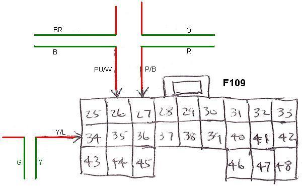
Figure 19. Modified F109 Connector
In a similar fashion, we will highjack pin 26 on F109 (Purple/White). Start by cutting the Purple/White pin 26 wire. Connect the brown wire to the half coming from the gearshifter. Connect the black wire to the half going towards the TCM (F109).
Lastly, highjack pin 27 on F109 (Pink/Black). Start by cutting the Pink/Black pin 27 wire. Connect the orange wire to the half coming from the gearshifter. Connect the red wire to the half going towards the TCM (F109).
2.4.2 Connect Relay Module Wires to 1995-1997 Maxima
The following diagram shows the TCM connector, as-is. For now, we are only interested in 3 wires (pin 16, 17, and 18). Make sure you identify the wires by both its color code and its relative location to other wires.
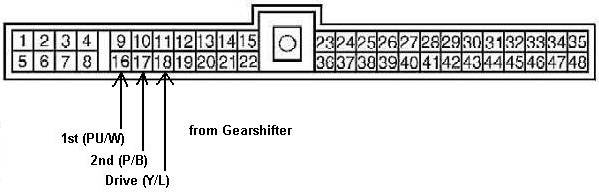
Figure 18. TCM Connector Pinout for 1995-1997 Maxima
Locate the Yellow/Blue wire (pin 18). Now locate the green wire and the yellow wire on the relay cable. We will highjack pin 18 with these 2 wires. Start by cutting the Yellow/Blue wire (pin 18). Connect the green wire to the half coming from the gearshifter. Connect the yellow wire to the half going towards the TCM.
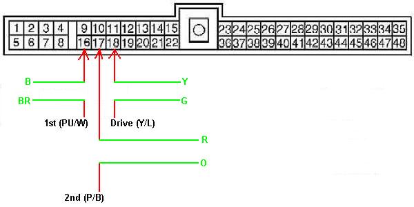
Figure 19. Modified TCM Connector Pinout for 1995-1997 Maxima
In a similar fashion, we will highjack pin 16 (Purple/White). Start by cutting the Purple/White pin 16 wire. Connect the brown wire to the half coming from the gearshifter. Connect the black wire to the half going towards the TCM.
Lastly, highjack pin 17 (Pink/Black). Start by cutting the Pink/Black pin 17 wire. Connect the orange wire to the half coming from the gearshifter. Connect the red wire to the half going towards the TCM.
2.5 Connect Remaining TCM Wires
We only need 2 more wires on the TCM connector(s). For 1998-1999 Maximas, see section 2.5.1. For 1995-1997 Maximas, see section 2.5.2.
2.5.1 Connect Remaining TCM Wires on 1998-1999 Maxima
The following diagram shows the F108 connector, as-is. On this connector, we are only interested in 2 wires, pins 13 and 22. Make sure you identify the wires by both its color code and its relative location to other wires.

Figure 20. F108 Connector Pinout
First, locate pin 13 on F108 (White wire). Next, locate the Green/White wire from the yellow control cable. We will tap into the pin 13 by connecting the green/white wire to the white wire (show below).
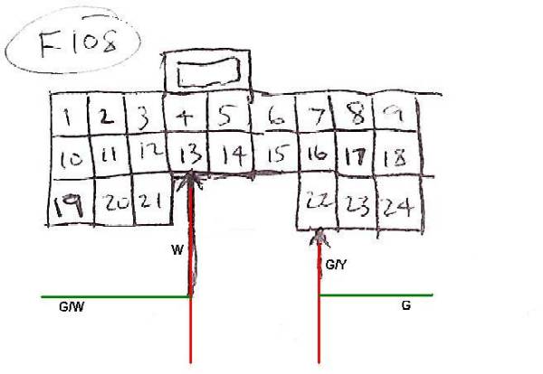
Figure 21. Modified F108 Connector
In a similar fashion, we will tap into pin 22 on F108 (Green/Yellow) by connecting the green wire from the control cable to it. Be sure to solder all connections together.
2.5.2 Connect Remaining TCM Wires on 1995-1997 Maxima
The following diagram shows the next 2 wires on the TCM connector that we will be working on (pins 3 and 39). Make sure you identify the wires by both its color code and its relative location to other wires.

Figure 20. Original OD Wires on TCM Connector for 1995-1997 Maxima
First, locate pin 3 (White wire). Next, locate the Green/White wire from the yellow control cable. We will tap into the pin 13 by connecting the green/white wire to the white wire (show below).

Figure 21. Modified OD Wires on TCM Connector for 1995-1997 Maxima
In a similar fashion, we will tap into pin 39 (Green/Yellow) by connecting the green wire from the control cable to it. Be sure to solder all connections together.
2.6 Connect Power Wires
Only 2 more wires to go. Locate the cigarette plug which we discounted earlier.

Figure 22. Cigarette Plug
We’ll tap power and ground from this plug (connector). Locate the supplied power cable (red and black wire). Connect the red wire from the power cable to the Orange/Black cable in the cigarette plug. Connect the black wire from the power cable to the Black cable in the cigarette plug.
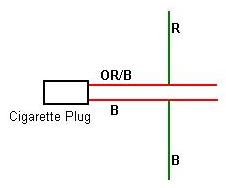
Figure 23. Modified Cigarette Plug
2.7 Connect the Relay Module
Plug the relay module into the matching 6 pin connector that you wired in section 2.4. Plug the 3 pin connector on the relay module into the matching 3 pin connector on the yellow control cable. Use some double sided tape to hold the relay module to the inside of the dash.
This is a good time to make sure your car still works as before. First, tie down all the cabling and set the center console in its normal place so that nothing interferes with the gearshifter. Plug the F108, F109, and the ASCD connectors back into their normal place. Start the car and check that the “D”, “2”, and “1” gear positions still work as before.
2.8 Test For Power
Let’s first check for proper power up of the manumatic controller box. Connect the power cable to the Manumatic Controller.
Turn the ignition to the ON position (but do not start the car). Make sure the RED led on the Manumatic Controller box turns on (has power).
2.9 Connecting Everything and Final Testing
Connect the yellow controller cable to the yellow connector on the manumatic controller box. Next, connect blue remote LED display cable to the blue connector on the controller box. For now, just leave the LED display somewhere visible to you while you are driving. Leave the controller box under the seat.
We are now ready to perform more tests. The following test will check to make sure the manumatic can cycle through the gears.
1. Make sure the gearshifter is in “Park”. Turn the ignition to the ON position (but do not start the car). The remote LED display should be OFF.
2. Press the middle button on the cruise cluster located on your steering wheel. The remote LED should still be OFF.
3. Put the Gear Selector in Drive (you will need to push the brake pedal in order to move the gear selector out of park). The remote LED should still be OFF.
4. Press the middle button on the cruise cluster located on the steering wheel. The remote LED should turn ON (displaying the number 3). Note that the OD OFF light in your instrument cluster should be ON.
5. Press the down button (bottom button on the cruise cluster). The remote LED should now display the number 2. Keep pressing the down button until the display cycles to 1. It should not go lower than 1. Note that the OD OFF light should still be ON.
6. Press the up button (top button on the cruise cluster). The remote LED should count up from 1 to 4. When you reach 4, the OD OFF light should turn OFF.
7. Press the middle button again. The remote LED display should turn OFF.
8. Put the gearshifter in “Park”, turn the ignition OFF, and remove the key.
If you pass the above test, then we’ll check that the manumatic is properly disabled when the gearshifter is not in Drive or when cruise control is ON.
1. Turn the ignition to the ON position (but do not start the car). The remote LED display should be OFF.
2. Put the Gear Selector in Drive (you will need to push the brake pedal in order to move the gear selector out of park). The remote LED should still be OFF.
3. Press the middle button on the cruise cluster located on the steering wheel. The remote LED should turn ON.
4. Shift the gear selector out of “Drive”, the remote LED should turn OFF.
5. Press the middle button again. The remote LED display should still be OFF.
6. Shift the gear selector back to “Drive”.
7. Press the middle button again. The remote LED display should turn ON.
8. Press the “Cruise On” button located on your dash (next to the security LED). The remote LED display should turn OFF.
9. Press the middle button again. The remote LED display should still be OFF.
10. Put the gearshifter in “Park”, turn the ignition OFF, and remove the key.
If you pass the above test, then you’re ready for a real driving test. Cautiously drive the car, in auto mode, to an empty parking lot or open space. From there, turn on manual mode and check for the following:
1. When in 1, the car does not shift up to 2,3,4 no matter what rpm.
2. When in 2, the car does not shift up to 3,4 no matter what rpm. Note that the car may shift down to 1 if going too slow.
3. When in 3, the car does not shift up to 4 no matter what rpm. Note that the car may shift down to 1,2 if going too slow.
Functionally, you’re done. From now on, you the buttons on the steering wheel to change gear selections when in manumatic mode. Do not use the gearshifter button (OD OFF) when in manumatic mode. It took me a few days to get used to keeping my right hand on the steering wheel.
2.10 Mounting the Optional Remote LED Display
The only thing left at this point is to mount the optional “Remote LED Display”. This step has been left to you to decide because your choice of where to install it determines the difficultly level.
Mounting the display inside the instrument cluster is the most difficult. Cheston has an excellent guide on how to access the instrument cluster.
How to Install Indiglo Dash Gauges
2.11 Maintenance
The only thing that may need replacement is the fuse located along the power cable. If it’s blown, replace it with a similar sized .5 amp 12v fuse. If it blows constantly, there maybe a problem with your car or with the manumatic controller.
3.0 Manumatic Operation
This modification gives older Maximas a “manumatic mode” similar to that found on newer cars. It’s a pretty simple concept and it’s operation is described below:
* Manumatic Mode is only available while the gearshifter is in “Drive” and the Cruise Control is OFF.
* Manumatic Mode is automatically turned OFF and disabled when you leave “Drive” or turn Cruise Control ON.
* Manumatic Mode reuses the cruise cluster buttons on your steering wheel to change gear selections.
* The middle button on the cruise cluster turns the manumatic on and off. The top button shifts up. The bottom button shifts down.
* Car will not shift into a higher gear than the gear displayed by the manumatic. For example, when it displays “2”, the car will not shift to 3 or 4.
* Car may shift into a lower gear than the gear displayed by the manumatic. For example, when it displays “2”, the car may shift to 1 if you are going too slow.
* You car will continue to work in auto mode, as before, if you remove the manumatic controller box (or if it loses power).
There’s not much to it when it comes to operation. Here’s more information I posted on maxima.org:
I’m glad other people are interested. I mainly did this
for myself and I spent a lot of time on the design. The main
criterias were:
—
SAFETY:
1. If the board loses power or is disconnected, your car’s auto
mode still works unchanged.
2. MMode is only available in “D” (you can toggle it on or off
at the steering wheel). If you shift out of “D”, then MMode is
automatically turned off and disabled.
3. If you turn on Cruise control, MMode is automatically turned off and disabled.
4. Shifting to a lower gear than your speed/engine allows will
result in a delayed shift, rather than your tranny dropping to the
ground (gears include 1,2,3,4).
—
KISS (keep it simple stupid):
5. Minimize the number of wires needed to installed and places
where you need to install them. Basically, you splice/highjack:
– 5 wires in the TCM connector (accessible behind the cigarette tray)
– 3 wires in the ASCD connector (out in the open, near your right knee)
– and finally, 12v and ground (which I take from the cigarette lighter)
—
STOCK LOOK (no radio shack switches poking out everywere)
6. Reuses existing cruise control buttons when in “D” and when cruise
is OFF. Middle button toggles MMode on/off. Top button goes up in
gear and bottom button goes down in gear. When cruise is on, buttons
act as normal cruise control buttons (MMode is automatically turned off
and disabled when cruise control is on).
7. The remote LED display is optional. You don’t have to have it.
If you want it, you can place it anywhere. Putting it in the instrument
cluster is the most stock looking but quick frankly, that was the hardest
part of the install.
—
Basically, MMode shifts the gear selector and controls OD for you.
No more accidental shifts into neutral. No more looking at the gear
selector to see where it is. No more micromanaging of “OD Off” button.
Here’s an example use:
– start car
– select “D” with existing gear selector
– drive somewhere
– press middle button to turn MMode on (Remote LED turns on)
– press down, up, down, down, up, up, etc…
– press middle button again to turn MMode off (Remote LED turns off)
Remember, changing the gear selector out of “D” or turning on Cruise
will turn off and disable MMode.
Read more: http://my4thgen.org/showthread.php?t=177#ixzz4VDZuUCaa
Community Member Credit: gtrrider
Basing our review on a 1995 Nissan Maxima, this application seems best for such a product in terms of providing restoration of needed grounding points and also slightly dressing up the engine bay. ActiveTuning prides themselves on this kit because it has been slightly revised recently with some added improvements ranging from: 1666 High Strand Count High Temp Resistance Wiring, 24k Gold Plated Terminals for insured conductivity between the connections, double crimping on each terminal for a secure/safe connection and lastly Stainless Steel hardware (bolts and such) which they insure will not rust what-so-ever. With all those things aside, let us get to what we do best. Thanks again to David at AT for providing us with this opportunity.
With an almost 11yr old car, grounding points tend to be slightly less conductive then they were back in 1995. With this Active Tuning Grounding kit we have essentially brought back the capabilities that the electronics of the car once had. There is a noticeable difference in the shifting habits of our transmission, being smooth up-shifts and also a crisp downshift. Nighttime driving in terms of the headlight performance has increased significantly from what it used to be, giving off more than enough light output that is required and also illuminating the interior slightly brighter than usual. Windows of course roll up a bit quicker and also cranking the car takes little to no effort from the starter. All in all, we rate this an excellent product.


Pros:
Cons:
Application:
Part Number Information:
Tools Required for Installation:
Installation is quite easy with basic tools. Before you begin, we would like to emphasize that the motor should be cool before preceding. Going against this advisor could lead to burns to the skin, body. ALWAYS ALLOW THE MOTOR TO COOL BEFORE STARTING!
To begin, locate the already existent grounding point on the passenger side of the engine compartment located just below the headlight assembly. You may position your grounding wire (15″) at this point or to the very right of it in the second already existent ground point.* The other end should snake through and with the provided bolt secure it to the open hole in the front of the valve cover. Use wire ties provided accordingly as this wire is located close to the radiator fans which are operating at very high speeds.


Disconnect your Negative terminal from the battery, and proceed to fit one end of the grounding wire (10″) in the sequence, and then secure the other end of the wire to the chassis preferably using an existing bolt. Reconnect and secure your negative terminal and proceed to the next grounding point. The next grounding point is back over on the Passenger side of the engine compartment near the motor mount. While using the same grounding point on the chassis as our first wire, secure the other end of the 12″ grounding wire just behind the a/c line on the motor. Use wire ties provided as this wire is located near the pulley assembly which is rotating at incredible speeds.


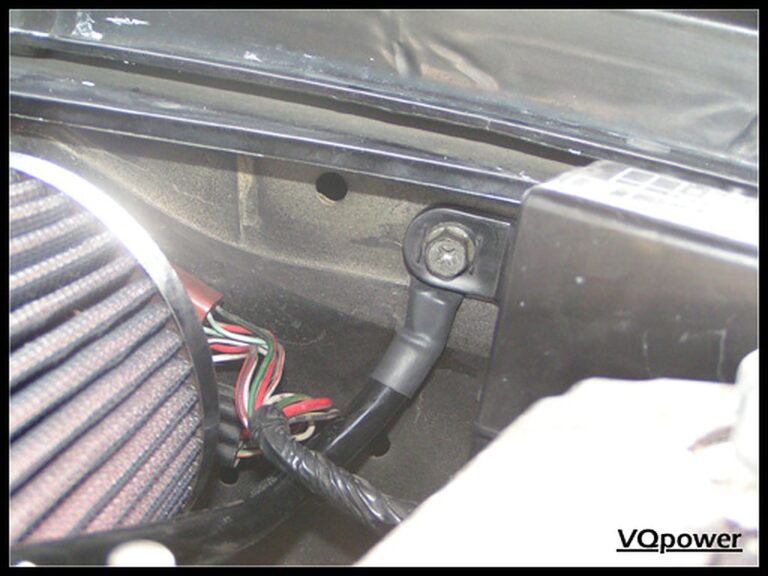
Last and certainly not least, you are going to secure the final grounding wire (14″) to the top mounting bolt located in the center of the Intake Plenum. To get to this you are going to need some finesse but it will work out perfectly in the end. Secure one end of your grounding wire to this bolt, underneath the bracket, and secure. Mount the other end of the wire just below the black canister shown in the third picture to the protruding screw on the firewall with the nut supplied.*
*Picture shows different locations from the description but are later routed how it is explained here.


Make sure all mounting points are secured properly, take the car for a spin, and enjoy. 🙂

Community Member Credit: KRRZ350 / MrCurst
Step 1: Remove #1 coil/plug and position #1 cylinder at TDC on the compression stroke.
Step 2: Remove upper half of engine mount and anything else that might get in the way of step 3
Step 3: Remove tensioner inspection cover.
Step3: Compress and lock the tensioner, then remove it.
Step 4: Using a 19mm socket, rotate the crankshaft counterclockwise until you hear the chain skip a tooth.
Step 5: Re-install everything and verify correct ignition timing and vacuum reading
This only applies if you skipped timing upon initial cranking, and only if it skipped on the crank sprocket, but I believe that’s where it skips every time.


Community Member Credit: mpvibes
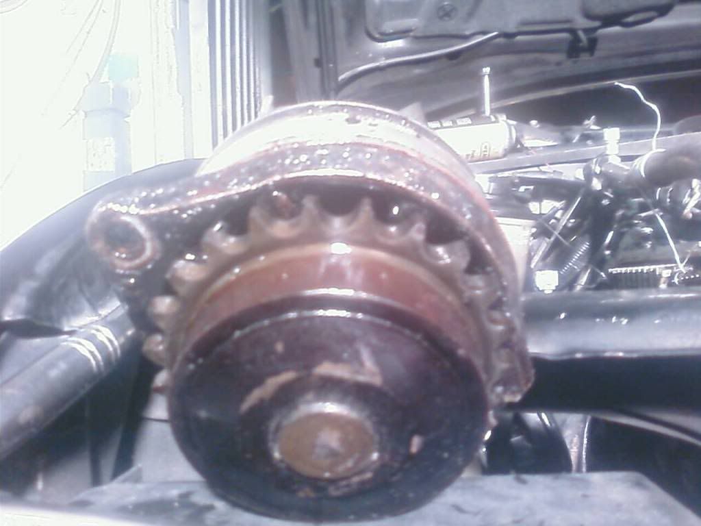
So, I decided to go ahead and do the dreaded water pump replacement job on my EDIT: 263,000 mile 4th gen. What a PITA! I had to do it the long way because #1 I had a leak on my timing chain cover and # 2 I wanted to make sure my timing was accurate and my car didn’t jump timing, bend any valves, etc. Well, since it was my first time ever doing this job, it took me 2 days and I did learn a lot. Man, my oil pan and all my timing chain components were covered in oil sludge, it was ugly I had to do a lot of cleaning, using gasoline! Well, here are some pics that I wanted to share with you all. Sorry for some of the crappy pics…
UPDATE: When cleaning and putting on the lower oil pan just get a NEW Felpro oil pan gasket and follow the tightening sequence! Do not put RTV silicone on there. I had a leak and had to get a Felpro gasket.
New Nissan Water Pump

Oil sludge all over timing components


Broke the old water pump while taking it out
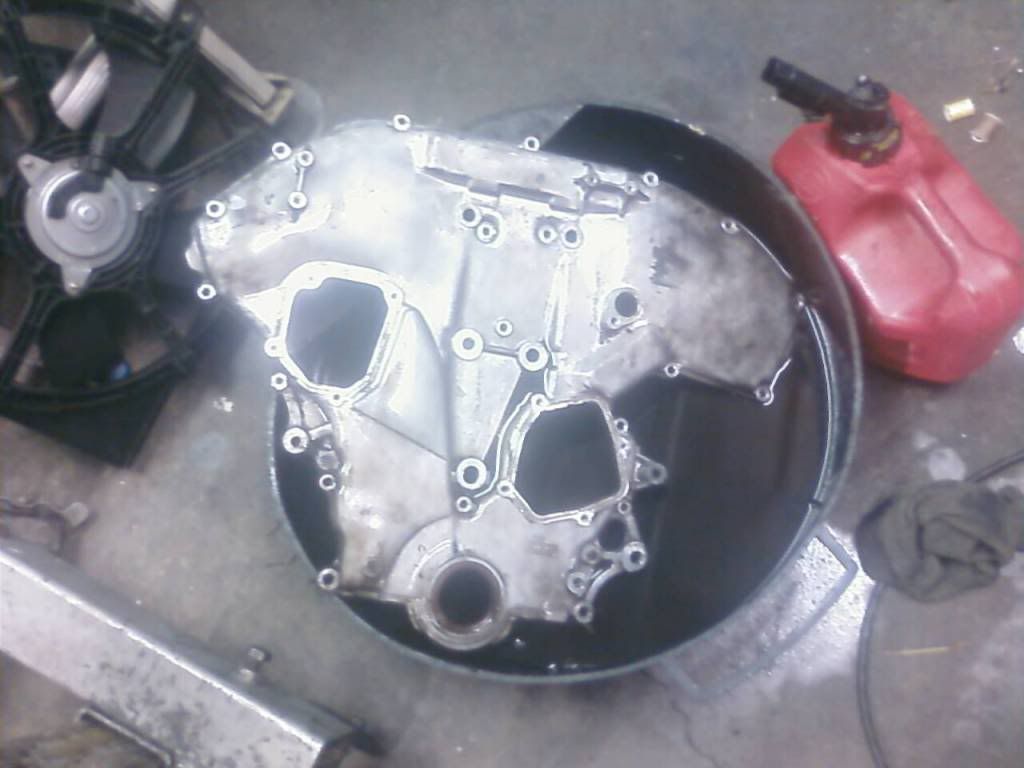


Cleaned and looking good!


Old Thermostat and New Thermostat side by side