![]()


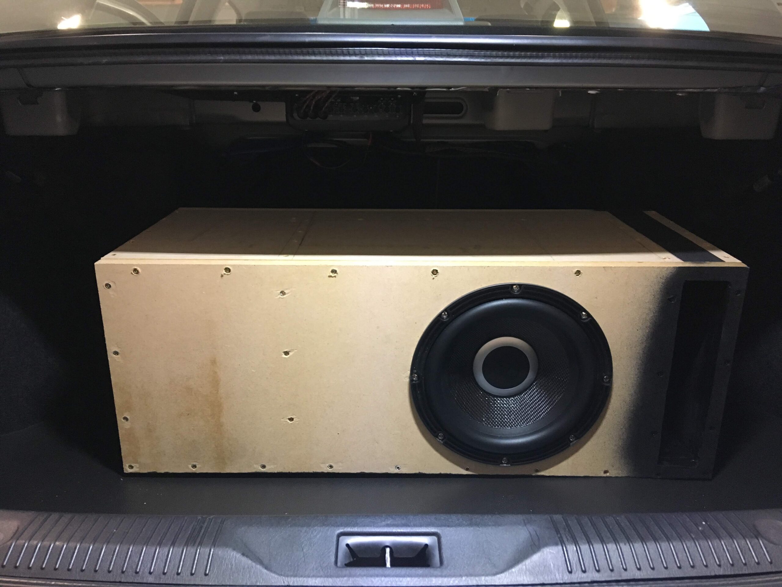
 Subwoofer Enclosure on Infiniti FX35 2003-2008")
Community Member Credit: elusive
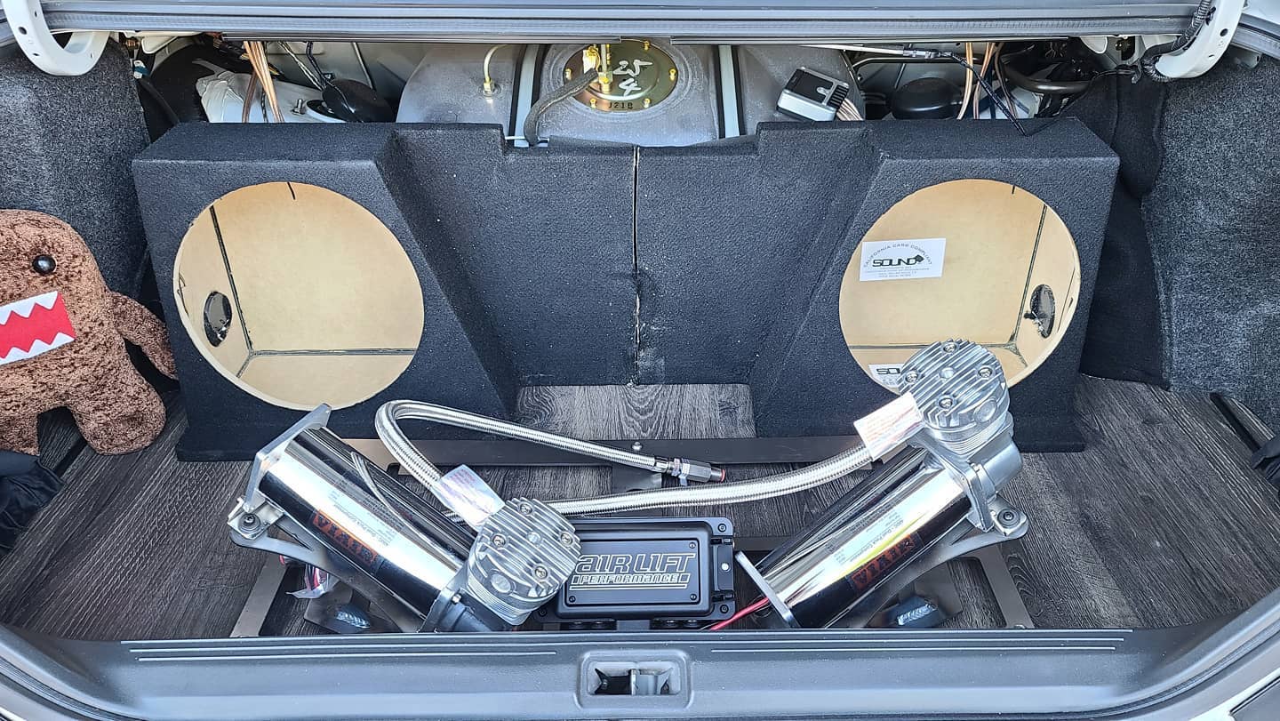
This came about because I had to get rid of my lunker of a sub (12″ ported) and reclaim half of my trunk space. I didn’t want to spend $400 on Wicked’s box and wanted to learn to lay fiberglass. I am mounting an Alpine Type R 10″.
Difficulty: Moderate
Time: For me, it took about a week since I only worked on it here and there in between work
Cost: I spent a little over $100 on materials
Required Materials:
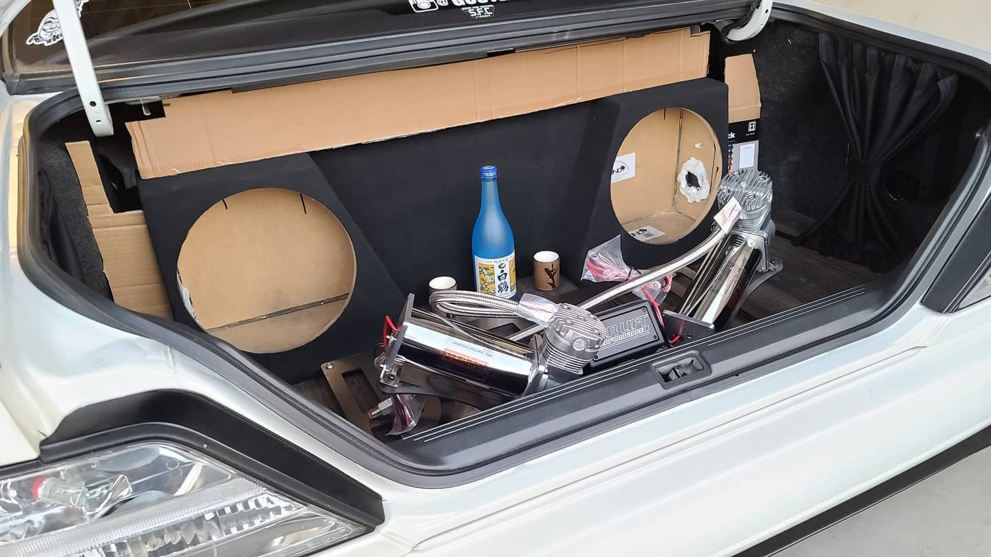
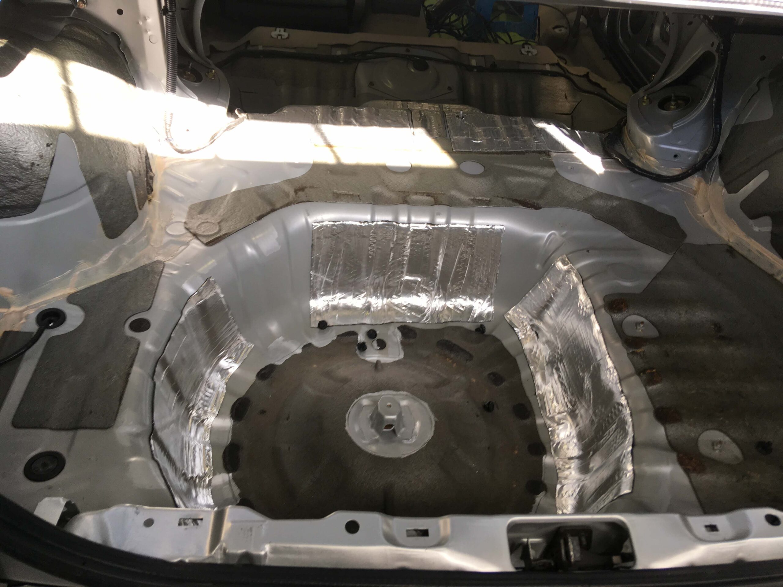
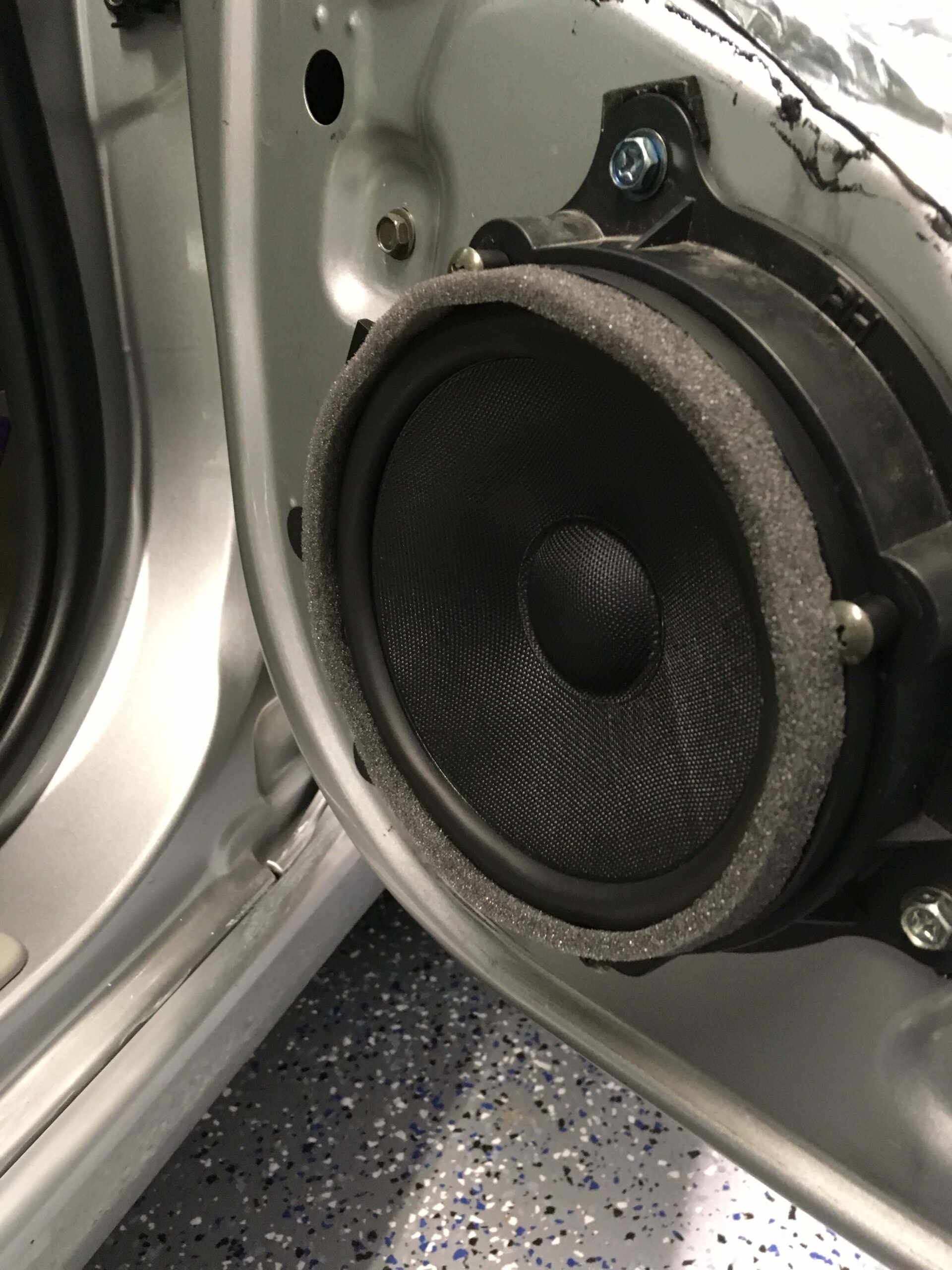
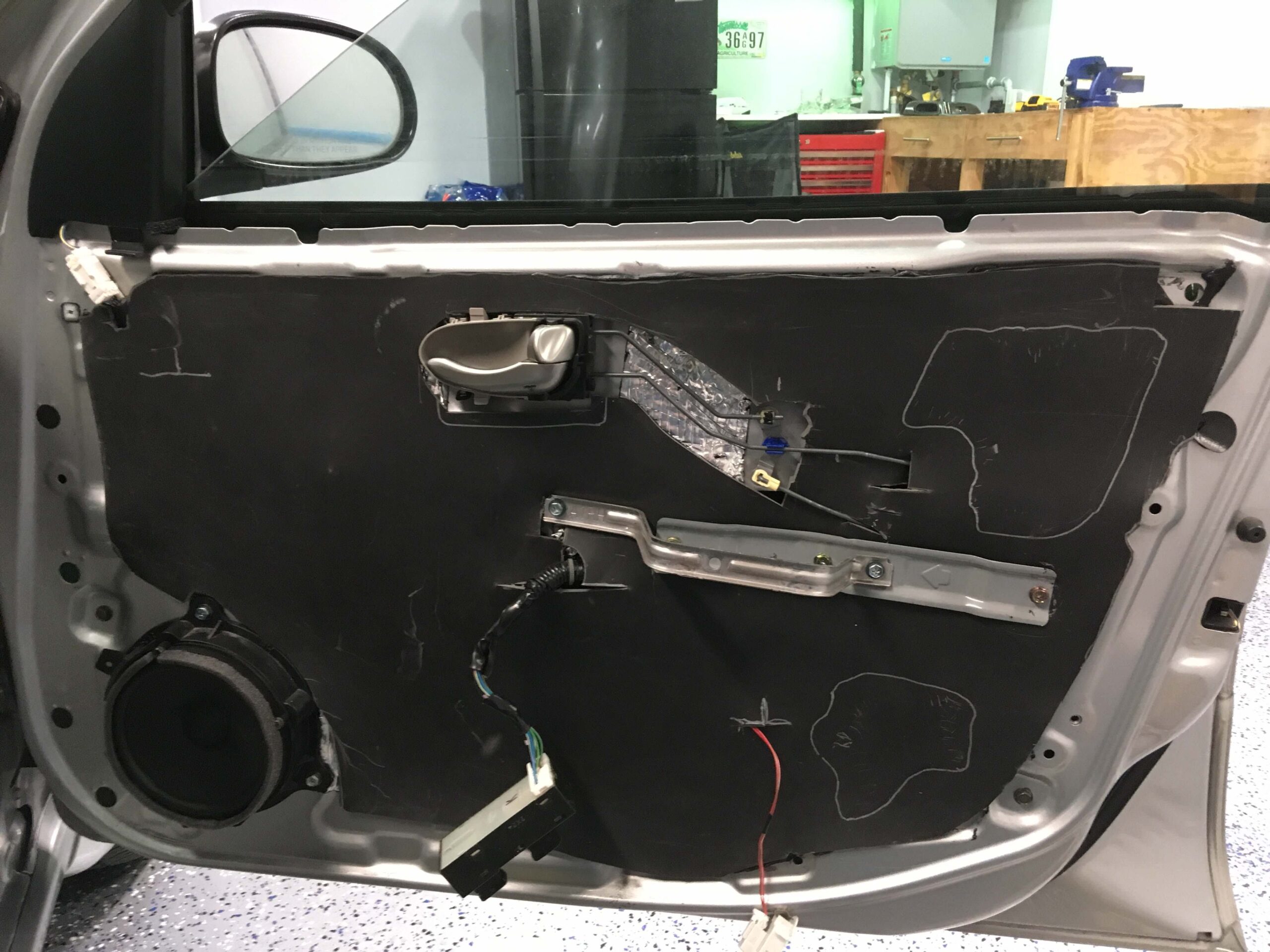
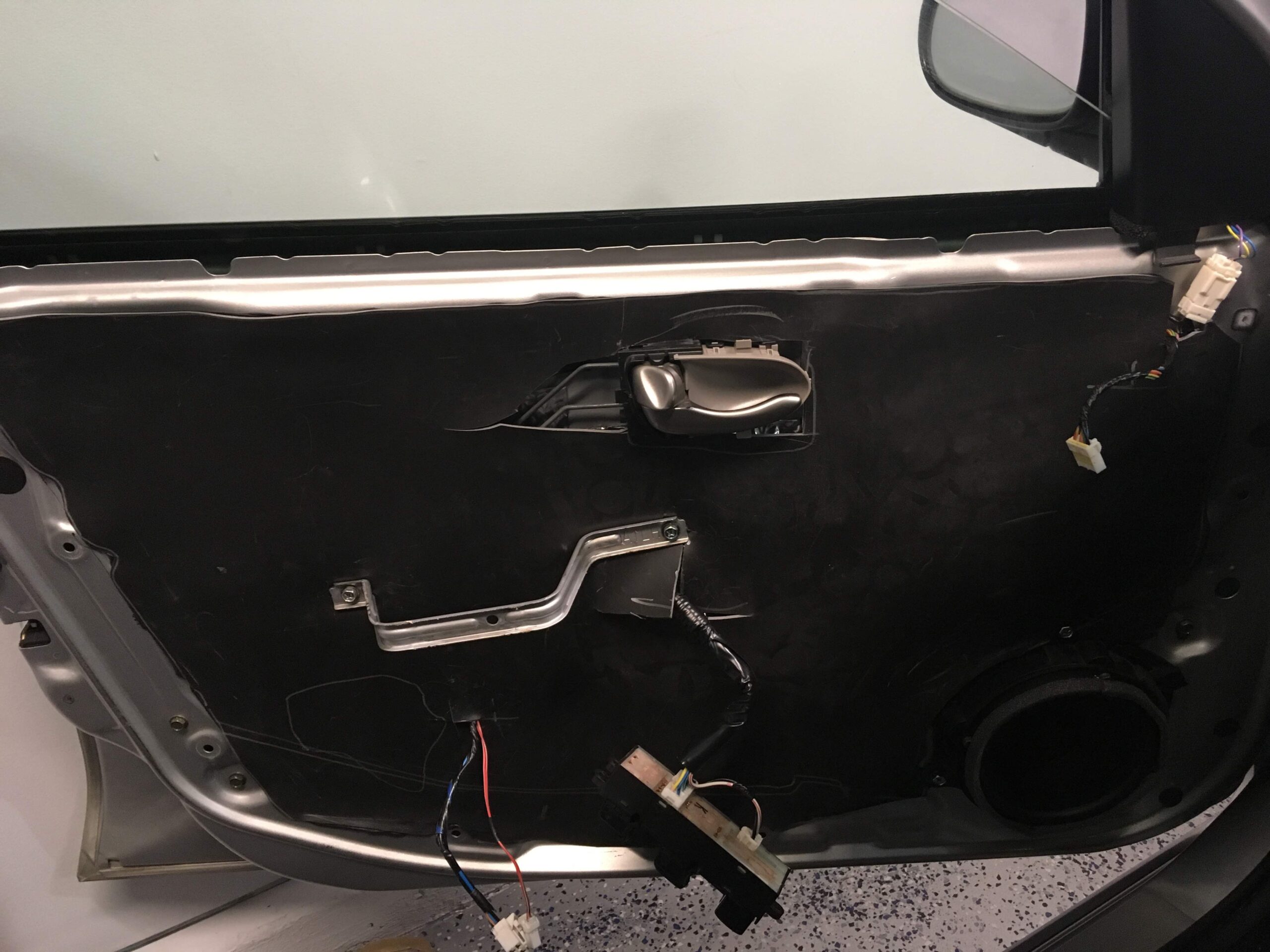
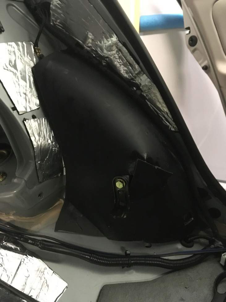
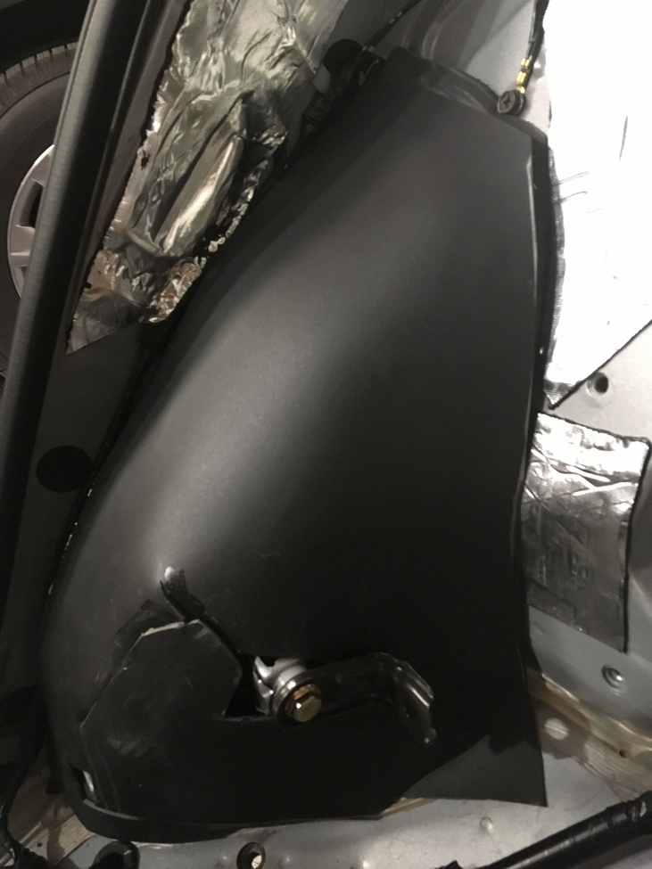
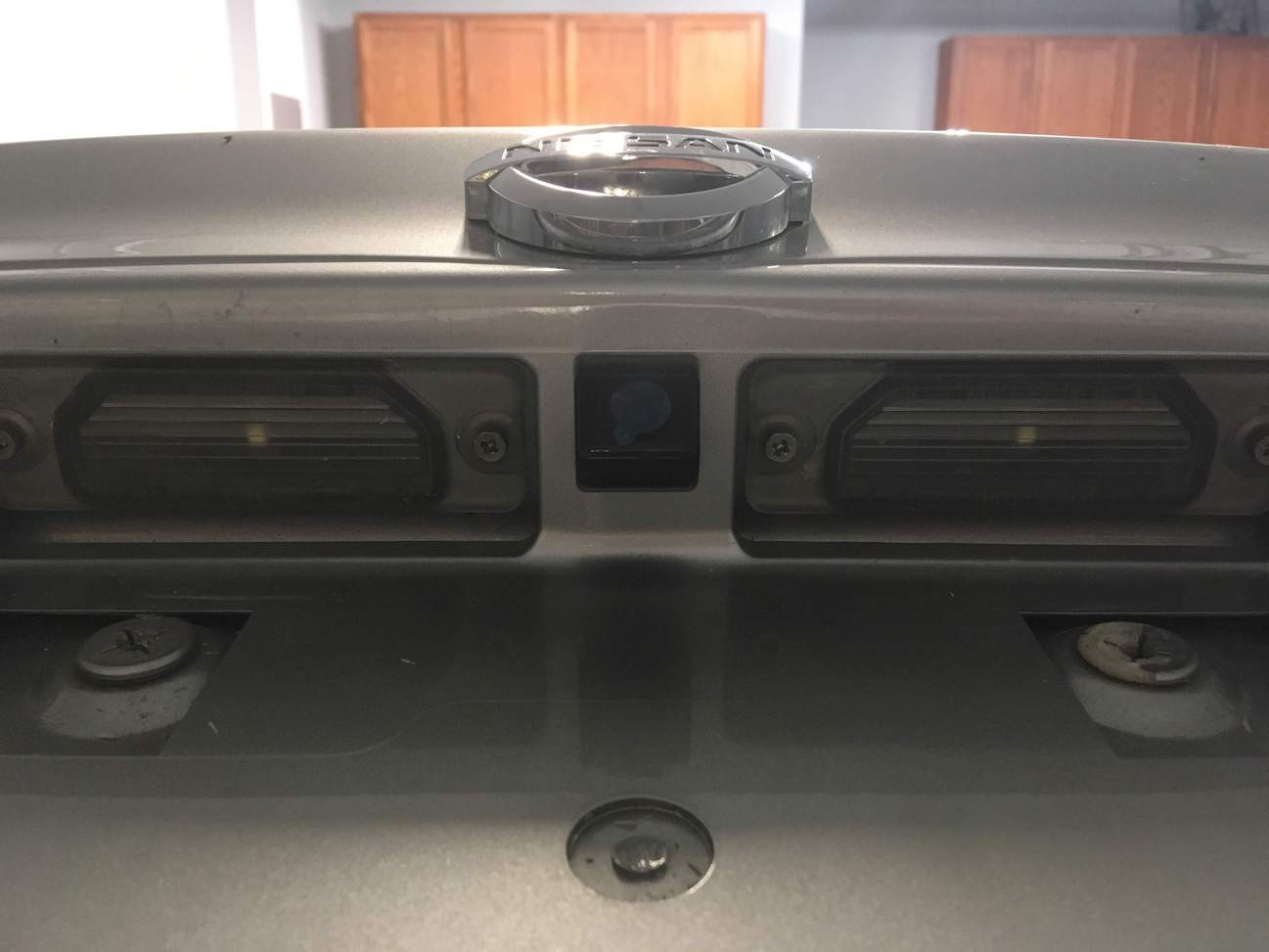
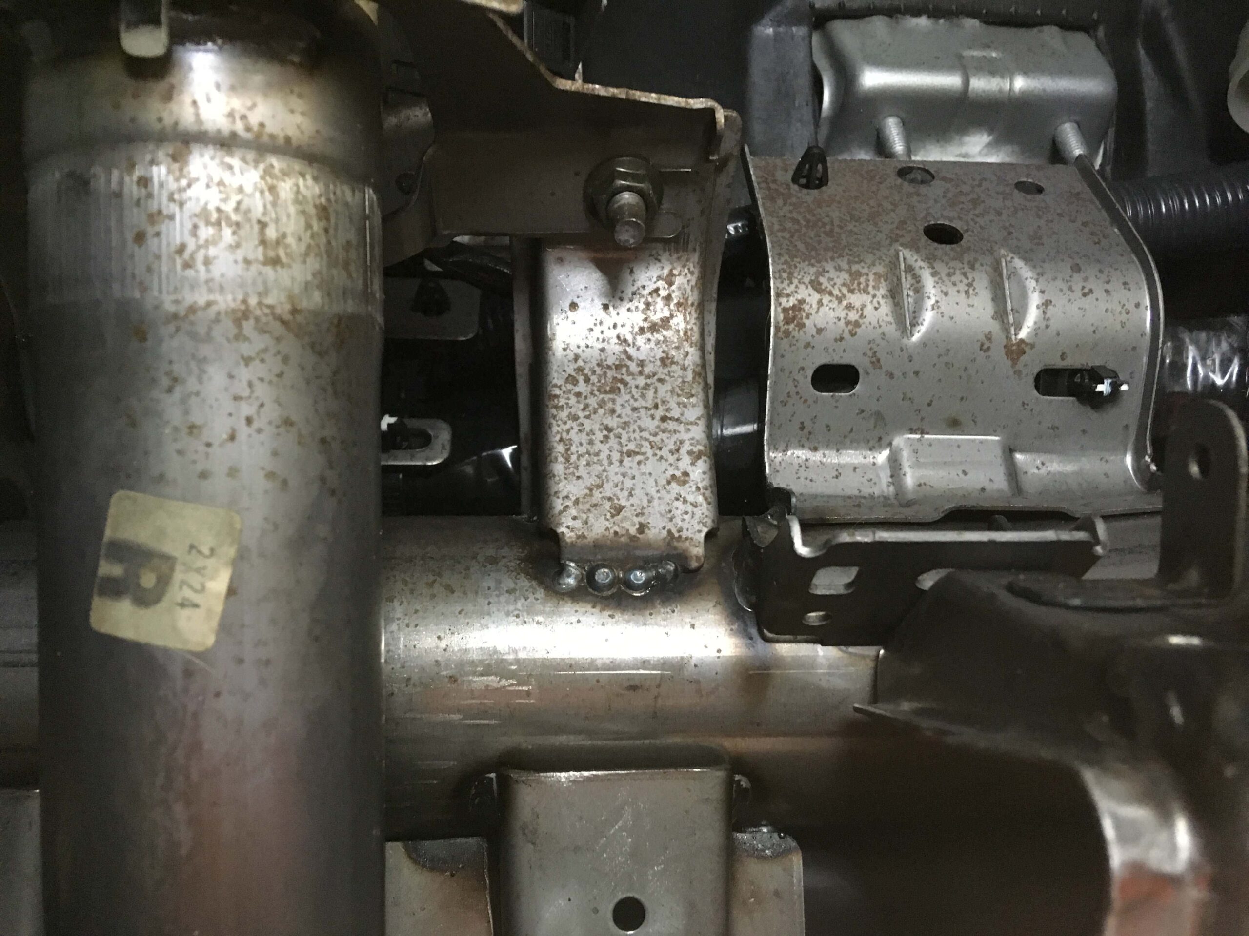
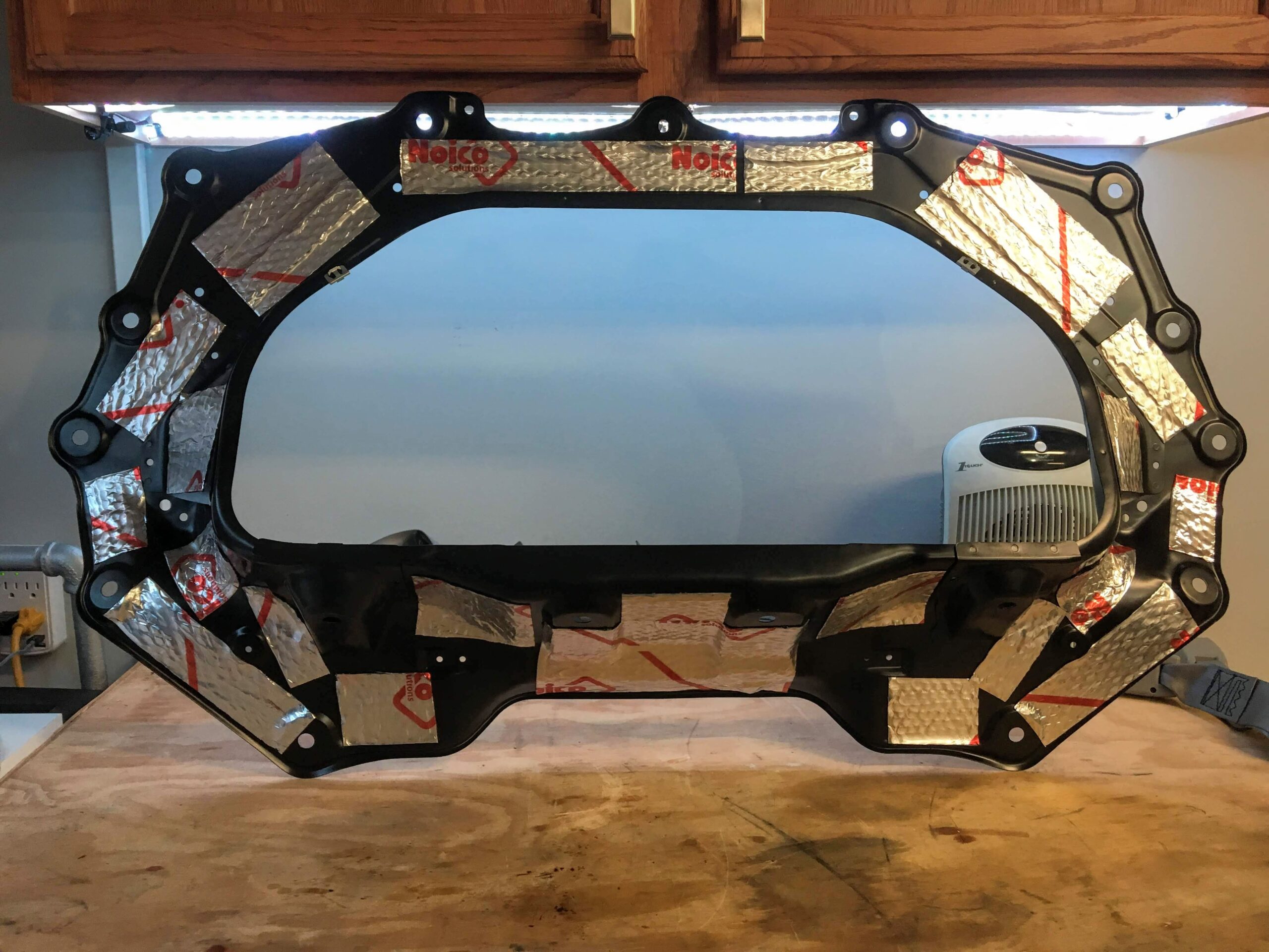
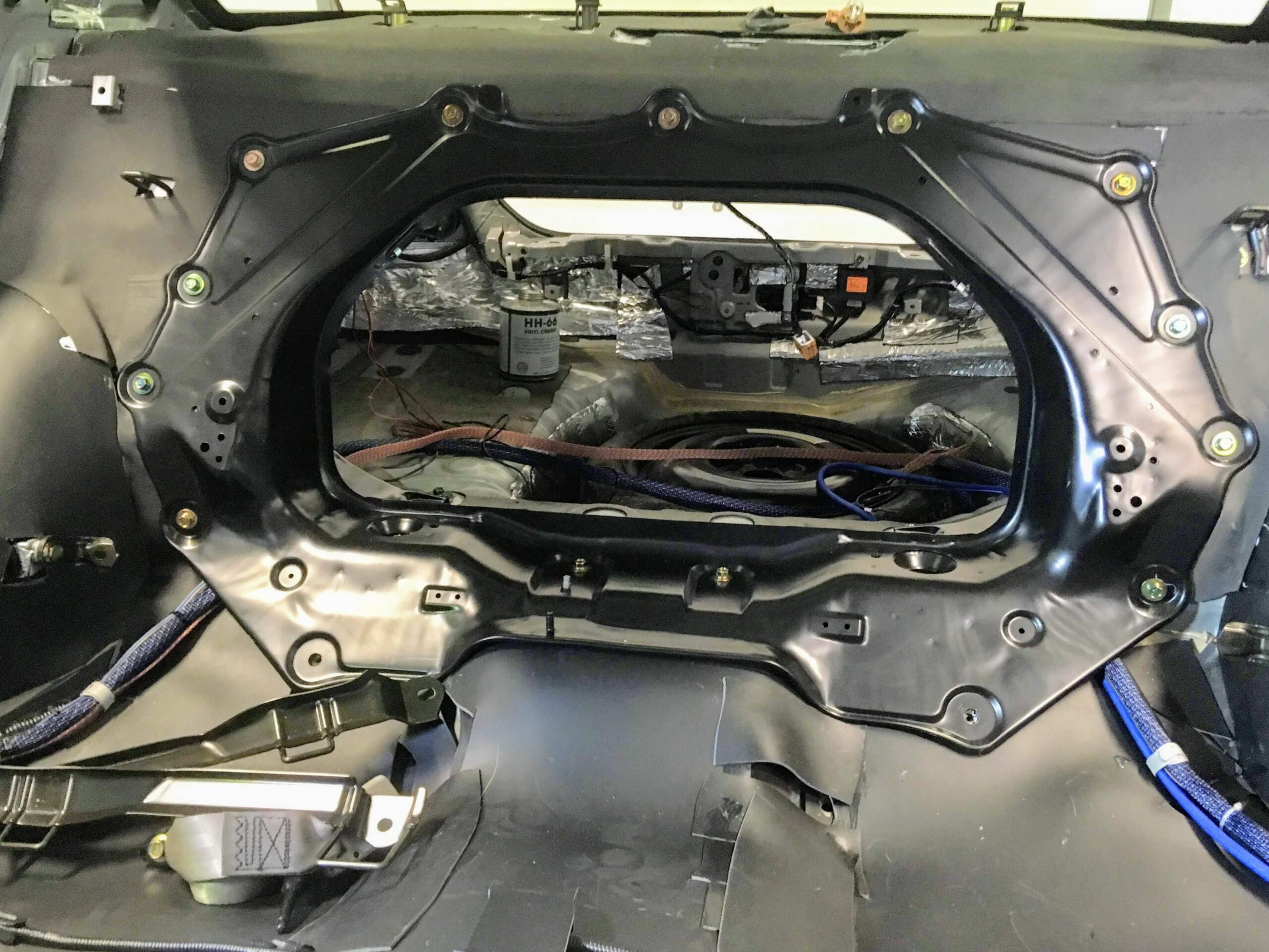
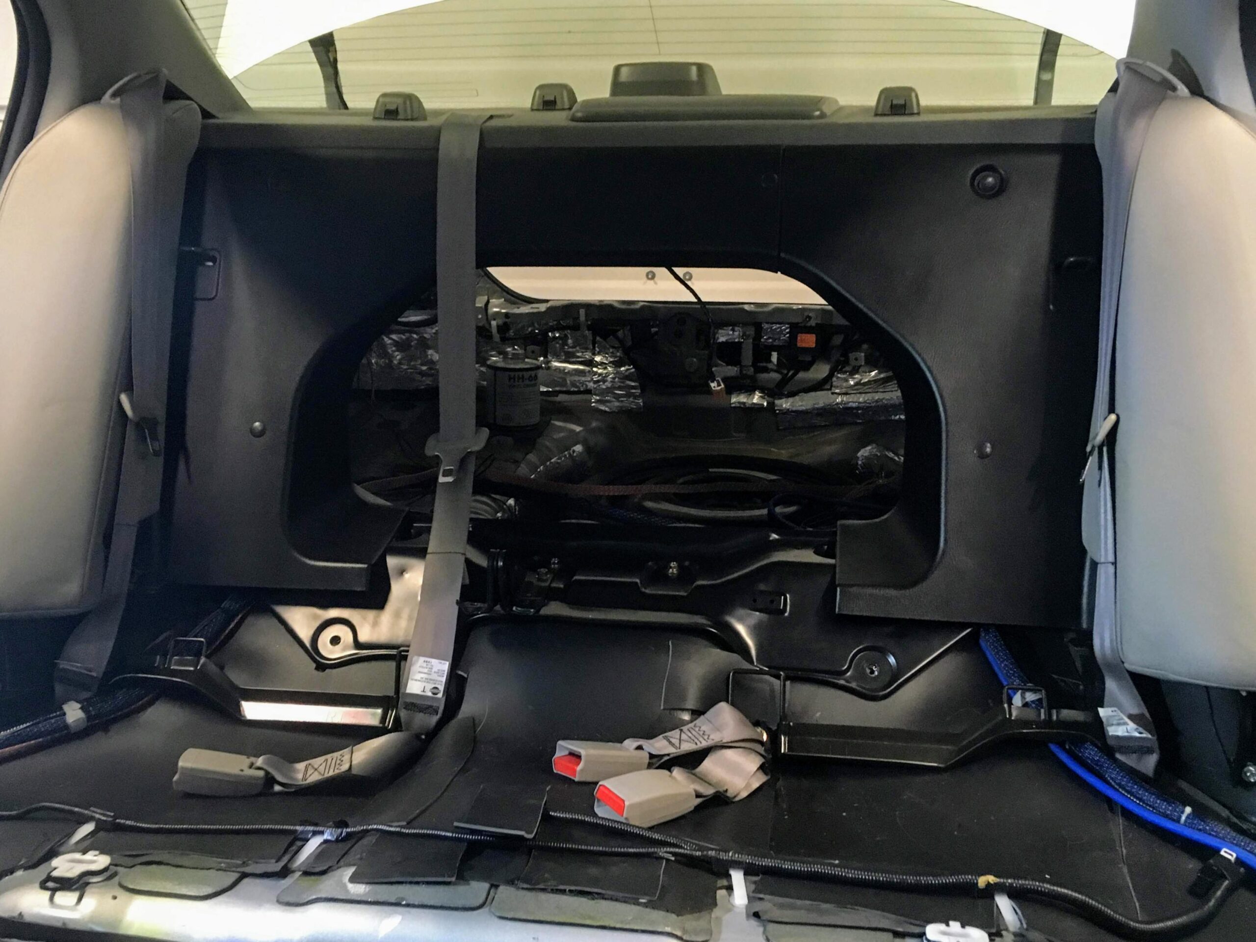
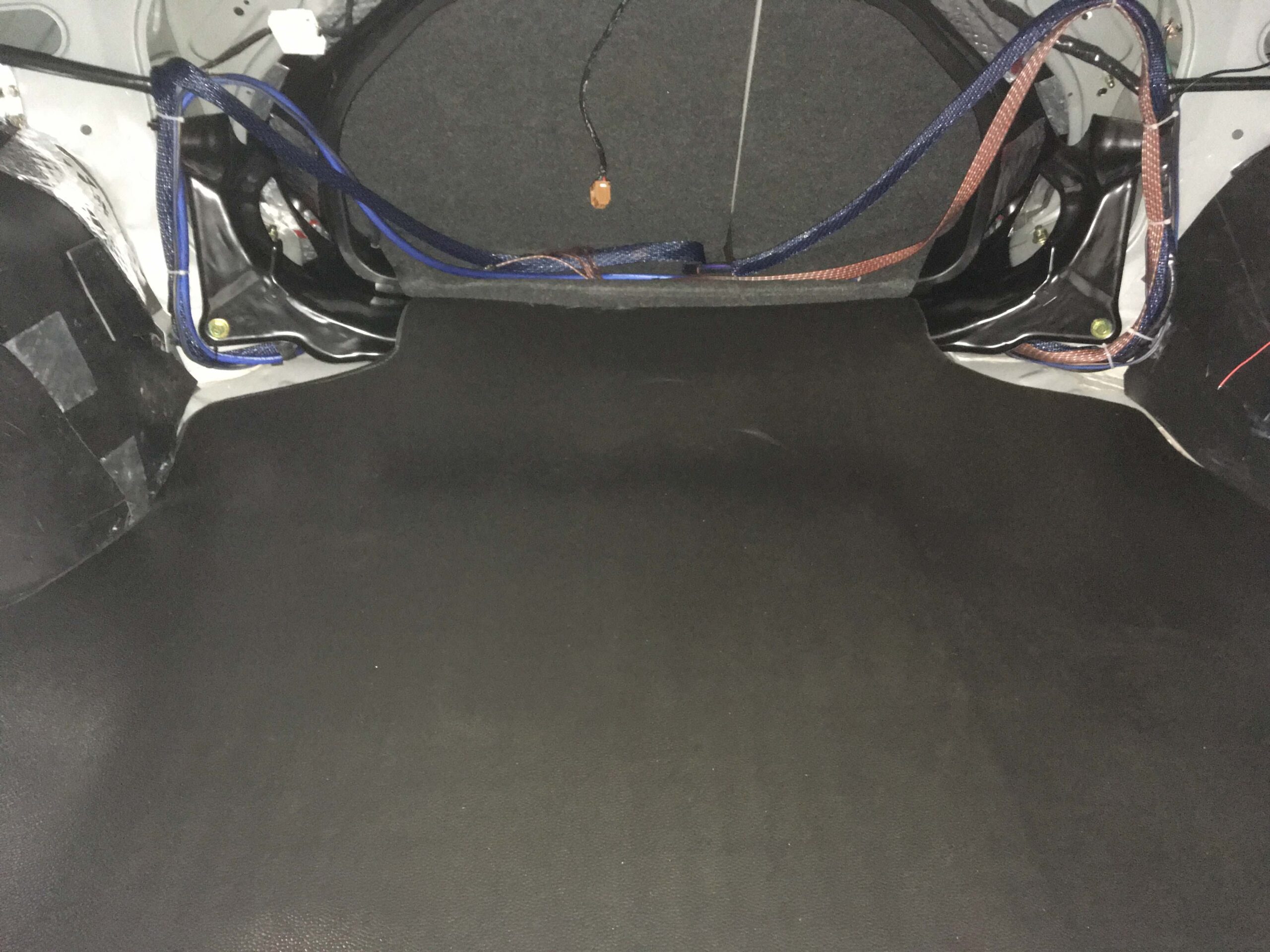
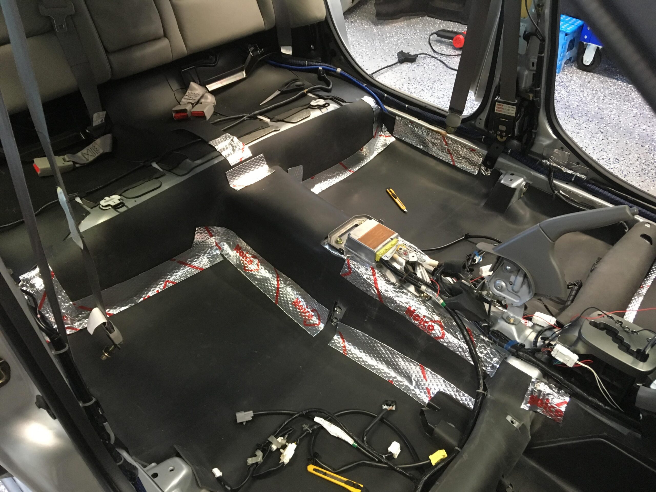
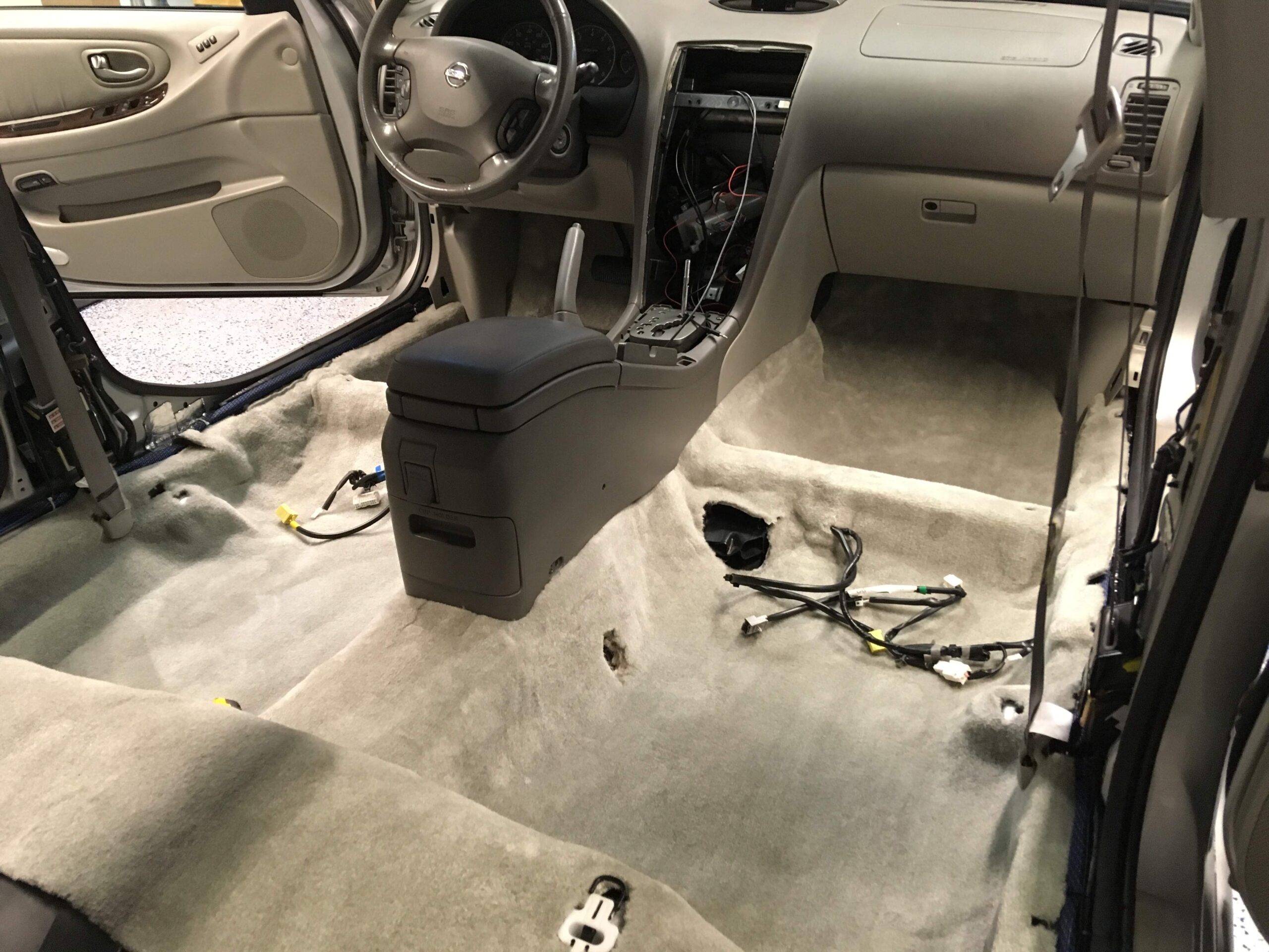
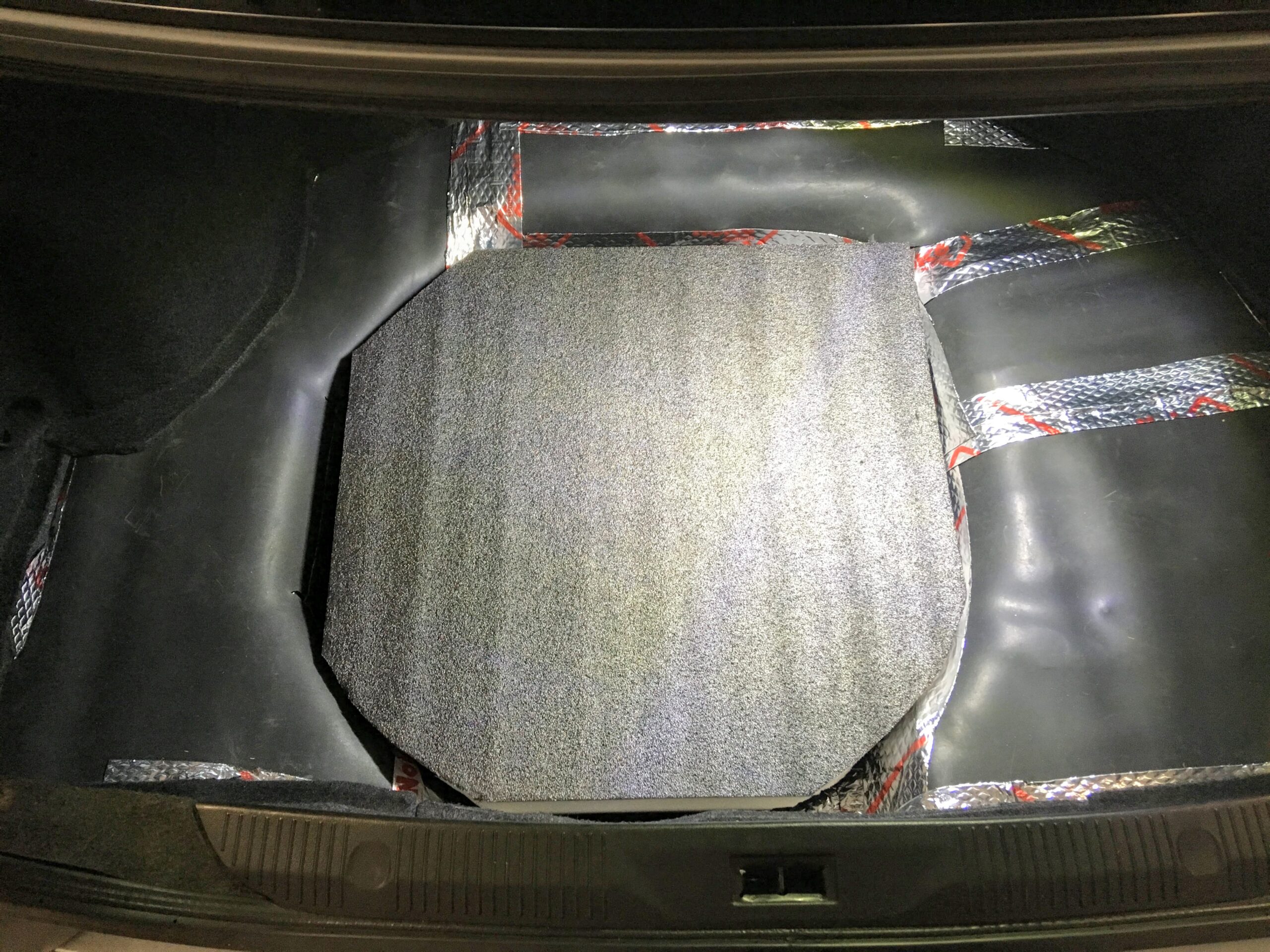
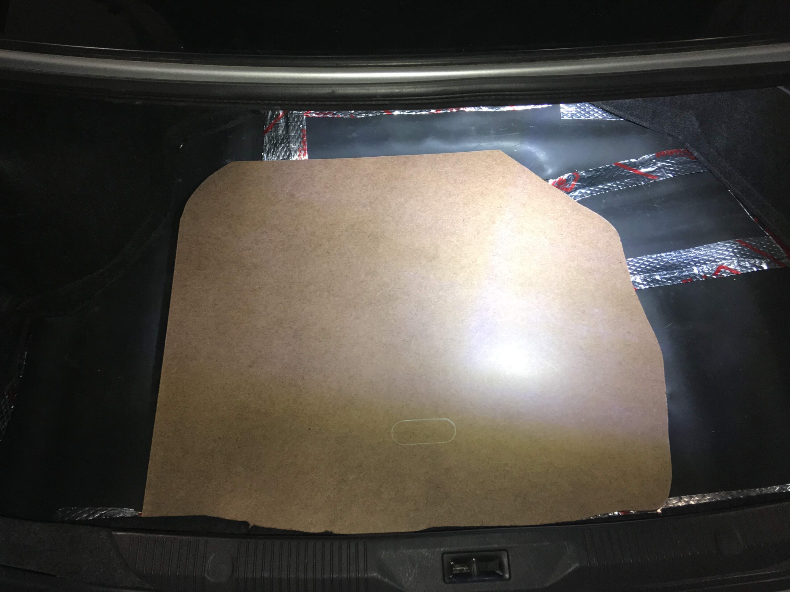
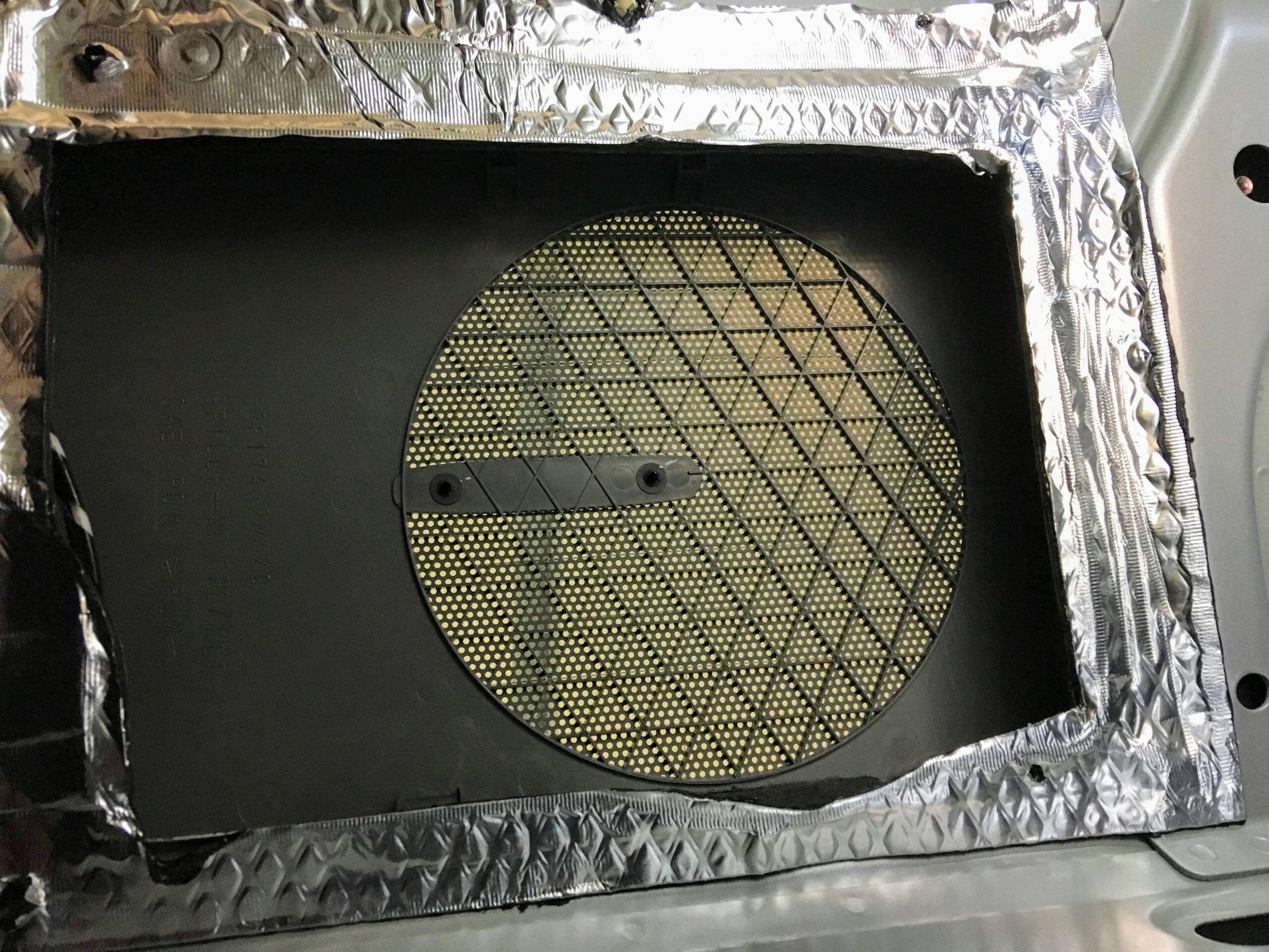
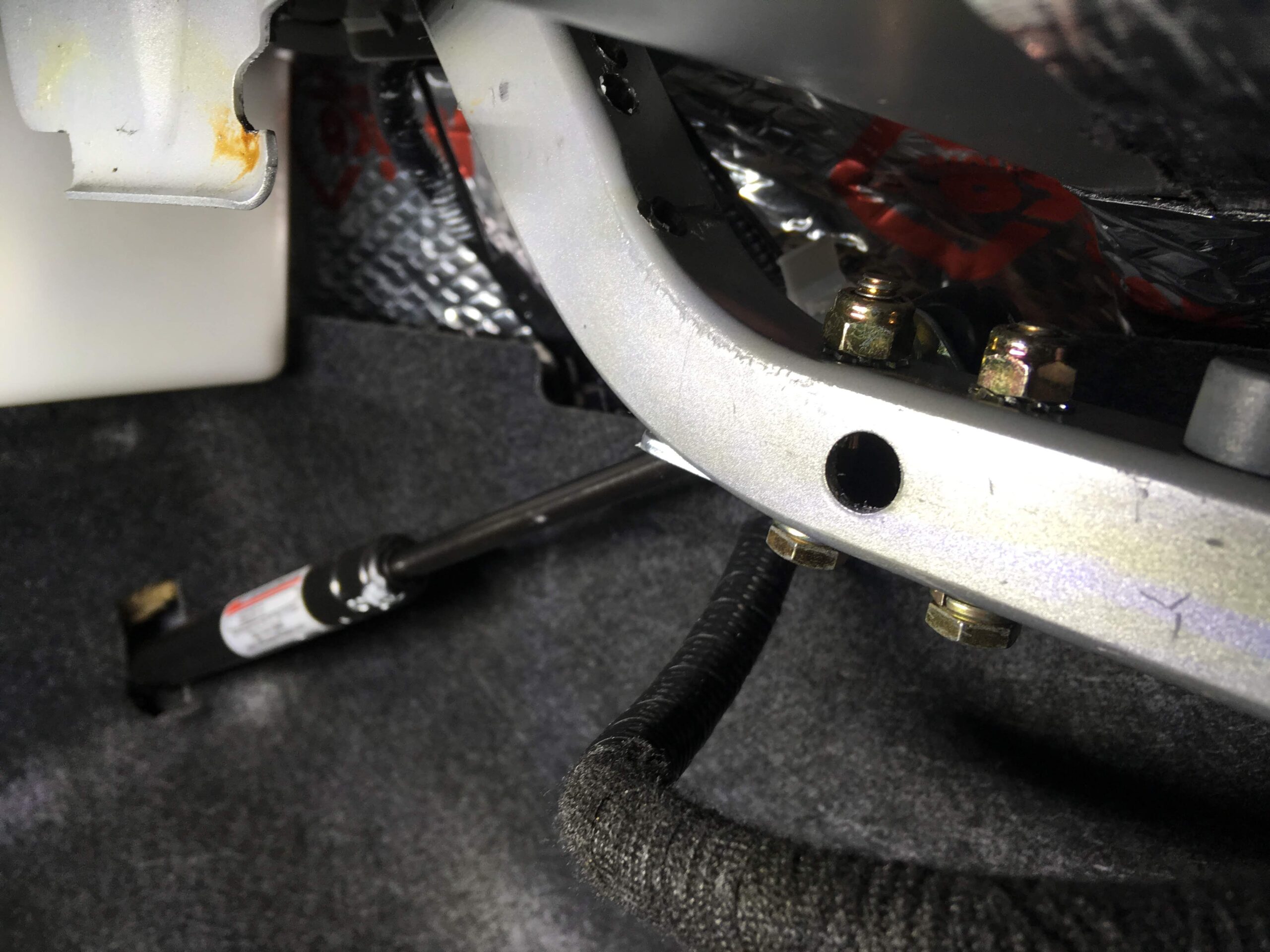
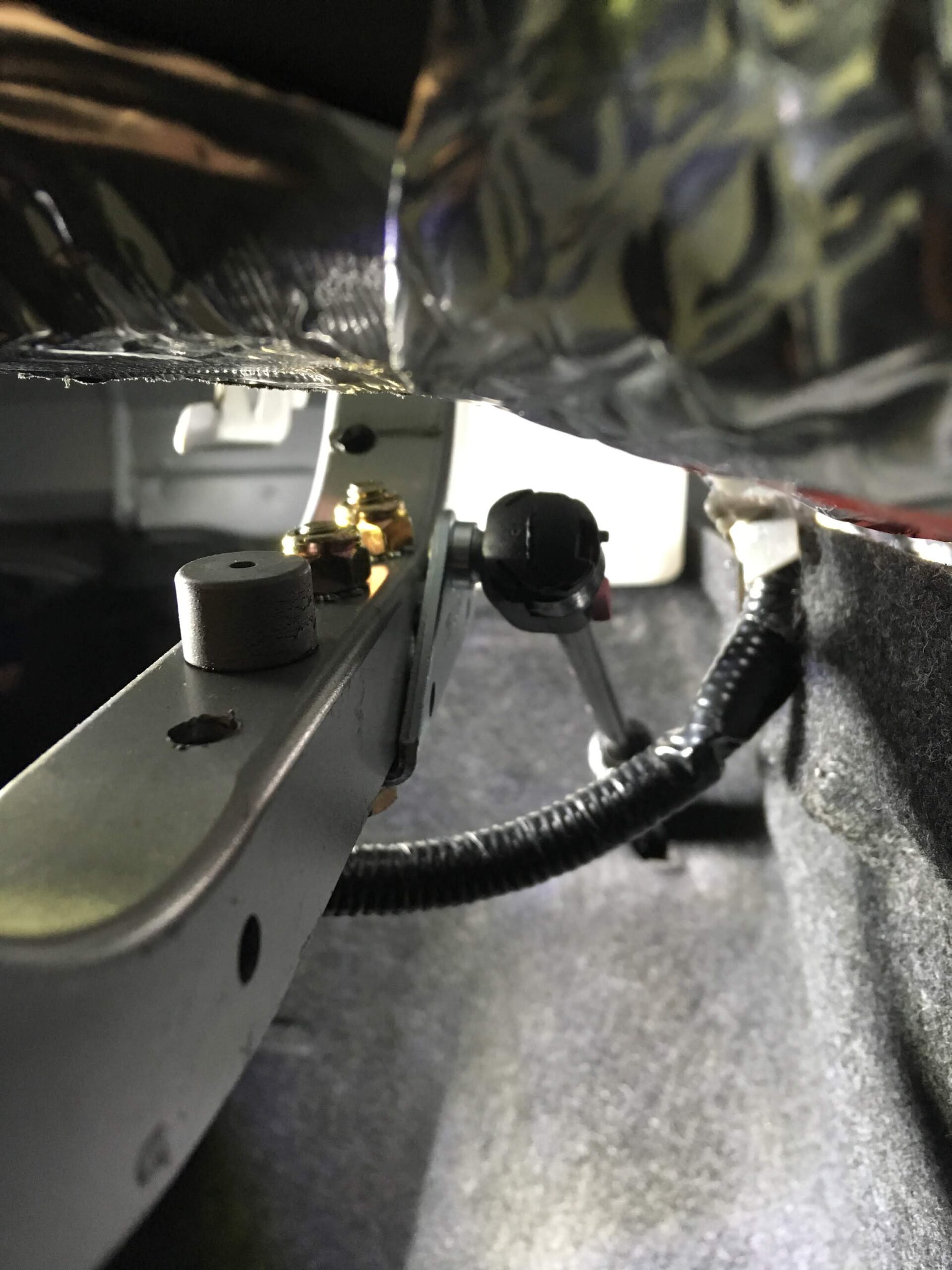
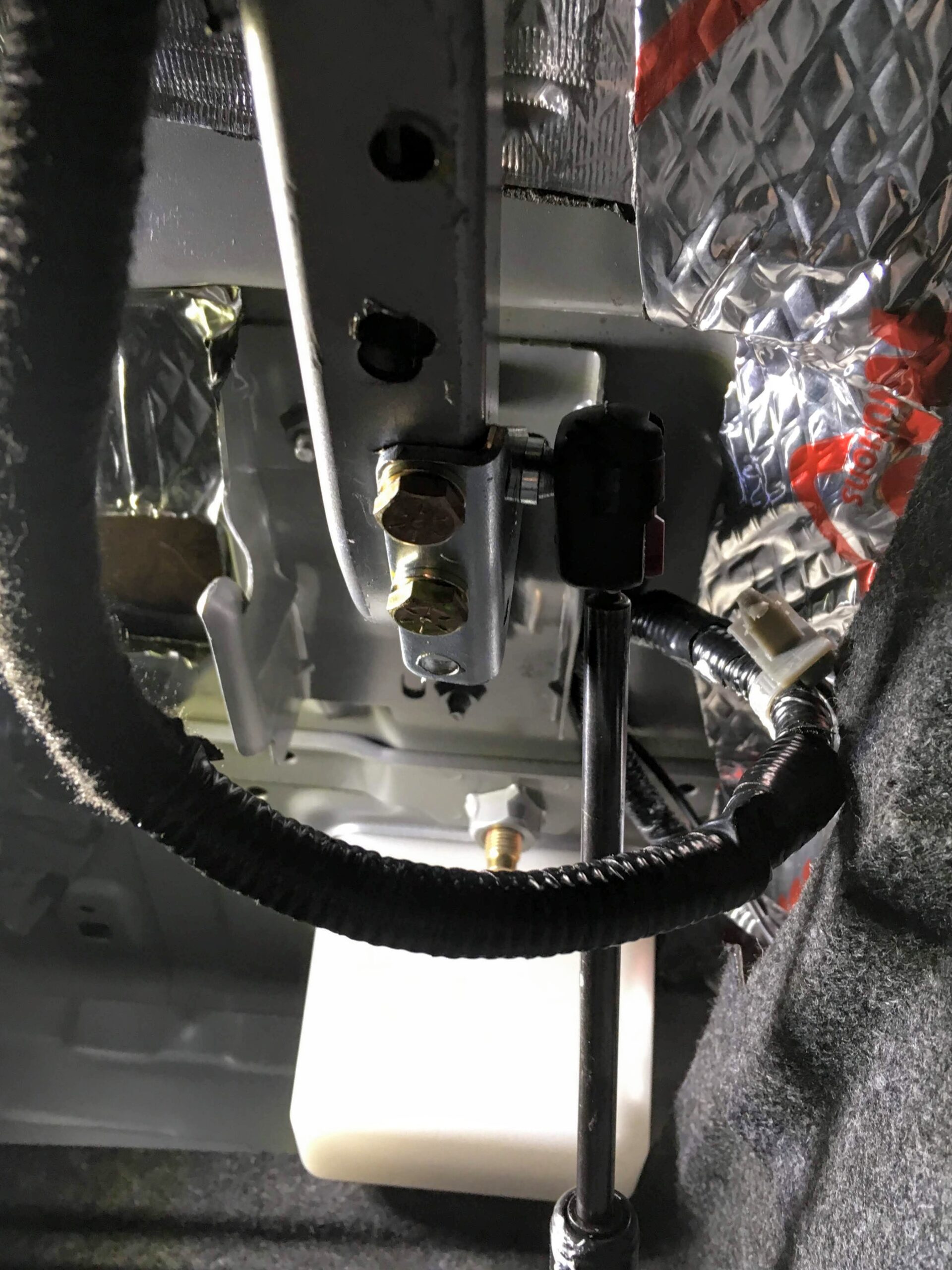
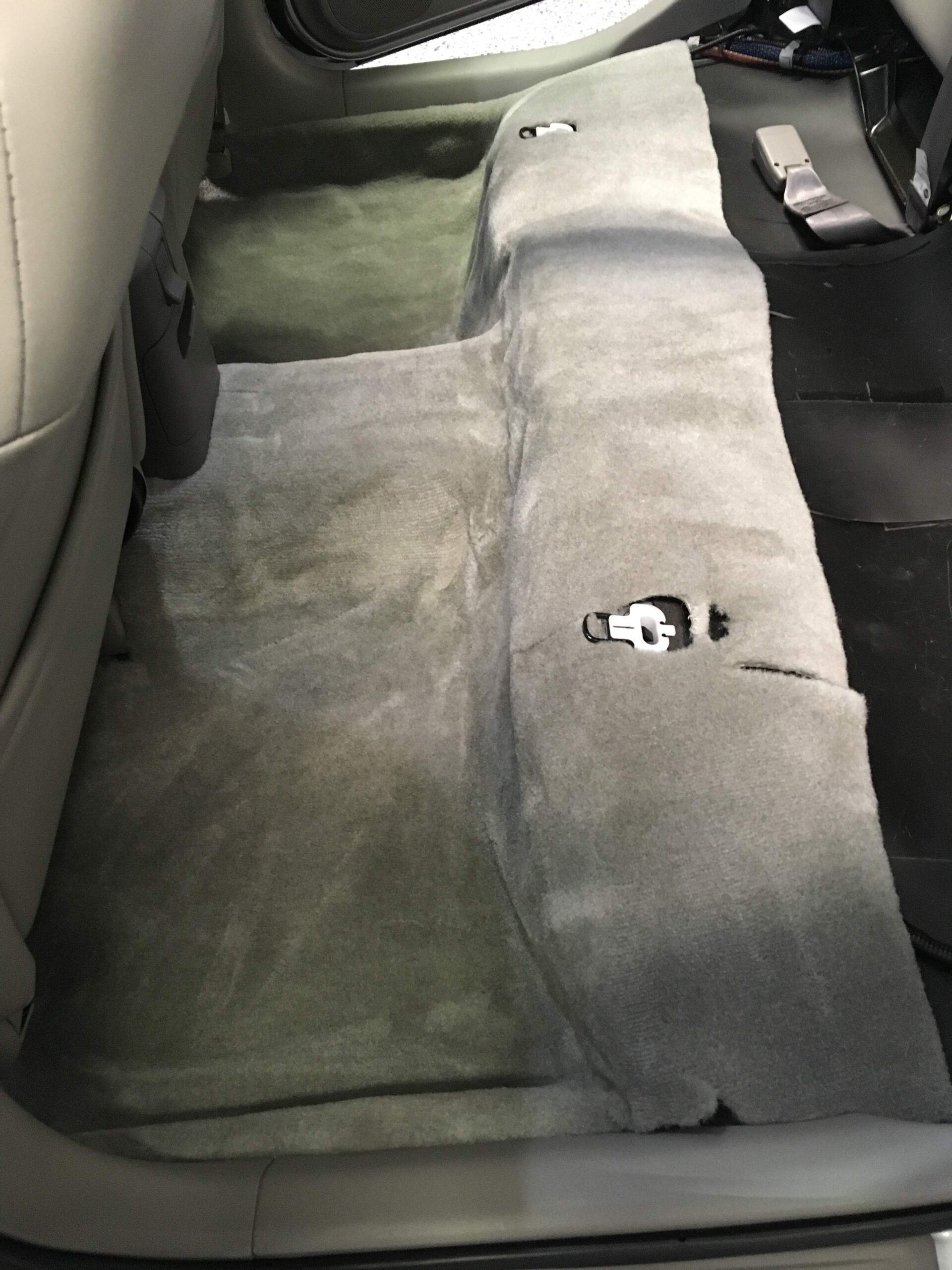
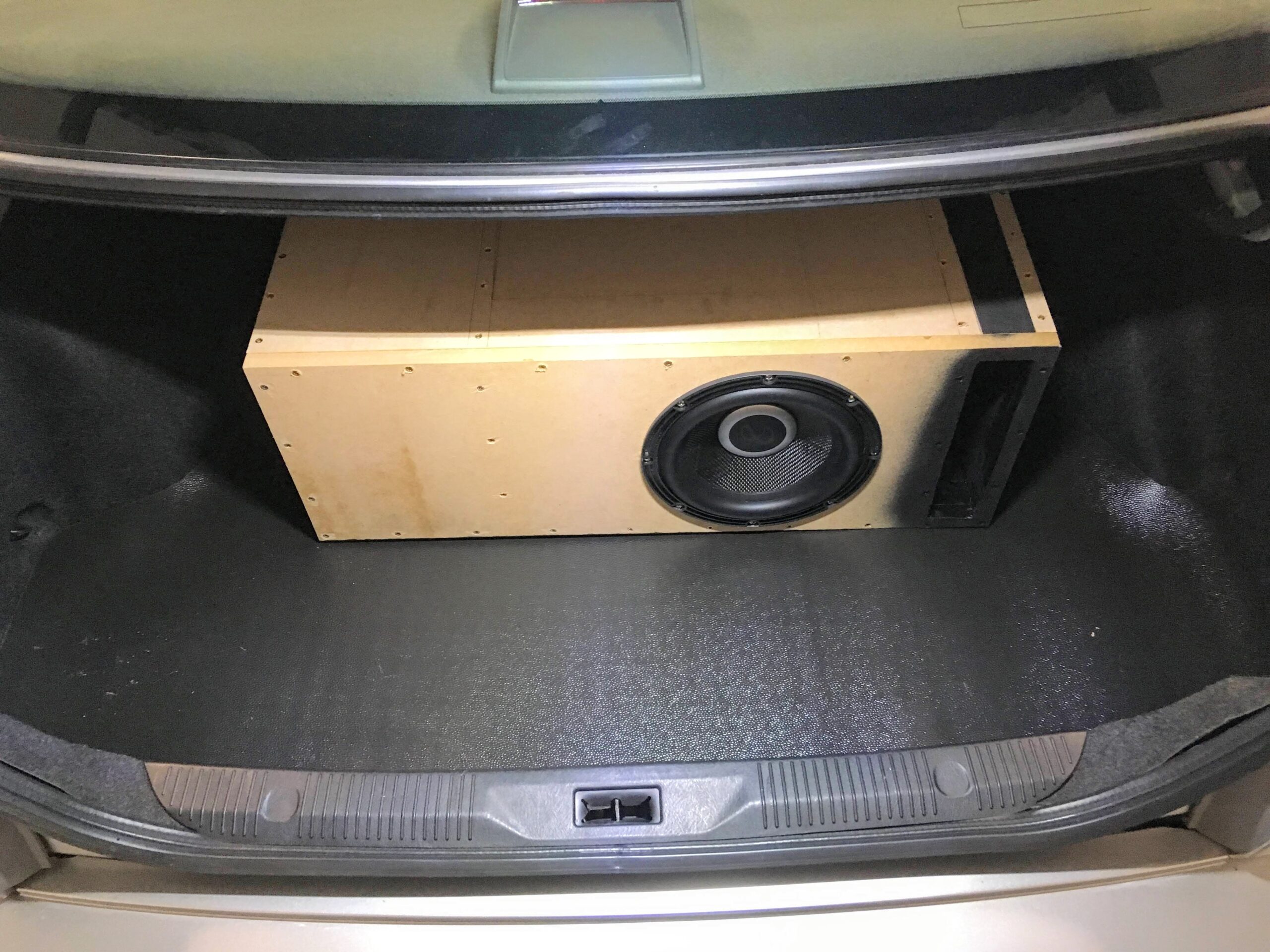
1) Wse masking tape to generously mask off the area you want to set the sub box into (commonly the nook near the trunk door). Some people remove the compartment below (see WickedCAS box) but I didn’t want to cut my trunk mat so I just did it in the corner.
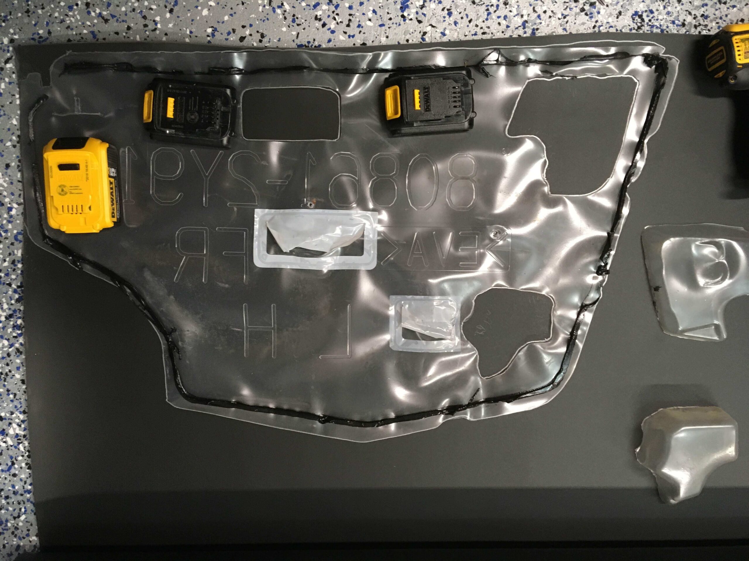
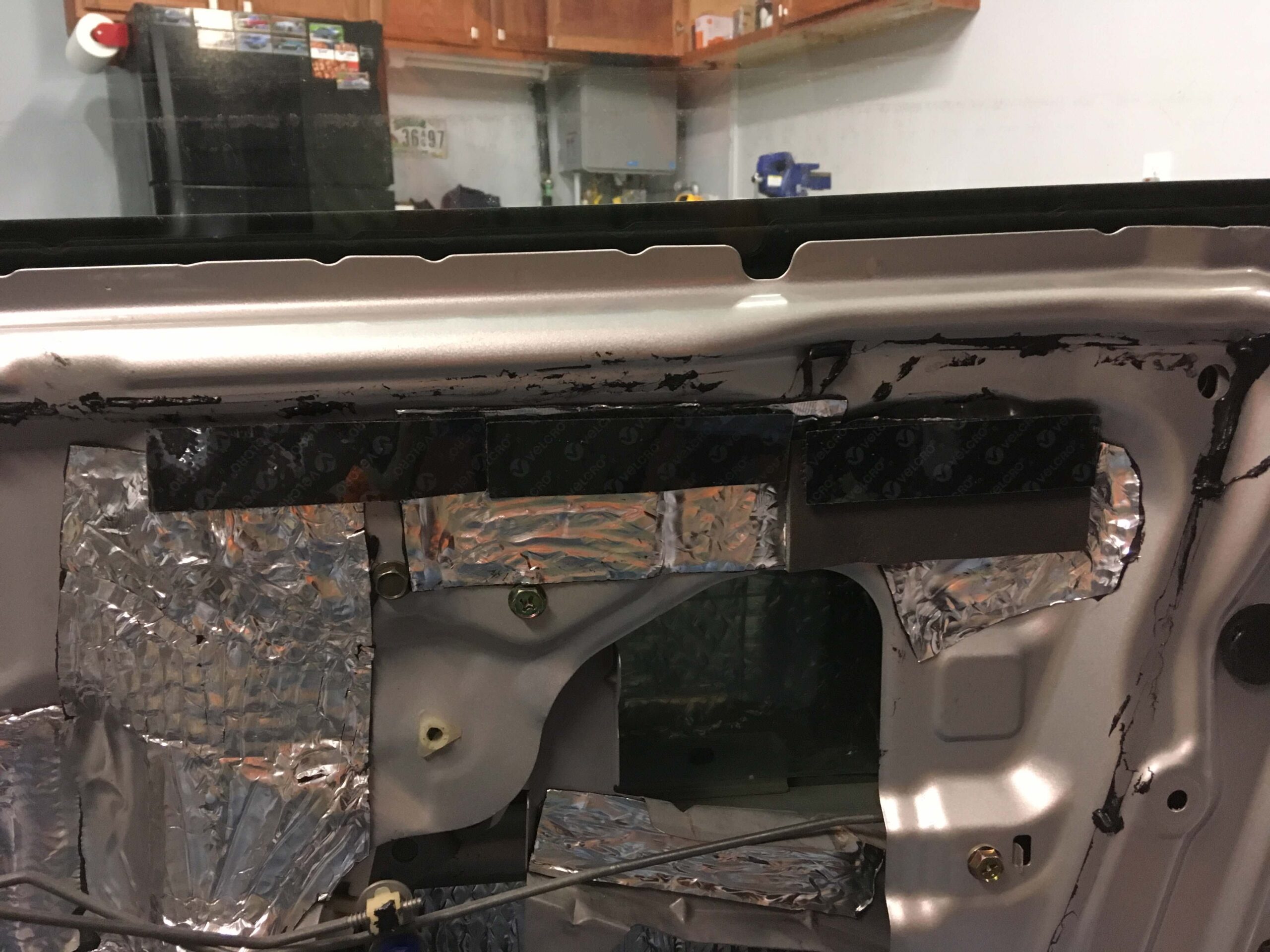
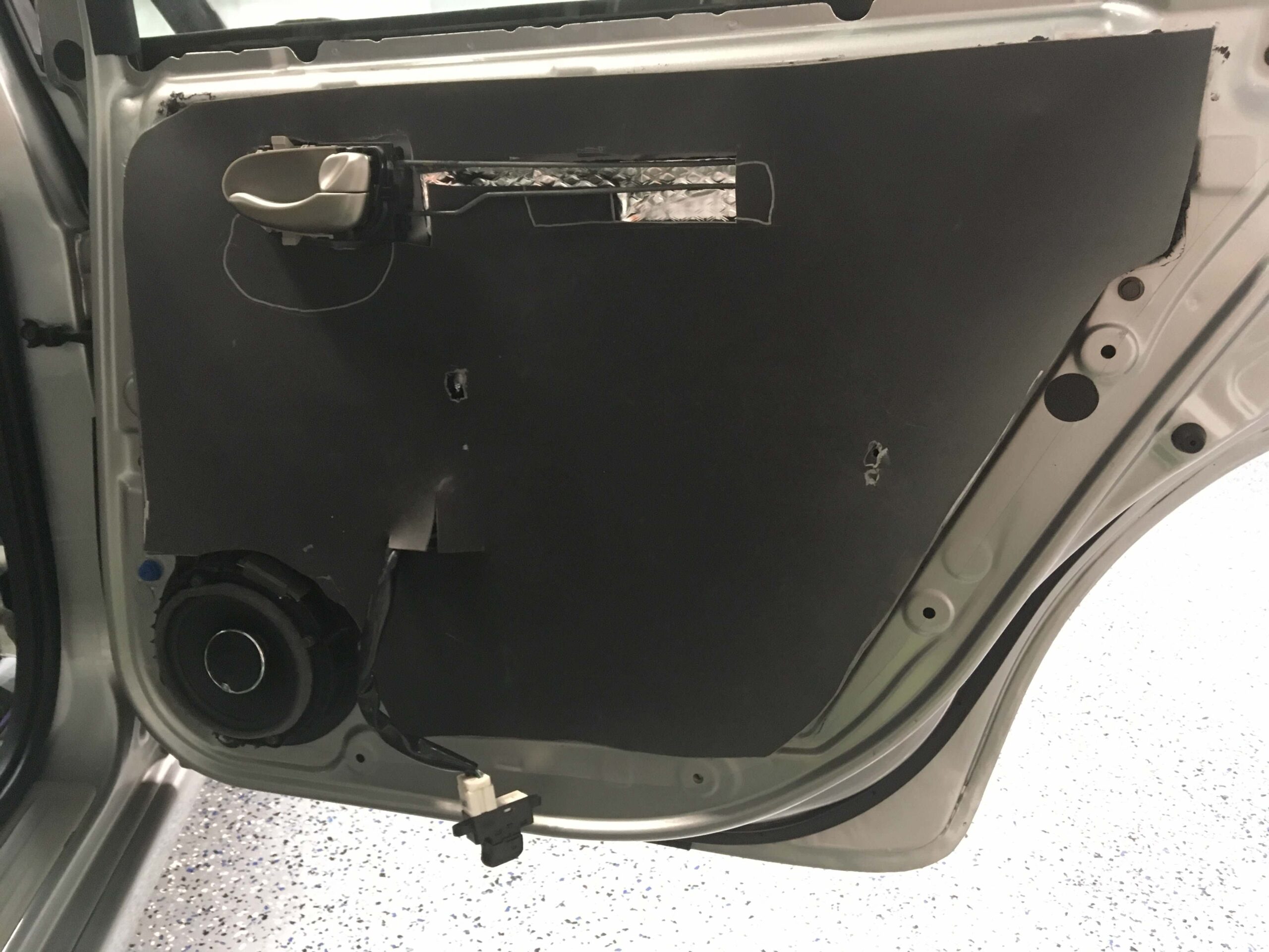
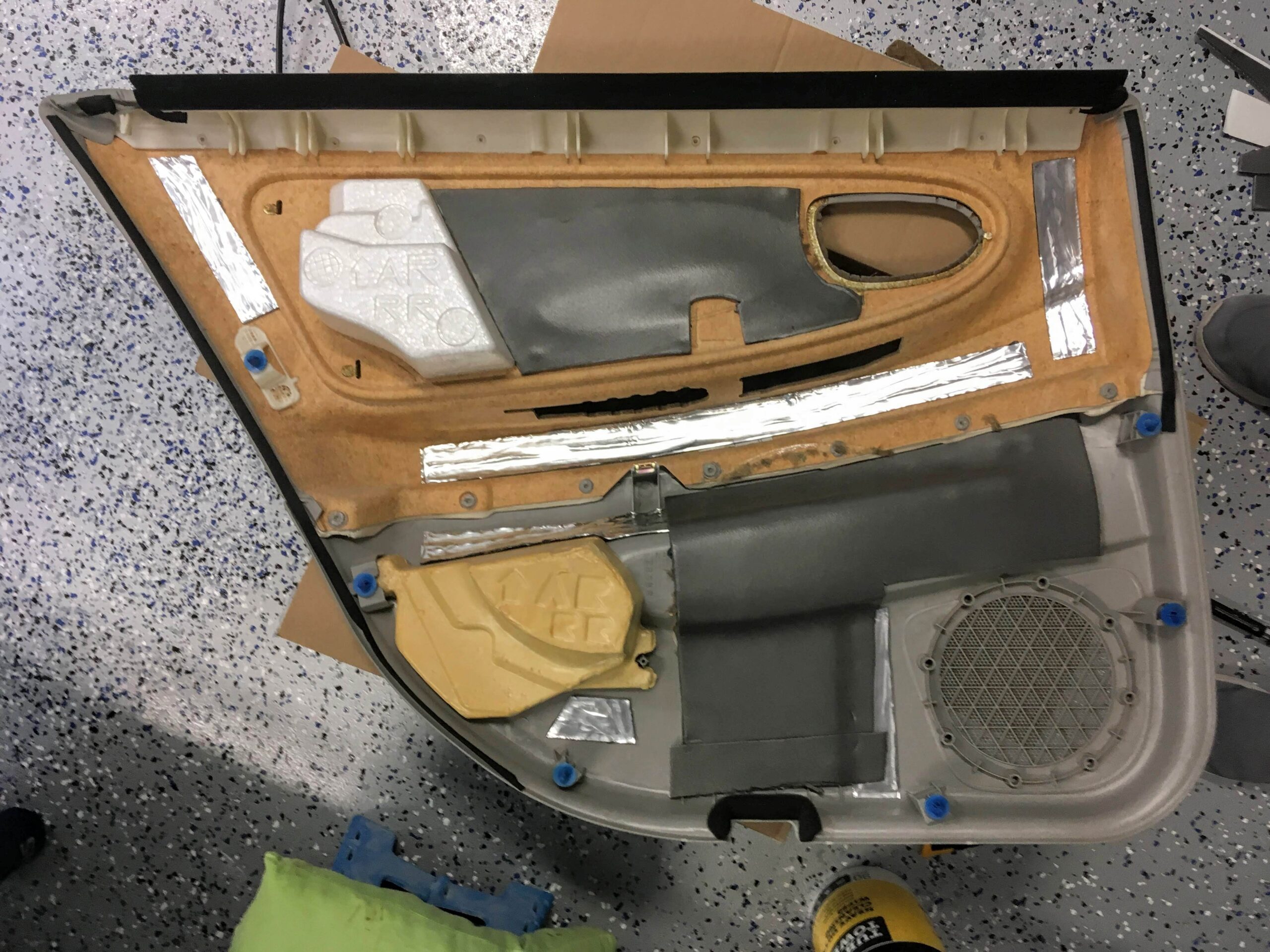
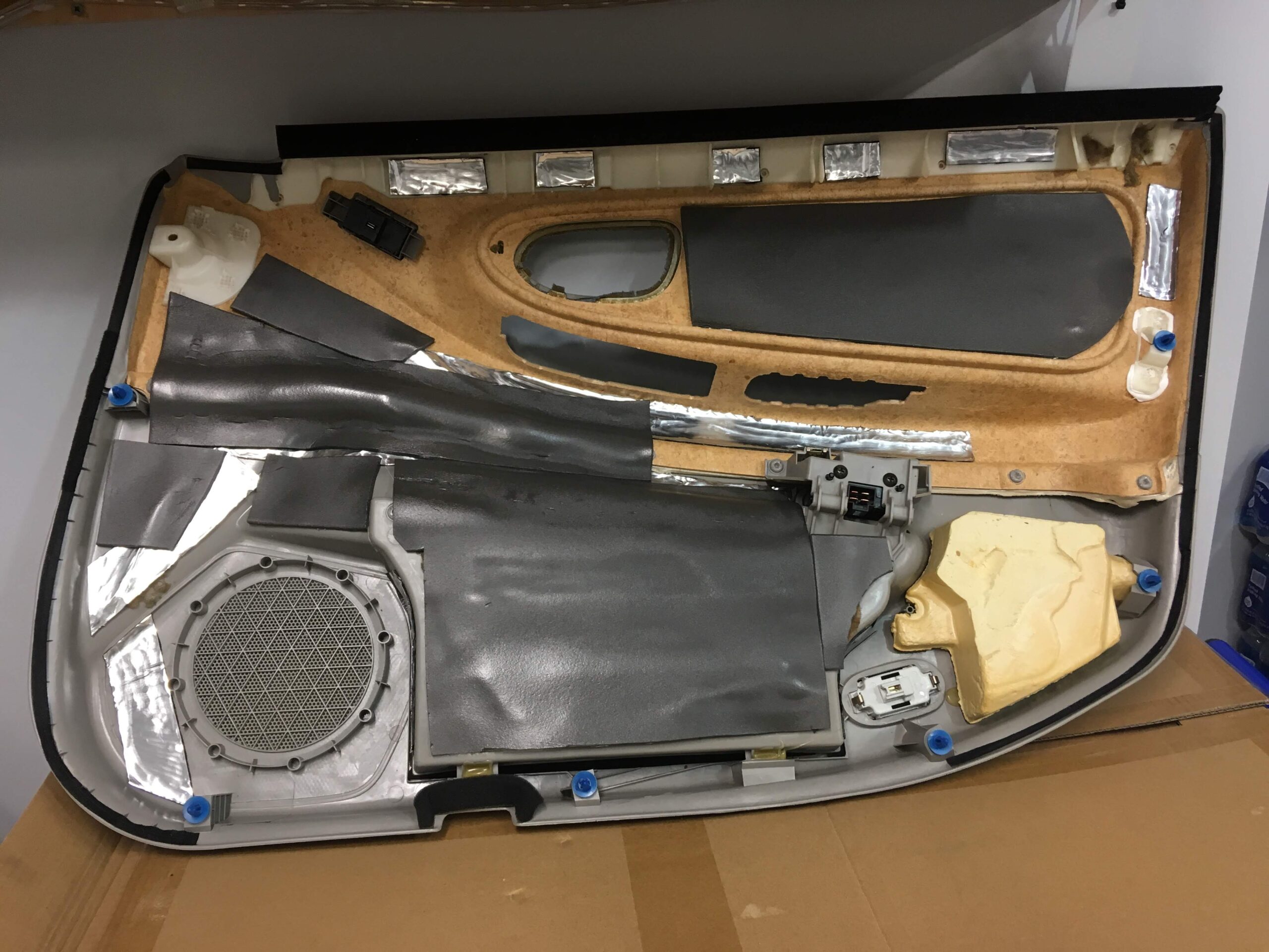
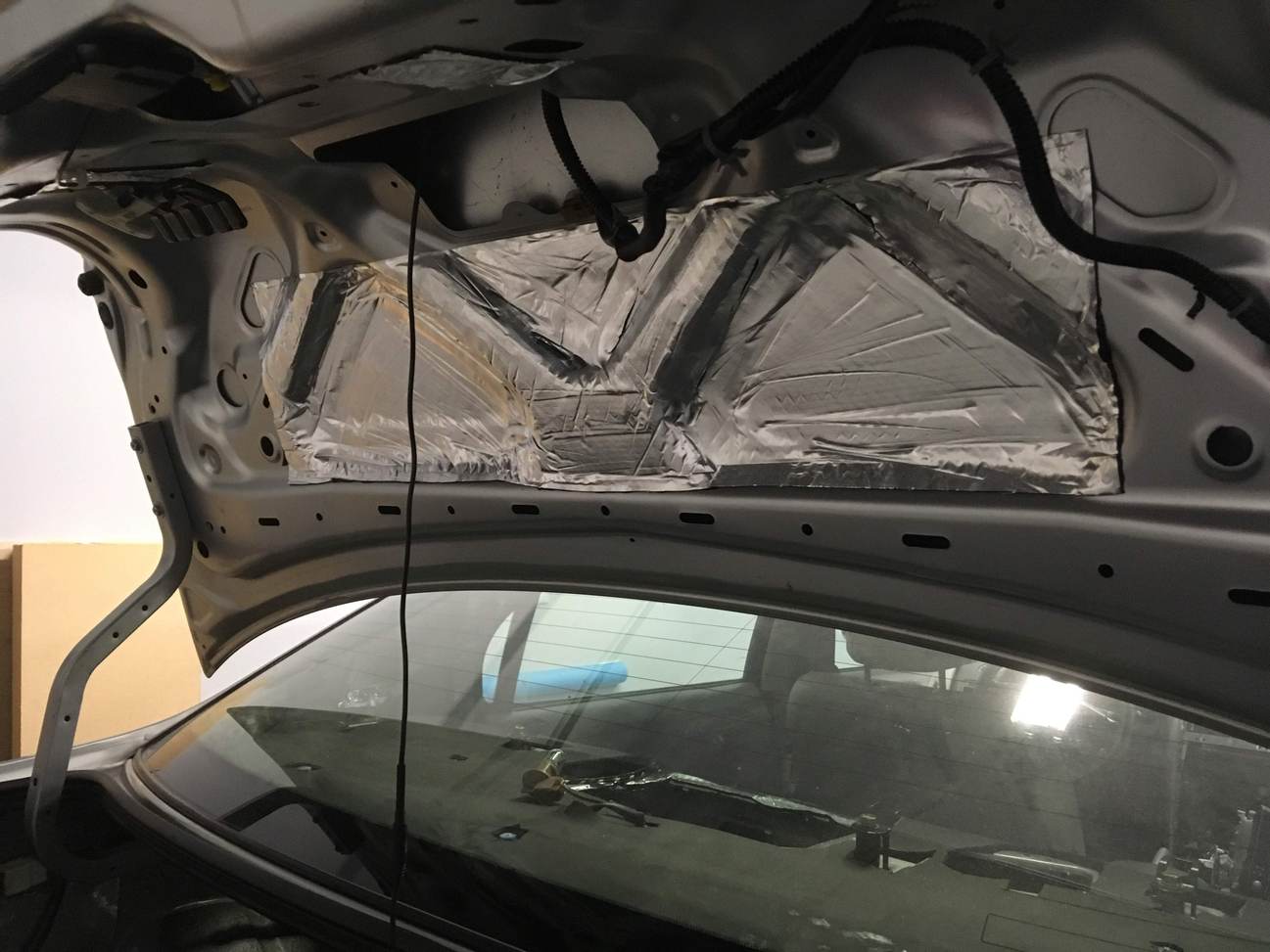
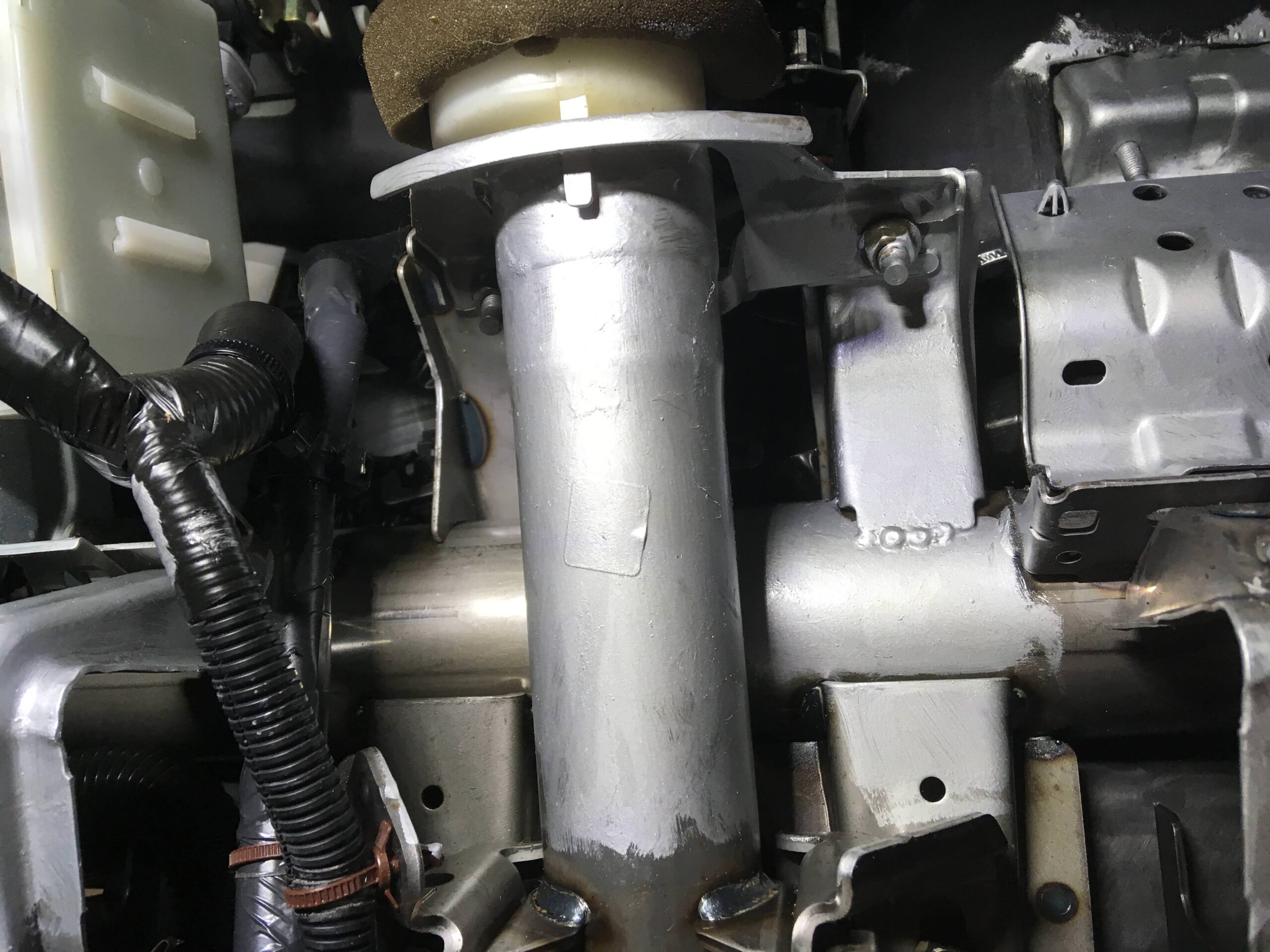
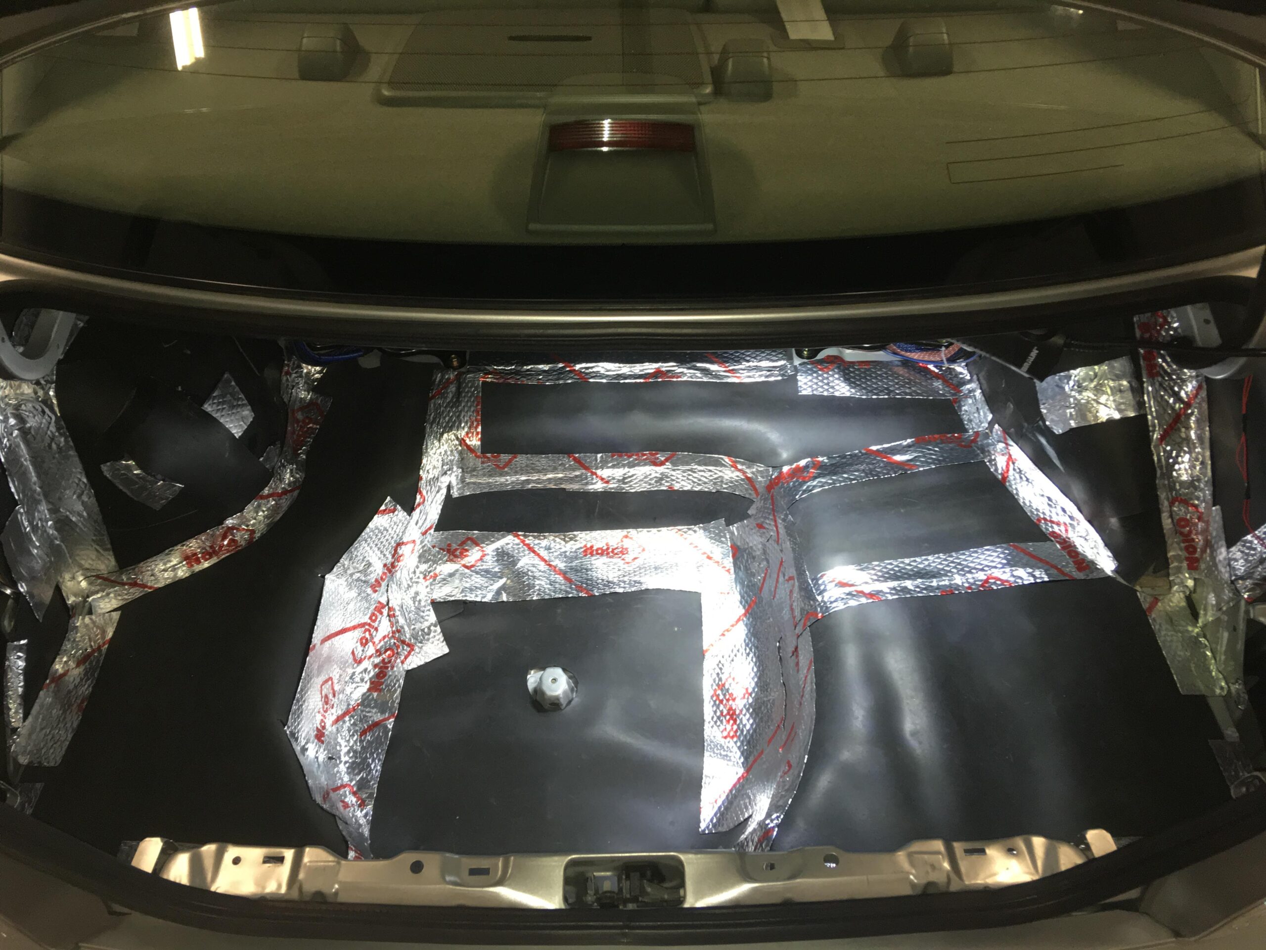
Mask a lot of areas. Afterward tape the aluminum foil on top. This will allow easier removal of the first layers of fiberglass. Cover a lot of your interior and car in general, with some Kraft paper, anything that even has the remote chance of getting fiberglass resin dripped onto it.
I don’t have pictures of the aluminum foil or laying the fiberglass. See tutorials on how to lay fiberglass, that’s a whole new thread in and of itself.


2) Lay 3-5 layers of fiberglass mat (I did 4 because I was using some lighter density mat)
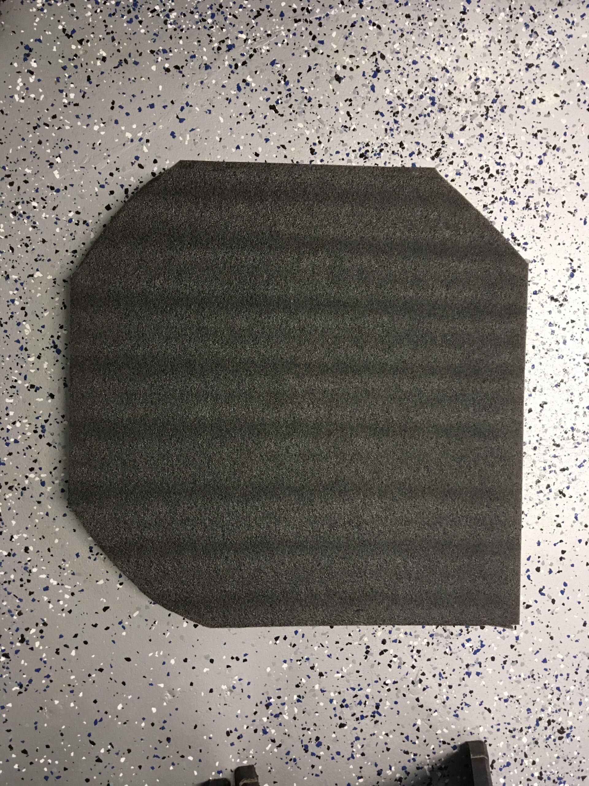
3) After this first layer has cured, remove it and trim the edges to your desired shape and contour, I used a jigsaw.


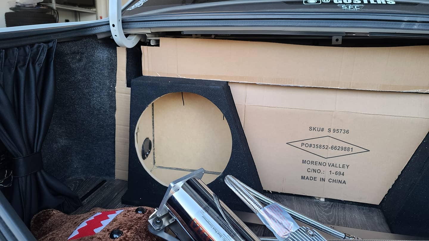
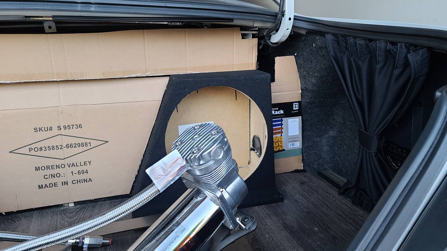
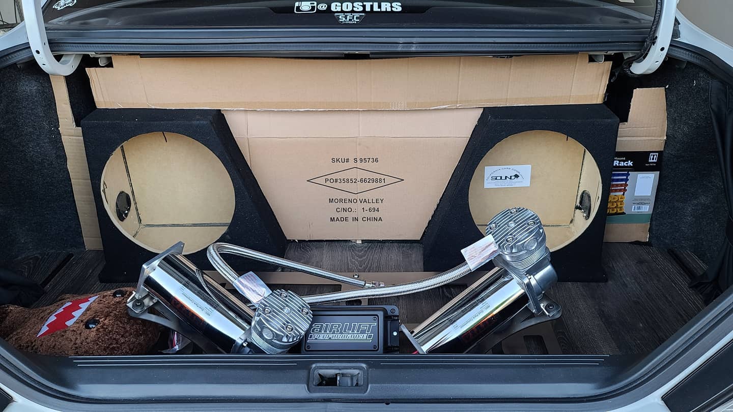
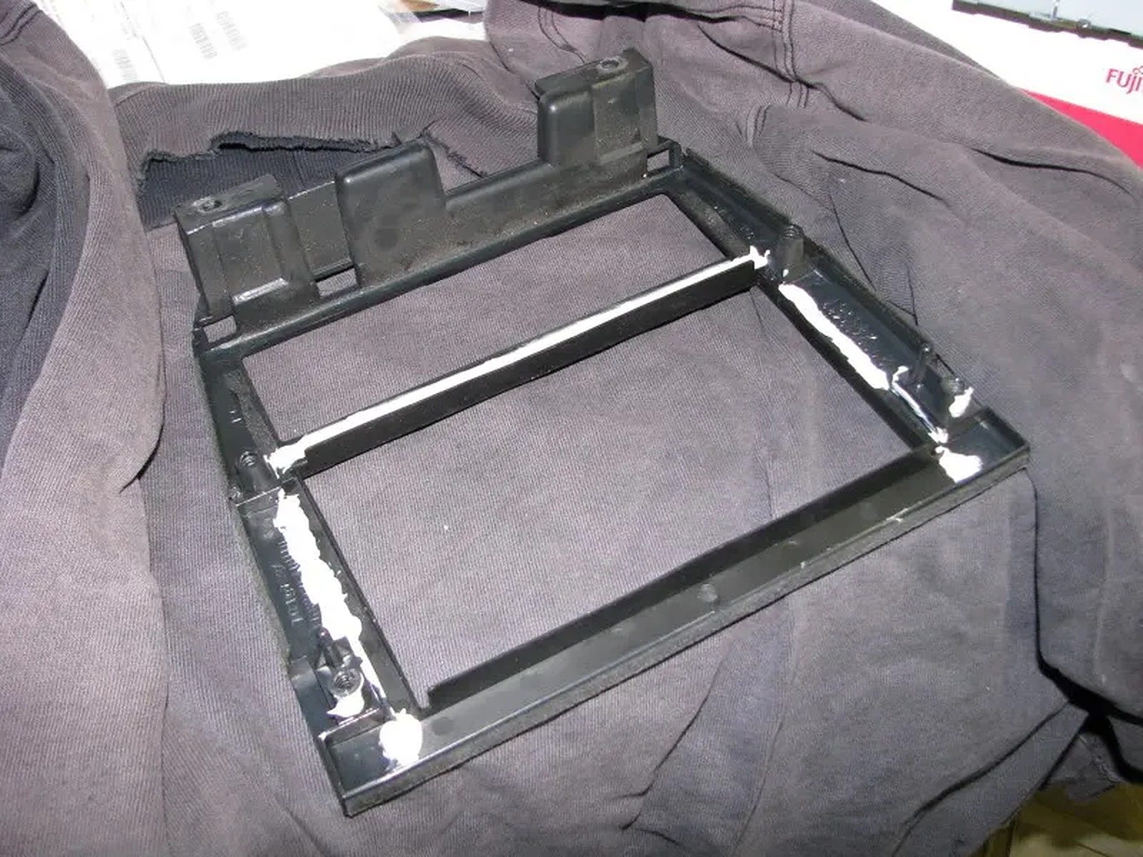
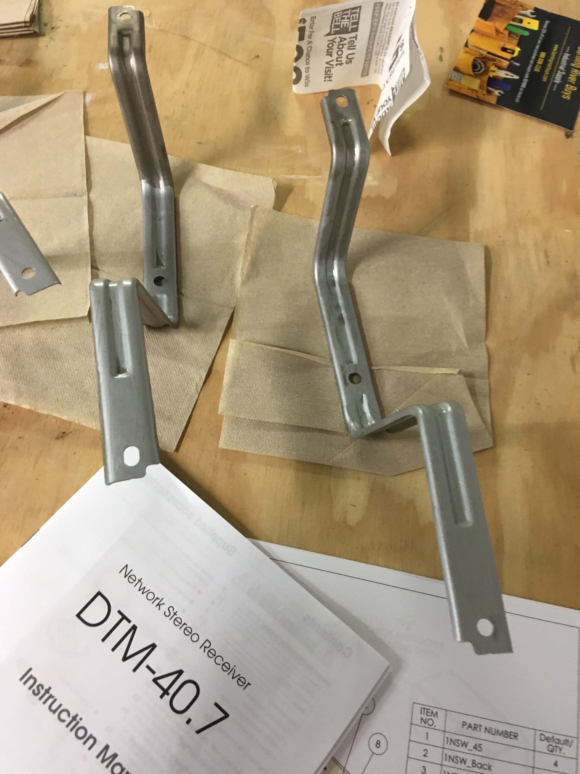
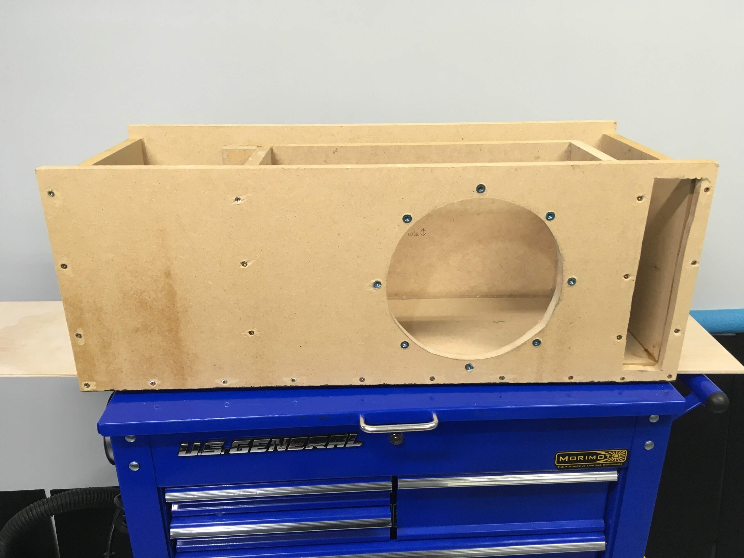
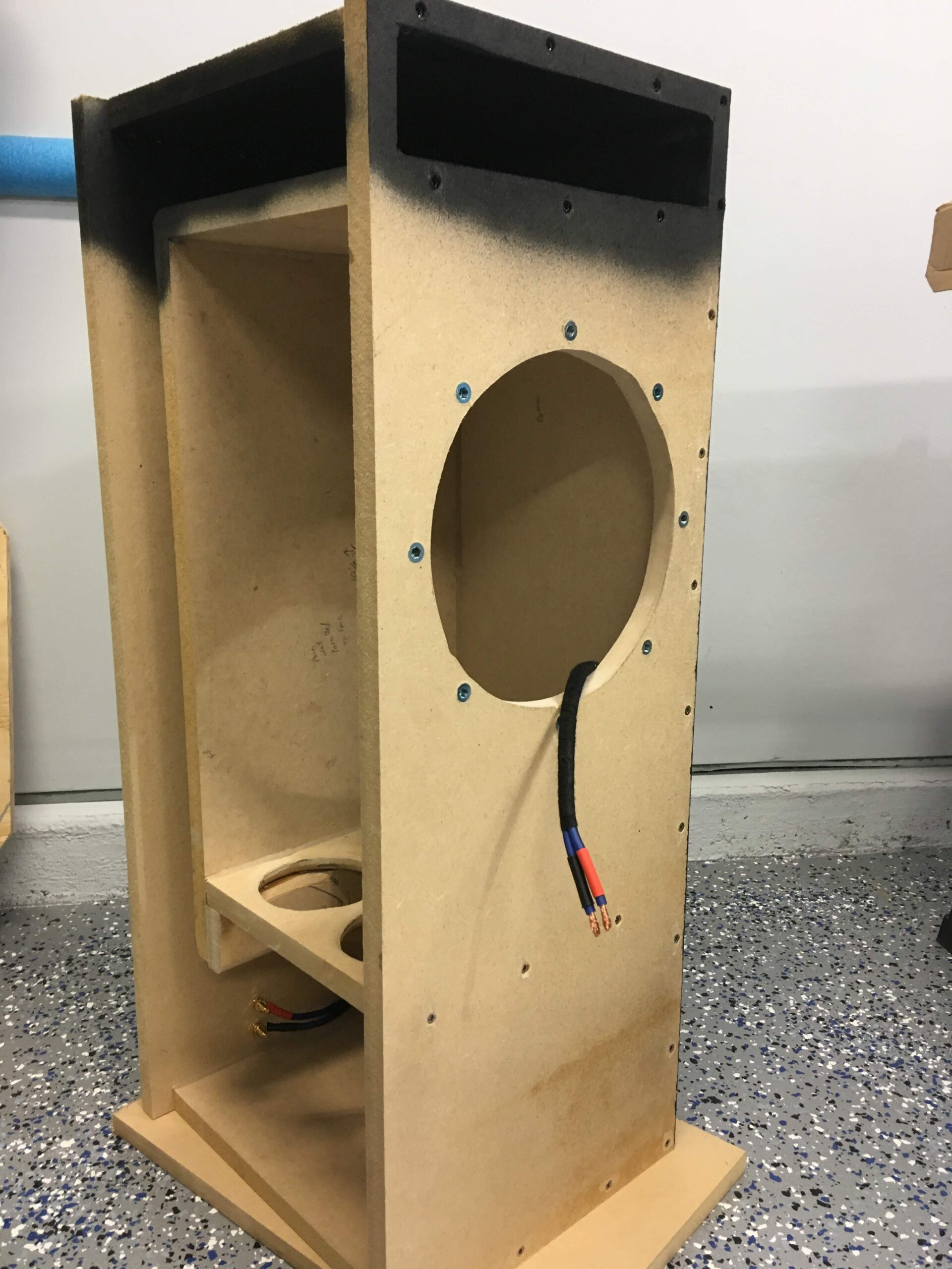
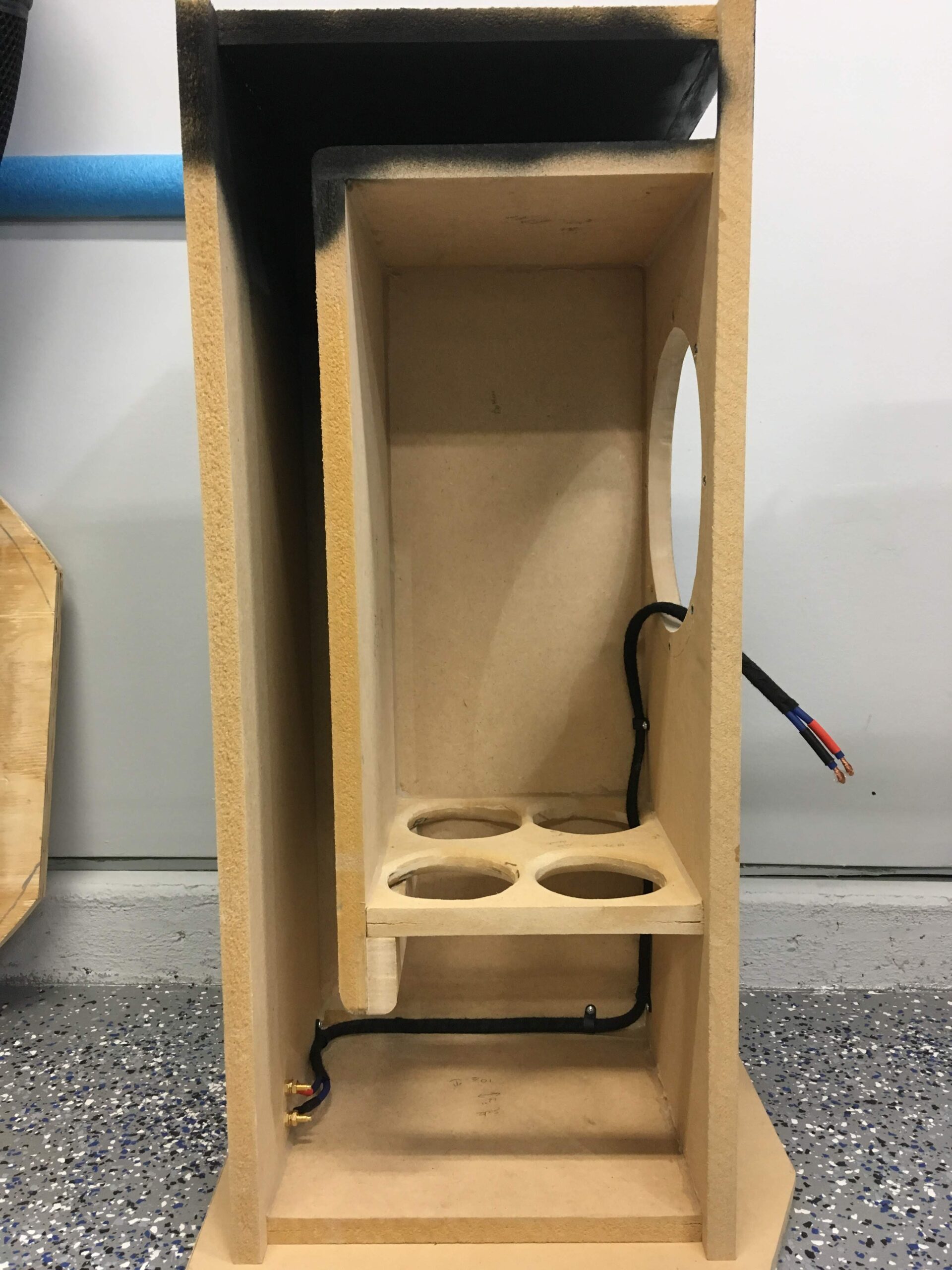
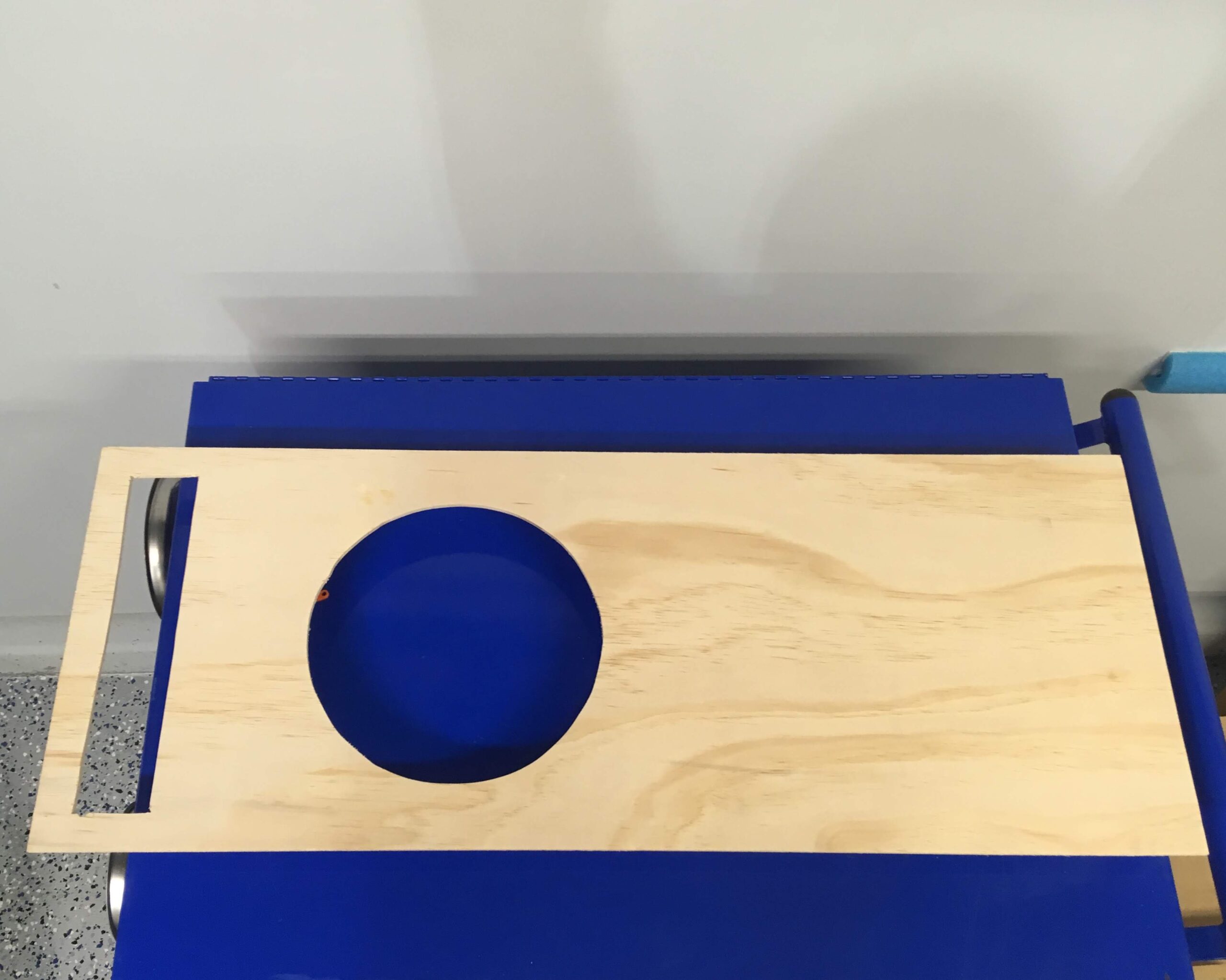
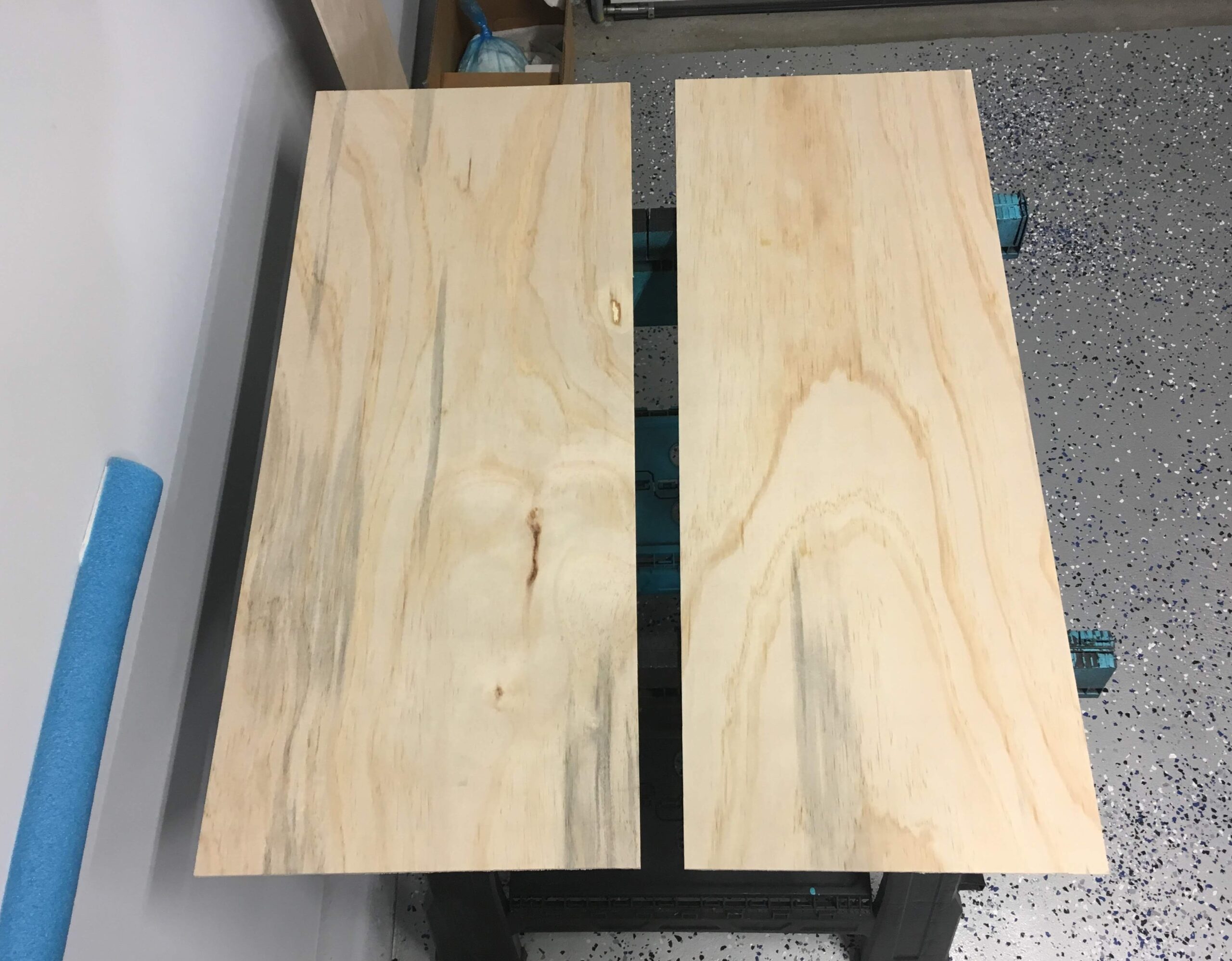
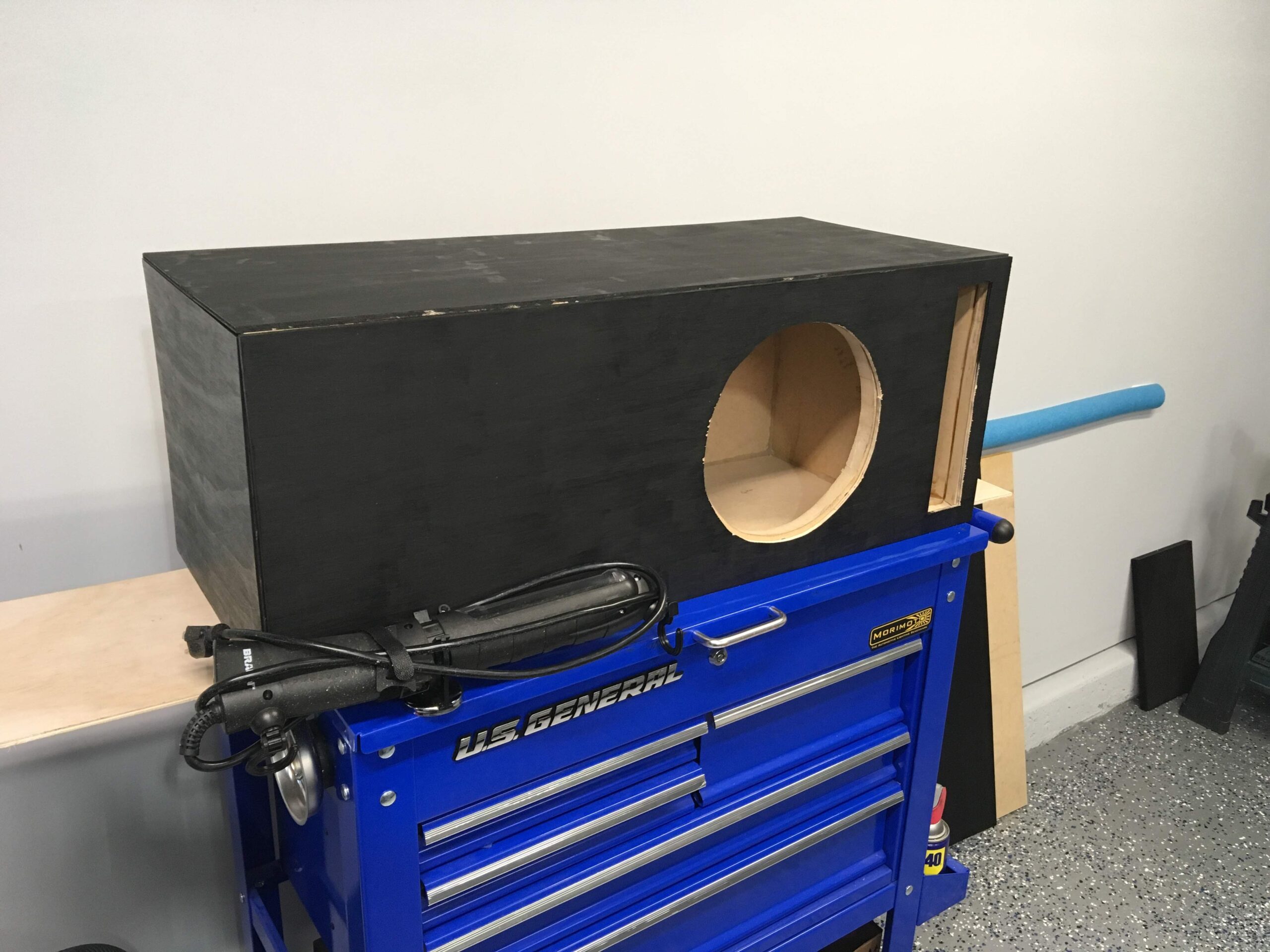
4) Now your mounting ring should be cut, or purchased, you’ll want to cut some pieces to act as leg supports to hold the mounting ring at the required depth (I measured the internal box volume by using packing peanuts and a cardboard box with my required internal volume [0.75 cu. ft])

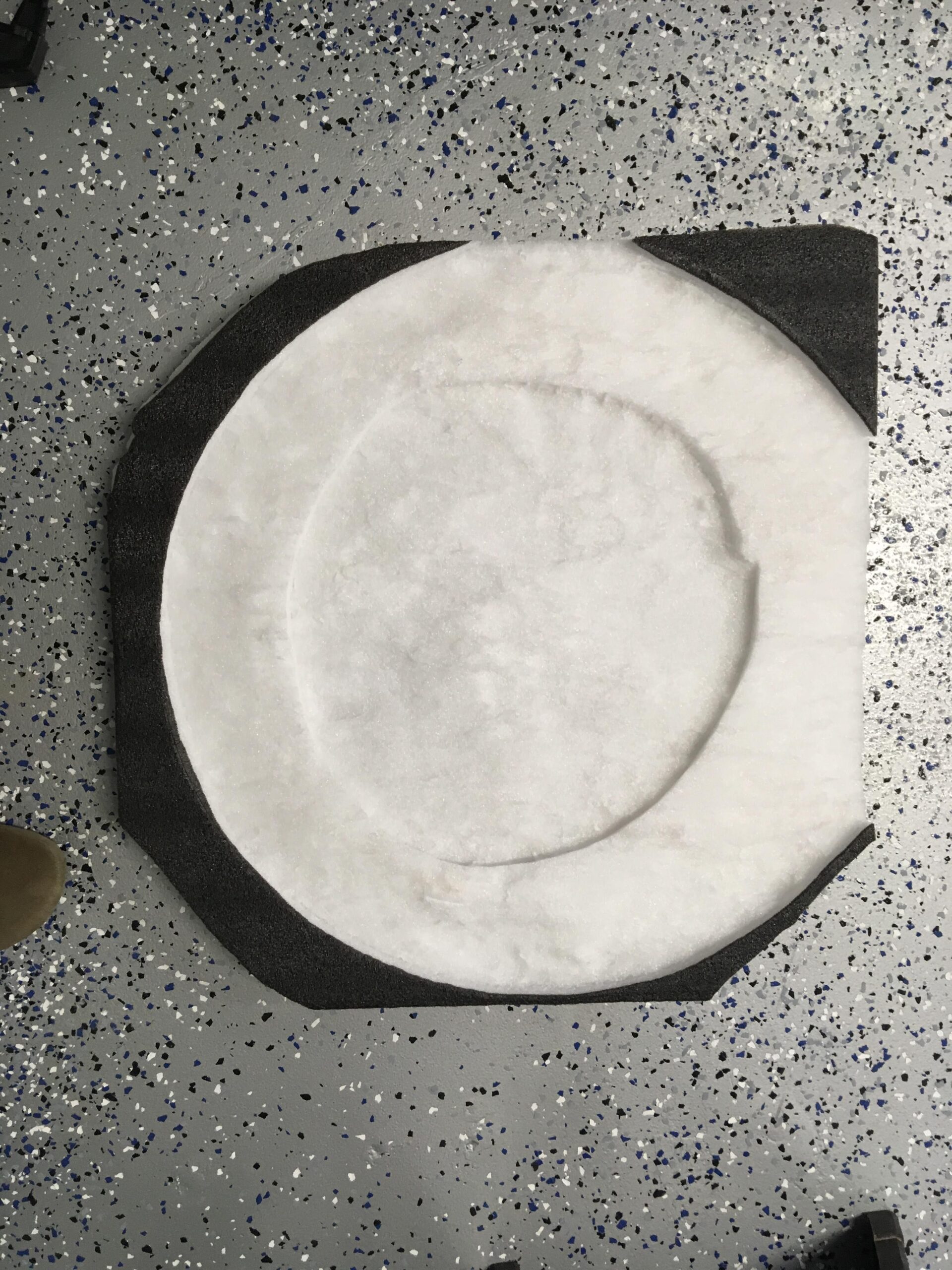
5) Use the fleece fabric and stretch it over your mounting ring to the back of the shell and use the adhesive spray to hold it to the entire edge of the shell as well as to the outer edge of the mounting ring.
6) Lay resin onto the entire fleece (except for where the hole of the mounting ring is) and before it hardens, use a razor to trim the fleece from the mounting ring face.
7) After the fleece hardens, lay 3-5 layers of fiberglass over the fleece.

8) The final stretch…Once it all hardens: sand, trim, grind, fill, primer, whatever you have to do to finish it up. I had to do a lot of trimming since it was my first time using fiberglass, I made a mess with my edges so I did some grinding to make it sit flush in my trunk.
9) Unless you are painting, go ahead and wrap the box with your carpet or wool using the super 77 adhesive mounting spray.
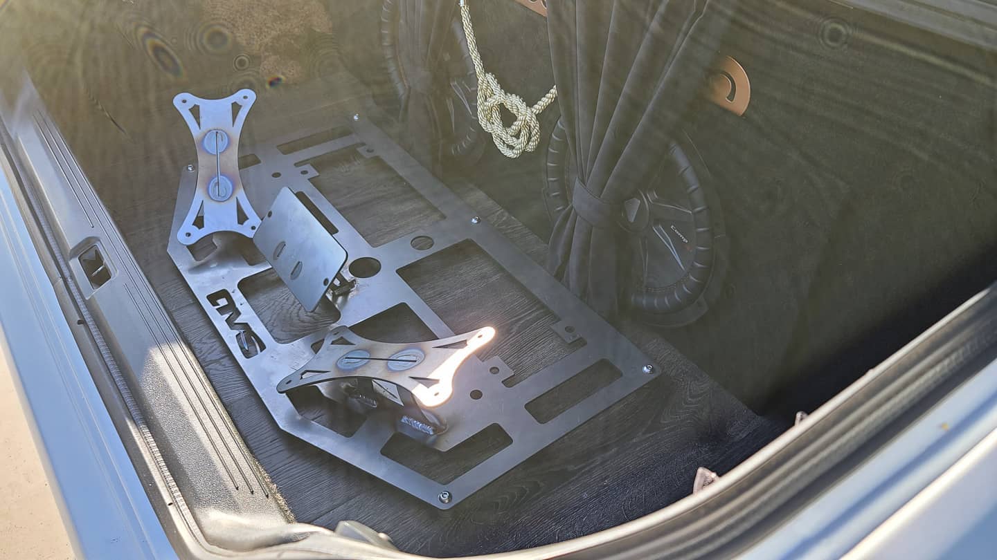
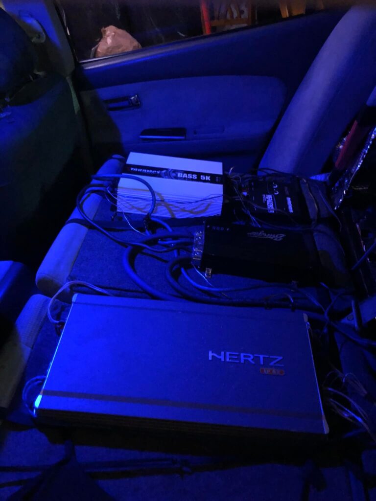
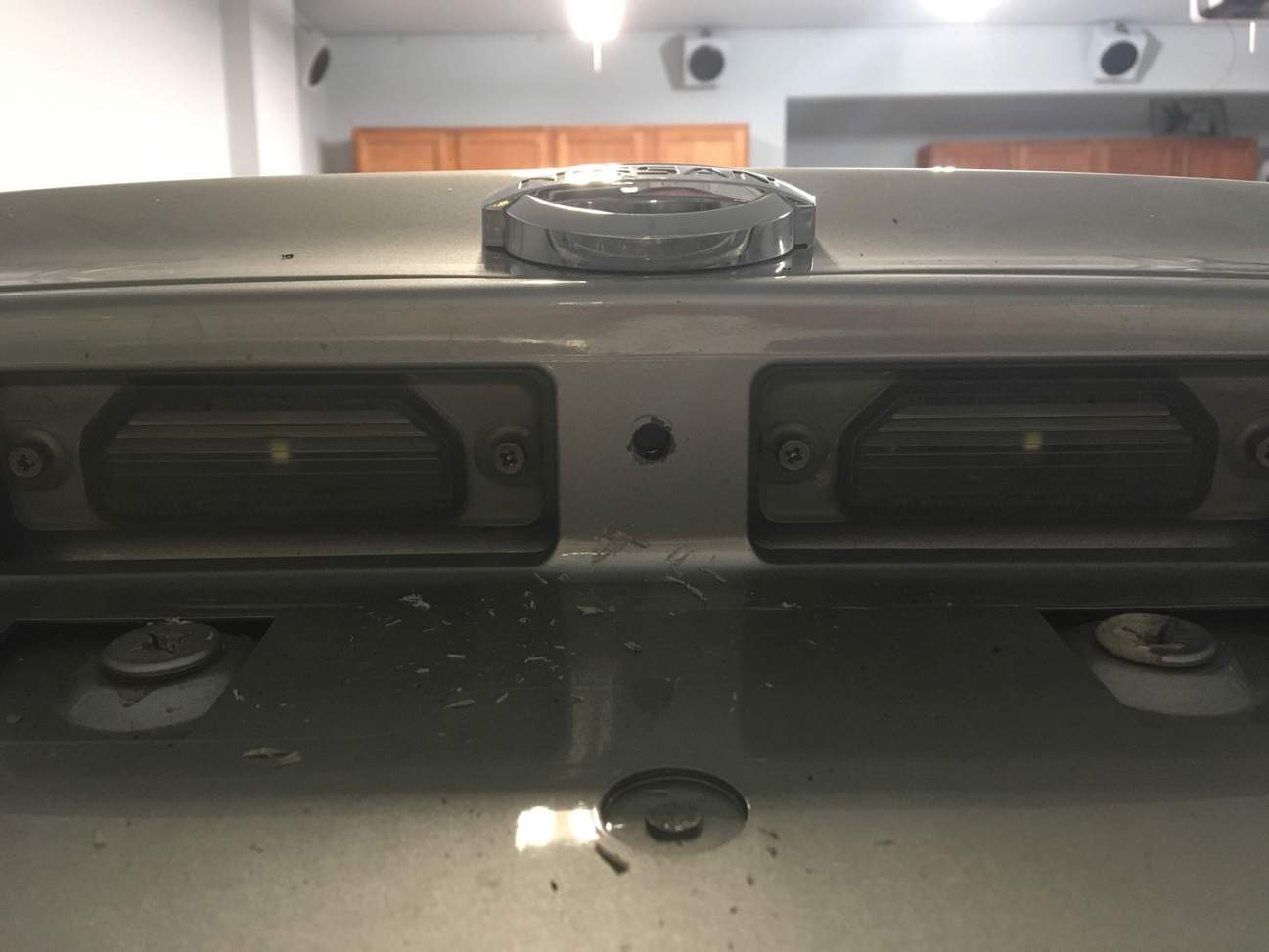
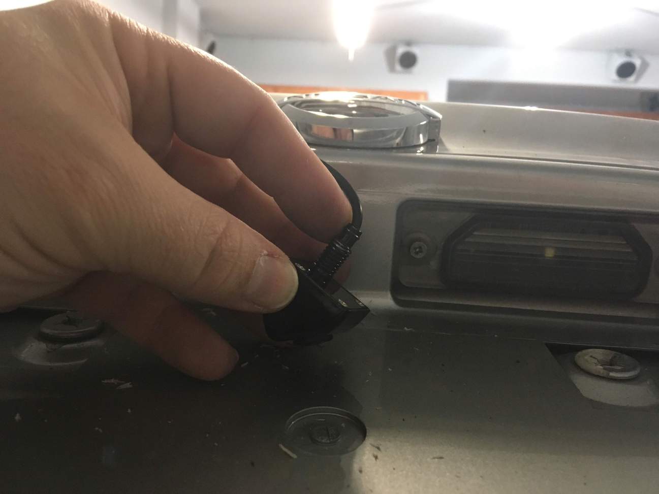
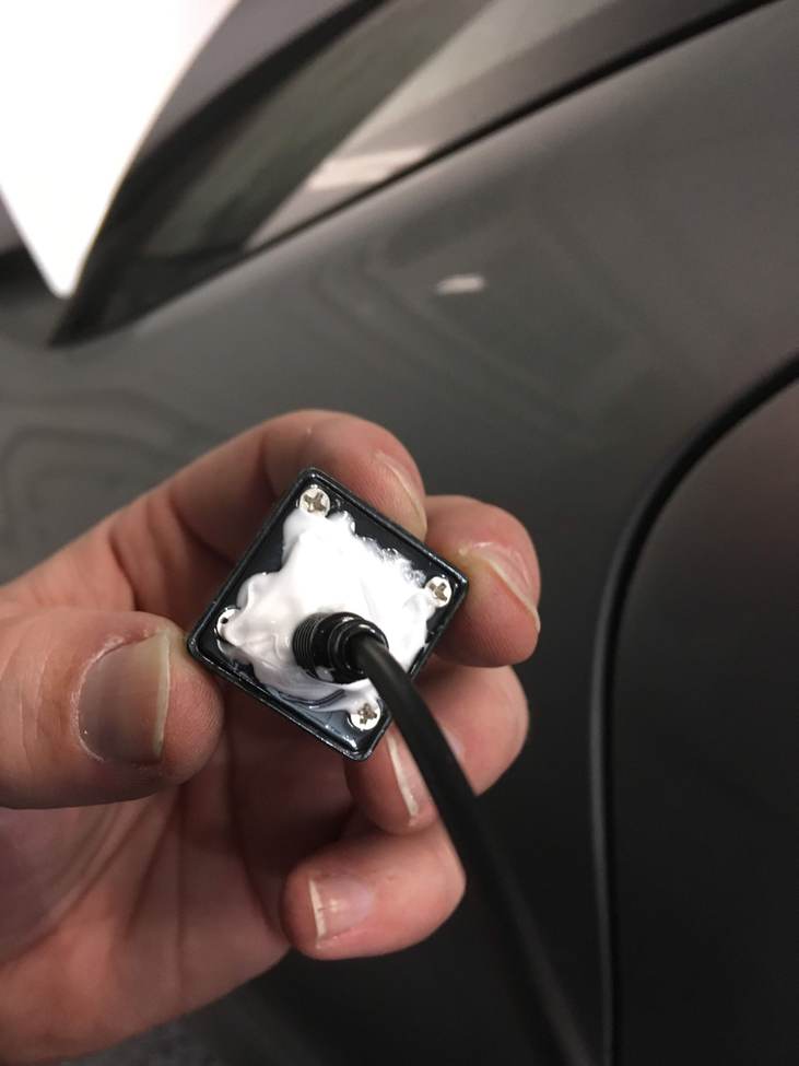
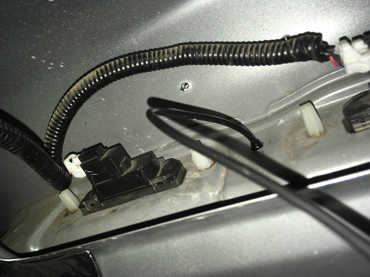
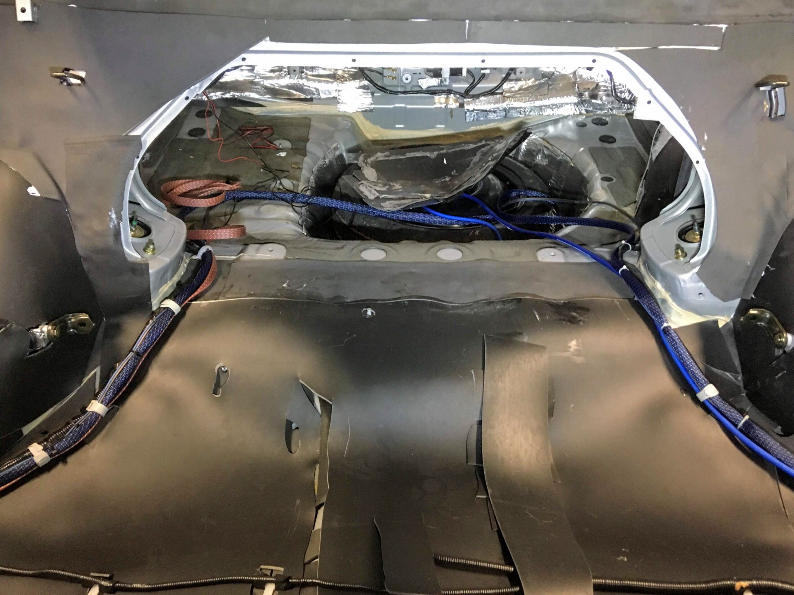
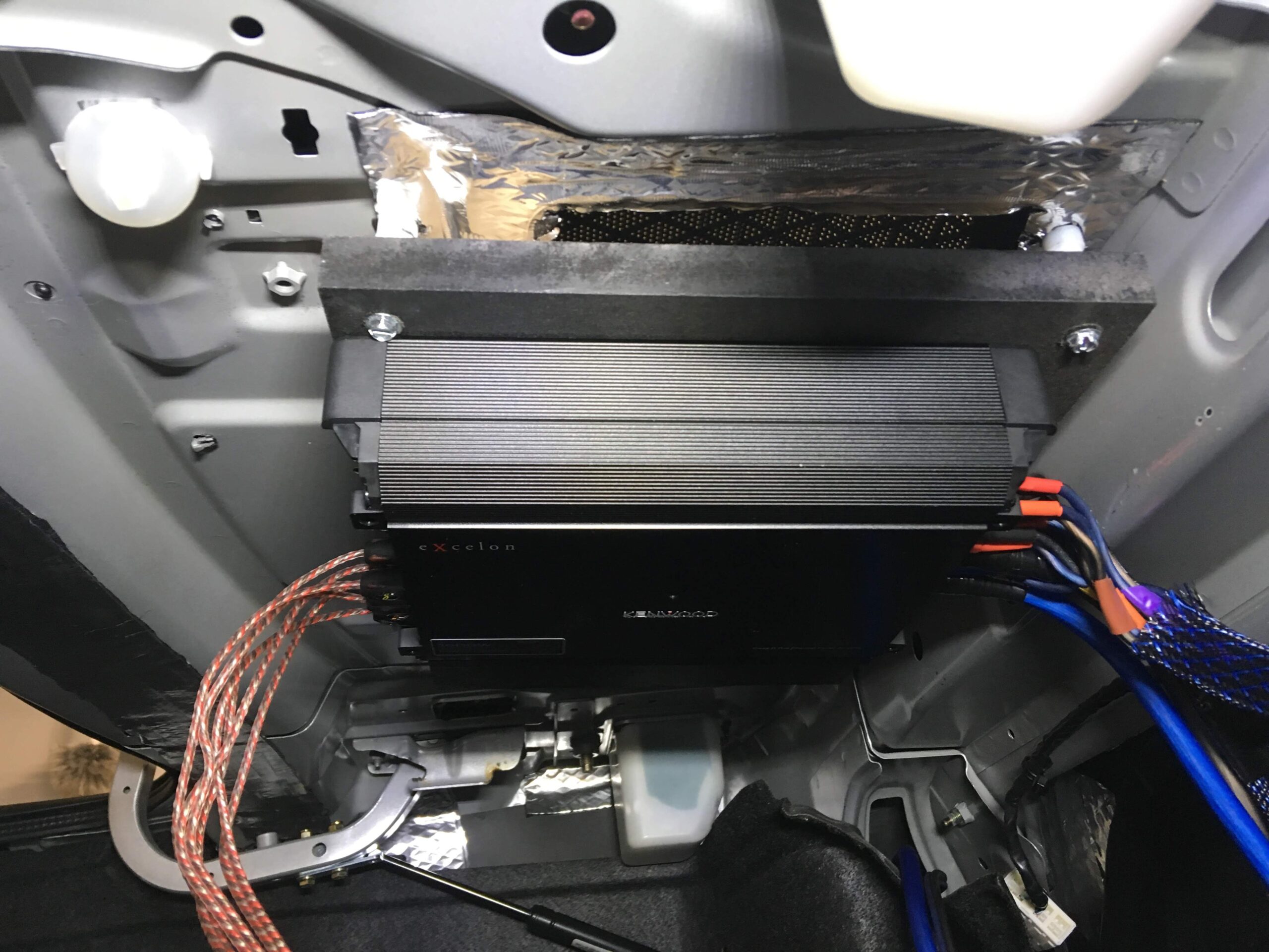
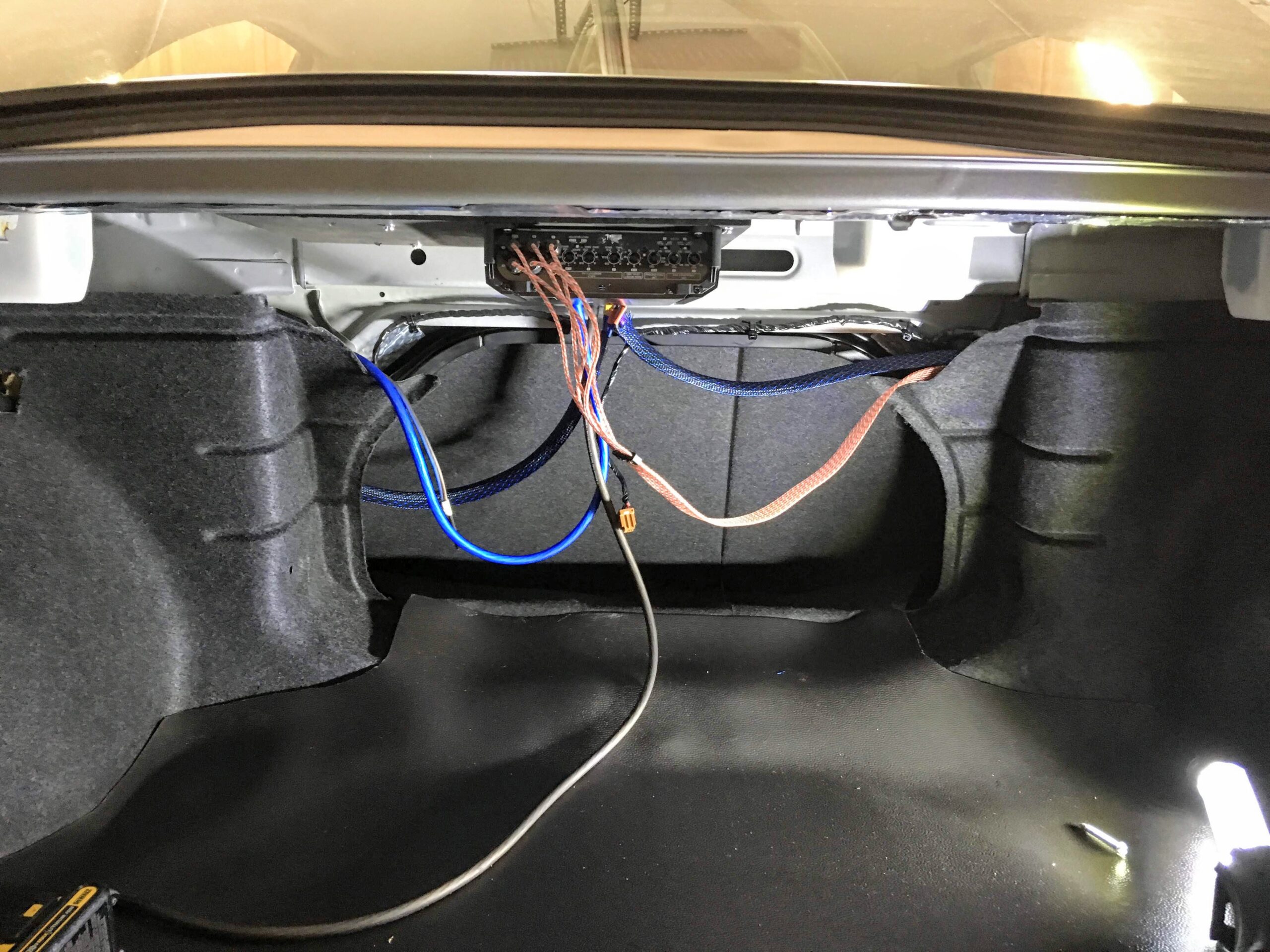
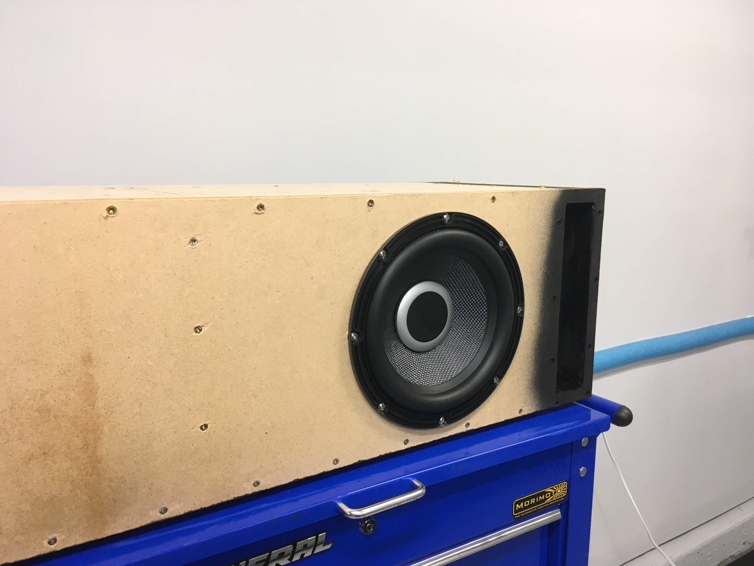
10) Mount your sub, I drilled a hole and silicones the edges after I ran my wires through the hole. And mounted my amp in the spare tire on a wooden board cut to fit.
Enjoy the music and satisfaction of your custom box!


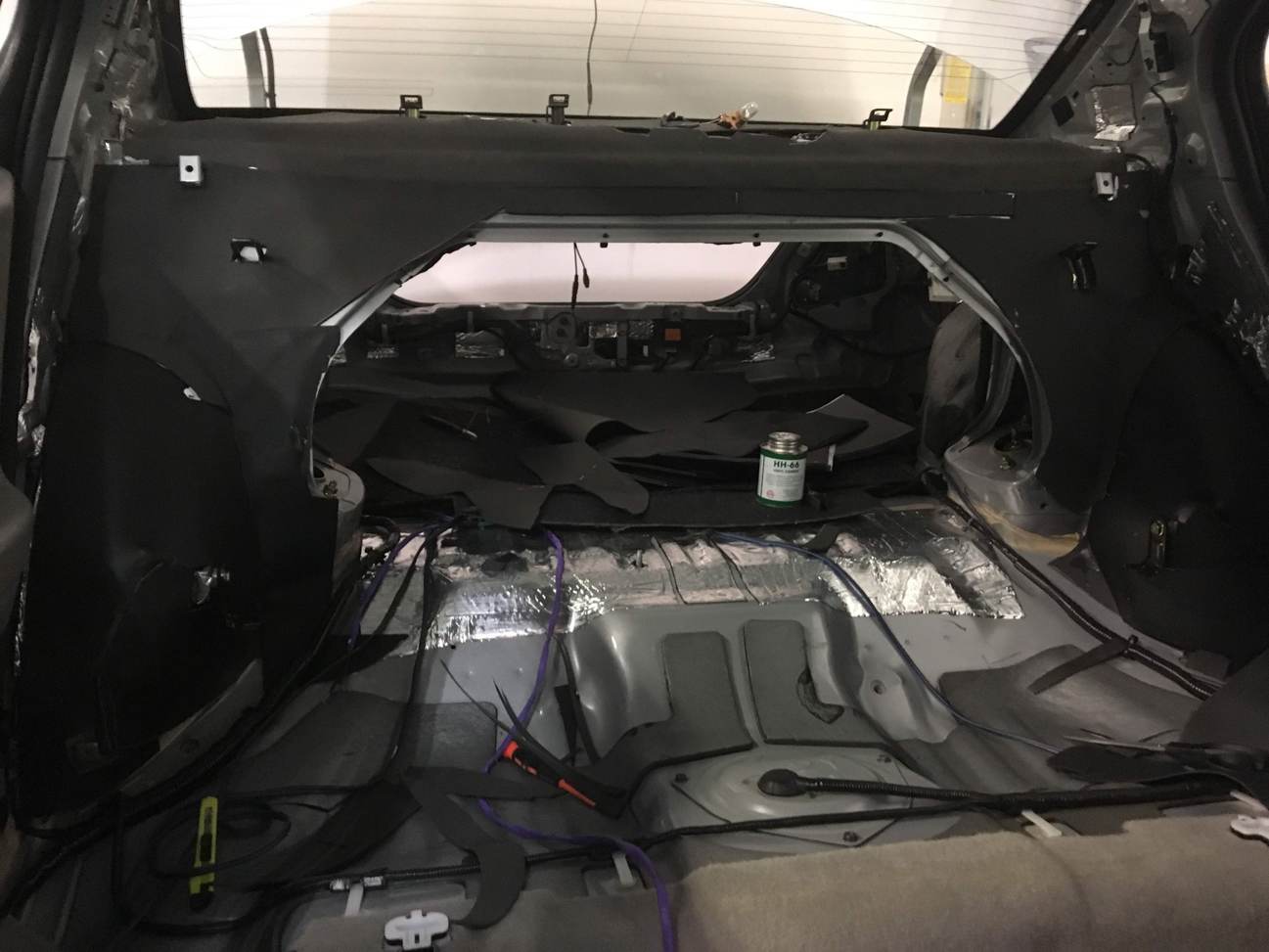
![]()

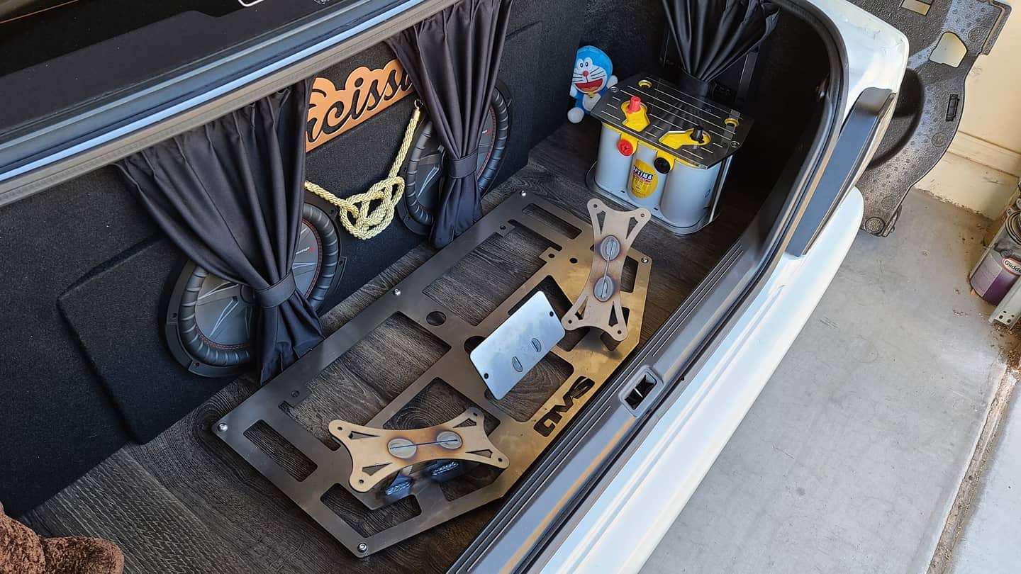
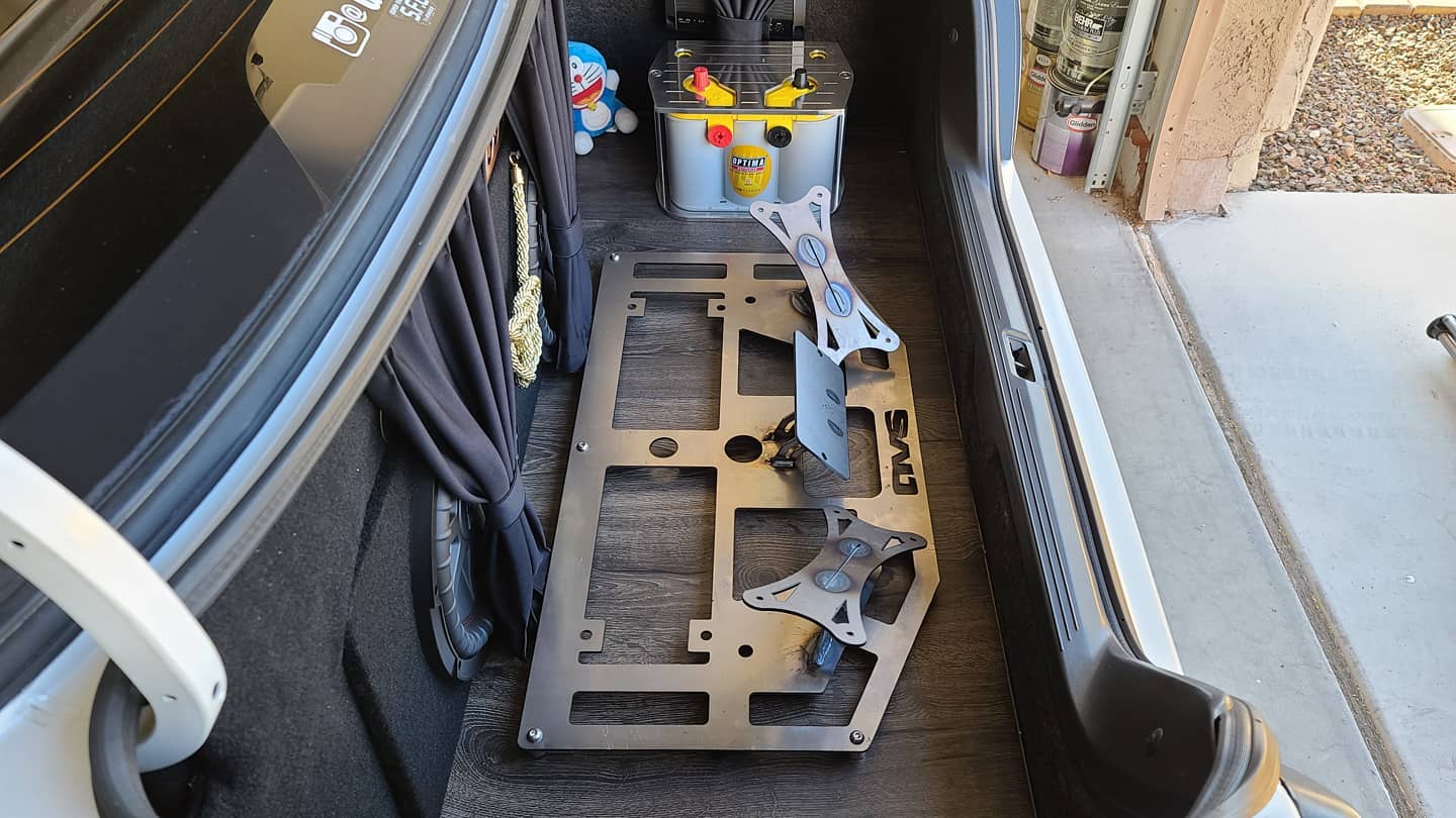
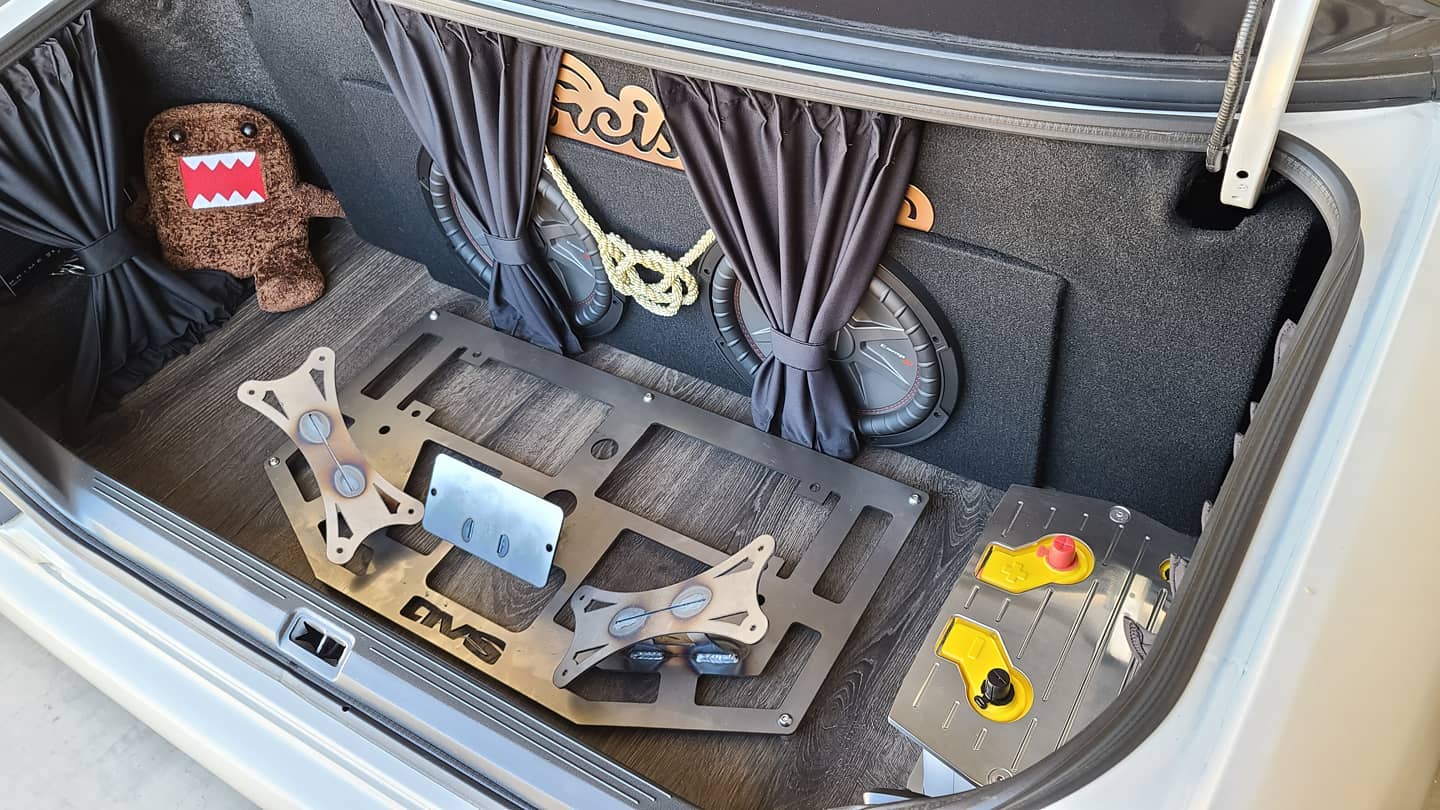
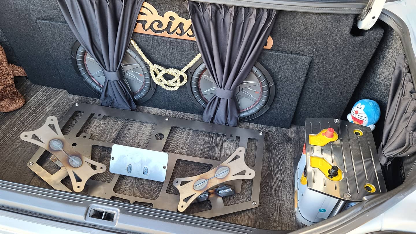
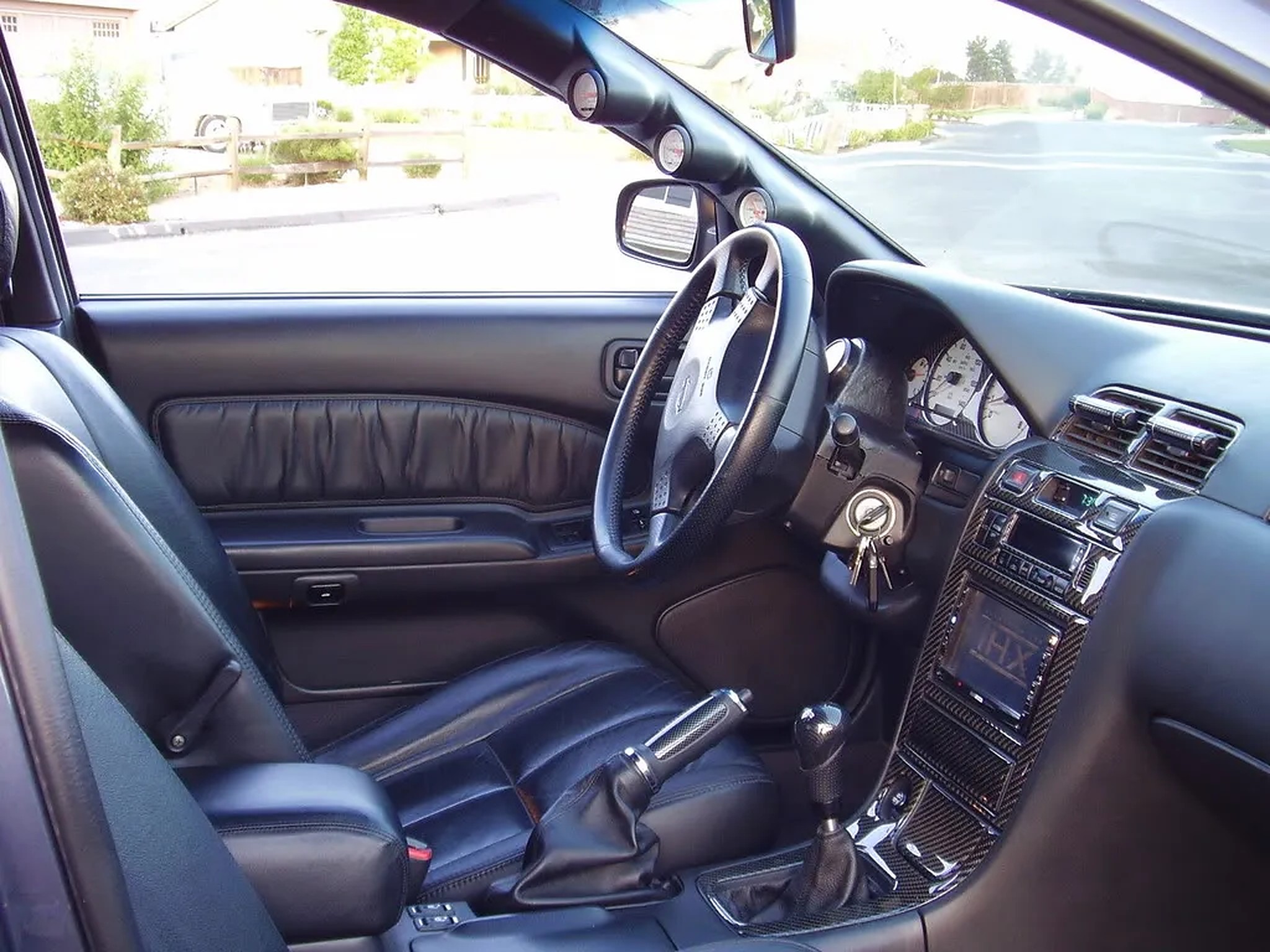
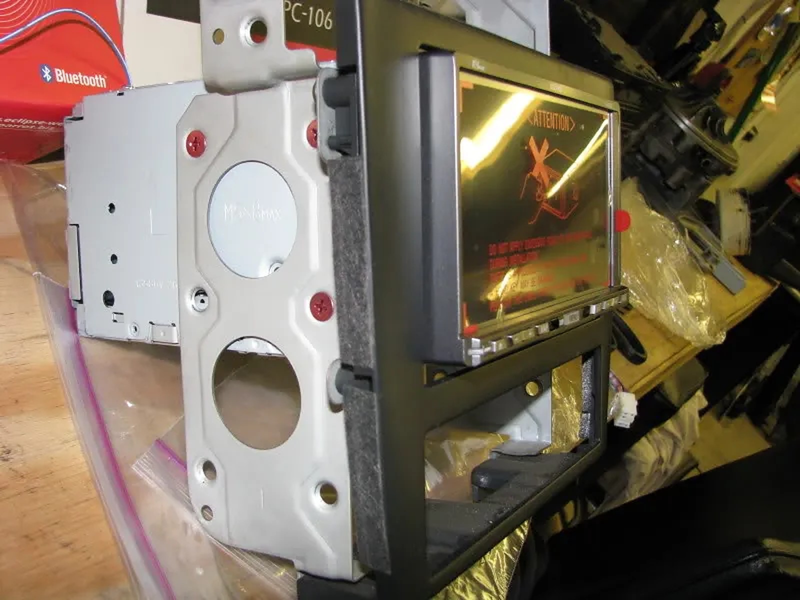
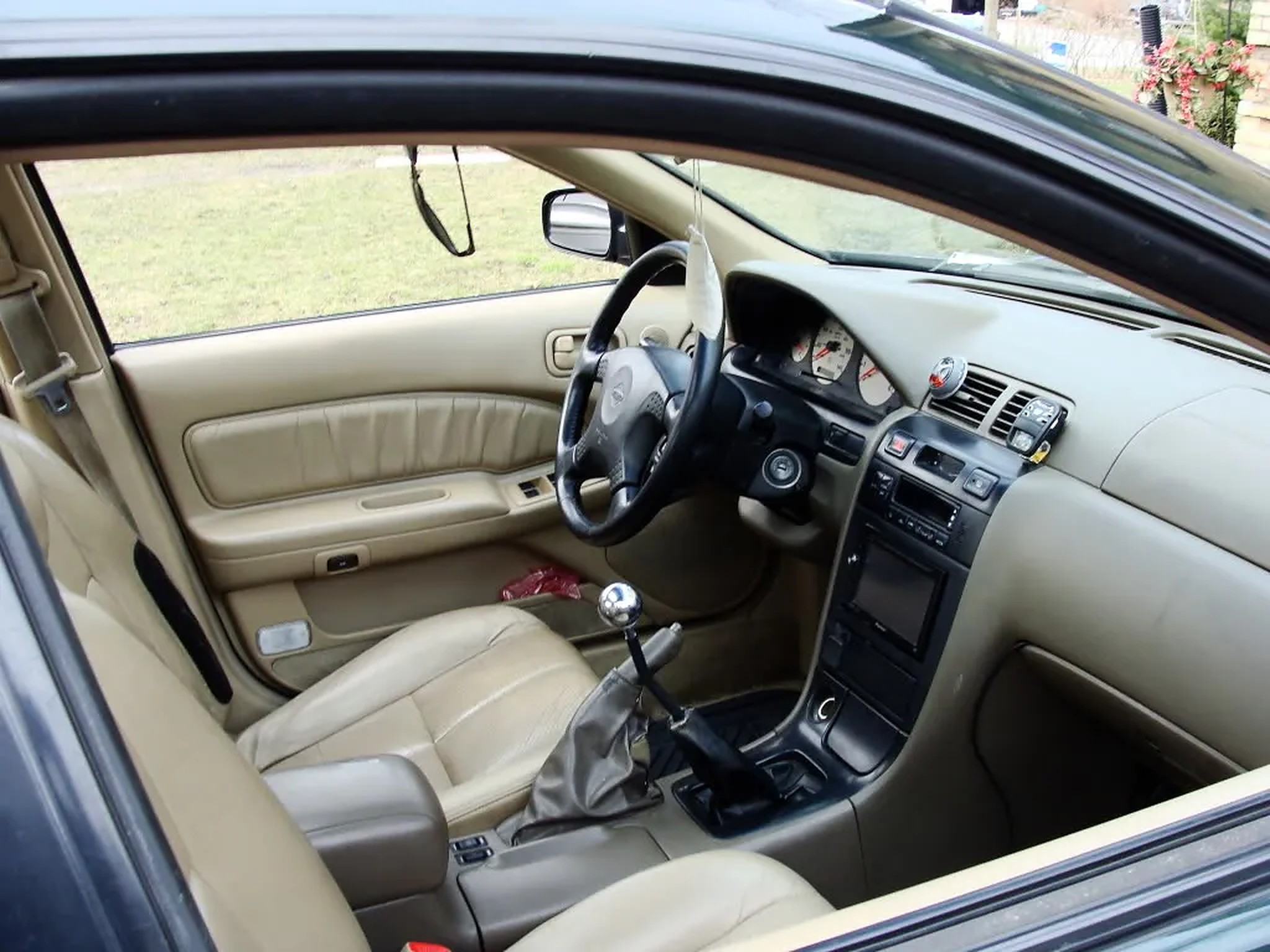
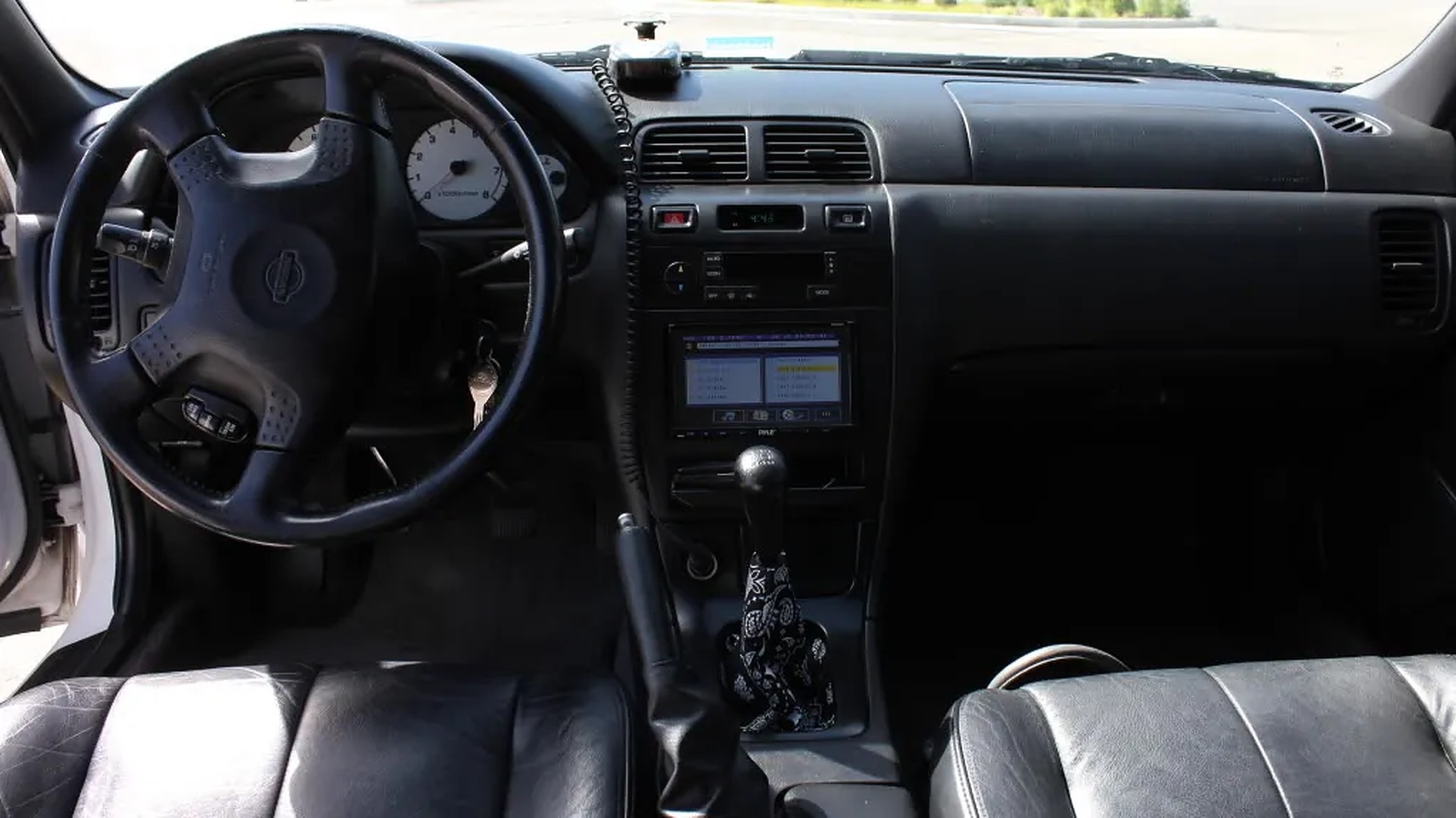
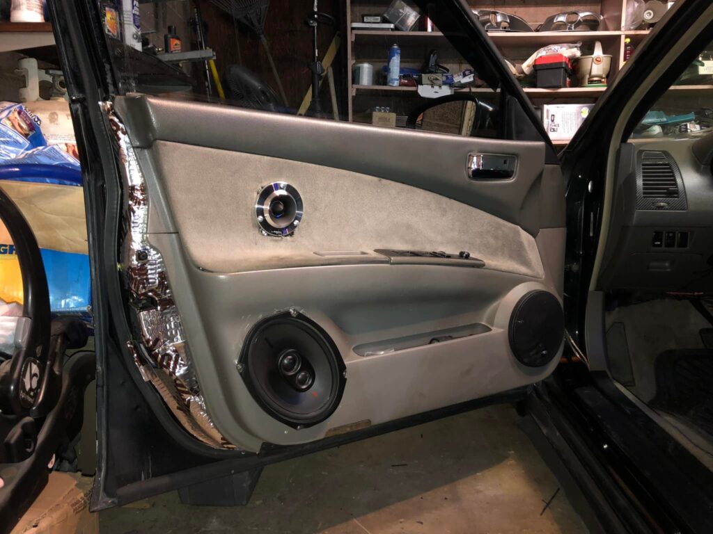
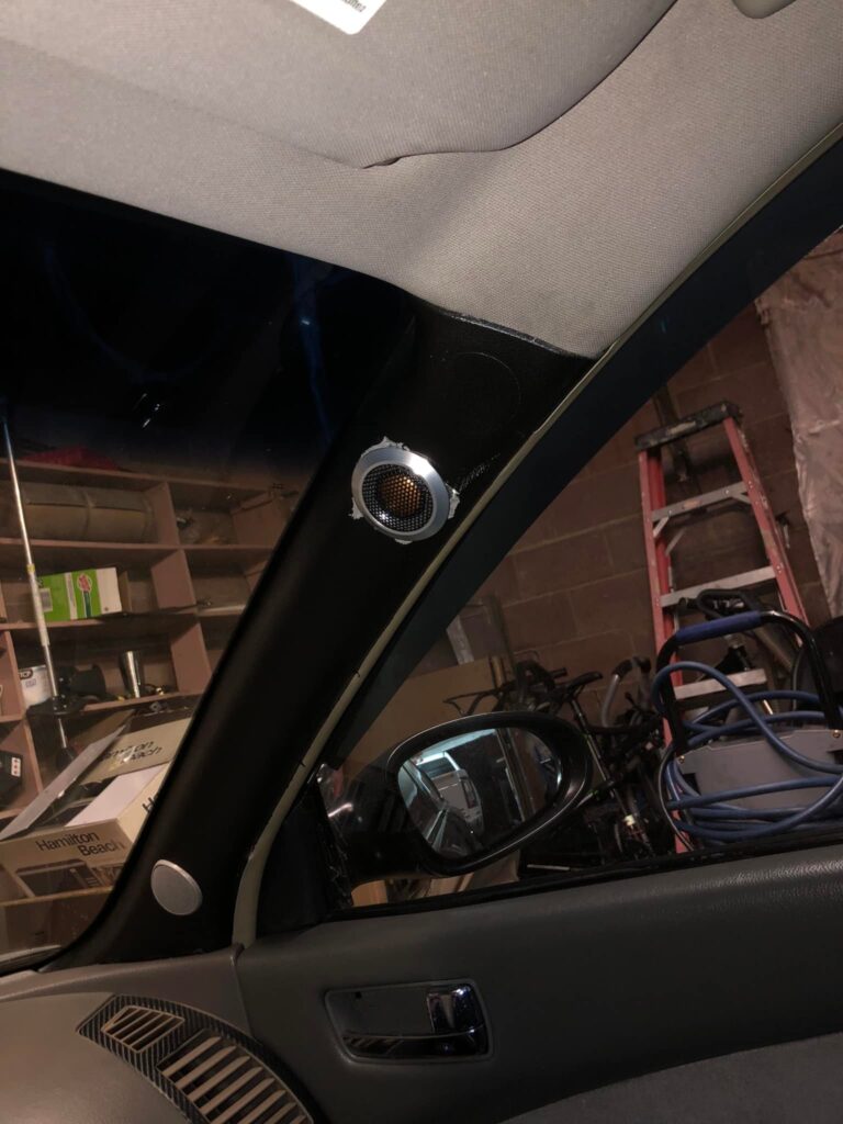
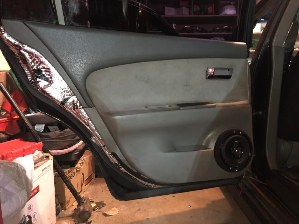
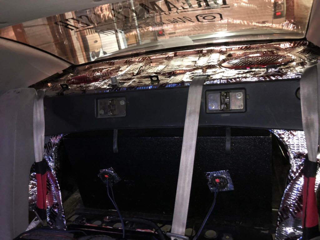
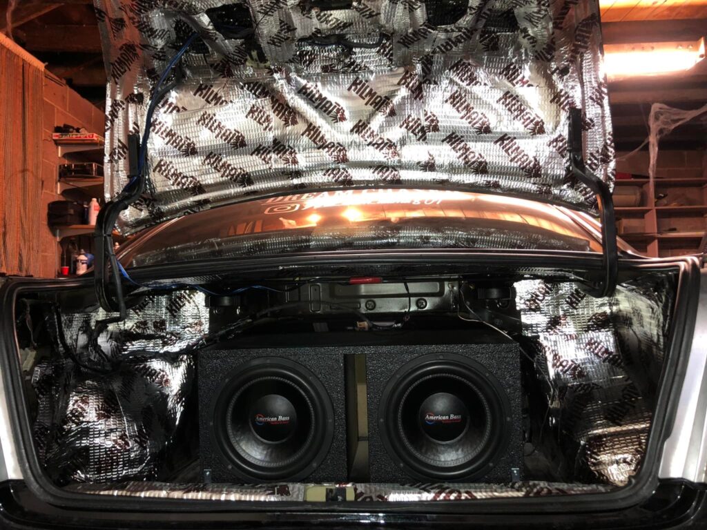
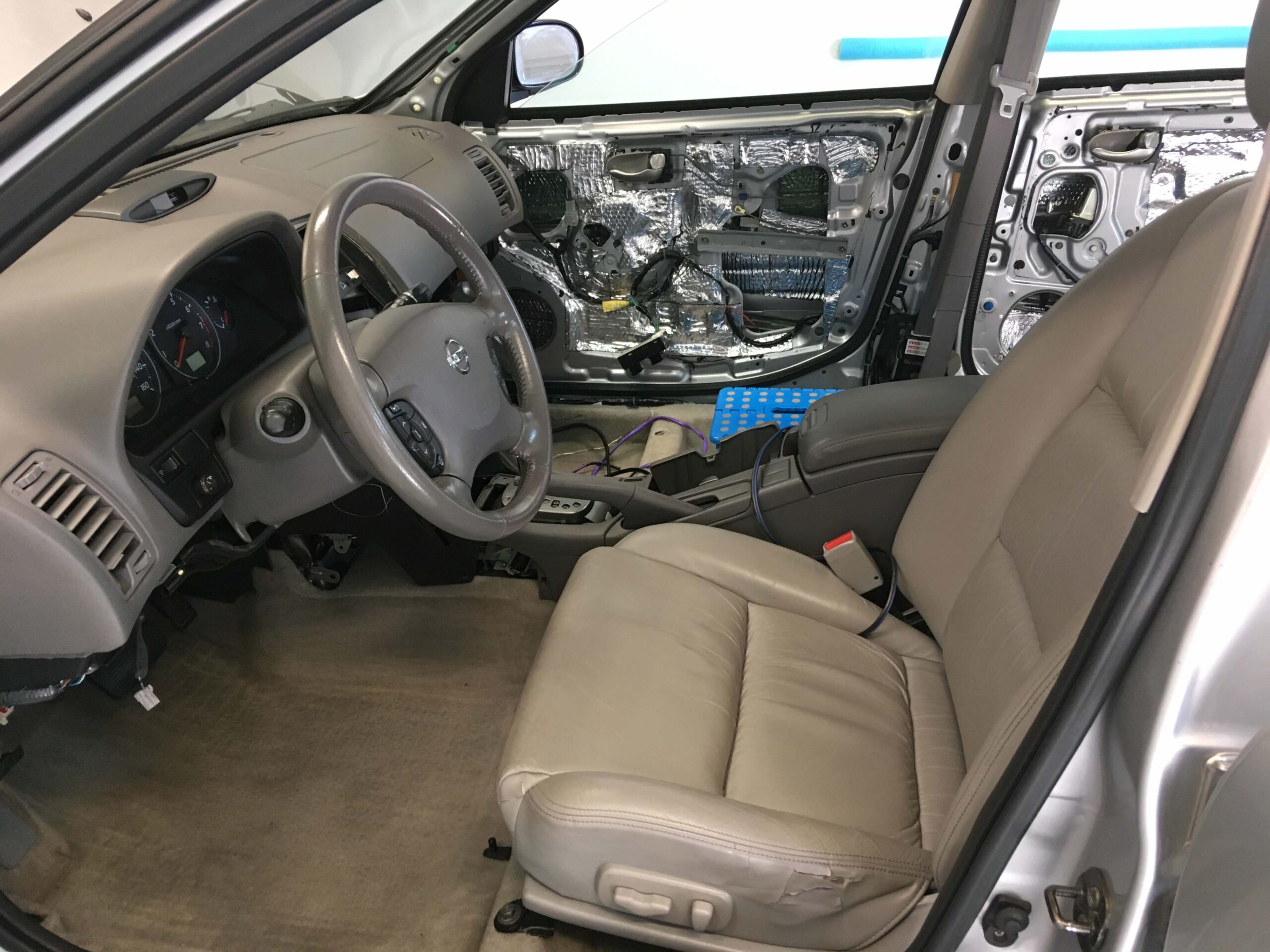
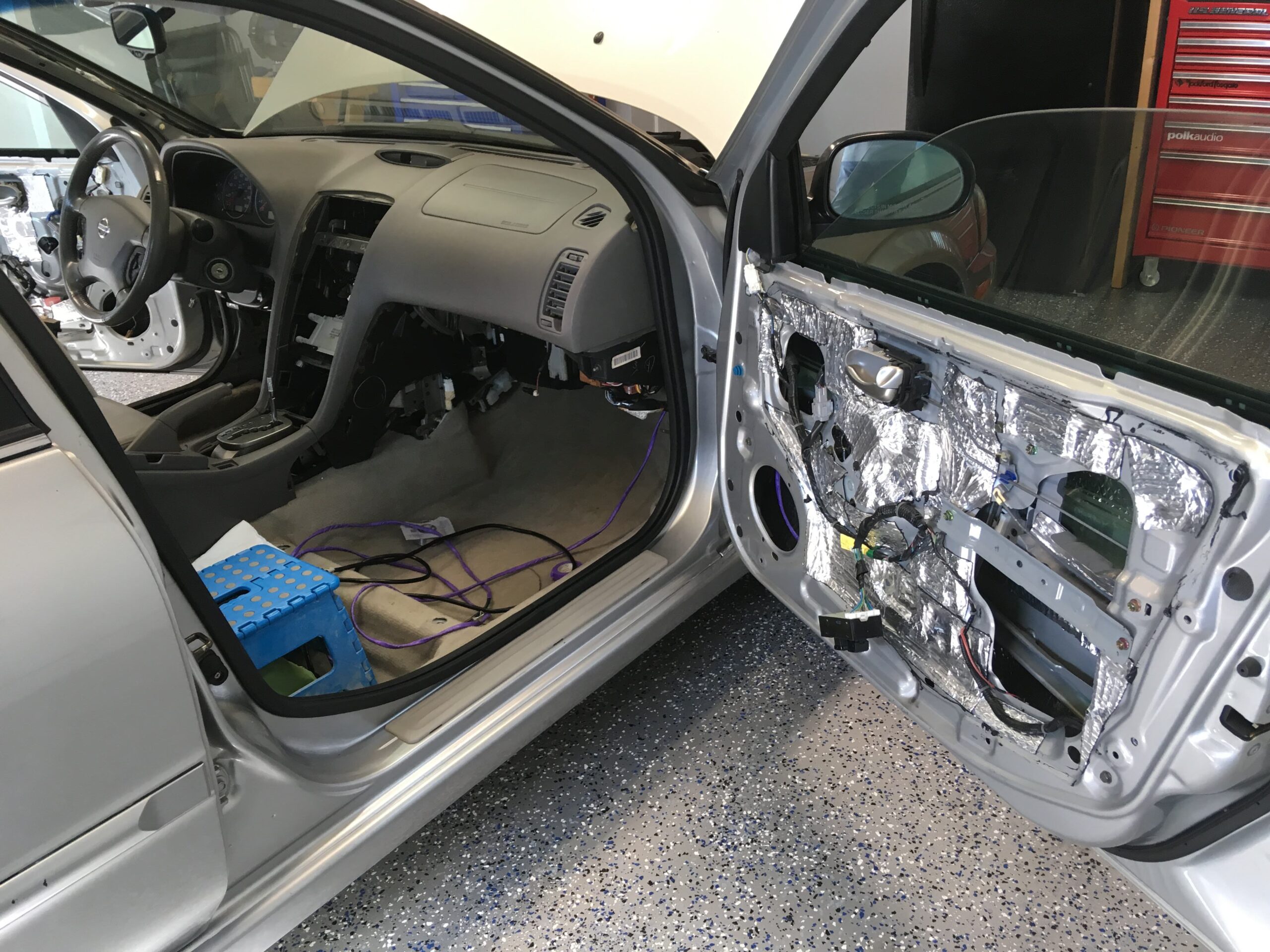
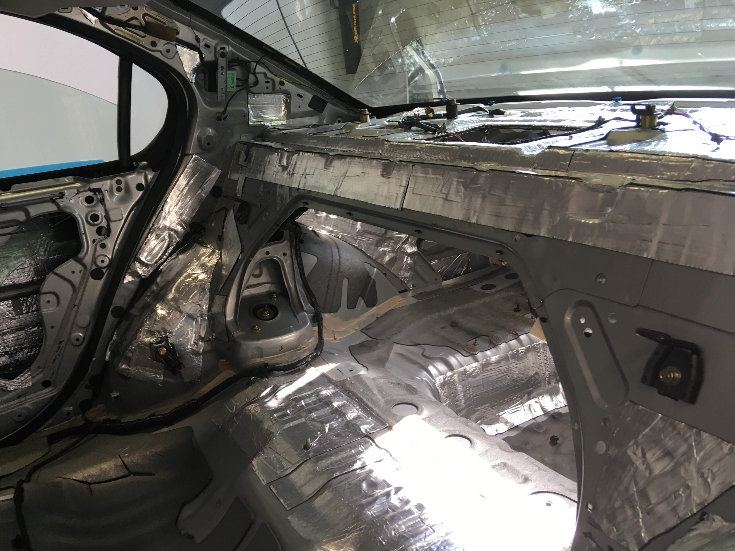
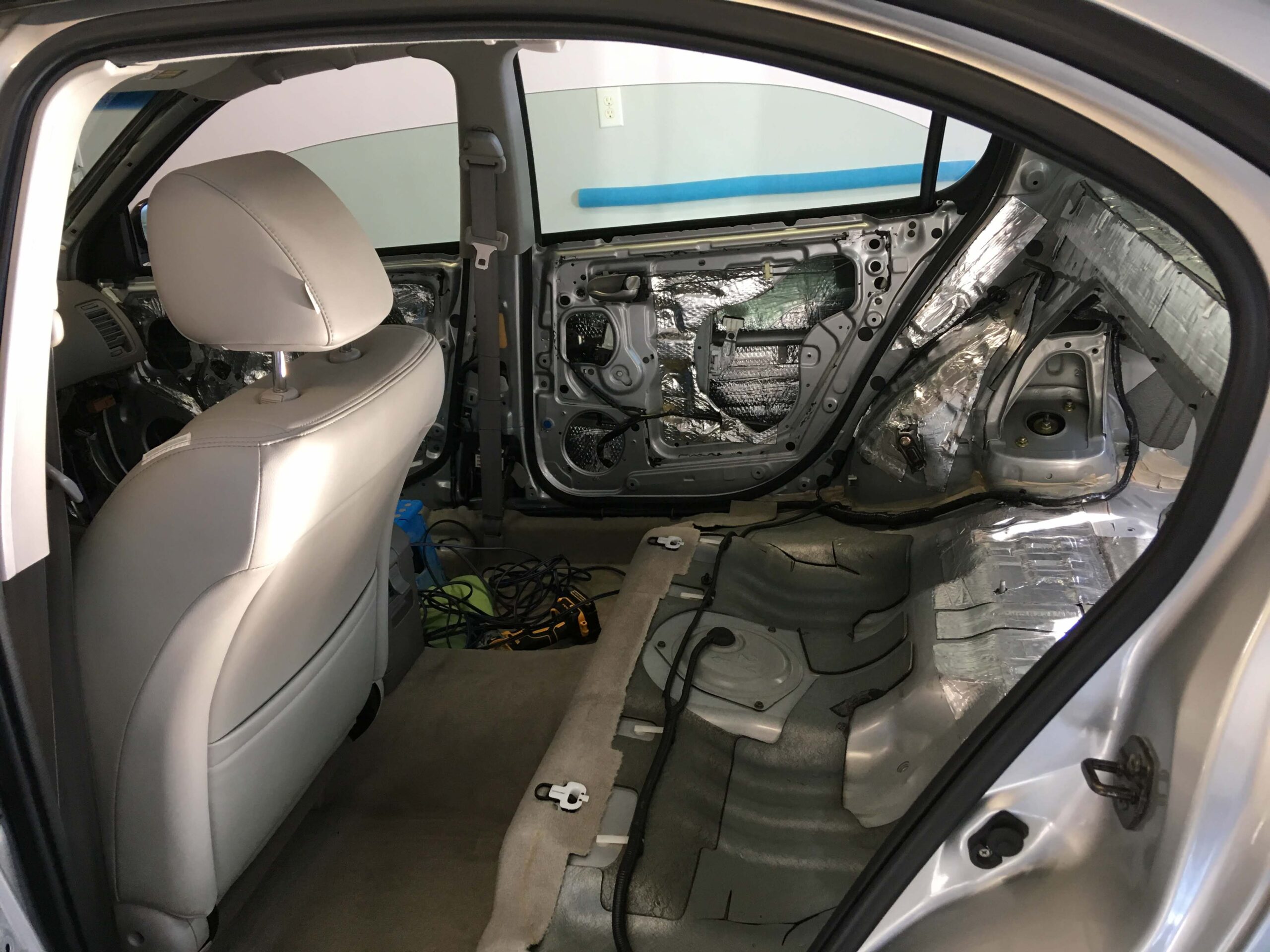
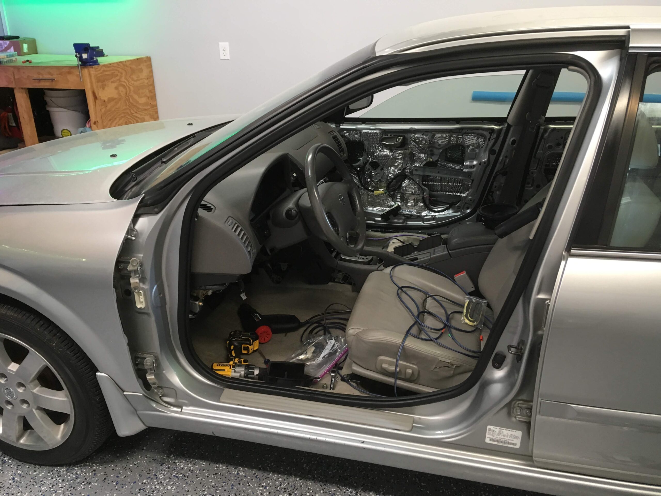
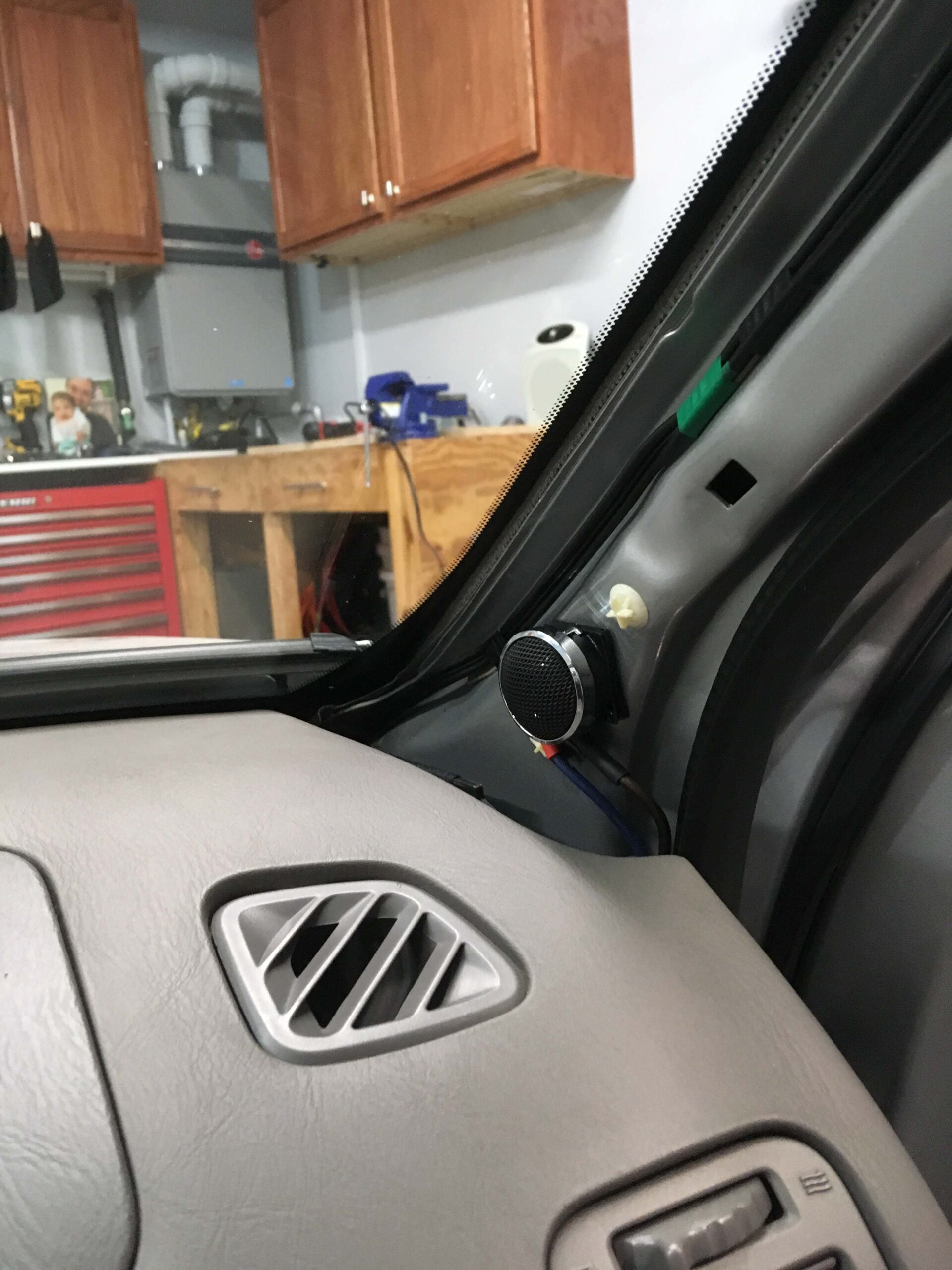
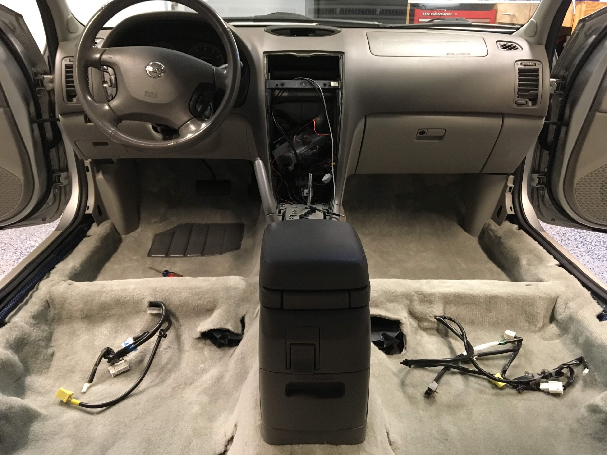
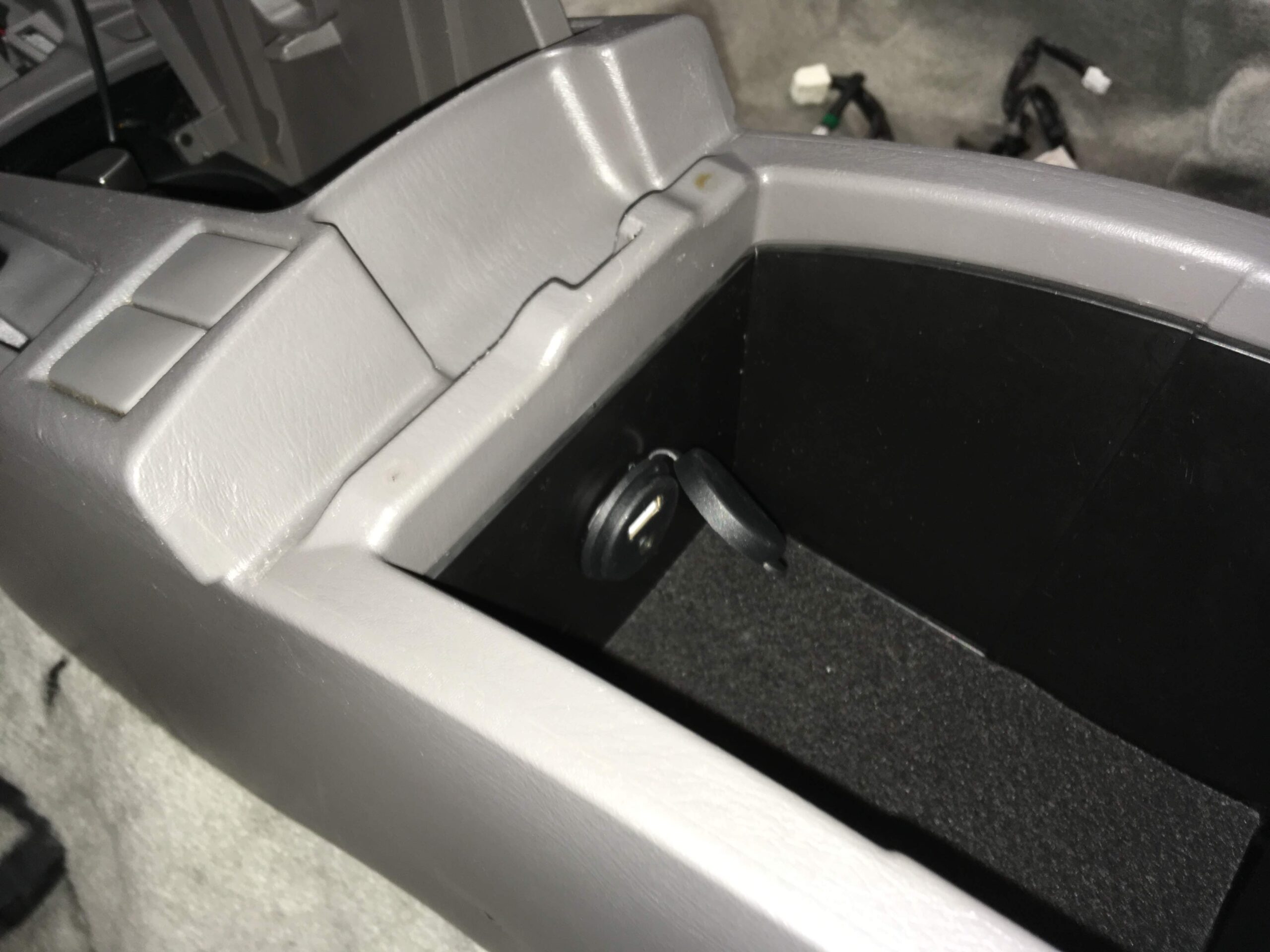
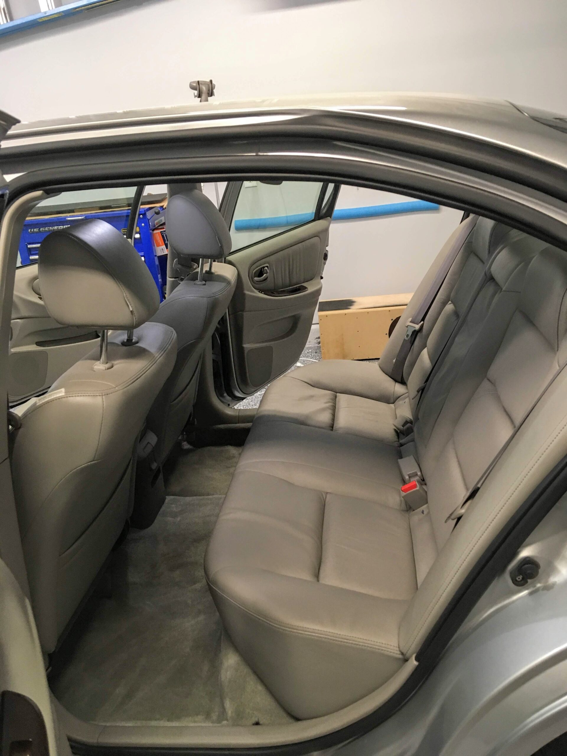
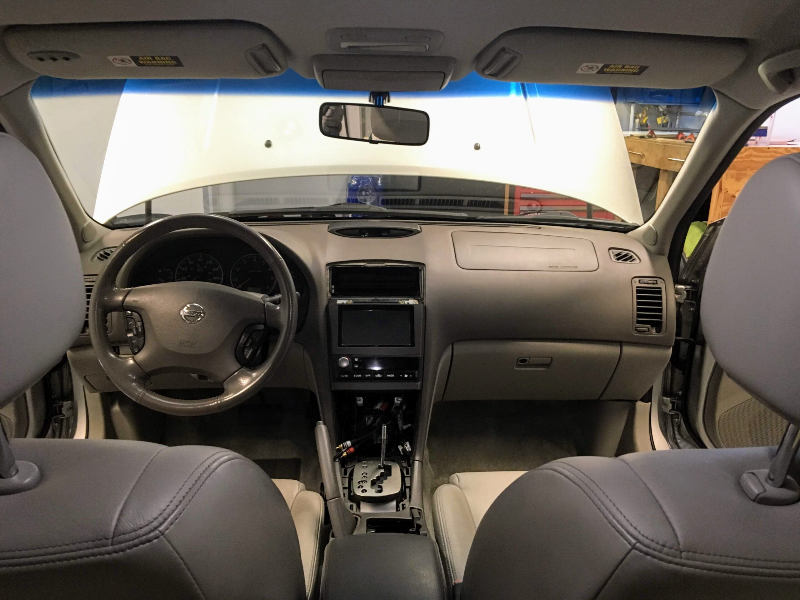
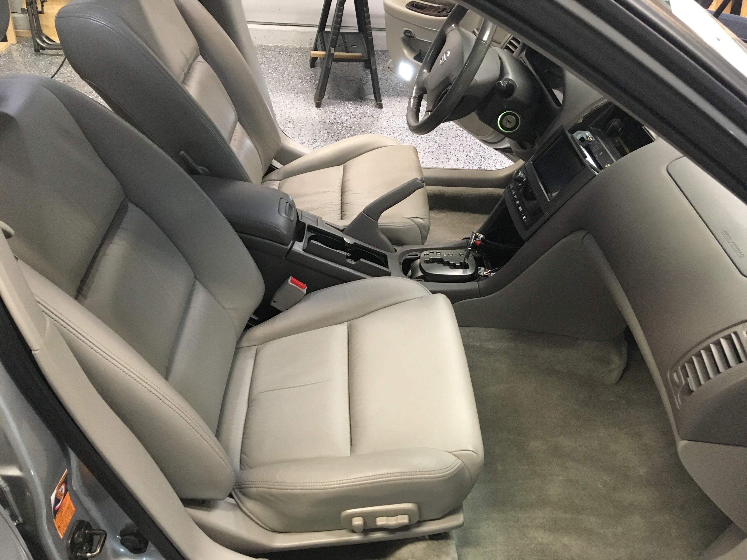
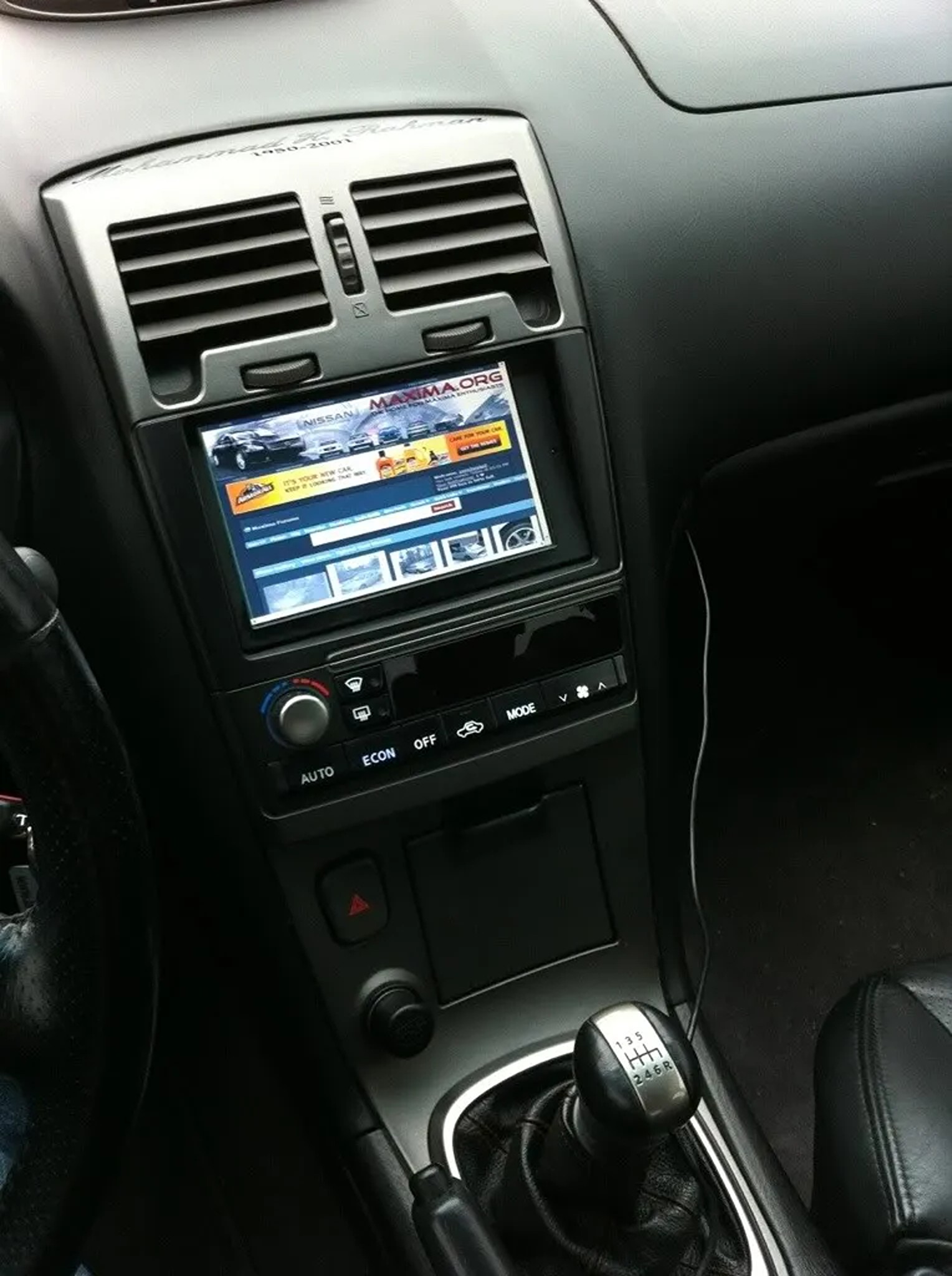
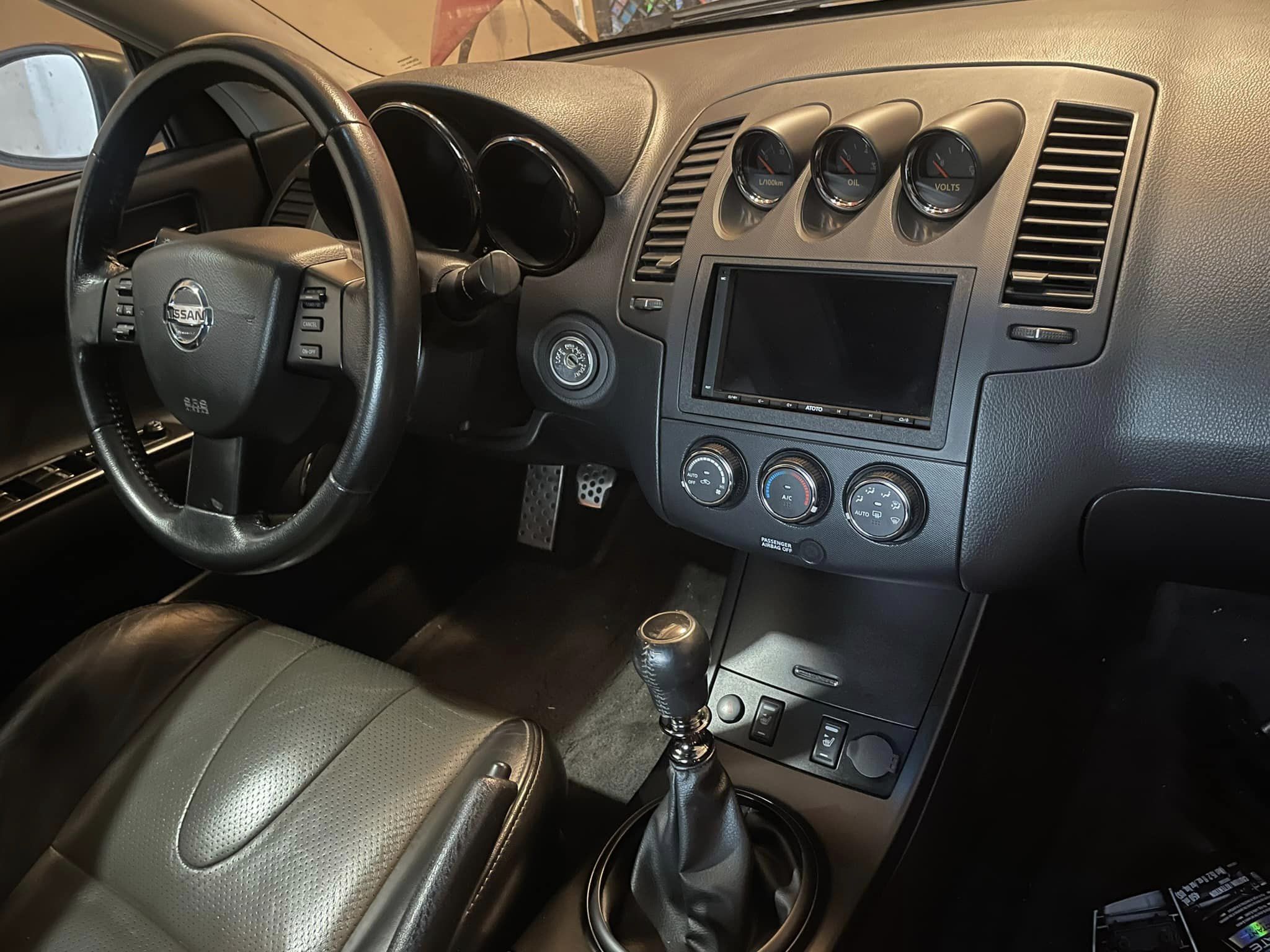
Community Member Credit: YoungMike85
Original Thread: https://maxima.org/forums/5th-generation-maxima-2000-2003/703086-interior-overhaul-stereo-upgrade.html


![]()


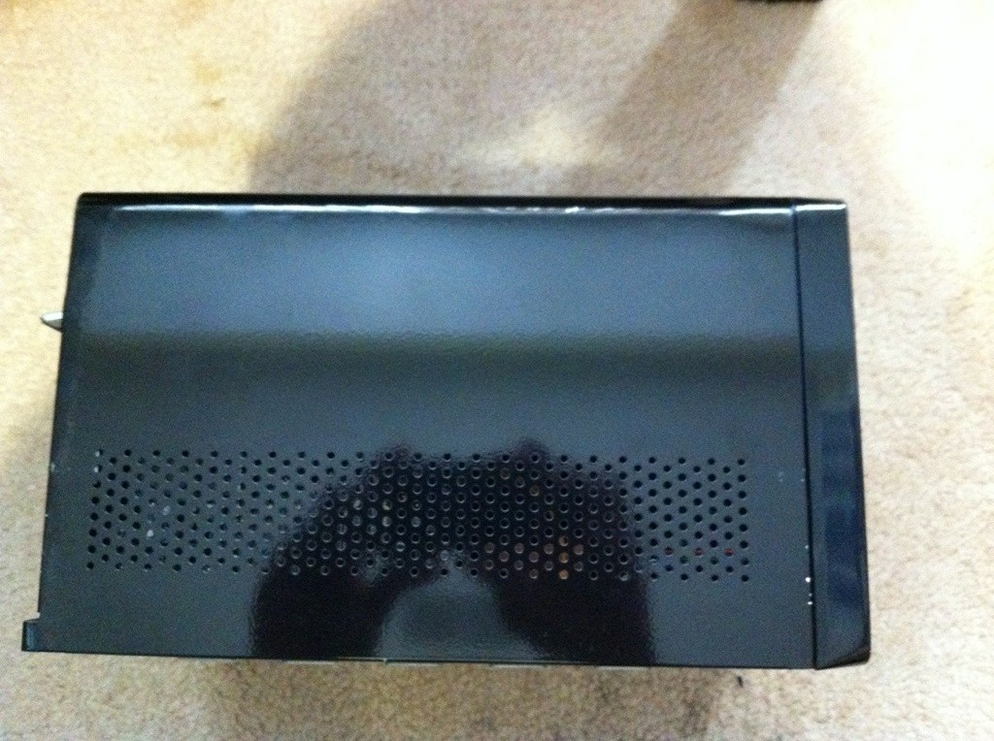
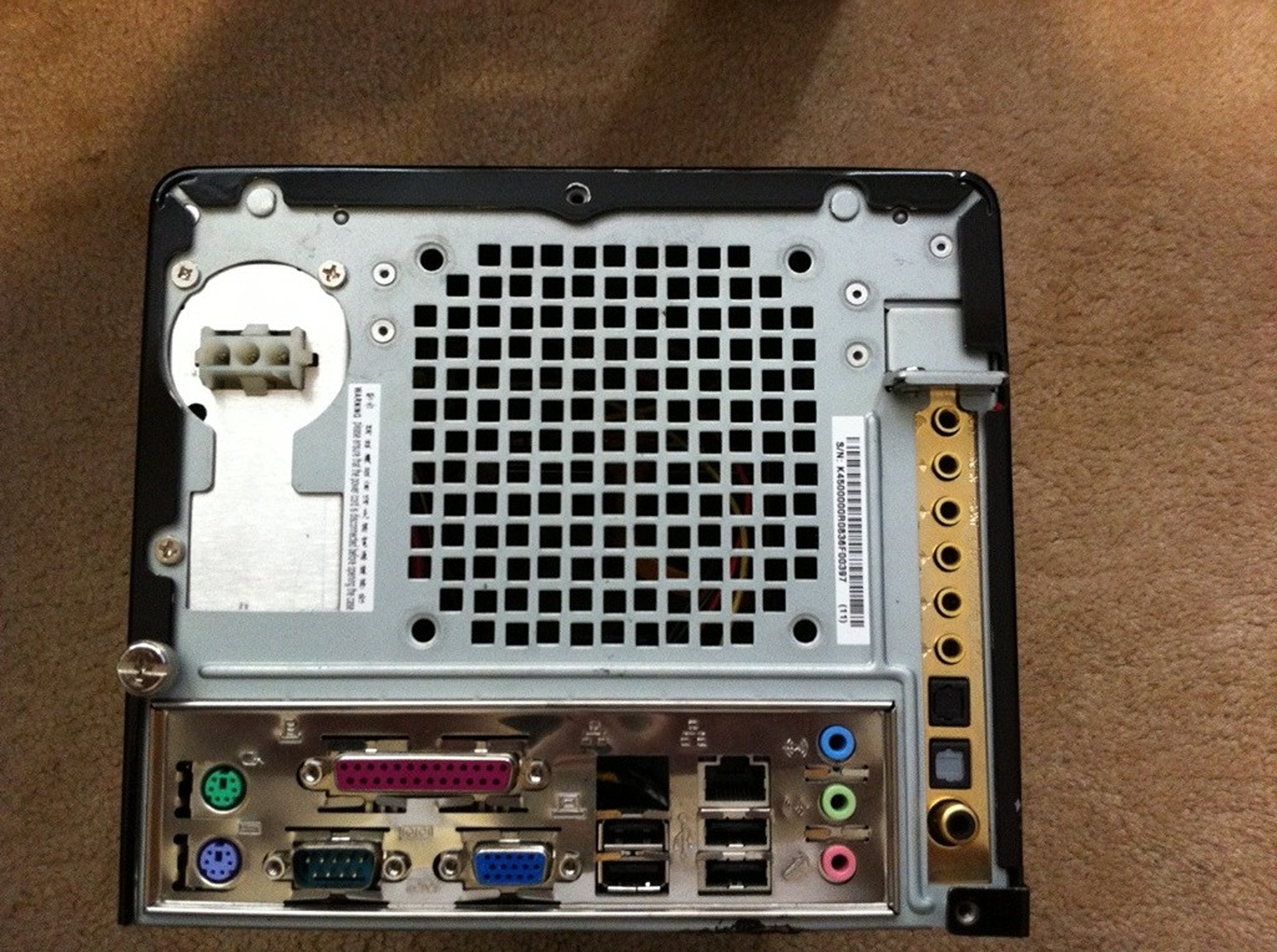
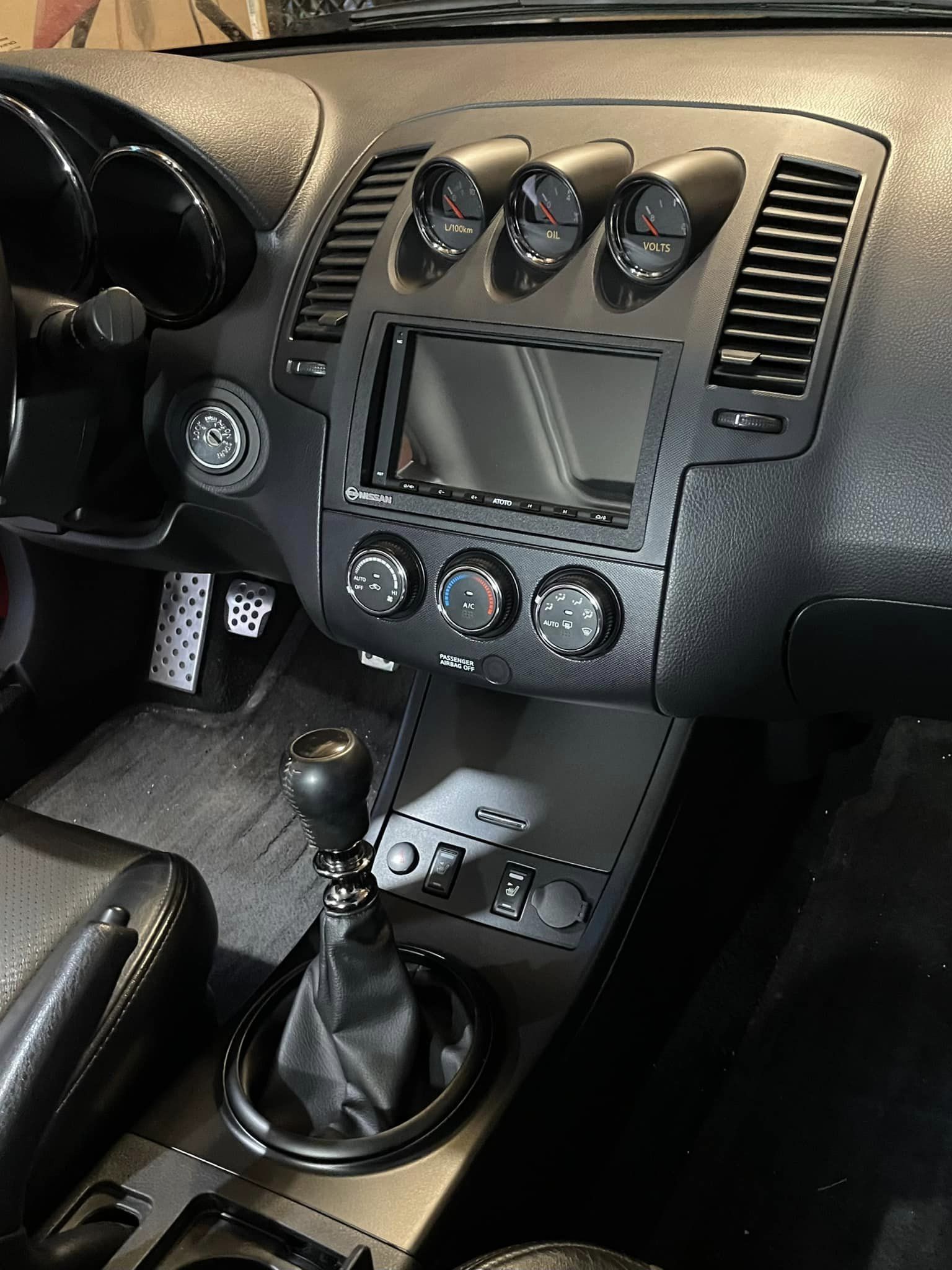
Credit: zero2sixtyZ aka Zeead R.
Specs:
Intel Core 2 Duo 2.2GHz Processor
2 GB RAM
HT Omega Striker 7.1 Sound Card (removable)
OPUS Shuttle 150W PSU + harness + additional molex splitter for powering a screen
Standard AC-DC PSU also included


![]()

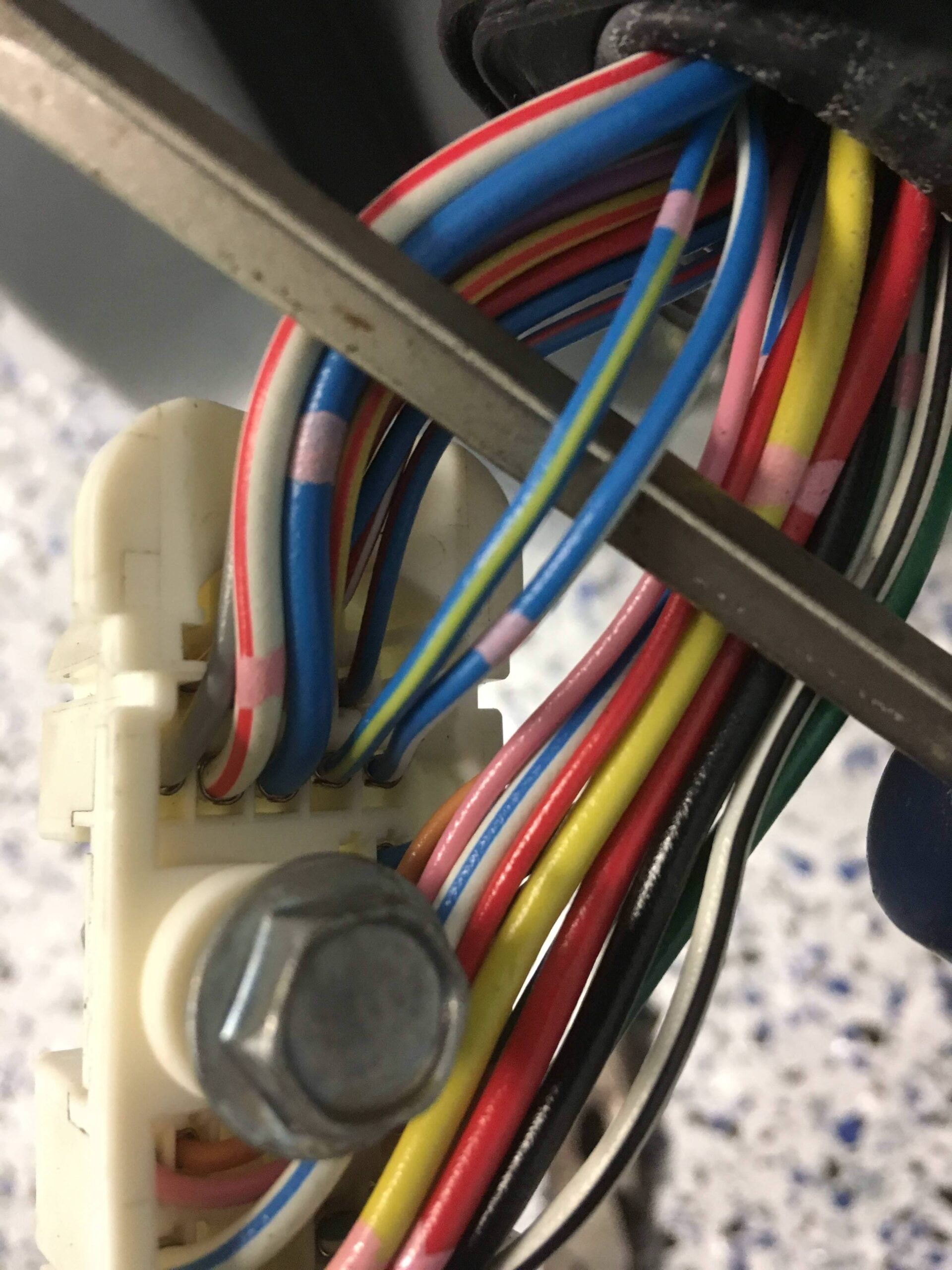
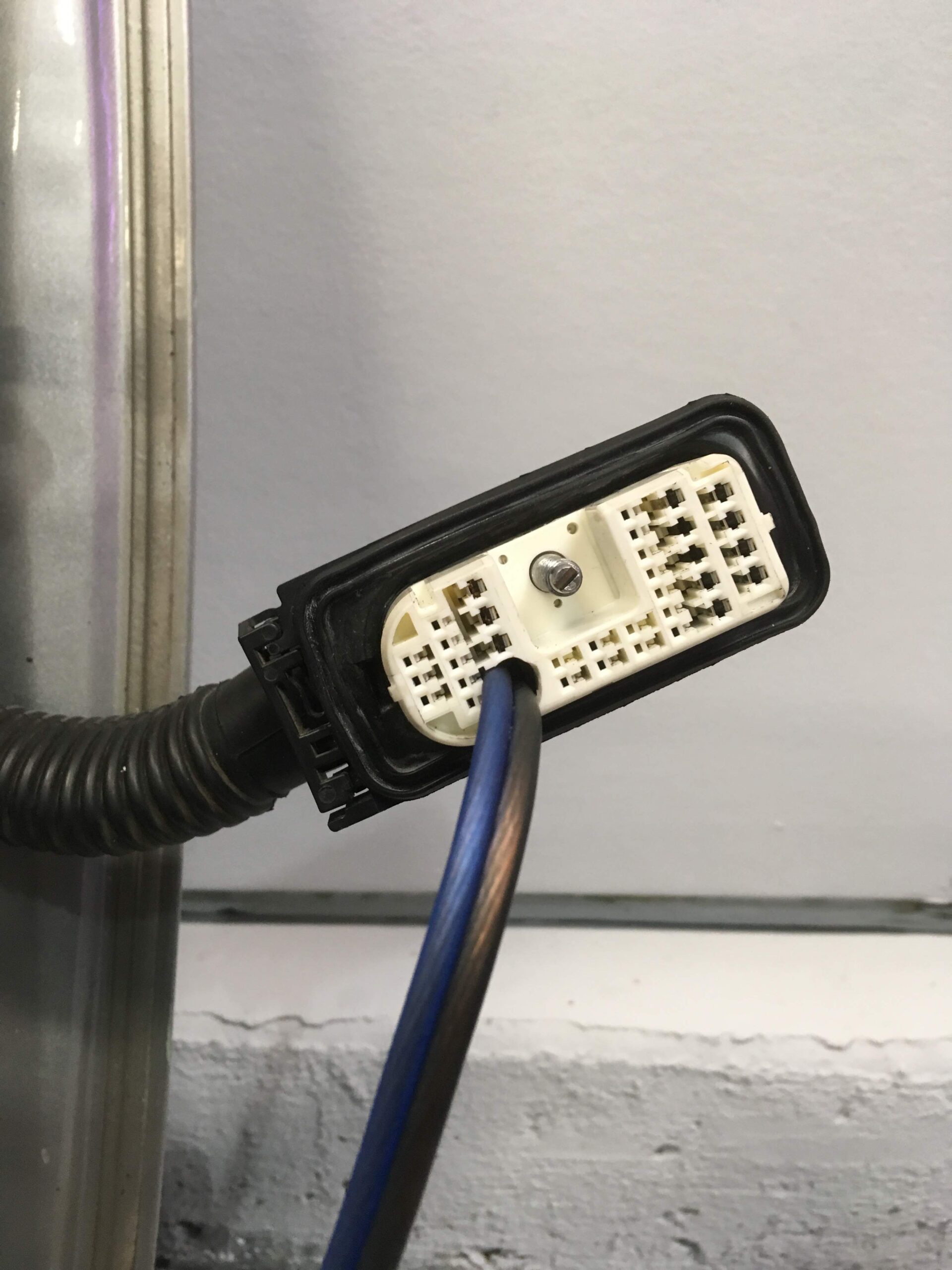
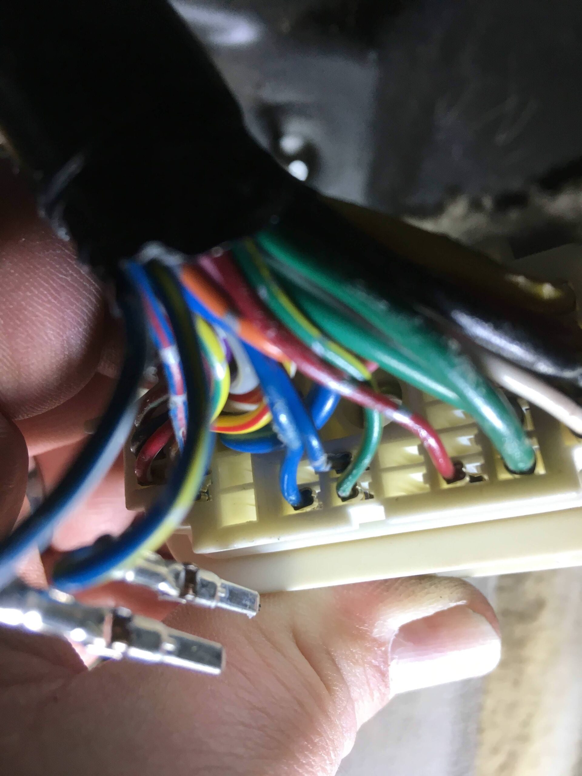
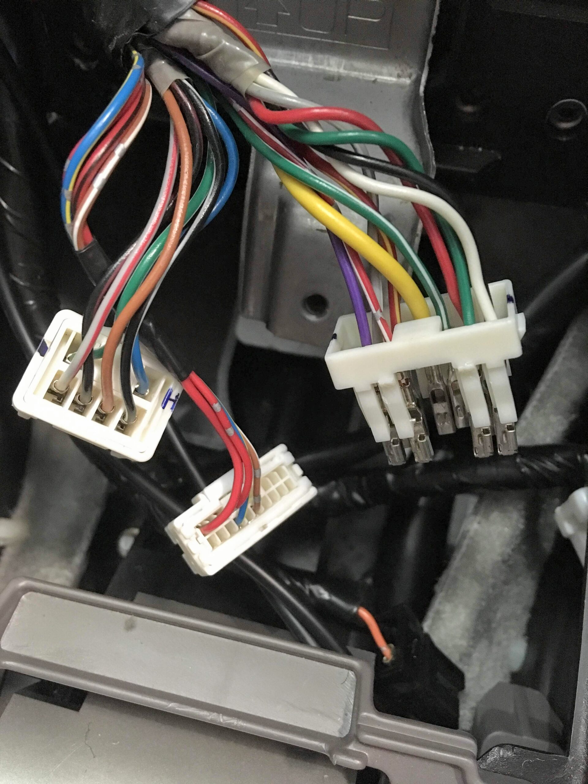
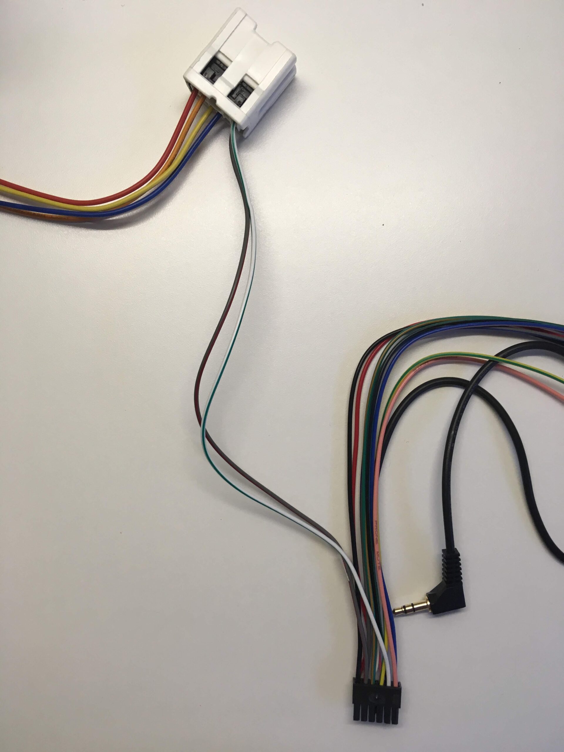
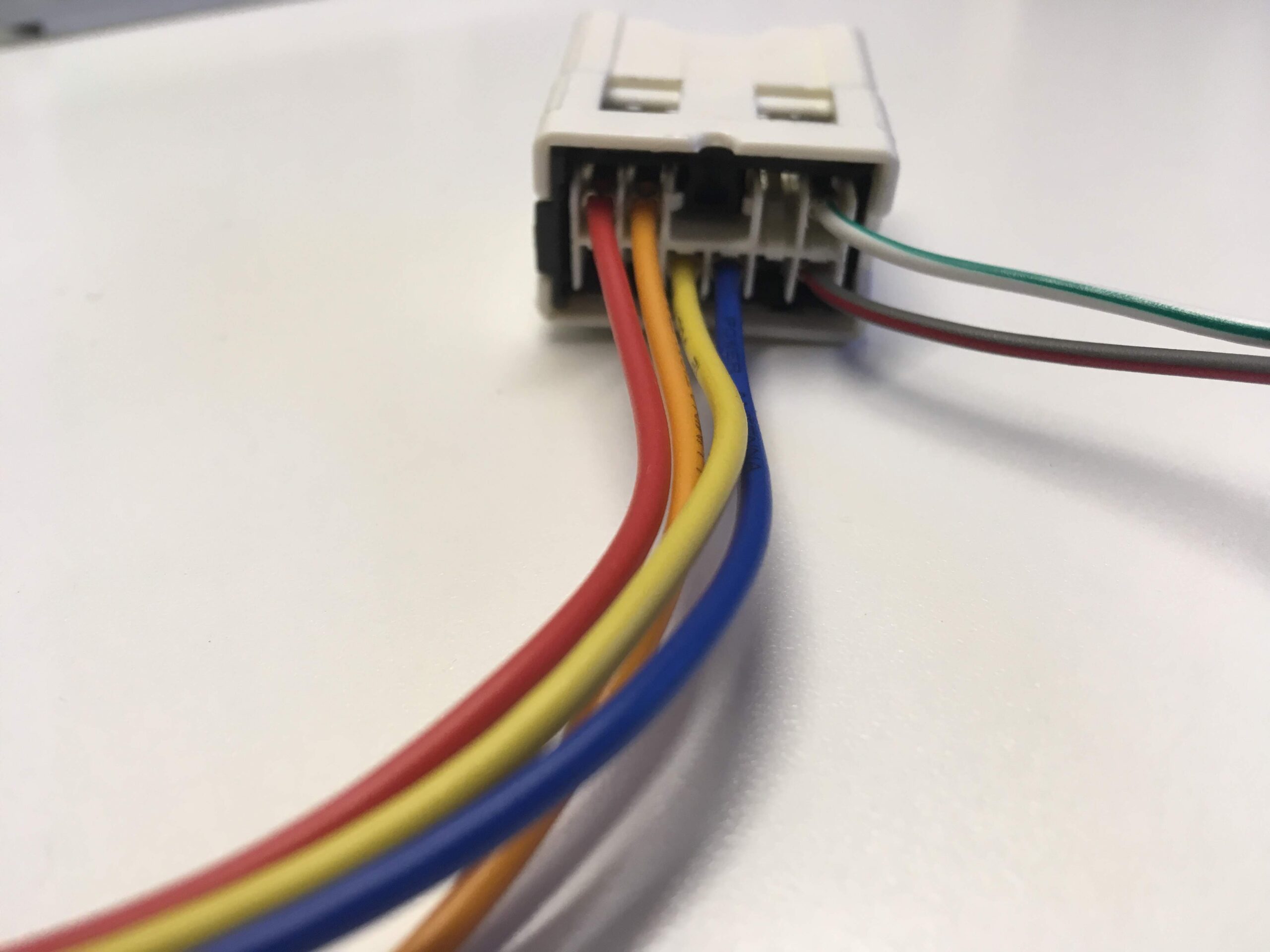
Listed below is the vehicle specific wiring diagram for your car alarm, remote starter or keyless entry installation into your 2002-2003 Nissan Maxima . This information outlines the wires location, color and polarity to help you identify the proper connection spots in the vehicle. Please be sure to test all of your wires with a digital multimeter before making any connections. More information on using a multimeter and testing wires please see our Technical Support Area.
| PART | COLOR | LOCATION |
| 12 VOLT CONSTANT | BLUE (+) | IGNITION SWITCH HARNESS |
| STARTER | BLACK/RED (+) See NOTE *1 | IGNITION SWITCH HARNESS |
| STARTER 2 | BLACK/WHITE (+) See NOTE *1 | IGNITION SWITCH HARNESS |
| IGNITION 1 | BLACK/YELLOW (+) | IGNITION SWITCH HARNESS |
| IGNITION 2 | N/A | |
| IGNITION 3 | N/A | |
| ACCESSORY/HEATER BLOWER 1 | RED (+) | IGNITION SWITCH HARNESS |
| ACCESSORY/HEATER BLOWER 2 | WHITE/BLUE (+) | IGNITION SWITCH HARNESS |
| KEYSENSE | N/A | |
| PARKING LIGHTS ( – ) | LIGHT BLUE (-) | @ HEADLIGHT SWITCH |
| PARKING LIGHTS ( + ) | RED/BLUE (+) | IN DRIVERS KICK PANEL |
| POWER LOCK | ORANGE/BLACK (TYPE B) See NOTE *2 | @ MODULE, IN DRIVERS DOOR |
| POWER UNLOCK | ORANGE/BLUE (TYPE B) See NOTE *2 | @ MODULE, IN DRIVERS DOOR |
| DOOR TRIGGER | See NOTE *3 | @ SECU, See NOTE *4 |
| DOMELIGHT SUPERVISION | LIGHT GREEN (-) | @ SECU, PIN 1, See NOTE *4 |
| TRUNK RELEASE | BLUE (-) | @ SECU, PIN 16, See NOTE *4 |
| SLIDING POWER DOOR | N/A | |
| HORN | GREEN/WHITE(-) | @ STEERING COLUMN HANRESS |
| TACH | WHITE/GREEN | @ WHITE PLUG, BEHIND INSTRUMENT CLUSTER |
| WAIT TO START LIGHT | N/A | |
| BRAKE | RED/GREEN (+) | @ SWITCH ABOVE BRAKE PEDAL |
| FACTORY ALARM DISARM | N/A | |
| ANTI-THEFT | TRANSPONDER ANTI-THEFT SYSTEM, REQUIRES 791 BYPASS and EXTRA IGNITION KEY | TRANSPONDER @ IGNITION SWITCH TUMBLER |
| EXTRA INFORMATION |
| NOTE *1 When Installing a REMOTE STARTER, you MUST use BOTH Starter #1 and Starter #2 wires. Both wires must be connected to the STARTER/CRANKING Output wire from the Remote Starter or the vehcile will NOT Remote Start when the Engine is cold. NOTE *2 TEST THESE WIRES BY TURNING KEY IN DRIVERS DOOR CYLINDER. UNLOCK REQUIRES A DOUBLE PULSE. NOTE *3 LIGHT GREEN(-) FOR DRIVERS SIDE FRONT DOOR, PIN 1. RED/BLUE(-) FOR THE PASSENGER SIDE FRONT, PIN 2. RED/WHITE(-) SAME WIRE FOR BOTH REAR DOORS, PIN 3. WHEN CONNECTING TO AN ALARM SYSTEM, USE ALL 3 DOOR TRIGGER WIRES AND DIODE ISOLATE, SEE DIAGRAM. NOTE *4 THE SECU (Smart Entry Control Unit) IS LOCATED TO THE RIGHT OR TO THE PASSENGER SIDE OF THE STEERING COLUMN. |
![]()


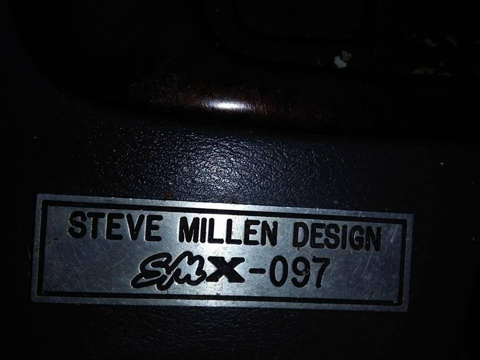
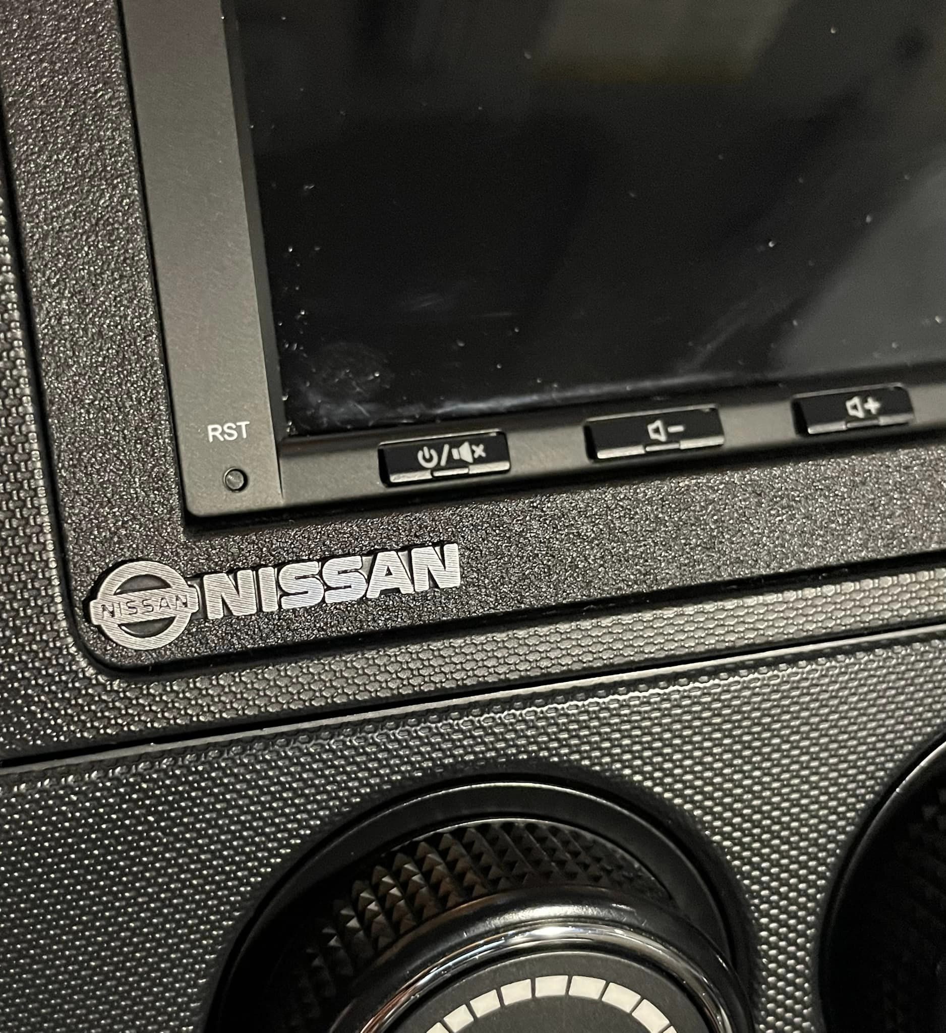
Credit: Kevin N.
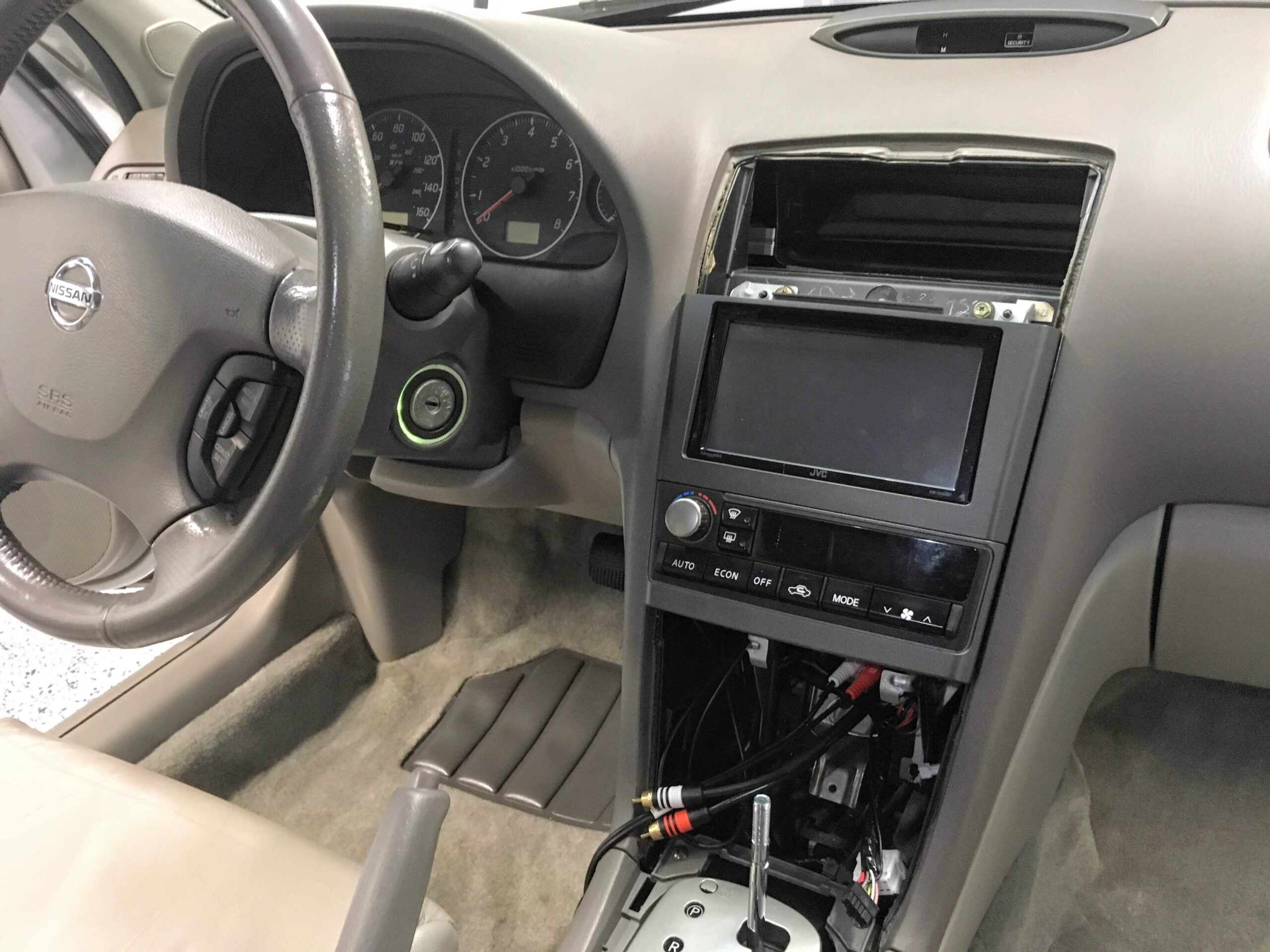
Found these little metal decals on AliExpress and stuck one on the metra dash kit. I think it makes it look more OEMish.
![]()