Category

my4thgen 95-99

Category

Member Credit: choray911

This is a project that has been on my slate for a while, and I’m finally getting around to it. I have seen several people ask what the advantages of stiffer motor mounts are. The answer it simple, the more you reduce the amount the motor moves by rotational force, the more power you put to the pavement, and reduce wheel hop. They do not increase power but allow you to harness the power you already have. The downside is that engine vibration is greatly increased inside the cabin. There are trade-off in every project you take on.

Step 1

Jack up the car and support with jack stands. Remove the lower engine cradle. This can be done by supporting the weight of the motor with your floor jack to slowly lower it down. The tranny and timing cover mounts will support the motor while the lower support is out of the car. I’ve been turbo’d for 5 years, and I cannot recall if removal of the Y pipe is necessary. Use your own judgment.

Step 2

Once the mounts are out of the car, evaluate the condition of your mounts. You will want to remove a lot of the factory material; however, you do not want to change the location of the center bushing. Make sure you have a way to keep it in its factory location. I made sure I had plenty of rubber on both ends to keep it in place during curing.

Step 3

Remove as much factory material as you feel comfortable with. The more Poly you have in there the stronger it will be. To do so, I used an electric drill and several sized drill bits, and a set of needle-nosed pliers. There is considerable metal reinforcement on the inside of the mount, so don’t be too afraid to explore. Just remember to keep the center bushing centered.

Step 4

Cleanliness is next to Godliness! Get a bucket of hot soapy water and scrub away. The cleaner the inside of the mounts are the better the poly will stick to it. Depending on the funkiness, you might want to hit them with some degreaser first. Dawn dishwashing detergent works wonders. If your mom won’t get too upset, put them in the toaster oven at 200 degrees to for an hour or so, to make sure they are good and dry.

Step 5

Seal one side of the motor mount. Trace out the outer boundary of the mount on cardboard and cut it out. Lay the mount on its side and center the circle cardboard piece on the center bushing. Lightly tap the center of the cardboard to make an impression of the center bushing. Cut out the center impression a little small, and then force it onto the center bushing. This will stop the resin from pouring out the bottom. Cover the cardboard piece with aluminum foil, and pull it tight without tearing. Spray some sort of release agent (PAM, Olive oil, WD-40) only on the side that will make contact with the motor mount. Tape it into place using masking tape. Masking tape will not leave a residue like duct tape, but this is your project. Tape the ring securely to the mount. The more tape the better. There will be leaks that show up; this will just keep them at a minimum. Don’t forget to tape around the center hole really well. The resin pours in like warm molasses, and if it has a place to go, it WILL LEAK OUT. Then you have to start over.

Step 6

The Pour. The polyresin I used was Devcon, Flexane 94. It dries the hardest of their line; however, they do have Flexane 60 that is more flexable. It can be picked up at any industrial supply store, like Granger, for around $36. The kit comes with the resin, curing agent, plastic cup to mix it in, and a stir stick. One “kit” will build two mounts with some leftover if you remove a considerable amount of material from the factory mount. Place the mounts on their sides, and make them level. Rolls of duct tape or masking tape work. Combine the resin and activator according to the enclosed directions and stir for a good 7 to 10 minutes. The mixture has a work time of a good ten to fifteen minutes depending on temp and humidity. The warmer it is the faster it cures. You only have one shot at this, so make sure the mounts are ready to be filled. Pour slowly and try to keep from developing bubbles in the mount. Fill one-half full; fill the next one-half full, and then top off the first.

This gives the resin a chance to seep into all the nooks and crannies and allowing the air to escape. If small leaks appear, don’t freak out. The resin will thicken up and stop leaking. If a big leak shows up, get creative, you didn’t follow the directions.

Step 7

The Cure. The mixture will harden so that it can be handled within 30 to 45 minutes. To speed up this time, place them under a heat lamp. I have a torch lamp in my living room that has 3 adjustable lights that work perfectly. Remove the cardboard end and foil. They are hard in 24 hours and reach full stiffness within 7 days. If this is a two-day project then you can put them in the oven again at 200 degrees for 24 hours to speed up the cure.

Step 8

Reinstall.

Loading

Community Member Credit: luke95gxe

Tools Needed:

The first thing u wanna do is remove your intake to get some room

Then u need to hook a rubber hose to the bleeder valve on the slave and put the other end in a bottle to catch brake fluid.

Go ahead and open that bleeder 10mm take the cap of the master cylinder reservoir and let it drain out crack the upper bleeder open 12mm to speed up the process.

Then you wanna remove the slave cylinder (2 14mm bolts). You could probably leave it on to remove the old hose from it but it seems easier to remove the whole slave if you have a strut bar remove the driver side (3 14mm nuts) for room.

Once you get that out of the way go ahead and remove the 12mm bolt on the slave to remove the old hose then move up to the master cylinder.

Remove the old hard-line from the master cylinder 10mm. It’s tight right there but I managed it then you can hook the new ss line to the master cylinder mine was an 11mm nut yours may differ.

Then route the line where u want it and install the other end to the slave cylinder.

Once u do that you can do one of two things leave the old clutch lines on the car or remove them. I took mine out looks cleaner. I took some pics but remove them from the car is pretty easy here are the pics disconnect this

Remove the 2 10mm bolts here

There is a junction box right under the brake master cylinder where all this junk meets just unbolt and remove.

Now you need to bleed the line once that’s done enjoy a clutch line u shouldn’t need to replace.

Now let me say this I can deff feel a difference. wife drove it and says that the clutch pedal feels a lot tighter and more responsive best 25 bucks I spent. I recommend this mod to anyone with a 5 speed.

Loading

Owner: TheArtist

Year: 1995
Model: Maxima
Color: Blue
Trim: SE
Engine: VQ35DE
Transmission: 6-Speed Manual

“I have owned this car since 2005 and it has treated me very well. Everything that has ever been done to the car was strictly done be me and me alone. I put a lot of heart and passion into making my maxima different from all the others. It might not be crazy performance wise or have the suspension like others but it suits who I am and what I want from my car. This whole journey has been all about being different in a way that will inspire others to step out of our bubble and dream big. “

Mod List:

ENGINE/PERFORMANCE:

  • ’05 VQ35DE swap
  • Injen intake
  • 3.0 ECU, timing, UD pulley, MAF
  • NWP block off butterfly plate
  • Painted valve covers Pearl White
  • Apex’I Muffler
  • Walbro 255fp
  • Random FPR+Gauge

DRIVETRAIN:

  • 6 speed swap ’05 tranny
  • Exedy Clutch Stage II
  • Custom ’05 Flywheel to match the 3.0 timing ring
  • SS Clutch Line

Brakes:

  • TT 300zx Aluminum 4Piston Front Calipers
  • HPS Hawk Pads
  • BlehmCo, 300zx to maxima brake conversion brackets
  • 300zx to Maxima conversion SS Brake lines
  • ’04 Maxima cross drilled/slotted rotors
  • All brakes painted a custom mixed gold

Suspension:

  • KYB AGX struts
  • Tein S-Tech springs

Wheels:

  • Rota P45R 18×9.5″ +30
  • Falken tires 245/45/18
  • Wheels painted pearl white

Exterior:

  • House of color Burple paint, color shift pearl, red to gold to green.
  • Pearl white wheels, gold brakes
  • R34 one piece headlights, white and black mixture to match the wheels and lip kit
  • Retro with TL projectors DR2 bulbs 6000K
  • Clear turning/running lights
  • 6000K fog lights
  • IonicDynamics lip kit flat black
  • Ebay clear and red tail lights gutted, smoked, put back together
  • M3 lip
  • De badged trunk
  • White LED license plate bulbs

Interior:

  • Carbon Fiber arm rest, door sills holding tweeters, and gauge bezel
  • Full black interior swap, from headliner down to the floor
  • I30 leather seats front and rear
  • Custom painted pearl white seat belt push buttons and window switches
  • 3M white CF vinyl on center console area
  • White LED interior lights throughout the entire vehicle
  • Custom maxima UV/black light door steps that light up when door is open

Audio:

  • Pioneer flip out head unit
  • Pioneer speakers throughout
  • Added Pioneer tweeters to door sail
  • Infiniti 10” sub
  • Kenwood amp

Loading

Community Member Credit: i30ds

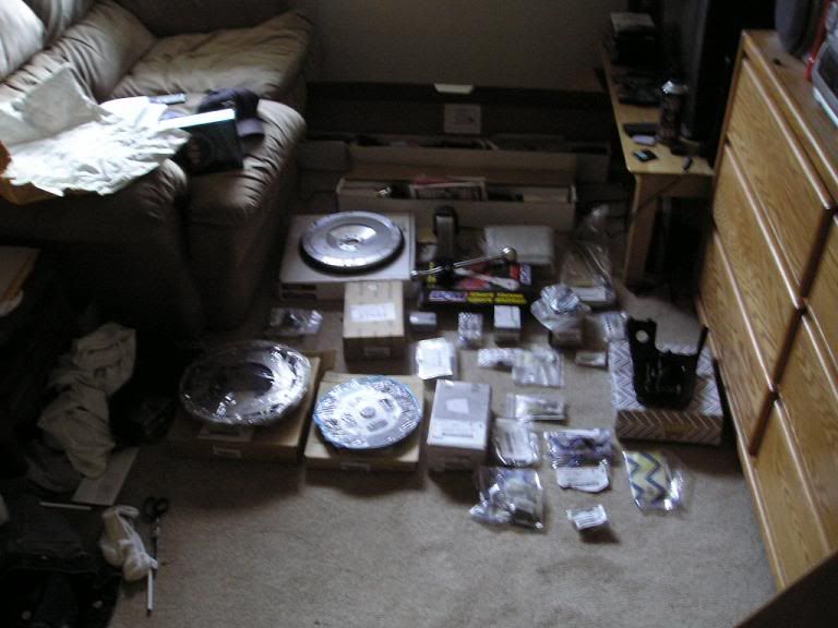
I took my time and saved a bunch of cash for a host goodies. Best ball park guess (includes shipping) $3500…
This included a lot of new stuff:

Just about the only thing that were used are the shift and control rods, the clutch and brake pedals, and a couple of the hard clutch lines. With the rods and pedals, I took them to my grinder and removed all the rust and them repainted them with rust proof stuff.

Parts List:

  • Lsd Manual Tranny- 320B0-40U77
  • Clutch Slave Cylinder- Cant Find Invoice
  • Clutch Master Cylinder- Cant Find Invoice
  • Manual Tranny Motor Mount- 11220-40U12
  • 5th Gen Clutch Disk- 30100-2Y904
  • 5th Gen Clutch Cover- 30210-89F00
  • Manual Flywheel Bolts- 12315-77A00
  • Clutch Cover Bolts- 30223-07S00
  • Shift Support Rod Bolt- 08121-0252F
  • Clutch Cover Bolt Washers- 30240-07S00
  • Slave Cylinder Bolts- 08121-02528
  • Manual Motor Mount Bolts- 01125-03291
  • Breather Tube for Manual Tranny- Cant Find Invoice
  • Shift Rod Support Bushing- 34560-70N00
  • Transaxle Hole Cover Plate Bolt- 74965-0E510
  • Return Spring- 34573-40U00
  • Manual Shifter Trim (Wood W/ Black Boot)-96935-40U10
  • Ae Shift Knob- 32865-4Y910
  • Ae Pedal Covers (Clutch and Brake Are the Same)- 46431-AB000

First, I removed the seat (only 4 bolts and a couple of connectors), the steering wheel trim, lower dash panel and the metal bracket behind it, the trim around the gauge cluster and pulled the cluster out (but left it connected), and the 4 nuts that support the steering wheel up. I used a jsck stand to support the wheel so that way it would not be just hanging there bottoming out and possibly causing some damge.

Now with all this stuff out of the way I now had enough room to remove the auto brake pedal/bracket. In order to do this I also had to remove the left steering wheel support bracket which is held in place by 3 nuts, and 2 of them require access through the cluster area which is why I removed it. With that out of the way, the brake pedal was only 4 nuts and a couple of connectors (but the 4 nuts can be a b!tch to get at).

I now had enough room to drill through the fire wall for the clutch master cylinder. I bought a right angle adapter for $35 from home depot (drilling in this tight of an area would have been IMPOSSIBLE with out it and I dont know how the other guys could have done it).

I also bought a STEP bit for $10 from home depot (I dont know why the hal write up called it a ‘tree’ bit). If you are thinking about just using a 3/8 bit (the size of the two holes for the studs that come from the clutch pedal bracket through the fire wall), forget it!! I tried to do this but the bit is too long, even with the right angle adapter. You need the step bit which gets progressively bigger as you go down the bit.

For the hole for the mater cylinder I used a 1-1/2 hole saw bit (once again, I dont know why the hal called a cylinder bit). This is the exact size for the master cylinder.

With all this, I drilled my holes (sorry I for got to take pics), and mounted the cluch pedal and the master cylinder. I know the master looks off center, but the holes lined up perfectly from the inside and the pedal bracket mounted up to the other factory bolt holes (that were previously unused) perfectly as well. This makes me think that the insulation in the engine bay is what is off (for some reason or another). It is moot point regardless.

Finally, I put the brake pedal in a long with the left steering wheel support bracket (I dont know why the hal threw his away, with out it your steering wheel is only half way supported), and put everything back together. The clutch pedal is NOT attached to the master cylinder in these pics (I have a new one on order), and this is why the clutch pedal sticks out more than it should.

Fidanza flywheel, 5th gen clutch, clutch master cylinder, clutch slave cylinder, ss clutch line from the GD, Raxles axles, AE clutch/brake/gas pedals, B&M short throw shifter, AE shift knob, shift support rod mount, manual tranny mount, plate bolt with transaxle hole cover, shift console trim piece with boot, a lot of misc. bolts and nuts, and of course a brand new LSD 5spd tranny.

Here is all the auto junk I ripped outta there. This includes all the little bullsh!t cables and brackets. I even removed the key interlock cable completely instead of just taping it into position like Hal did in his write up.

This was the only connector I ended up having to cut. It is the connector that went to the auto shift lever. I couldnt get it undone because the prvious owner had spilt soda down in there and it solidified the connector into one sh!t mess. I had to cut it.

While I was in there, I decided to replace the rear main… As you can see I had the slightest seep.

I rvt’d the hell outta the thing so it should not be a problem for a really long time…

Here is the signal plate on the auto drive plate. As you can see, the signal plate is not even shaped right to work with a manual flywheel. Not to mention it is riveted on. This delayed my project as I had to buy a used flywheel, so I could get the signal plate off of it for my Fidanza.

Here is the Fidanza with the signal plate on it.

Gotta love how there is already a factory hole… Only if Nissan would have done this for the firewall.

Here are the shift rods… Sorry this was the best pic I could get, because there is not a lot of room under the car.

Here is the car with everything ripped out.

Here are pics of the pedal install. I did this back in May while I collected more parts. I just continued to drive around auto with manual pedals.

Here is the tranny adaptor for my 3 ton jack. This thing is great. It gives plenty of room to rest the tranny on and it has slots so you can strap it down. It also can pivot and turn so you can mount the tranny with ease… Best $40 Ive spent.

Here is the Fidanza flywheel mounted.

Here is the 5th gen clutch.

Here are the Raxles axles. These things are top notch… The best looking axles I have ever seen. There even filled with amsoil grease.

Here is the B&M STS topped of with an AE shift knob. The look is proper… The way the shifter should have come from the fatory, instead of the ugly @ss flagpole.

Here is a shot of the ss clutch line.

WOW… Look at all the extra room now that the auto is gone.

Ahh… Finally back together again!

Loading

Community Member Credit: Ben Garner

The ECU monitors the transmission-mounted speed sensor to determine vehicle speed. When the vehicle speed limit is reached, the ECU cuts the fuel flow to the engine to slow the car. Ok, in no way do I condone breaking any laws. I figured out how to get rid of the speed limiter on the 4thgen with automatic transmission. This also works on 5thgen Maxima with automatic transmission. 

The signal path for the vehicle speed sensor is as follows:

  • Sensor to Speedometer
  • Speedometer to ECU & Cruise Control

If the signal is interrupted at the actual connection to the ECU, speedometer, odometer, and cruise control functions are preserved. The ECU does not receive a vehicle speed signal, therefore it will not limit the vehicle speed. This modification is easy. But beware, it does include modification of the factory ECU wiring harness…not for the inexperienced.

Tools and Supplies Needed:

  • Socket Wrench
  • Socket Wrench Extension
  • 12mm Socket
  • Crimp Tool

Disconnect the negative battery terminal

Remove ECU cover from passenger side footwell.

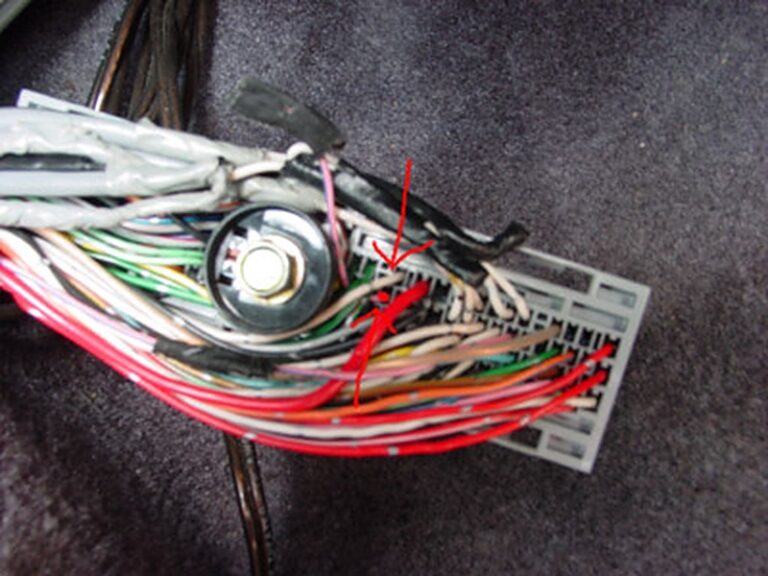
Loosen bolt in the center of the main ECU connector using your 12 mm Socket / Socket Wrench and Extension.

Unplug the main ECU connector. Remove snap-on plastic cover from ECU connector.

Locate PINK wire with BLUE stripe. (This wire is located on the right half of the connector when plugged in ECU PIN 29)

Cut PINK/BLUE Wire (It is recommended that you wire this up to a separate switch so you can turn it on/off when needed. Ensure that you do not cut the Fuel Temp Wire as it is also PINK/BLUE)

If you check the codes, you will get P0104 (Vehicle speed sensor fault) and P0504 (A/T control unit fault). To prevent the CEL you can use a switch to switch on/off for the quick burst for going over 120+ MPH. So far there have been no drivability problems associated with this mod.

Reassemble ECU connection and Reconnect negative battery terminal.

Verify the speed limiter/governor is removed by going past your previously limited speed.

Image result for 4thgen maxima speedometer

Disclaimer: This mod is entirely up to you so do this at your own risk. This modification will cause the “check engine” light to illuminate.

Loading

Community Member Credit: ZaxWhite97Max

Recently I swapped trunk lids with one with a spoiler. And to my unpleasant surprise the LED strip on the spoiler did not work. I got on and searched and searched, Looked through the how-to’s and couldn’t find anything. Although someone did mention that the resistors go bad. Some people need this to work to pass inspection, and if you are like me and think that the clear LED strip “replacement” is ugly, nor do you want to shell out 170 bucks to Nissan for a new one, You can do this.

Materials:

A Blow dryer/Heat gun, Soldering Iron, A Razorblade (or something to “pry” the casing off) and a $1.05.

I used a blow dryer because well, I didn’t have a heat gun and this works too. Your best bet is to heat up one side and try to ‘pry’ it open with something like a razorblade, Be careful not to crack it because it does crack pretty easily I noticed, Although I wasn’t too worried about it because when it is on the car you cannot see it, Just be careful to not crack it to bad so that water or something can seep it and destroy it.

I heated up one side and then stuck the razorblade in there and pried it down. I continued heating each part I pried.

After getting it pried down I noticed one of the resistors was pretty badly burnt out. I honestly do not know the resistance of it. I went to my local Radio Shack and picked up a set of resistors for a $1.05, I got 560 watt 1/2 ohm.

You can easily get a lower resistance, but be careful though. I did notice the 560 ohm wasn’t as bright as I wanted it and will be going back tomorrow for something lower. Here is a picture of it put in:

Notice the cut up black casing, Don’t worry to much about it, it should go back together like a puzzle, or atleast mine did. Because of the fact that I want a brighter one I do not have pictures of it on my car. Note that it is a LOT brighter than you think when you put the red reflector over it so don’t judge by just how bright the LEDS look w/o it.
I will get a better picture of it tomorrow. I havn’t sealed it back up yet but make sure to use something that will not let moisture in. But that is the easy part.

Hope this helps out some of you people!

Loading

Community Member Credit: CS_AR

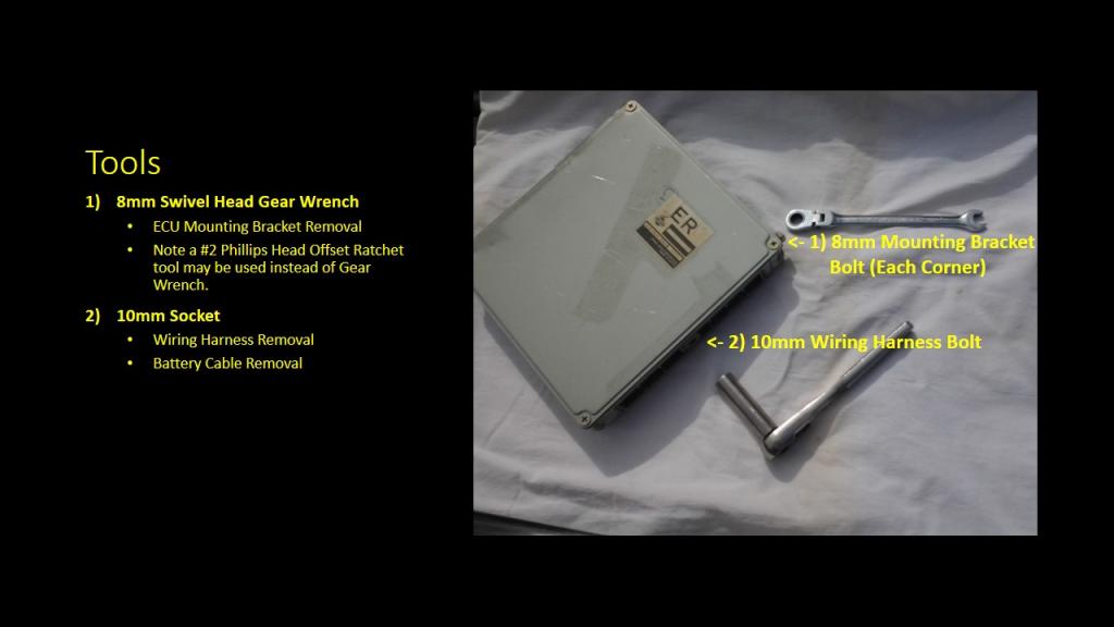
Here’s a slide show I pulled together this morning after I removed the ECU from my 99 Maxima. I read some ECU removal instructions and was able to remove the ECU in about 20 minutes or less.

While I purchased a new Offset Ratchet Screwdriver Tool with a #2 Phillips, once I started the job, I quickly realized my existing 8mm Swivel Head Gear Wrench would stay mounted on the ECU bracket bolts and make the removal go faster.

Name: Slide1_zpsc8bf47fc.jpg Views: 244 Size: 40.4 KB

Step 1 – Disconnect Battery

Name: Slide2_zps5d3b45af.jpg Views: 269 Size: 56.7 KB

Step 2 – Remove ECU Covers

Name: Slide3_zps1d9192e3.jpg Views: 232 Size: 26.6 KB

Step 3 – Remove ECU Wiring Harness

Name: Slide4_zpsa3c113c6.jpg Views: 237 Size: 33.4 KB

Step 4 – Remove Left Side ECU Mounting Bracket Bolts

Name: Slide5_zpsfbc6c657.jpg Views: 296 Size: 44.1 KB

Step 5 – Remove Right Side ECU Mounting Bracket Bolts

Name: Slide6_zps687ba3ce.jpg Views: 307 Size: 48.1 KB

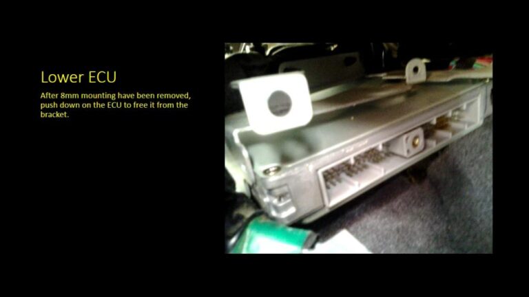
Step 6 – Lower ECU Away From Mounting Bracket

Name: Slide7_zps627d5464.jpg Views: 322 Size: 38.7 KB

Step 7 – Remove ECU

Name: Slide8_zps75b91577.jpg Views: 360 Size: 35.5 KB

Loading