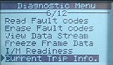
The DTC ODBII trouble code P0335 on a VQ35, found in a Nissan 350Z, Infiniti G35, and many others is a Crank Position Sensor fault, or CKP for short. For this particular write-up we will be showing you How to Service a VQ35 Crank Position Sensor in a Infiniti G35. This sensor is a hall effect-magnetic style sensor that picks up the high and low parts of the flywheel to determine what position the crank is in.
The differences in the teeth of the flywheel provide changes in the voltage feedback given to the PCM from the crank position sensor. The P0335 DTC can be triggered by a few conditions in your VQ35, and needless to say your car will not operate correctly or even start with this DTC.
Here are the detecting condition of the DTC P0335 error code.
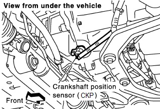
Where is my Crank Position sensor?
Easily the most commonly asked question in our How to Service a VQ35 Crank Position Sensor guide. The VQ35 has it’s Crank Position Sensor ( CKP ) located on the bellhousing of the transmission, and it reads the position of the crank by reading the teeth on the flywheel.
How do I know my crank position sensor is bad?
To test your crank position sensor, first raise the vehicle and locate the crank position sensor and the plug leading to it.
Now that you have located the sensor, unplug the sensor and take a look at the 3 prong weatherproof connector. Don’t forget if you need the how to on servicing your camshaft position sensor, we’ve got you covered.
First you should check the continuity of the wiring by placing the negative terminal on a ground, and then putting the lead to pin 3.
Continuity should exist here, so move on to the next step of our How to Service a VQ35 Crank Position Sensor writeup.
You can test this sensor using a voltmeter with one end connected to a chassis ground and the positive lead going to the 1 pin on the weatherproof connector.
If these 2 wires have continuity your part is more than likely damaged, as the 2nd pin is the signal wire to the PCM.
Why does my car not start?
The crankshaft position sensor is not transmitting any information to the PCM when trying to crank over your motor, without this sensor the PCM will not know how to operate the engine. This is when you will absolutely need our How to Service a VQ35 Crank Position Sensor article to get your car back on the road.
Where is the Crank Position Sensor pin on my VQ ECU?
Pin 13 is the Crankshaft Position Sensor on your VQ PCM, here is a diagram to help you test continuity should you need it.
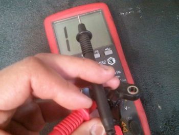
This magnetic crank position sensor can be tested by measuring the resistance between terminal 1-2, terminal 1-3, and terminal 2 and 3.
All 3 of these combinations must measure resistance at 0 Ω or ∞, if your measurements are outside of this reading your sensor must be replaced.
Once you have the unit replaced, plug in your favorite ODDII scanner and clear the code P0335 and you are ready to rock and roll!
You have now serviced your VQ35 crank position sensor and saved yourself a lot of money in dealer labor.
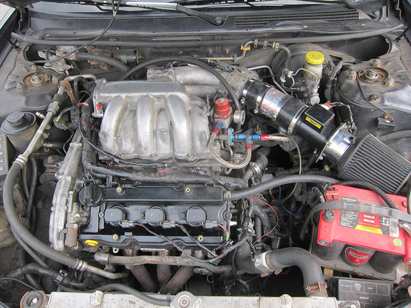
I went to the “Dyno Day” at Dyno Extreme on Sunday, 03-02-08 in Stanton CA (near Knott’s Berry Farm in Buena Park) with James / The Wizard. Well, I got my highest horsepower to date! 322.76 HP and 307.82 TQ.
Last year I was around 240. So, with an 80+ HP increase, I’m quite stoked, to say the least. A HUGE thanks goes out to Jimbo “The Wizard” Ozouf for helping me crank out 3 pretty big mods in just a week before the dyno.
Total (power) mods and variables are as follows:
Un-tuned
Unless I say otherwise below, I have all OEM parts and the “stock” parts that come with the Stillen SC kit (yes this means: stock injectors, stock MAF, standard Vortech FMU with 8:1 disc, Bosch bypass valve, stock fuel pump, etc.)
One-step colder NGK platinum plugs gapped to 0.037”
91 Octane gas
13.7 lb 17” rims
12.5 lb 12.2” rotors (stock are 15lb ea.)
Cattman cat-back
LSS test pipe (just for dyno and track days)
Warpspeed Fed Spec aluminum Y-Pipe
Fed Spec. left bank manifold (from Fanaticrock – thanks man!)
(I did a CA spec –> Fed Spec left exhaust bank manifold conversion which eliminated the huge left bank pre-cat. I installed a Cattman O2 simulator for the two downstream O2 sensors)
Vortech V2 supercharger, freshly re-built
2.87” Vortech SC pulley (see boost/PSI information below)
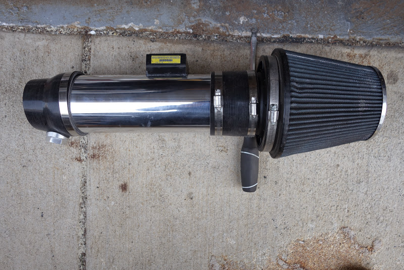
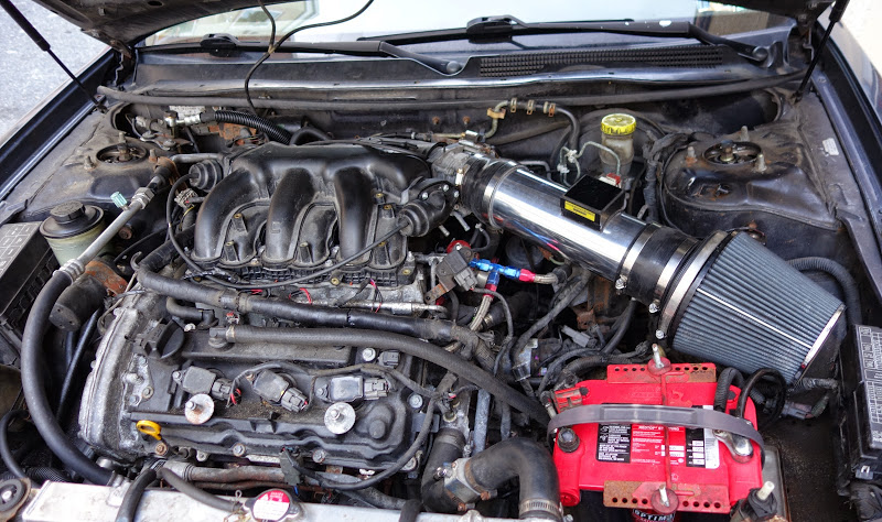
Custom intake piping
A 5”d x 8”l PWR water to air aftercooler (barrel design) with a Bosch water pump, a Jackson Racing front-mount heat exchanger, and a Vortech ice chest/water reservoir.
Thermal insulation to protect the underside of the intake tubing from the exhaust manifold/engine heat.
4th gen. Variable Intake set at 5200 RPMs (installed by The Wizard, the VI master)
Perma-Cool oil cooler (not sure if that results in a power increase or not, but, just in case)
I think that’s it. I hope I am not forgetting anything.
Oh, and my I30 fuzzy A, B and C pillars (good for at least 10 HP )
I have a bad memory but I think the mods that are new this time (322HP) from last time (240HP) are: one-step colder plugs, lighter rotors, Cattman catback, Fed. Spec. conversion, re-built blower (which fixed a chipped impeller blade and inlet oil leak), a few more PSI, larger PWR AC which replaced a smaller JR AC (see explanation below), 4th gen. VI, VLSD tranny with cooler, oil cooler. But I did have my fuzzy pillars last time (otherwise I would have dynoed at 230)!
As far as the boost / PSI level… Well, on the dyno I made maximum boost of 10PSI. However, I always hit 12PSI max on the street. The dyno owner/operator told me this was normal and it’s because the dyno has less of a load than the street. Huh?
I recently replaced my small 3”d x 11”l Jackson Racing (JR) water to air aftercooler (AC) with the PWR AC mentioned above. The PWR is supposed to be more efficient in cooling and result in less boost loss. I now lose 1PSI across the PWR AC where before I lost 2PSI across the JR AC. I also have a dual intake temperature gauge by Autometer. I have one probe upstream of the AC and one downstream. With my JR I would see about a 10 degree difference during idling/cruising and a max delta of 40^ during a full boost run. With the PWR I know see a 15-20^ delta when cruising and a 60^ delta during a full boost run. During the dyno, I added ice to the ice reservoir and saw a max delta of 85^!
Dyno Extreme didn’t hand out dyno graphs that day. So, excuse me for the digital camera photo of my dyno. The owner should be sending out the run files via e-mail shortly so I will post up the dyno when I get it. Also, these are the uncorrected numbers.
I’m really stoked. Two of my dreams were achieved at once: 1.) Break 300HP and 2.) Get a single-digit weight to horsepower ratio (~2900 lb / 322 HP = 9.00 LB/HP!!).
I dug into the cluster to try and figure out why the gauge was off. All the resistors to the fuel level sensor checked out OK but apparently the joints to the board can crack causing intermittent or permanent problems. Re-soldering the joints on the 4 resistors should solve the problem of the fuel gauge reading too high.
The resistors are R4, R64, R124, and R125. They are directly below the cluster part number in the attached picture.
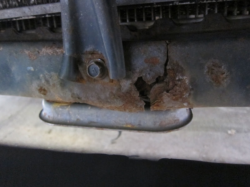
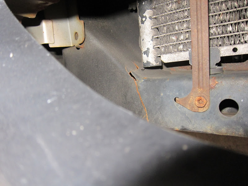
The total time start to finish was 9 hours but my font end was a little mangled. I had to pull out one lower corner, slide hammer and sledge the passenger unibody rail, unkink the drivers side upper rad and unibody rail, and a few other things to get the new part to fit. Ignore the miss alignments. They’re more of an upper rad, fog bucket and bumper support.
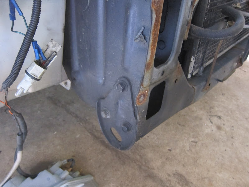
Other new parts: bumper support, support brackets, hood struts, and cross member bolts.
I welded it in either from the back through the holes drilled in the unibody during dismantling or I drilled new holes through the new support to weld it to the unibody. I wouldn’t suggest just bolting it in.
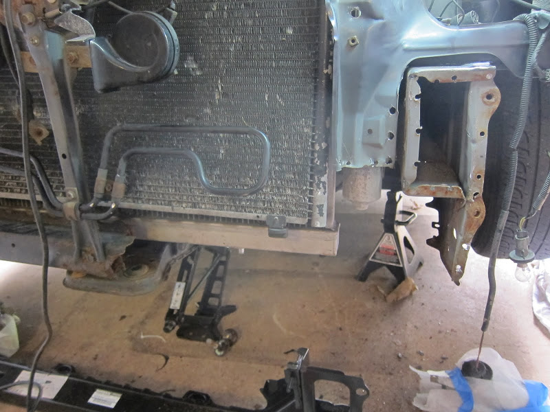
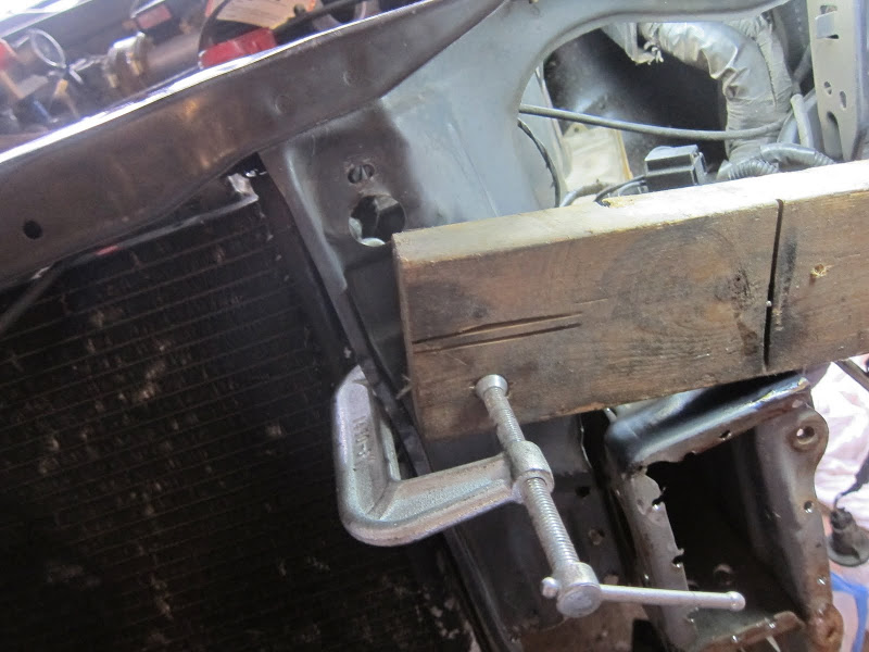
I lined everything up, bolted it in with the tow hooks, spot welded, then took the hooks off to do the last few spot welds on the bottom from the rear. There are 6 spot welds per side that are in the unibody rail and a pita to drill out. I used a die grinder with a long shanked carbide burr to burn through those. This pic shows the 6 inside:
The point of this thread is to give people a heads up on what they’ll have to do to use the 07 Altima motor with the 3.0 timing. If you have the time/skill/money a full 3.5 swap will always out perform a hybrid setup. This is just for people that are lacking any of those and want something better than a typical hybrid swap.
I will not be telling you how to do a hybrid swap. That info is already out there.
Findings:
The upper/lower oil pans, oil pick up tube, and dip stick need to be swapped to a VQ30 or manual trans VQ35 5th/6th gen since the exhaust tunnel isn’t as high and will interfere with the front bank’s exhaust.
Cylinders 5/6 need the exhaust manifold studs swapped diagonally to work with the older gen VQ35’s.
The older crank pulley needs to be swapped on.
There are two knock sensors, one for each bank. I’ll be bolting up a 4th gen sensor to the rear bank.
The grinding for the p/s pulley and flipping of the belt tensioner bolt aren’t necessary since the newer 3.5 covers created those issues and they’re not being used.
The line for the oil cooler has been moved from the thermostat housing to the font coolant tubes and the cooler has gotten larger. The larger cooler will work on both older 3.5 upper oil pans and 3.0s.
You still need to run spacers and drill the intake cams. If you’re wanting to run adapters, typical 3.5 swap adapters will not work. The spacers are for 3.5L swaps with 3.0 timing equipment. They can only be used with drilled intake cams or drilled primary and intake cam gears. These are not adapters.
Here’s where it gets a little interesting.
Researching this swap, the question came up of how the 3.0 timing equipment might alter the timing of the 3.5 cams. I found the exhaust lobe centers of cyls #1&2 on my old 1st gen 3.5 (03 max motor) with 3.0 timing and they were 122* BTDC for the rear bank and 119* for the front. This is about 10 crank degrees retarded from the stock VQ35’s cam numbers (112 BTDC exhaust lobe center line). I used a degree wheel on the crank pulley, the 3.0 outer timing cover arrow as a reference, and a dial indicator riding the lifter bucket to find max lift. IMO, this method is good +/-3 crank degrees but either way the exhaust cams are retarded.
Now for the intakes. The dowel pins actually point up when cyl #1 is TDC’d like they do on a VQ30. But, that dowel pin would make the intake timing 28 crank degrees retarded from where a stock 3.0 would be.
07 Alti intake cam in a jig made from a 3.0 intake cam
Using a dial indicator with snake extension as a pointer to measure how many degrees the cam timing would be off if I used the 07 Alti VQ35 factory dowel pin.
Set as VQ30 timing
Clocked to the factory dowel pin hole
So, 14 cam degrees or 28 crank degrees off.
What I’m doing is drilling through the VQ30 primary/secondary timing gears and cam for the new (longer like other hybrid swaps) dowel pin 180* opposite of the factory gear timing slots so that I’m not just egging out the 07 Alti dowel pin hole. The stock 07 Alti intake cam bolts need to be reused for the intakes too. The VQ30s are too long.
The above cam timing would net:
Intake__Duration: 240º
Exhaust_Duration: 240º
Intake_Opens: 7º BTDC
Intake_Closes: 53º ABDC
Exhaust_Opens: 47º BBDC
Exhaust_Closes: 3º ATDC
Overlap: 10º
Strange the exhaust timing matches up pretty close with a 3.5 Pathfinder. Either way it should be good overall.
I’m going to be using an 09 Maxima upper intake and (converted) throttle body with this swap since both are larger. The p/ns for the lower intake on both cars are the same number. The 07 Alti’s could obviously used if the TB is converted too. Before the engine went back I made sure the 09 Max upper intake bolted up without issue. No problems.
Altima Manifold
Maxima Manifold
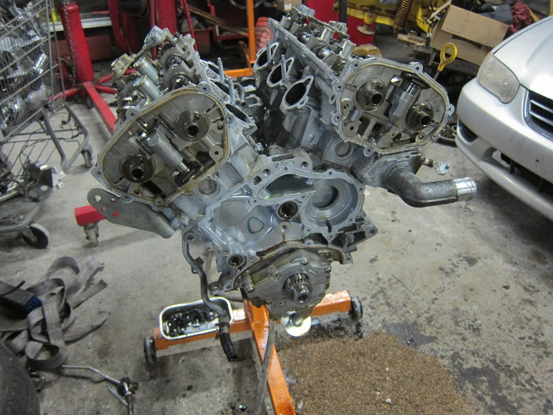
Stripped down:
The 07 Alti comes with dual knock sensors like the 09 Max.I unbolted both and put the VQ30DE knock sensor on rear bank.
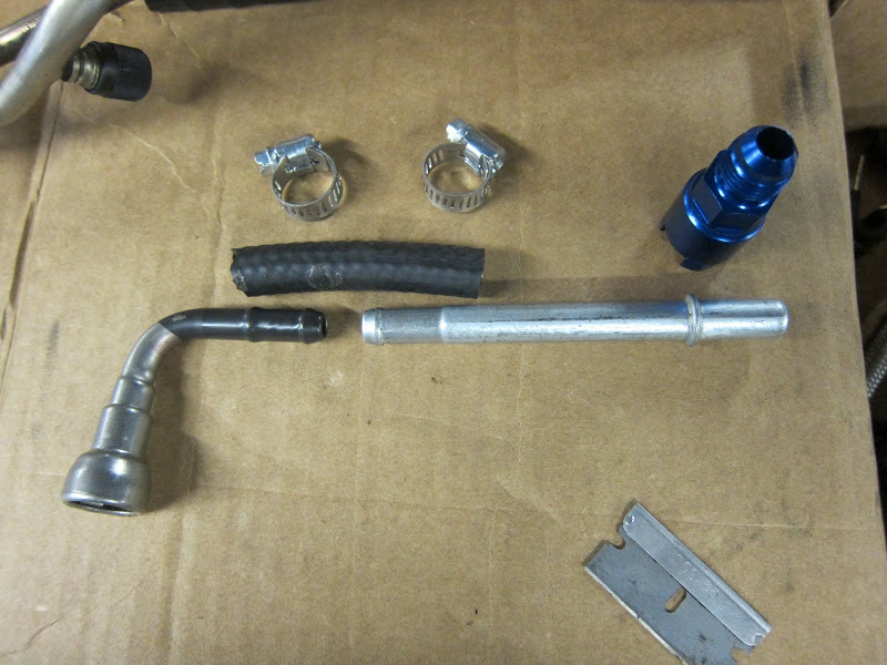
The Altima has a quick connect fuel fitting like the 09 max. My car already has AN lines from the filter. So, I need to get that quick connect to -6AN. I ordered 3/8″ and 5/16″ quick connect adapters by Earl’s since I wasn’t sure what size the rail was. The 3/8″ came but the 5/16″ is on back order. 5/16″ is the correct size and the p/n is 799-644120.
I got the 5/16″ to AN fitting on but because of the collar before the quick connect on the rail, the part that screws into the fitting to secure it needed to be grinded down. I have to get the car running asap. So, I did the following with what I had:
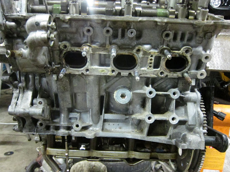
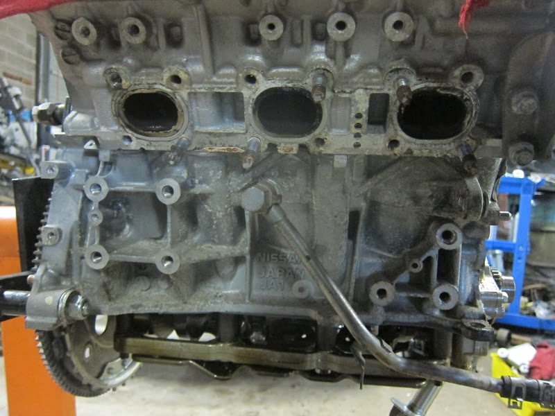
The cyl 5/6 exhaust manifold studs swapped:
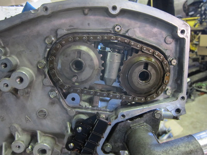
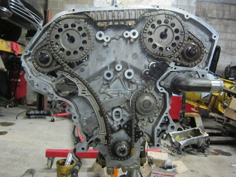
Drilled cams installed, Alti LIM and fuel rail installed with 380cc injectors, front of block prepped, and 07 Alti secondary tensioners primed. (Yes, the 07 Alti tensioners are used)
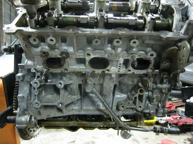
Shots of how the HR head went back to the VQ30 cam cap bolt pattern. So, no drilling of the inner timing cover is needed.
In my first post I mentioned how the stock 07 Alti intake cam dowel pin hole is close but not ideal timing. Instead of drilling near that hole and egging it out, I opted to drill roughly 180 from that hole through the primary and secondary cam gears and through the cam. This puts the dowel slots on the gears pointing in the right direction as if it were drilled like a typical 3.5 swap.
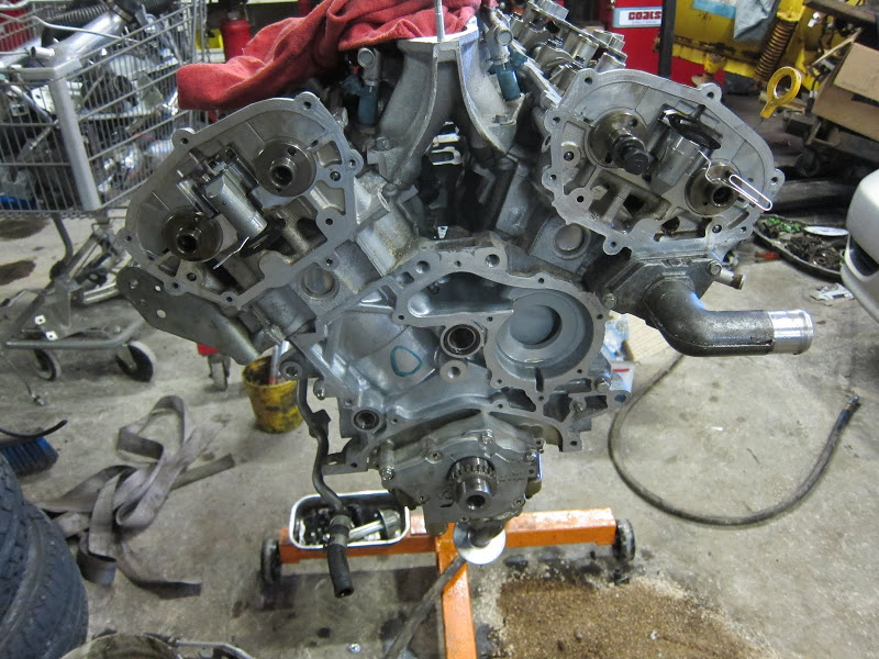
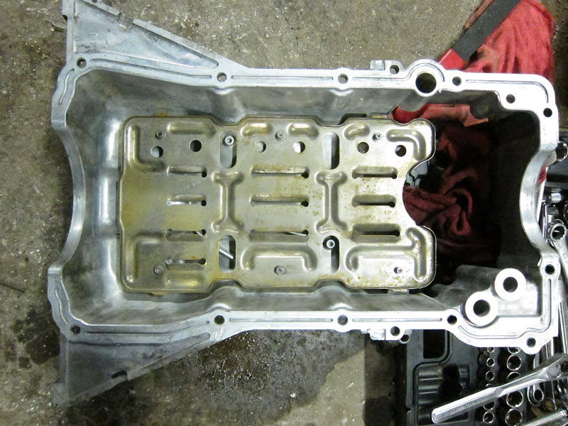
Removing the 3.0 windage tray since the 3.5 already one bolted to the caps/girdle.
Bolting the rest of the 4th gen crap back on
Close ups of the Alti oil cooler hose routing. The rear line needs to be bent slightly, the cooler sandwich is clocked counter clockwise from it’s stock orientation, the hardline that came with the engine has been bent slightly, 2 tabs removed, one re-drilled to bolt to the front of the upper oil pan with the a/c bracket, and a longer hose used from the sandwich to the hardline. A long rubber hose could replace the front hardline setup too. And the p/s belt clears no problem.
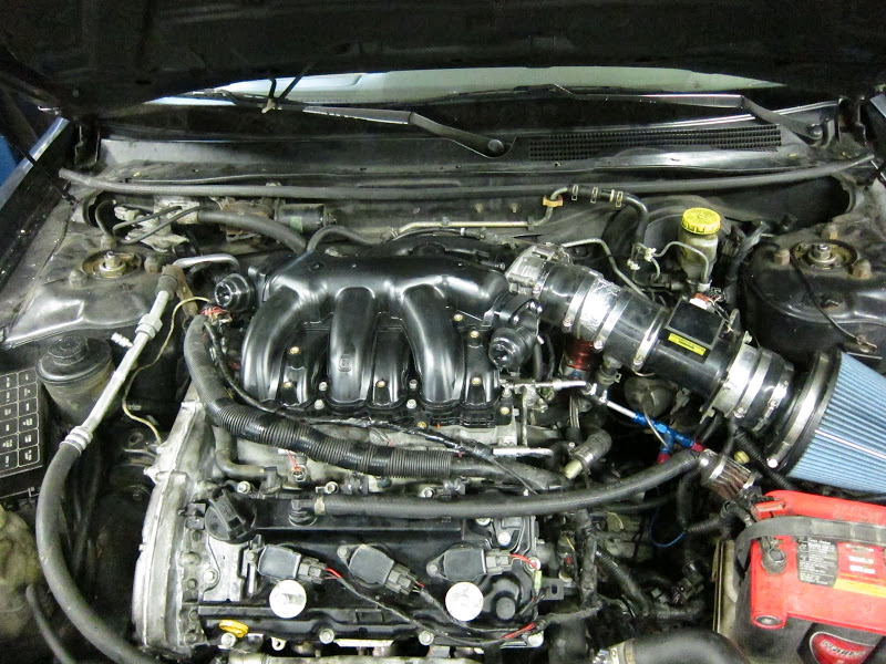
It’s ALIVE. This is as clean as this will ever be.. (notice the different rear main seal too)
Dirty but all together.
A couple other misc things with the swap:
The TB gasket mesh needs to be cut out if you’re pulling the TB cable from the top rear.
The bottom rad hose needs to be trimmed since the thermostat housing is a 90*.
I’ve yet to really push it but it idles good, runs smooth, and pulls good mid throttle. Somewhere in the near future I’m going to gut the upper and remove the VIAS valves. So, now we know how this is possible, not just that it is.
Additional Reference
Also, in the opinion of the OP, how does this differ, difficulty level/wise compared to the 02-08 engine swap?
The only two things that make this harder than a first-gen 3.5 swap is you have to swap the upper oil pan and drill the intake cams/gears. An adapter won’t work right due to the dowel pin locations being so close. (still need spacers though!!)
On those auto or CVT second-gen 3.5s with the CPS in a different spot you have to swap the upper oil pan anyway.
So, if you were going to drill the cams and use a second-gen 3.5 that came with an auto or CVT trans, it’s basically the same thing.
Nice work, any plans to dyno it? How much did that engine run you?
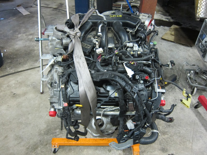
Yep, Once I gut the 09 upper and get the EMU in + tuned, I plan on getting on the dyno. I picked up the engine with 47k for $1400 including the $200 core charge.
Quick question about the cam timing on this swap. Would it be possible to use regular 05 max cams in the 07 Altima VQ so that I could use the adapters? I did some slight FSM research and they both have the same bearing/bore diameters. Only difference I can find is the lobe height witch is about .6 mm less on the max cams.
I am assuming the cam length and lobe placement would be the same but I would just like another opinion before I make the decision to try it. This way would just be 10x easier for me since I have multiple sets of 05 cams laying around, plus I don’t really have the resources to drill the Alti cams.
Yep, no reason you can’t run any non-HR head VQ cams with adapters. But, as with any cam swap, you’ll want to check the valve lash.
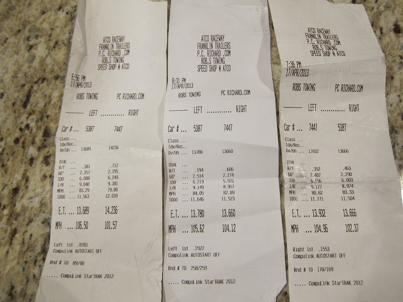
07+ Alti 3.5 Hybrid Swap, 98 i30 – Dyno Numbers
I got the new setup to the track tonight.
Track prep:
Removed throw rugs, spare, and jack
MT DRs Aired down 21 psi
No air filter
Year of Engine: 2008 Altima Engine Modifications: 3.0l timing, upper and lower oil pans, drilled intake cams/sprockets, 09′ Maxima upper intake and (75mm) TB, 3.5″ Intake, Q45 MAF, BPI flow stack, Aeromotive AFPR, Cattman headers, 3″ SS exhaust Y-back. Tuned: Rough tune with EMU Transmission: AE 5MT VLSD
PBs
60 – 2.195
1/4 – 13.66
mph – 104.96
Slips: (7447)
My 60 still needs work, as does my tune, the VIAS isn’t hooked up, and I was only shifting at 6600ish. But, all in all, I’m happy with the improvement over my last time at the track with the old 3.5 DE, 2.5″ exhaust, and stock 3.5 TB.
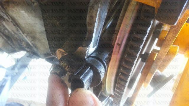
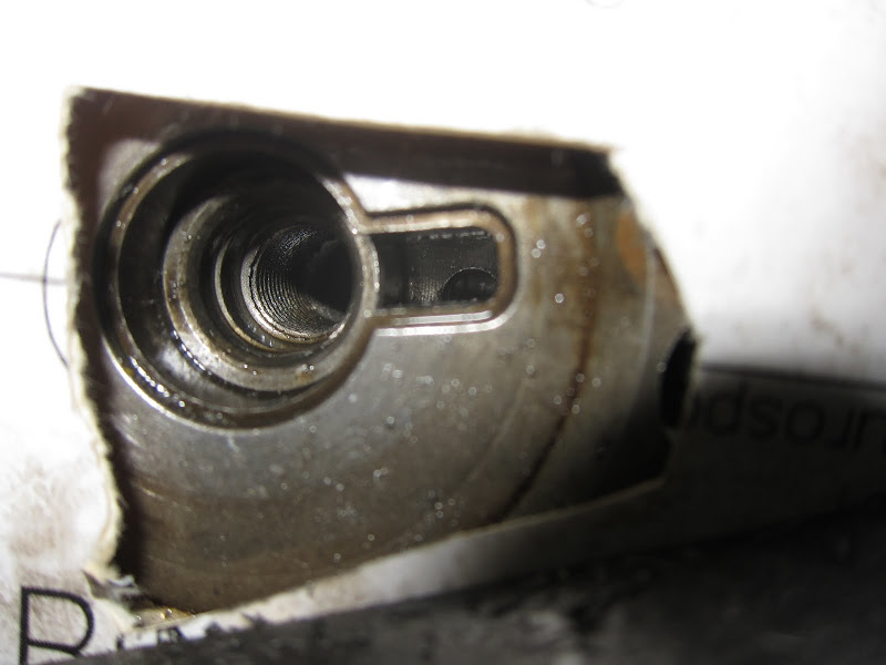
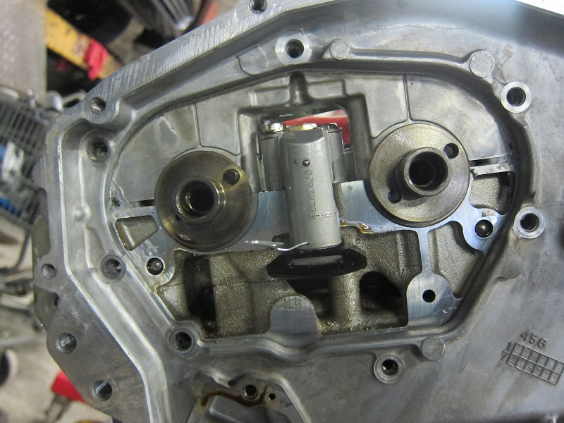
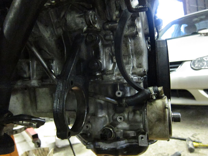
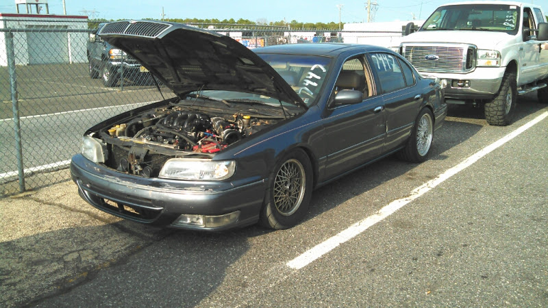
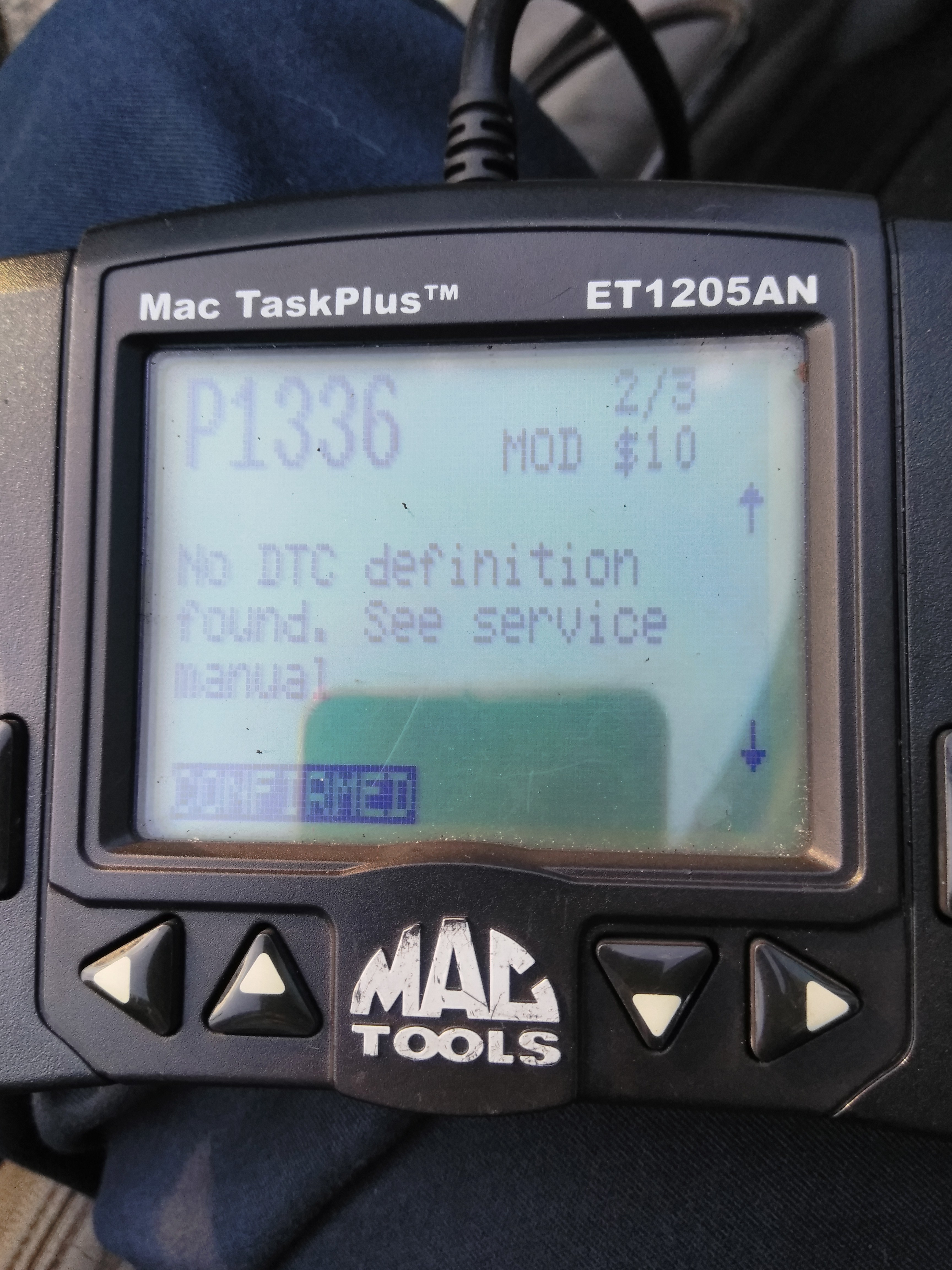
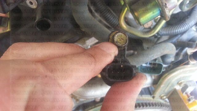
So since i bought the car back in 2010 it had the constant DTC p1336 crank position sensor POS. , it never really was a problem in the past, since the engine ran good, it had a hard start but always started up every time, and other than the DTC i never had a problem. Well i decided to reseal the oil pan since i was passing it on to my son who is going away to college i figured if i do more work on it, the less he has to do to it when it comes time to fix it.
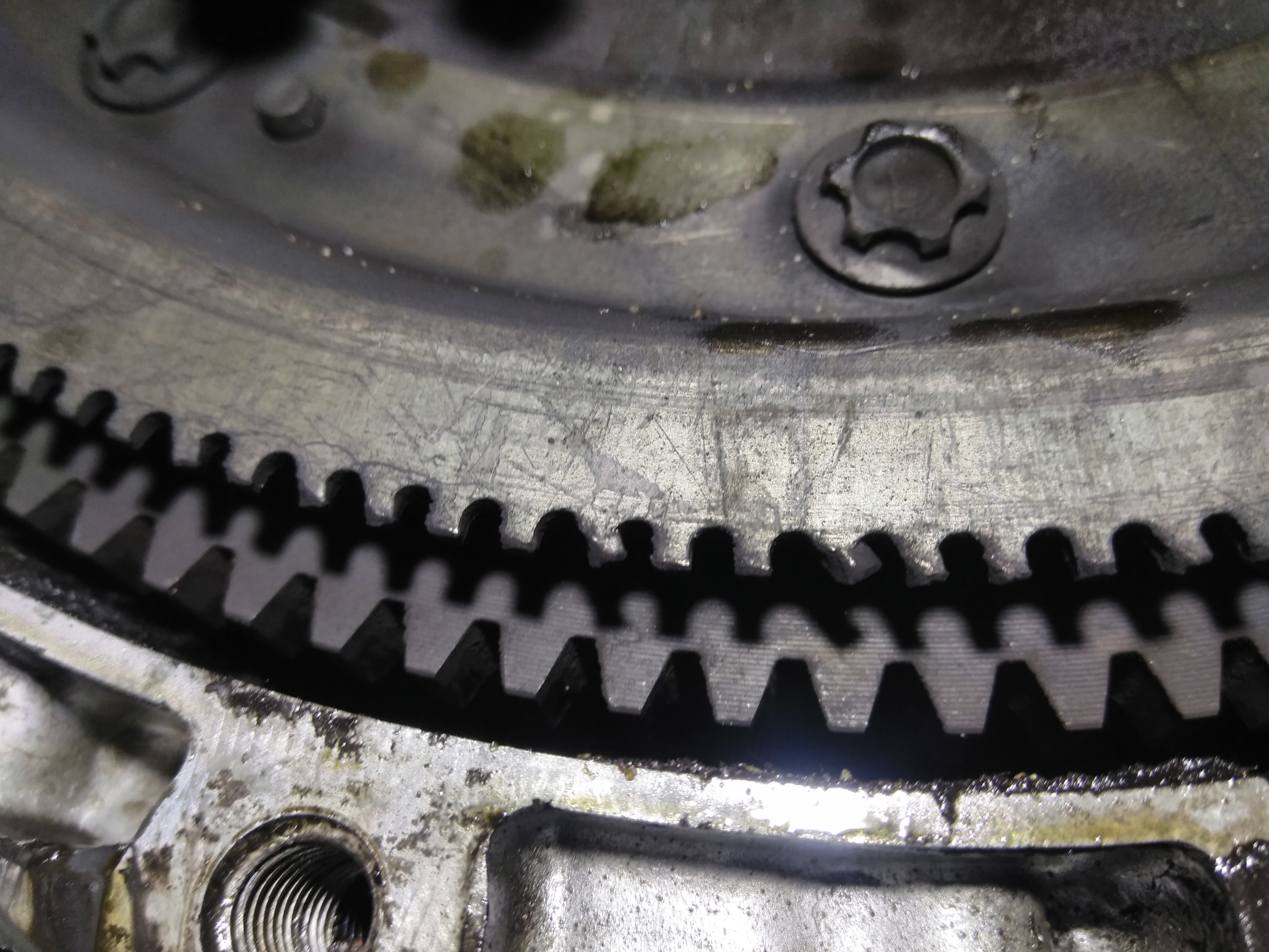
I resealed the oil pan and when i removed the pan low and behold i see my problem is the signal plate that is attached to the flywheel.
The kid i bought it from had the transmission and clutch replaced so when i got it the clutch was new so i had no reason to replace it , and if i had it long enough i am sure i would have had to replace it eventually. .
You can see the signal plate is damaged on the FW , i just wanted to share what i found just in case anyone has the same type of DTC and everything else checks out
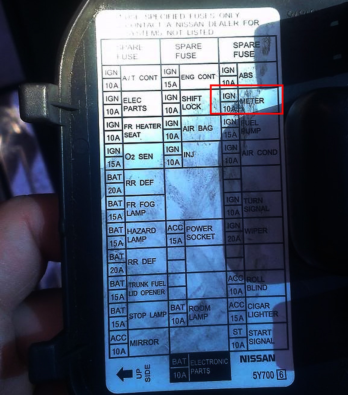
So I started blowing this in cab 10amp fuse called meter, I checked alternator, battery, called harness lights all the normal stuff, couldn’t find it, meanwhile that fuse controls the cluster and puts the vehicle into fail-safe mode… so I scoured the forums and google and was running out of free time and fuses, so I brought it into the shop (local mechanic)…
It took him 9 hours of following wire and circuit diagrams, Forums, calling Nissan dealerships, had everything unplugged from harness and couldn’t find what was causing the short…
He then noticed on the schematics for that circuit there was a mirror section, not side mirrors but rear mirror, apparently the connection at the actual rear view mirror was toast, melted the wires and shorted internally, unplugged mirror and voilaaa fuse didn’t blow.
So 870$ later I had the issue fixed, a measly 100$ mirror crippled my baby for 3 days and cost me 900$.
I’m just posting this so anyone that runs into the same issue to remember that the rearview mirror may not b on the diagram plainly, but it’s something to check also.
Additional Note:
THANK YOU SOO MUCH
This problem happens for me a while back and replaced the fuse and it didn’t pop it happened again and I spent the whole day looking for a short and YouTube videos and forums and I found this one went and looked at the wires behind the mirror they were barley touching so I pulled them apart and replaced the fuse again and it didn’t pop so thank you soon much for your forum.
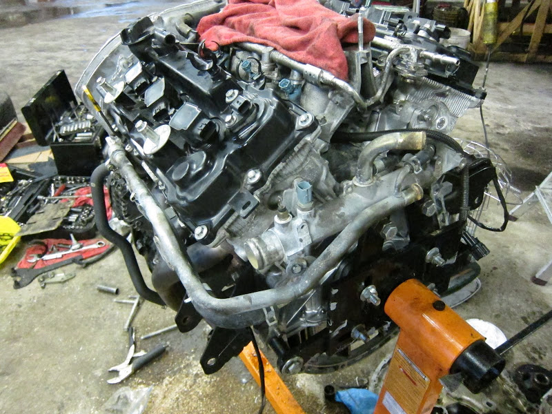
This an overview of the main items and modifications required to install a 2007+ Altima and 2009+ Maxima VQ35DE engine into a vehicle using a VQ30DE(K) Engine Control Unit (ECU).
Blue highlighted items need to be fabricated. Some items are produced by me (or in the design process) to make this swap easier.
Red highlighted items are new gaskets that are highly suggested to replace. I usually source my OEM gaskets from nissanpartsdeal.com.
This is intended only as reference material. Refer to the Factory Service Manual (FSM) for Removal and Installation procedures as well as torque specifications. I am not responsible for any damages blah blah.
2007+ Altima
2009+ Maxima
Upper Intake Manifold
Smaller Ports
Larger Ports
Throttle Body
70mm
75mm
*Maxima and Altima Upper Intake Manifolds are interchangeable*
Timing Components
To use the newer engine with the older ECU, all timing components and sensors will need to be replaced with that of a VQ30.
Cam adapters will be needed for this specific engine. –Currently available from schmellyfart@gmail.com. ‘StephenMax’ type Cam Adapters will NOT work.
VQ30 Outer Timing Cover and Access Plates
VQ30 Inner Timing Cover
VQ30 Water Pump 21010-31U85
VQ30 Timing Chains
VQ30 Timing Gears
1 Crank Sprocket
2 Exhaust Cam Sprockets
4 Intake Cam Sprockets
VQ30 Intake Cam Bolts – to be used on VQ35 Exhaust Cams
(VQ35 Exhaust Cam bolts to be used on VQ35 Intake Cams)
Torque Cam bolts to VQ35 spec.
Water Pump O-Rings
Seal- O Ring 21049-ZL80B
Seal- O Ring 21049-ZL80C
Block to Timing Cover O Rings
Seal- O Ring 15066-ZL80B
Seal- O Ring 15066-ZL80D
Front Crank Seal
Inspect VQ35 Seal – Sometimes this seal is new enough where is can be reused and inserted into VQ30 Outer Timing Cover.
Seal-Oil, Crankshaft Front 13510-31U10
VQ30 Timing Chain Guides
Main Timing Chain Tensioner
Either VQ30 or VQ35 Main Timing Chain Tensioner & Guide may be used, but they must not be mixed together. For example:
VQ30 Main Timing Chain Tensioner & VQ30 Main Timing Chain Guide
VQ35 Main Timing Chain Tensioner & VQ35 Main Timing Chain Guide
VQ35 Secondary Timing Chain Tensioners
These may need replacing depending on age of the engine because the VQ35 Timing Chain creates different grooves in the tension than the VQ30 Timing Chain that will be installed. Use only VQ35 Secondary Timing Chain Tensioners.
Oil Pans – A few options:
VQ30 upper oil pan, lower oil pan, and oil pick up tube.
VQ35 lower oil pan is deeper and narrower than VQ30 lower oil pan.
Pro: reduced chance of oil starvation on hard cornering
Con: Reduced ground clearance
Use dipstick that matches your lower oil pan!
Water Pipes
VQ30 Water Outlet Pipe (transmission side of engine)- VQ30 uses two coolant sensors, VQ35 uses one.
2x Water Outlet Pipe Gaskets -11062-31U00
Water Inlet Pipe (Near Front Valve Cover)
The HR head on these VQ35 has an extra port at the Water Inlet Connector for the Oil cooler. I personally found the Oil Cooler to interfere with Crank Sensor, so I removed mine – YMMV. If removing the oil cooler, this hole will need to be plugged via tap and hole plug, or Water Inlet block off plate – (Pending field test). (Oil Cooler removal will also require VQ30 Oil filter stud 11024-4P10A and Water Jacket Blind Plug 11051-60U2A). Once blocked off, VQ30 or VQ35 Water Inlet Connector can be used.
Gasket-Water Inlet 13050-31U05
Thermostat
If VQ35 Thermostat is used, approx. 2” of the lower radiator hose will need to be cut off of Thermostat end to fit. (2002-2003 Maxima Lower radiator hose MIGHT work without trimming – not yet verified)
VQ30 Thermostat will bolt up without issue.
Thermostat Gasket: Gasket-Water Inlet 13050-31U00
Injector Clips
1995-1999 Maxima needs VQ35 Injector clips soldered/crimped and sealed to the engine harness
2000-2001 Maxima Injector clips require no modification.
Fuel Rail
VQ35 has a returnless fuel rail.
Convert to returnless fuel system using guides on Maxima.org (Easier)
Modify VQ30DE-K Fuel Rail to fit VQ35 and retain return fuel system (Harder)
Throttle Body
The original Throttle Body (TB) is driven electronically, the VQ30 ECU requires a cable driven TB. Due to confined space around Throttle Flange, options are limited. A custom throttle body adapter or modified throttle body is necessary (Finalizing Design).
70mm 2001 Pathfinder TB w/ adapter. This TB is ideal due to OEM quality, TPS bolts up, and its Idle Air Control Valve (IACV) works very well with the VQ30 ECU. Minor wire harness modification required for IACV.
Heavily modified Mustang (Foxbody or SN95) TB
Heavily modified Q45 TB
Heavily modified VQ35 TB converted from electronic to cable.
Exhaust Studs
Cylinder 5 and 6 exhaust studs must be removed and installed in opposite holes in order to reuse older VQ30 headers or exhaust manifolds.
Valve Covers
VQ30 valve covers fit, but are also heavier. I would only recommend using the front VQ30 valve cover and spark plug cover if you want to keep it stealthy. Some Coil pack shenanigans may be required. Rear VQ30 valve cover is not recommended as the Upper Intake Manifold (UIM) does not clear the coil packs.
Emissions
Optional depending on personal preference. All emissions systems can be retained with the exception of EGR. Take good notes and mark the inlet/outlet of every emissions part, all can be reconnected to VQ35 UIM. Simplified Vacuum Hose routing diagram coming soon.
VIAS
Mine are currently installed but not controlled. Currently awaiting testing to verify optimal setup with VQ30 ECU.
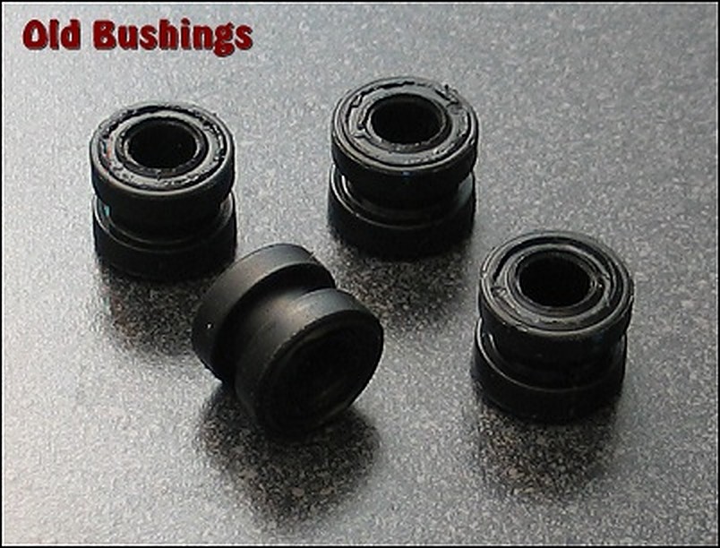
Part: Shifter Stabilizer Bushings – Nissan Maxima – 7.1115 Order Link: https://www.energysuspensionparts.com/7.1115
Here are the notes on removing the shifter trim and center console. Pictures follow.
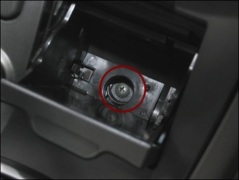
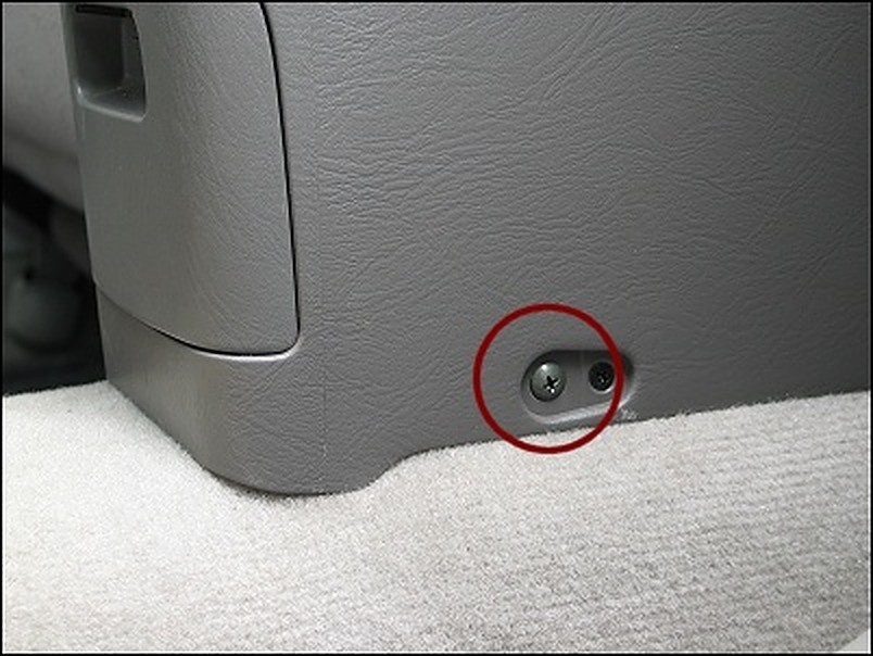
Remove the ashtray and the screw behind the ashtray. (picture)
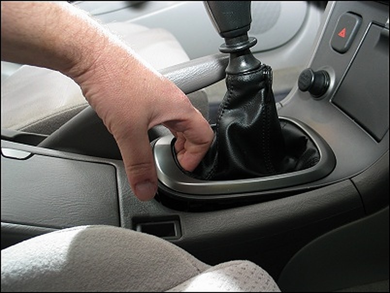
Unsnap the shifter trim by gently pushing your fingers into the leather on the back end for grip, then pull upwards to unclip it. (picture)
Lift the shifter trim from the back end, and wiggle it down from the front end. The shifter trim fits under the climate controls and will slip free with a little effort.
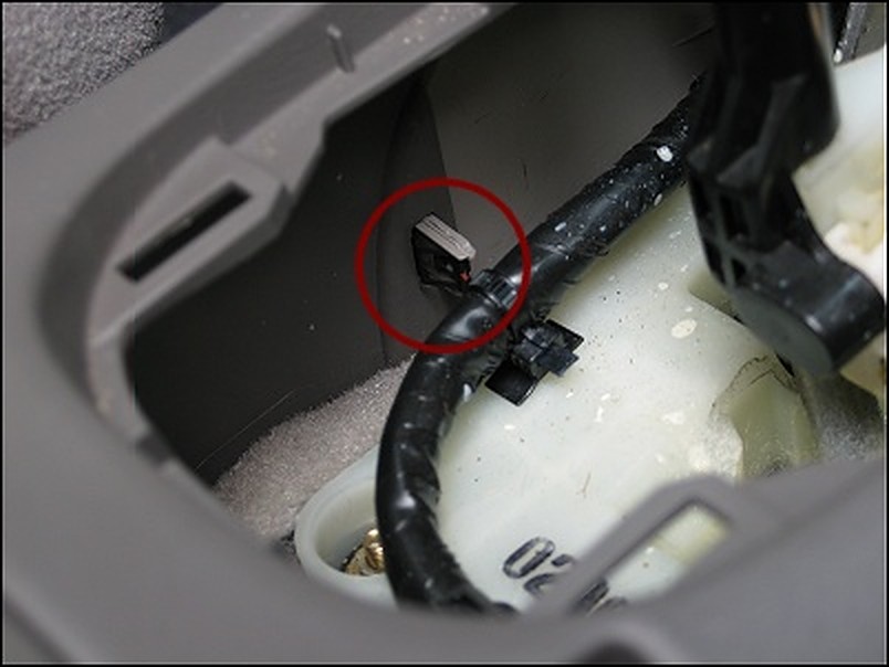
Once the trim piece is free, unclip the power connectors that go to the hazard lights, ashtray light, and cigarette lighter. (Yeah, there’s an ashtray light. Who knew?) Use a small flat-head screwdriver to help unclip these connectors.
Unsnap the leather boot and slip the entire trim piece off the shifter. Set it aside.
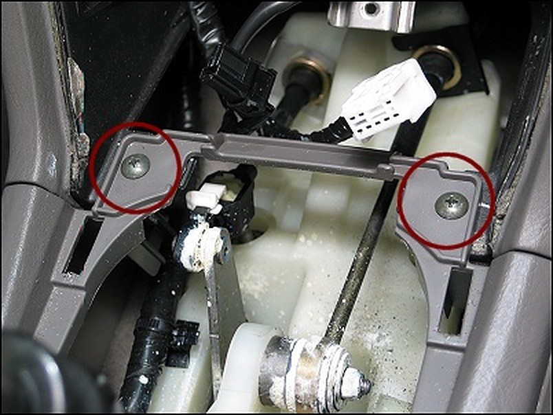
Now on to the center console. Unscrew the 2 console screws made accessible now that you’ve removed the shifter trim. (picture)
Unscrew the two (large) screws that are on the bottom sides of the console, accessible from the back seat. There are two screws here, you want the larger ones. (picture) I’m not sure what the other one is, but it’s not the one you want.
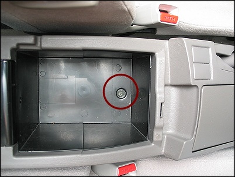
Unscrew the single screw inside the center console glove box. (picture)
Find the clips inside the front of the center console that attach the console to the side trim. (picture) Unclip the center console from the front-side panels, and lift the console up and out. It’s not a smooth process the first time you try to pull the console away, so take your time. Figure out how to remove it safely by adjusting the position of the hand brake.
Once the center console is free, unclip the power connector to the back seat cigarette lighter. Set the center console aside.
Next up are the steps I used to replace the bushings underneath the shifter assembly. eclid98 suggests wearing mechanics gloves for certain things. I don’t have any, and yes, I cut myself.
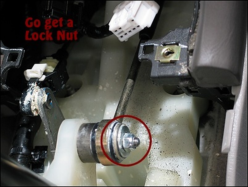
Disconnect the shifter cable from the shifter arm by removing the nut over the OEM banjo bushing. (picture)
Take out the OEM banjo bushing and replace it with the new ES banjo bushing. It can be difficult putting the new bushing in — use channel locks, or a couple of fat washers, a nut and bolt, screwing the washers together until the banjo bushing slips in. Do the same at the transmission end, under the hood. (I’m brushing past this part, because I already did this a while ago, and my playtime today consists of the bushings underneath the shifter assembly.)
Don’t put the cable back on the shifter arm just yet. However, when you do, do not use the OEM nut. Go buy a replacement lock-nut… the kind with plastic in the threads. You see, now that you’re loosened it, the OEM nut will just back off again in the future, and it’s been known to do so on a number of people. (Me included, but I was lucky and felt it getting sloppy before it completely fell off.) Use a lock-nut so you don’t have to deal with that worry.
Unclip the side-to-side articulating arm on the left side of the shifter. You do this by pushing it off its post, NOT by unclipping the white retention piece. That piece holds yet another plastic clip in place below it, who’s purpose is for fine-tune adjustment to the centered placement of the shifter’s left-to-right position. Play with it if you want to figure it out, but it’s not part of these instructions.
Now… you think there would be some kind of retention washer on this connector. The post is designed for it, but there wasn’t anything there. I’m thinking that was a manufacturing-line SNAFU on my car, so I bought an E-washer for that purpose, and used it when everything went back together. Go figure.
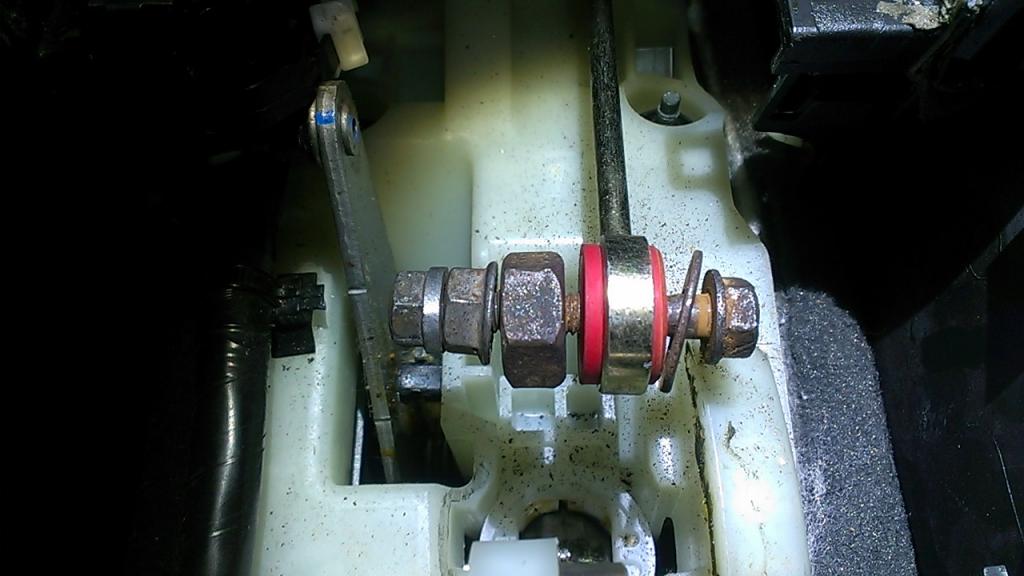
On to the shifter assembly. Use a 10mm socket to remove the 4 nuts that are holding the shifter assembly to the floor.
Wiggle and lift the shifter assembly off those four bolts. You don’t need to remove the entire thing; you just need to establish clearance one bolt at a time.
Working on one corner at a time… start by slipping the OEM metallic washer-tube-thingy (hereafter referred to just as the “washer”), off the OEM rubber bushings. Use a small flat-head to do this, prying the washer downward from the underside of the shifter assembly. Be careful you don’t lose this thing into the floorboards. That would be bad.
Once the washer is removed, use pliers or a big screwdriver to force the OEM rubber bushing out of the hole. You can pull it upward (difficult), or push it downward (easier).
Take the normal looking ES bushing and push it over the washer’s post (with a little force.) It’s probably easier to do this in your hand now, rather than after you re-install put the washer. (Thanks to eclid98 for that tip.)
Now slip the metallic washer back on the bolts. Note, you’re still working on the underside of the shifter assembly.
Repeat this step on the other 3 corners. You’ll probably cut yourself, bleed and swear a lot. It’s all part of the fun.
Now slip the shifter assembly back down over the four posts.
With the assembly back on the floor flat, slip the other ES bushing piece into the one of the holes, small end downward. Select one of the 2 more accessible corners as your first one. Don’t worry about forcing it down into the hole… that will happen next.
Put the OEM washer/nut over the bushing and screw the bushing down into the hole. Don’t tighten it all the way just yet, just enough to push the bushing down into the hole. (Thanks again, eclid98.)
Repeat this step on all four corners.
Last step — tighten down all four corners evenly.
Reference Photos
Additional Insight from: AWeb80
I do have a tip to put the banjo bushings in. Put a bolt that is smaller, not snug, through the bushing and use a nut to tighten it in place. I think the pictures explain themselves. It took all of 2 minutes per bushing. It pushes it in square and is MUCH easier than trying to squeeze it in w/ pliers.
*don’t mind the extra nuts I have on the left side….they are just there as spacers so I didn’t have to thread the actual nut on so far. *


 | P0650/P0462 Solution")


