Big shout to Rico for spending countless hours in finding a cost-effective solution to coilpacks for the VQ35DE engine. This also works on other models and years.
For those that don’t know, Audi coilpacks are stronger and better than Nissan coilpacks. They add better mpg and more HP/TQ. It works on bone stock vehicles or highly modified vehicles. Just rewire the OEM pigtails to Audi pigtails, plug it in and play!
Nissan Coilpack only has 1 coil. Audi has 2 coils as you can see in the picture below. By having 2 coils it doubles the spark output and can easily handle spark blow out that turbocharged vehicles suffer from. Because it’s outer exterior has a metal body it can dissipate heat ALOT quicker than Nissan rubber which helps with heat cycling. It’s also cheaper than OEM Nissan Coilpacks.
Audi R8 Coil Pack Advantages:
50,000 volts compared to Nissans/Infiniti 30,000 volts.
Some measure it with Kv so Nissans coils put out 21Kv while VW coils put out 30Kv
Quicker Heat dissipation. (Because of its metal body construction it can quickly dissipate heat. Nissan OEM body is made out of rubber that isolates heat instead of disperses it.)
More complete burn of the fuel mixture compared to OEM Nissan which equals to better MPG.
Idle Stability Improved
NO CEL (Check Engine Lights)
BEST PART ABOUT THEM IS THEY ARE CHEAPER $$$ than Nissan OEM yet they are much better.
Looks 10000% Cooler than OEM Coilpacks
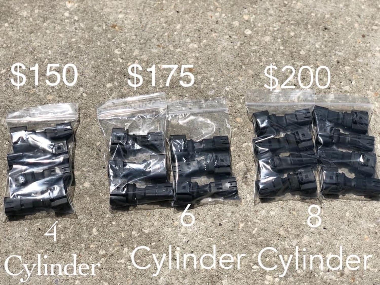
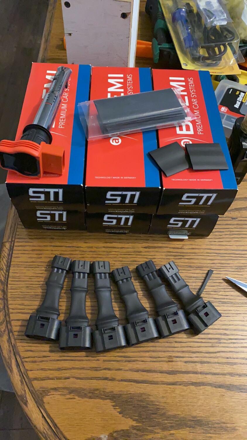
Now the coil packs price varies due to different name brands. They range from $132-$216 for a V6 engine. Below is the link of the coil packs below so you can see the prices and brands. Doesn’t matter which brand you use, I’ve tested them all and they all make the same exact power.
Installed a 2003 Nissan Maxima (Credit: Altaf Rahaman)
Important Note: The 02-08 DE Manifold requires NWP spacers.
Important Note:The 2nd Gen Engine does not require spacers. Straight plug-n-play.
Adaptor Options:
You can also purchase the adapters directly from Rico. Below are the prices.
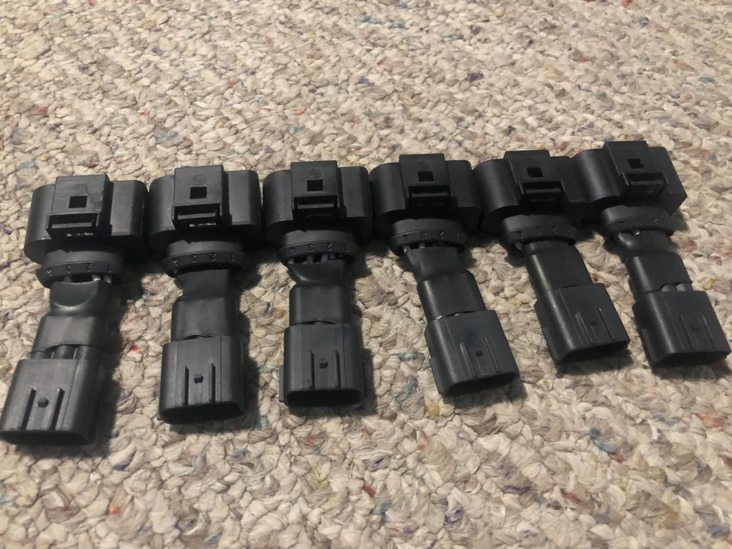
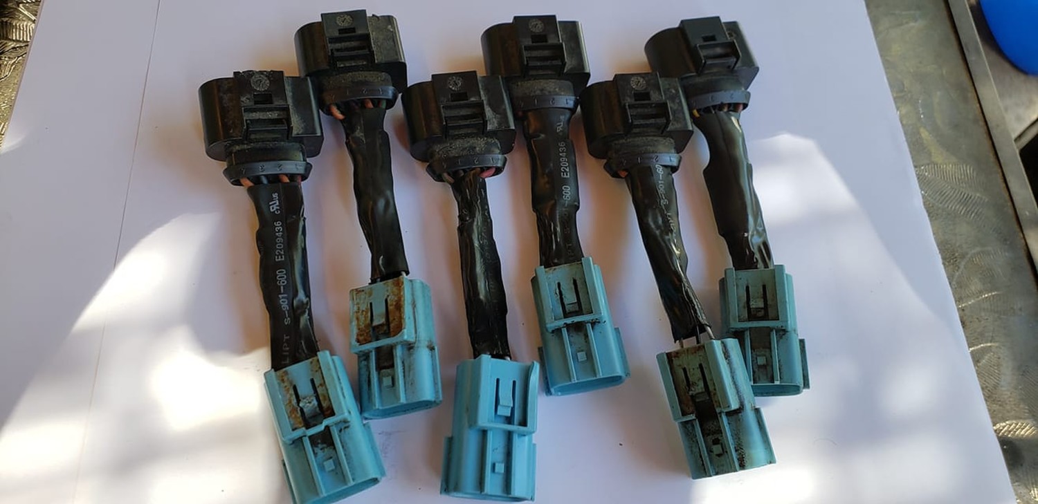
Create Connectors using O2 Plugs (Credit: Rob Tilley)
Finally got my R8 coils installed today and I must say it was definitely worth the time and money I spent. I installed them on my turbo 350z running 15psi with #7 plugs. Car runs so much smoother, especially under boost. It’s a totally different car. I used o2 plugs from a 02/03 Maxima to make the adapters for the plug. Just have to file down the alignment guide on the outside of the blue connector.
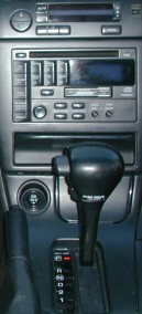
The ECU monitors the transmission-mounted speed sensor to determine vehicle speed. When the vehicle speed limit is reached, the ECU cuts the fuel flow to the engine to slow the car. Ok, in no way do I condone breaking any laws. I figured out how to get rid of the speed limiter on the 4thgen with automatic transmission. This also works on 5thgen Maxima with automatic transmission.
The signal path for the vehicle speed sensor is as follows:
Sensor to Speedometer
Speedometer to ECU & Cruise Control
If the signal is interrupted at the actual connection to the ECU, speedometer, odometer, and cruise control functions are preserved. The ECU does not receive a vehicle speed signal, therefore it will not limit the vehicle speed. This modification is easy. But beware, it does include modification of the factory ECU wiring harness…not for the inexperienced.
Tools and Supplies Needed:
Socket Wrench
Socket Wrench Extension
12mm Socket
Crimp Tool
Disconnect the negative battery terminal
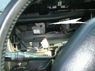
Remove ECU cover from passenger side footwell.
Loosen bolt in the center of the main ECU connector using your 12 mm Socket / Socket Wrench and Extension.
Unplug the main ECU connector. Remove snap-on plastic cover from ECU connector.
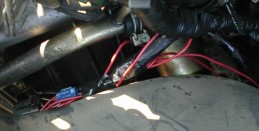
Locate PINK wire with BLUE stripe. (This wire is located on the right half of the connector when plugged in ECU PIN 29)
Cut PINK/BLUE Wire (It is recommended that you wire this up to a separate switch so you can turn it on/off when needed. Ensure that you do not cut the Fuel Temp Wire as it is also PINK/BLUE)
If you check the codes, you will get P0104 (Vehicle speed sensor fault) and P0504 (A/T control unit fault). To prevent the CEL you can use a switch to switch on/off for the quick burst for going over 120+ MPH. So far there have been no drivability problems associated with this mod.
Reassemble ECU connection and Reconnect negative battery terminal.
Verify the speed limiter/governor is removed by going past your previously limited speed.
Disclaimer: This mod is entirely up to you so do this at your own risk. This modification will cause the “check engine” light to illuminate.
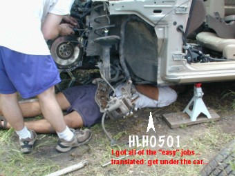
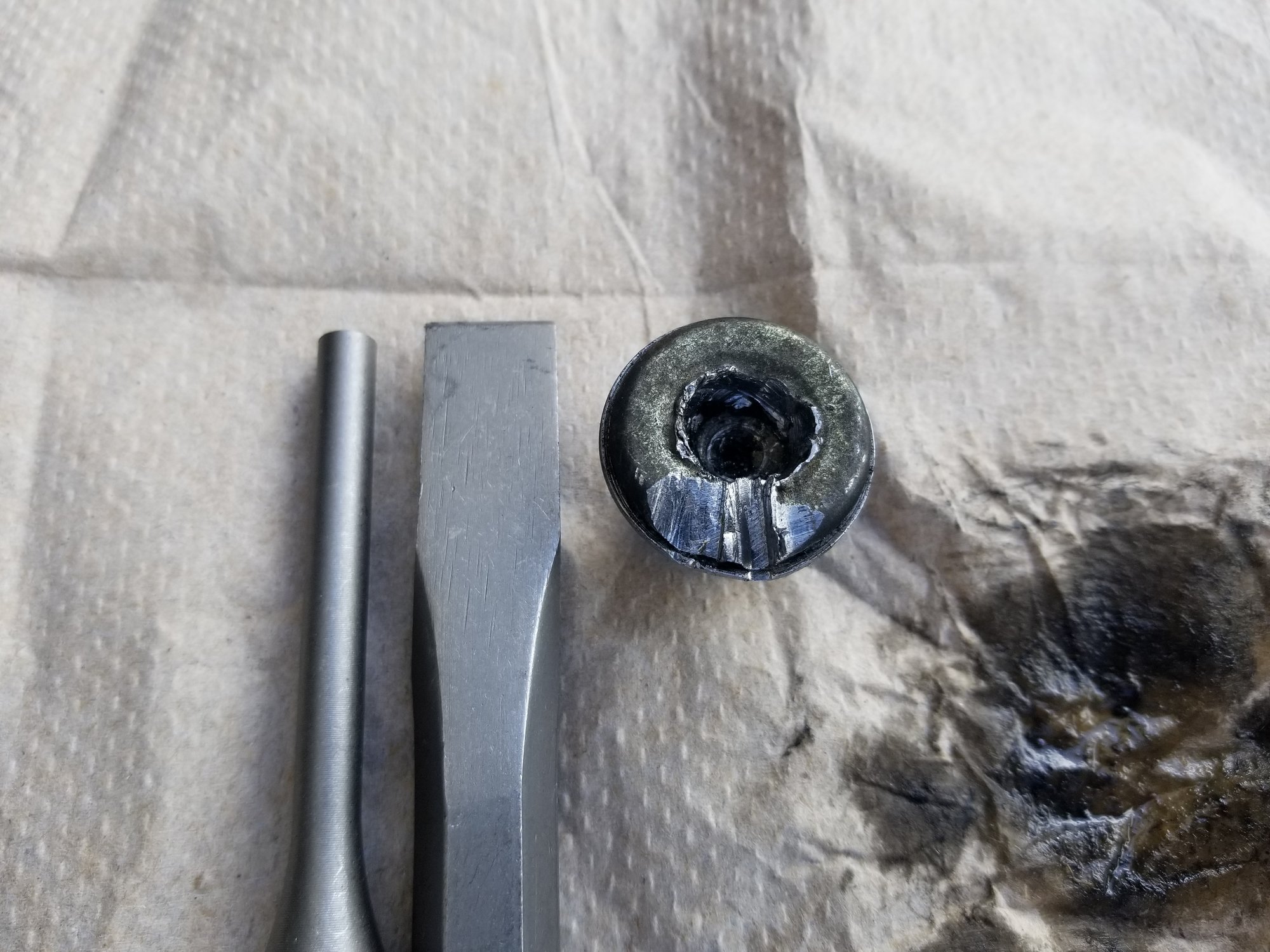
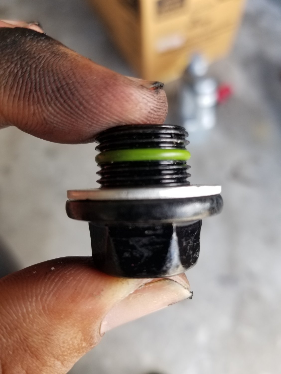
I started pulling my tranny today so I can change the throwout bearing and I stripped the drain bolt. luckily I found a video on Youtube on how to remove it with a chisel and punch.
I had ordered 2 new Smart-O R23 M18x1.5 drain plugs ahead of time for whenever I was going to need to change the gear oil in my transmission, the plug uses a 19mm wrench instead of a 10mm Allen bit.
In case you’ve disrupted your throttle body and need to perform the Idle Air Volume Relearn, you’ve probably noticed that it doesn’t “stick” , meaning it worked fine for the time being and then it didn’t.
I am using the Nissan Data Scan app with an ELM obdii Bluetooth adapter, the car’s 2000 Maxima GLE.
In order to make the Idle Air Volume Relearn stick using any of those apps and Bluetooth adapters, you can’t wipe any pending codes before/after Relearn is performed; for some reason when you use a third party app instead of Nissan Consult, it’ll write the changes onto the same partition as the error codes. What that means is you’re gonna write the IAVR over any pending existing codes in order to make it stay.
1. Don’t wipe any codes or clear the SES light
2. Perform idle air volume relearn
It’ll stay on your ECU as long as there is a pending code or the SES light is on. Once you clear the code and the SES light, your idle air relearn goes away as well. If you clear your codes and then do the relearn, your relearn will get overwritten once the code comes back. If you do the relearn with a pending code, it’ll stay there along with the code.
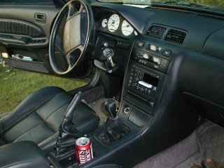
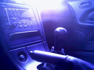
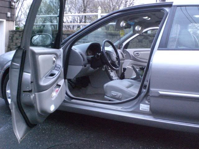
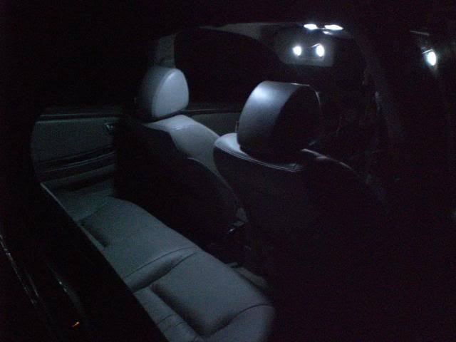
I just wanted to throw this together so people can see what what an LED interior looks like…in post number 2 and 3 ill put some detailed pics up.. Let me know what you think.. any questions feel free to ask…
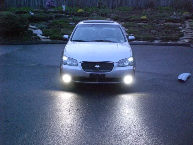
DAYTIME:
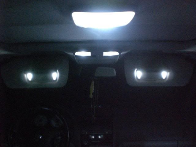
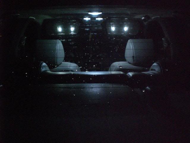
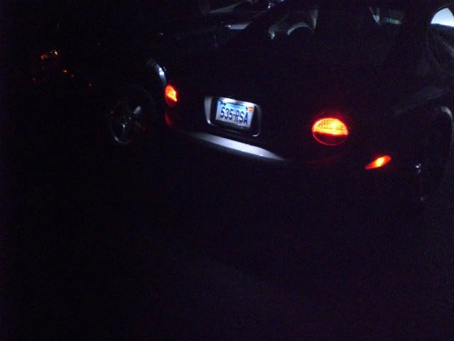
NIGHT TIME:
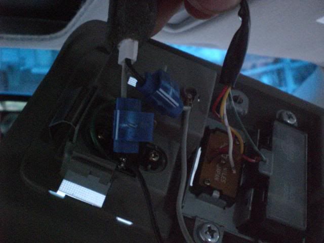
to get the map lights to work you need to reverse the polarity..once you remove the map light/sunglasses holder (2 phillips scerws in sunglasses holder then it pops off) you need to switch the – and + wires.. i did this by using quick taps as can be seen in this pic…
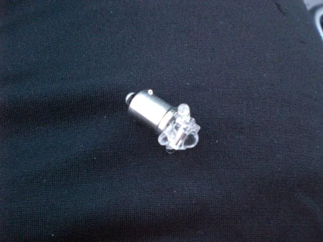
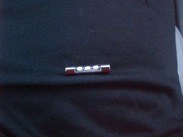
Heres the bulb I used,… Its a BA9 5 LED
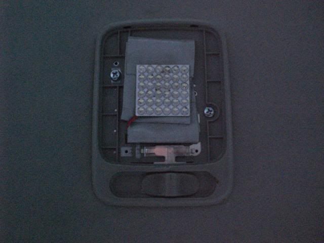
heres the Dome light.. i got a 36 LED circuit board that had a adapter on the end the fit in the festoon bulb i dont remember the exact size sorry…and yes thats duct tape lol
heres the bulb for the personal mirror lights…3 SMT vanity bulb
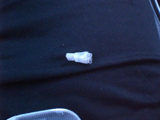
and the bulb in the doors.. 6LED bulb 194 wedge bulb
I used 194 wedge bulb that had 4 LEDs flat faced like the previous 6 LED picture above…. heres the license plate LED’s
oh and i also put the same LED’s in my running lights as my license plate lights 194 wedge 4 led-flat,..also in the pic..paired with 5K HID fogs
I just picked up my HR heads from Gord Bush who cleaned them up for me and flow tested them. We of course have previous numbers from the non-revup heads that I had Gord Bush port – so let’s compare! Visually looking at the HR heads you can see just how much bigger the intake port is than the non-revup heads, and the numbers prove it – the HR heads flow the same as the ported DE heads (in fact substantially more at low valve lifts). The exhaust doesn’t flow quite as well as the ported DE exhaust did, but it is still substantially better than a stock DE at high lifts.
Stock VQ35DE heads on the flow bench, very similar looking to the HR exhaust ports
Stock DE intake ports on the flow bench, substantially different than the HR
One reason the exhaust flows less at low valve lifts may be due to the fact that the HR has smaller valves. While this may be counter intuitive to those of you that go out there and buy the biggest valves you can, a smaller valve shrouds the combustion chamber less, and in-fact promotes flow at higher lifts. My imagination tells me you want the smallest valve and biggest port you can get away with, without overheating the valve.
Once these HR heads are ported, we should be able to get a decent bit more exhaust flow and hopefully crack the 400whp barrier with shorter intake runners and exhaust runners.
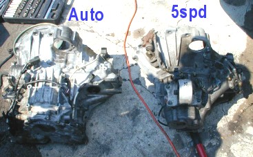
Automatic to 5spd Conversion Details for Nissan Maximas:
Parts Needed:
5spd Tranny (Try and Get the I30 Lsd or Canadian Maxima Lsd if Possible ? Doubt It)
Both Manual Drive Shafts (if You Have Abs You Need Specific Ones, if You Don’t Have Abs You Can Use Abs Ones)
1 Clutch Kit (Clutch Disc, Pressure Plate, Throw Out Bearing)
2 Shifting Rods (Support Rod + Control Rod) (Acquire Used W/ All the Hardware)
Return Spring (Connect to the 2 Shifting Rods (Buy This New, the Stiffer the Tighter Your Shifter Feels)
1 5spd Starter
1 Shifter (Acquire Used to Get Nuts and Bolts (Buy With the Shifter Rods)
1 Shifter Console Piece (Interior)
1 Shift Consul Bracket (Replaces Your Auto One) (Interior) (Dealer Name Plate Bolt and Transaxle Hole Cover)
1 Brake Pedal
1 Clutch Pedal
1 Master Cylinder
Hydraulic Lines for Clutch
1 Slave Cylinder for Clutch
1 Extra Set of Tranny Harnesses (Might Come W/ 5spd Tranny)
1 18ga Wire and Wiretaps
Assorted Cotter Pin Set.
1 Manual Fly Wheel
1 Manual Motor Mount
Tranny Fluid (Gl-4 or Redline is Preferable)
Locking Pin and Clip for the Clutch Pedal to the Master Cylinder (You Could Bend a Nail but I Would Go to the Dealer and Pay $4)
2 Nuts That Fit the Threads on the Clutch Pedal.
1 Bolt That Bolts in the Top of the Clutch Pedal (the Dealer Can Find It’s Size for You)
1 Bolt That Connects the Control Rod to the Tranny (the Dealer Can Find It’s Size for You)
1 Haynes Manual Just in Case You Need Extra Help
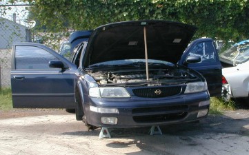
Preface: The whole idea behind a manual transmission is there is no electronics needed to run it ? basically, our slogan was, if the car starts and revs, the conversion will work. The converted car did not have ABS, but our donor car did ? ABS IS A PAIN because it sits right where you will run the hydraulic lines (In a factory 5 speed w/ ABS the lines run under the ABS brain)! Factor in more time if you have Antilock Brakes System. The converted car was a 1995 Nissan Maxima SE, and the donor car was a ’96 Nissan Maxima SE w/ ABS ? I don’t know about other year Maxima’s, but I would assume all 4th gens are somewhat the same when it comes to this conversion (please email me if you know otherwise). I am not liable if you mess up your car, mine worked PERFECT, but don’t blame me if you screw it up!
Before you do the conversion: Check to make sure that you can physically put the transmission in every gear before putting it in the car. Our first transmission’s shifting rod (part in the tranny) was slightly bent and we didn’t realize that we had to junk that tranny until AFTER we had everything finished and realized the car wouldn’t go into gear.
Overview:
1. Bypass the P-N start switch
2. Install pedals and clutch hydraulic system
3. Remove drive shafts
4. Remove tranny + torque converter
5. Install clutch setup.
6. Install tranny
7. Replace old shifter console w/ new and run shifting rods to tranny
8. Reinstall drive shafts
Bypass the P-N start switch
1.1 TAKE OFF BATTERY CLAMPS (neg and pos) to make sure you don’t mess something up electrically.
1.2 Remove the entire air box assembly and lines so you can see onto the top of your tranny.
1.3 Disconnect the harness that goes into the front of the tranny that only has 2 wires. (Note: the front of the tranny refers to the part that is closest to the front of the car)
1.4 Get your wire and cut a 6 inch strip
1.5 Use the wire taps to connect the 6 inch piece of wire to both of those wires (This will in effect connect these wires)
Add-on to the instructions:
In step 1.5, it says to connect two wires on the tranny harness. You instead, need to run a wire from both of the tranny wires, to the clutch pedal switch (small switch that is engaged when you push the clutch all the way down). This will let your car know when it is “Neutral (since it thinks it is an automatic)”.. your reason for doing this, is so that 1. You cant start the car without the clutch (safety)… and #2, SO CRUISE CONTROL WILL WORK.
1.6 Don’t reconnect the plug.
1.7 Connect the battery.
1.8 Put your parking brake on
1.9 Try to crank your car (Don’t start it, just see if it cranks)
If it does not, re-tap the wires or connect them in some way. And try to start again.
If it still does not start you can’t follow instructions and are not capable of doing this yourself since it is the easiest part.
2. Install pedals and clutch hydraulic system
Tools needed:
Drill
Phillips head screw driver
Metric socket set w/ extensions
Good drill bit set
Pencil
Tree bit (stone bit shaped like a tree, they sell it at Home Depot)
Cylinder bit (stone bit shaped like a cylinder, they sell it at Home Depot)
2.1 TAKE OFF BATTERY CLAMPS (neg and pos) you don’t want to burn anything up or blow your airbags.
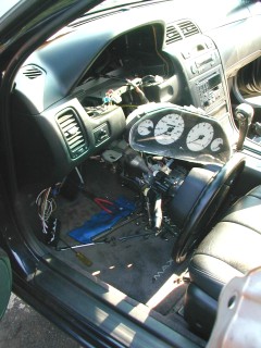
2.2 Remove lower drivers dash cover (2 Phillips head screws at the bottom)
Pull the cover off w/ caution not to damage the clips at the top.
2.3 Remove the Metal bracket just under the steering wheel (2 12mm bolts)
2.4 Remove the plastic shield from around the steering wheel column (6 Phillips head screws)
2.5 Pull the cover apart and off.
2.6 Remove the plastic housing around the Speedo. (2 Phillips. screws) pull it being careful not to damage the clips at the bottom.
2.7 Unplug the items that are mounted on it.
2.8 Remove 4 screws that hold in the Speedo.
2.9 Pull the Speedo out toward the passenger side. (you can leave it connected)
2.10 Remove the 2 12mm bolts that are now visible where the Speedo sat on the lower left side. That holds a bracket in.
2.11 Reinstall the Speedo. (Don’t worry about those screws needing to go back in)
2.12 Reinstall the plastic housing
2.13 Remove the clip and pin that hold the brake pedal cable on.
2.14 Remove the 4 nuts that hold the break pedal on.
2.15 Remove the 12mm bolt that holds the top of the break pedal on.
You will see where it goes because you will have manual one as a reference
Hopefully you have bought a matching bolt from Nissan, if not take it to the dealer and get one. You can’t install the clutch pedal w/out it.
2.16 Remove the 4 bolts that hold the steering wheel up.
2.17 Lower the steering wheel and let it rest on the seat.
2.18 Remove the metal bracket that the lowest left nut went on.
? Remember you took 2 bolts out of it before in the Speedo area.
2.19 Throw that bracket away. (It is useless.)
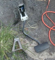
2.20 Remove the brake pedal.
2.21 Install the new pedal. (Put the 4 nuts on and the one bolt)
2.22 Put the locking pin in and the clip.
2.23 Bolt your wheel back up. (The three remaining bolts will be good enough.)
2.24 Look up where it seems the clutch should mount.
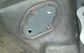
2.25 If you see a hole in the padding good. If not, you can see it outlined. (Pull it out)
2.26 Now you should be faced w/ a perfect padding hole but no hole through the firewall.
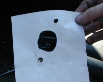
2.27 Make a trace of the master cylinder (I used cardboard)
It will have a big hole and 2 little ones for the bolts
2.28 Cut out your trace and slide it over the master cylinder to make sure it is accurate.
2.29 Mark the top of your trace (that canister on the master cylinder is up)
2.30 Fit it into that area that is punched out under the dash and draw an outline (pencil works great)
2.31 Open the hood.
2.32 Look into the upper driver side area against the firewall.
You will see the cruise unit.
It is the only electronic item in that area.
2.33 Remove it.
There will be one bolt on it and 2 nuts that you access in the wheel well.
2.34 Drill your 2 small holes for the master cylinder from your trace. (From the inside of the car was the easiest.)
2.35 Test the clutch pedal (by putting it through the holes you drilled)
The clutch pedal should be upright and level.
It should fit in there w/out force.
If it does not fit adjust the holes so it does.
2.36 Drill a good size hole in the big part of the trace (Where the master cylinder goes.)
2.37 Use your tree stone bit to make it bigger and work to carve out the hole to the traced size.
2.38 Use your cylinder stone bit to make it bigger and work to carve out the hole to the traced size.
2.39 Test the master cylinder in the hole.
If it does not fit correct the hole
Note: On a factory car w/ 5speed there is a spacer that is ? of an inch thick that is on the inside of the firewall. The 2 bolts that are on the clutch pedal that travel through the firewall go through this spacer, and somehow you will need to recreate it (VERY IMPORTANT!! that you get it just the right size, maybe buy the spacer from Nissan).
2.40 You can recreate it by getting big nuts that fit over these screws and using them as a spacer (or better yet, buy one from Nissan).
2.41 Install the clutch pedal and master cylinder.
2.42 Install the bolt you acquired to match the brake pedal bolt. (The car has this place built in just look for the place)
2.43 Install the locking pin to join the master cylinder and the clutch pedal.
2.44 Put the pin in it.
2.45 Reinstall every panel you removed except the one you tossed.
2.46 Pat yourself on the back.
3. Remove Drive shafts
Tools Needed:
Phillips head screw driver
Flat head screw driver
Metric socket set. (7mm-19mm)
Metric wrench set (7mm-19mm)
A good breaker bar
1.5″ socket that will attach to your breaker bar.
Needle nose pliers
1 jack
2 jack stands
Tie rod removal tool (You want the one that screws) (Buy at AutoZone)
3.1 Get on totally nasty “throw away” clothes because you are not going to even want to see them ever again!
3.2 Loosen lug nuts.
3.3 Jack the car up very high, to where the tires are about 9-12in above the ground. Place jack stands under it!!!
3.4 Remove your wheels.
Apply 3.5 – 3.14 parts to both wheels.
3.5 Remove the cotter pin from the center of the rotor area (Wheel Hub)
3.6 Remove the cotter pin from the bolt that connects the Knuckle and the Tie rod.
3.7 Insert the screw driver into the rotor (in those little holes around the diameter)
3.8 Remove that Huge Nut in the center of the rotor. (1.5 inch socket and the breaker bar will be necessary)
3.9 Get the washer off and keep all of these parts clean.
3.10 Remove the nut that holds the tie rod on.
3.11 Use your tie rod remover to loosen it on the knuckle. Then pull it apart.
3.12 Remove the 2 bolts that join the suspension to the Knuckle area.
3.13 Fold the knuckle (brake assembly) area out of the way while LIGHTLY banging on the end of the big threaded shaft you removed the large nut from
Don’t screw up the treads. You can protect them by putting the nut back on and making it even w/ the end.
3.14 You should now have the driveshaft hanging free on the outsides of the car.
3.15 On the driver’s side, push the driveshaft in a little bit (It compresses), and yank it out ? you might have to do it a few times before it comes free. (It will POP out)
3.16 Remove that driveshaft and be very careful not to break the rubber boots.
3.17 On the passenger side, you must go under the car and find the support that the driveshaft goes through before it gets to the tranny. It’s a pain to get at, but there are 3 bolts in a triangle around the outside of the support holding the driveshaft in.
3.18 Remove the three 12mm bolts, and then push in the shaft and pull it out. Be very careful not the break the rubber boots and gently set the two drive shafts aside.
3.19 Pat Yourself on the back you have successfully removed your drive shafts.
Note: Your Shocks/Springs are only 8 min and 3 bolts away from replacement if you want to do it at this time.
4. Remove tranny + torque converter
Tools Needed:
Everything from drive shaft removal.
1 hydraulic Jack
1 Nissan Factory Jack
2 bricks (You might need them, depends how high your car is)
One extra person
4.1 You now must remove your whole air intake system from the top of the engine. Everything including the rubber 3″ flexible hose. (After your MAF and all that) and unscrew the little clamp. Gently pull it away, and take out all the other bolts (this will be a little different if you have pop vs. cai vs. stock) so you can figure it out. Get all those hoses off and out of the way, so you can see easily down to the tranny.
4.2 Remove all plugs that go into the tranny.
4.3 Remove the dipstick for the auto tranny , it has one bolt at its base.
4.4 Remove the rubber lines that go into the tranny, you can cut them because you won’t use them again.
4.5 Remove the plug that connects to the starter
4.6 Remove the fat wire (pos) that connects to the start itself.
4.7 Remove the starter. (2 17mm bolts)
4.8 Pull the starter out.
4.9 Remove the plastic panels from the driver side wheel well so you can see the side of the tranny.
4.10 Remove the linkage line that goes to the front of the tranny (Fat cable that bolts next on at the front left corner of the tranny)
4.11 Put your hydraulic jack under the tranny.
Just on to the tranny, not so much pressure you are jacking the engine up.
4.12 Remove all the bolts that bolt the tranny on (there are 17mm on top and 14mm on the bottom) except for one 17mm on the front. Just loosen it a little.
These bolts will be hard to break and you will need a breaker bar to loosen them.
4.13 Put your Factory Nissan jack under the support beam (Runs under the Engine/Tranny) toward the front, up close to those 2 bolts but leave enough room so you can loosen and remove them.
This is where you might need the brick to get up to the beam.
4.14 Look down from the top on to your tranny.
4.15 You will see a motor mount sort of next to your battery w/ 4 bolts going into the tranny
4.16 Remove these bolts.
4.17 Very slowly, lower the transmission 1/2″(Hydraulic Jack) and then the engine 1/2″(Nissan Jack) until they are sitting very low where the transmission is clear of anything in its way coming off the engine.
4.18 Remove the last 17mm bolt that holds the transmission onto the engine.
4.19 Have your extra person ready.
They will work the jack as you do the wiggling, wedging and clearance checking
4.20 Look for a place between the tranny and the engine that you can stick a screwdriver
4.21 Crack the seal w/ a screwdriver.
4.22 Now pull the tranny away from the engine wiggling it off the engine gently (don’t let that rod be bending around or rest the weight on that center shaft!)
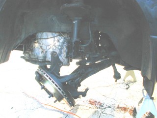
4.23 Now, using the jack slowly lower the transmission to the point where you can roll it out the driver side wheel well.
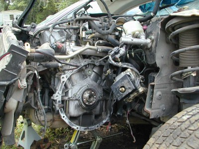
4.24 You are now looking at the torque converter mounted on the engine.
4.25 Go get some food and Pat yourself on the back.
4.26 Look at the bottom of the engine (Sort of from the passenger side) and you will see a black cover w/ 2 small bolts.
4.27 Remove the bolts and the cover.
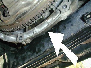
4.28 While looking through this hole use your screwdriver to rotate the flywheel around on the teeth of the flywheel until you see a bolt.
4.29 Use the screwdriver as a wedge to prevent the flywheel from turning and remove the bolt.
4.30 Repeat for all four bolts.
4.31 Slide the torque converter off.
4.32 Now look at the flywheel and you will see 8 bolts in the center bolting it to the crankshaft.
4.33 Use your screwdriver wedge to break loose all the bolts.
4.34 Remove the bolts and your flywheel.
4.35 Remove the bolt that holds the tranny motor mount and remove it.
The manual one is different.
4.36 Good job, you just ate so I would continue installing your new clutch setup.
5. Install clutch
Tools Needed:
Torque wrench
Hayes Manual
Metric Socket Set
Screwdriver
Clutch aligning tool
5.1 Take your flywheel, line it up on the engine, and attach it in place of the old one.
5.2 Torque it to the specs in the Hayes Manual, using your screwdriver wedge.
5.3 Make sure the flywheel is VERY clean, no grease on it? if there is use 409 to clean it, and sand it with 180grit or more sandpaper. VERY IMPORTANT that it is clean
5.4 Put in your clutch aligning/centering tool in the engine hole.
5.5 Slide your clutch on over the tool.
5.6 Slide on the centering piece of the tool and get the clutch just right.
5.7 Put on the new pressure plate you have, make sure the clutch is centered and pressure plate lines up right, and bolt it all down, making sure you do it with a torque wrench as it is VERY important in there.
5.8 Remove the tool.
5.9 Now go get some sleep seeing you probably did most of this yourself and it took all day.
6. Install the Tranny
Tools Needed:
Torque wrench
Hayes Manual
Metric Socket Set
Screwdriver
1 hydraulic Jack
1 Nissan Factory Jack
One extra person
6.1 Put the manual motor mount back up into the car w/ the “M” symbol facing the engine.
6.2 Put the 5spd tranny on the jack and roll it in through the wheel well the same as you took the other out.
6.3 Slowly lift it up w/ the jack to where it seems to be aligned.
6.4 Make sure that it is lined up just perfectly level w/ the engine when doing this, because once you put it on the engine, it is virtually impossible to rotate it and it HAS to line up PERFECT for the bolts to go in (Can be very frustrating)
6.5 Here is the hardest part, wiggle the transmission over toward the engine until it is flush.
Be sure to have the shaft going through the middle of the of the pressure plate.
If it won’t continue to travel rotate the flywheel (w/ your screw driver) just a little and try it again.
The shaft and clutch have little teeth that need to align.
6.6 Quick put a bolt on (The front 17mm is the easiest)
6.7 Work all the way around the tranny putting the bolts on. You might need the jack to make small alignment adjustments to get some bolts on.
Make sure and leave the bolt (or both of them if you are going to try) for the shifter stabilizer out so you don’t do it twice
6.8 Lift the tranny 1/2″ and the engine 1/2″ and so on and so forth till its back up.
Have your helper make sure the motor mount does not bind and lines up w/ the holes on the tranny.
6.9 Put the bolts in the support beam and the motor mount onto the top of the tranny.
6.10 Put in the starter using the two bolts.
6.11 Torque all the bolts to spec.
6.12 Connect all the wires back to the starter.
6.13 Plug in whichever harnesses still plug together.
6.14 Put the plastic panels back on in the left wheel well.
6.15 Fill the tranny w/ fluid using the holes where the drive shafts go in.
It is full when fluid starts coming out of the hole.
6.16 You are almost there you have done everything hard.
7. Replace old shifter console w/ new and run shifting rods to tranny
Tools Needed:
Phillips head screw driver
Flat head screw driver
Metric socket set. (7mm-19mm)
Metric wrench set (7mm-19mm)
A good breaker bar
1.5″ socket that will attach to your breaker bar.
Needle nose pliers
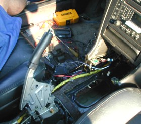
7.1 Now comes some fun. From inside the car, pry up the console piece that sits around your automatic shifter w/ the screwdriver.
7.2 Pull it off and out of the way.
7.3 Take the screw out that holds the shifter handle on.
7.4 Pull it up and down while trying to pull the button off. It will come off the shaft.
7.5 Remove the cover w/ the shift indicators on it (has some Phillips head screws)
7.6 Look down into the hole and you will see 2 cables coming in.
7.7 The small one on the left (Toward passenger side) is the key release linkage.
7.8 Remove the clip that holds it on and pull it out a little (in only moves 1/8 of an inch) wrap tape around it so it can’t move. I does not want to move so don’t worry.
7.9 Remove the larger cable and bend it out of the way.
7.10 You can remove the cable or cut or bend it, it was what changed the gears in the automatic but is now useless.
7.11 Remove the 2 nuts on the top that holds the Aluminum frame onto the painted area of the car.
7.12 There will be two nuts holding the assembly up from the underneath ?
7.13 Go under the car, and pull the rubber things that hold your exhaust up? there are 3.
7.14 Unbolt the heat shield on the ends (not in the middle) so you can get under it.
7.15 Take out the two bolts from the bottom that hold the shifter piece in your car, and remove it from the top.
7.16 Run the two shifting rods above the heat shield.
7.17 Put the shifter piece in the car from the top, but don’t bolt it.
7.18 Go back underneath the car and put the spring in (It runs between the 2 rods)
7.19 Bolt in the shifter.
7.20 Attach the support rod (W/ 2 bolts if you can get them) to the Tranny/Engine.
There is only one place it will bolt so it won’t be too hard to find.
7.21 Attach the shifter control rod to the transmission
7.22 Put trim piece back inside of car and screw on the shift knob.
—>
8. Reinstall drive shafts
Tools Needed:
Phillips head screw driver
Flat head screw driver
Metric socket set. (7mm-19mm)
Metric wrench set (7mm-19mm)
A good breaker bar
1.5″ socket that will attach to your breaker bar.
Needle nose pliers
1 jack
8.1 Reinstall the MANUAL drive shafts. (They are different then the automatic shafts)
8.2 Put the left one in first.
8.3 Put the shaft in as good as possible. (Be careful not to damage the boots) Then sort of extend the joints and slam them together. The idea is to make it into a self-sufficient hammer. Until it clicks into place. It will!!
8.4 Reinstall the Knuckle (Brake assembly).
8.5 Remember your big washer and be sure to get that big bolt tight.
8.6 Put passenger drive shafts back in, don’t forget the triangle that locks the passenger side one in.
8.7 Put center driveshaft bolt back on, cotter pin in, control arm bolt and cotter pin, and two bolts that mount the wheel to the suspension.
8.8 Wheels back on, drop the car.
8.9 Turn the car on; let it idle for about 30 ? 60sec to make sure oil gets through the engine and tranny.
HAVE FUN!!!!!! Remember you have to BABY that clutch all the time for the first 500+ city miles
REVERSE LIGHTS WIRING: (Thanks Stephen Max for write up)
The back-up lights turn on when a circuit is completed when the transmission is in reverse. This is true for both automatic and manual transmissions. All you have to do is find the correct wires in the automatic harness that go to the gear selector mechanism of the automatic, and splice them into the wires that go to the neutral/reverse position indicator on the manual transmission.
1. Look for a large, gray wiring harness connector that is unused. This used to carry a bundle of wires to the gear selector mechanism on the front of your automatic transmission. This harness connector should just be dangling somewhere around the top of your manual transmission about where the slave cylinder is. There are eight wires that go into this connector. The wires you need to find are the solid green wire and the green/white wire. Splice two wires into these two. To test to make sure you got the correct two wires, turn on your ignition and touch the ends of the two splices together. Your back-up lights should come on regardless of what gear you are in.
2. Find the harness that comes from the neutral/reverse position indicator switch on your manual transmission. The switch is the one that is down at the bottom of the transmission and there are four wires in that harness. The wires you are looking for are the blue wire and the blue/red wire. To make sure you got the right two, put the transmission into reverse and get a multimeter and check the resistance across the two pins in the connector that correspond to the blue and the blue/red wires. The resistance should be near zero.
3. Now just take the two splices from the auto harness and splice them into the blue and blue/red wires in the manual harness. It doesn’t matter which splice goes to which wire.
Now, for the questions everyone wants me to answer..
1. Q: Is it really worth it? A: It is a whole lot of work, I will say that right now. When you are doing it, it gets frustrating and seems almost not worth it. When you take your first ride in it converted to 5spd, it makes everything worth it 10x!!! And then to realize you get to drive it every day as a 5spd from then on. Without a doubt I would do it again in a heartbeat.
2. Q: Does it really work and is it still running? A: Yes, I have been running on it for over a year now, with no problems. The thing runs AWESOME, no trouble from it so far (knock on wood) and I have really DRIVEN the car a TON(
3. Q: How much did it cost? A: This is the hardest question to answer… can’t really give you a dollar amount. People are paying anywhere from 800-1500$ for all the parts (check a bunch of junkyards, even if they have to ship the stuff…). Then labor, you can attempt it yourself, its not super difficult but it isn’t exactly like putting a strut bar on.. I would advise having someone who is very experienced do it with you, or pay a shop to do the labor (prices can vary a TON!!.. 500-1500+$)
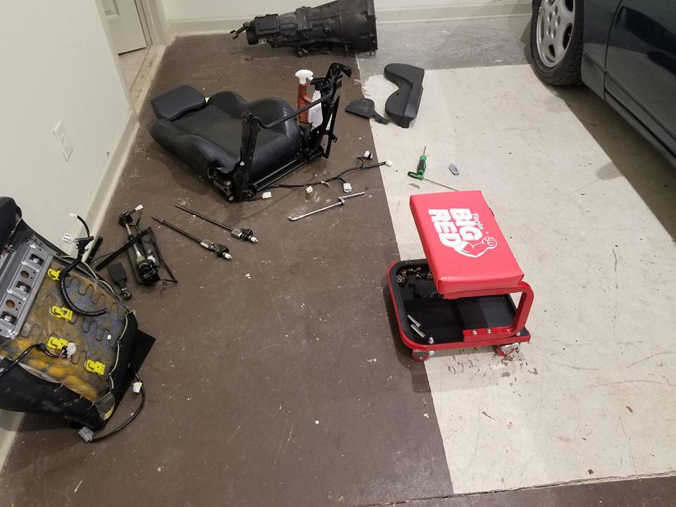
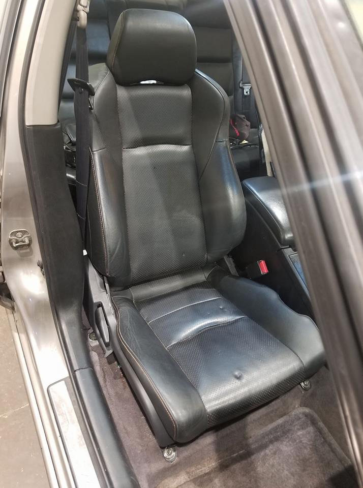
Some of you may have seen this in a few other Maxima groups. I did a 350Z heated and power seat swap into my 2002 Maxima. I used the 350z seat rails and all. I cut the 350z mounts from the rails and bolted the rails to a set of aftermarket brackets. Used existing heated seat wiring in the Maxima. Also had to trim the side panels off the 350z seats. I gained around 2 inches of headroom. I love them. No more sliding around in the turns. That..and they look great.
Please note that this post is for reference and documentation purposes ONLY.Matt Blehm no longer offers these products or services. Products were available from 2003 to around 2009.
BlehmCo Maxima Big Brake Kits
Front Big Brake Kit #1–2004 Maxima Rotors with 300ZX calipers: This kit fits all 1989 through 2003 models
Front Big Brake Kit #2–2004 Maxima Rotors with OEM 5th generation calipers: This kit only fits 2000 and 2001 models
REAR Big Brake Kit This kit fits all 1995 through 2003 models!
BlehmCo Maxima Front Big Brake Kit
This kit uses easy-to-find, off the shelf ALL Nissan parts! That way the next time you warp a rotor, or wear out the pads at an Auto X, track event, etc…you can just go to the local parts store and pick up replacement parts! Not many BBKs will allow you to do that!
So what’s in this kit?
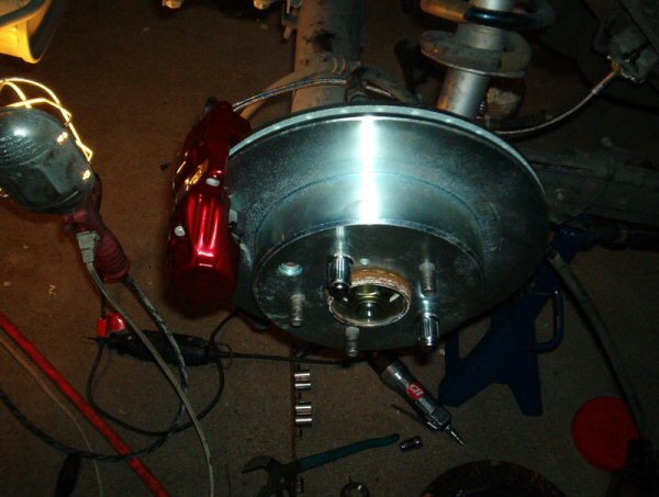
NEW OEM 12.6″ 2004 Maxima Rotors (included in the Complete and Basic Kits)
Used/Rebuilt/Remanufactured 300ZX ALUMINUM calipers, hardware, pads, shims, etc (included in the Complete Kit).
Caliper relocation bracket
All hardware necessary to install (nuts, bolts, washers, etc.)
Goodridge Stainless Steel brake lines, certified to D.O.T. FMVSS test 106 (many of the brake kits out there don’t have this)
As noted above, the kit is offered with and without the 300ZX calipers for those of you who already have some, or have a good source for them already. If you’d like me to source them for you, then prices are at the bottom of the page.
What are the benefits to this Big Brake Kit?
You guys already know the benefits of a big brake kit on your car, so I’ll point out the original parts of this kit…
It uses a NISSAN rotor that’s meant to fit on this suspension. The offsets are correct so as not to cause huge wheel clearance issues, the hub bore is a perfect fit, and the wheel stud holes are a perfect fit. It also doesn’t rub on the control arms (at least not on 3rd or 5th gens).
As most of you know, the 300ZX calipers have a plethora of pad selections out there–WAY more than the Maxima does because of the performance enthusiast base. You can go with Raybestos, Wagner, Axxis, or comparable pads for the street for a very reasonable price, or you can bump up to Hawk, Performance Friction, Porterfield, Ferodo, EBC, and many other higher performance pads for track days. If you’re in a pinch and need new pads “NOW!”, simply drive to your nearest parts store and pick some up! They’re extremely handy, as opposed to other aftermarket calipers where you usually have to order pads and wait a week for them to come in! These calipers are also designed for street use in that they have dust seals, pad shims to keep road noise to a minimum, easily obtainable rebuild kits, and all the other low maintenance benefits of a caliper designed for years of street use instead of a caliper designed to be rebuilt several times per race season.
The rotors are currently available through OEM sources (dealer), and you can also get blank, slotted, crossdrilled, or slotted and drilled from www.irotors.com. You have all kinds of choices and I will leave that up to you, but I DO NOT recommend crossdrilled rotors due to their tendency to crack. There is enough information in thousands of other places on these issues, so I won’t bother repeating them.
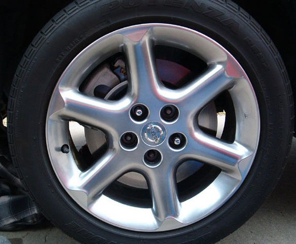
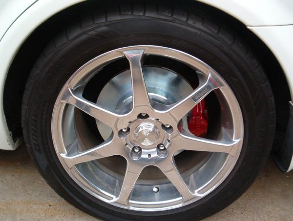
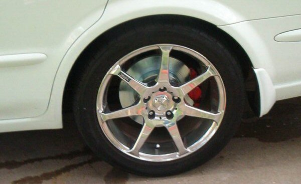
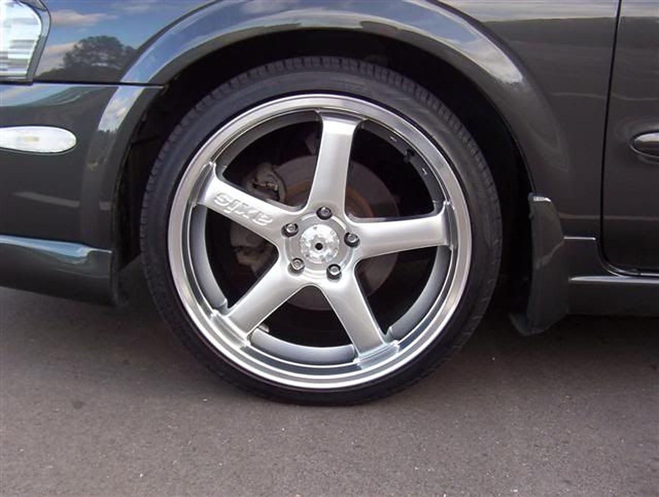
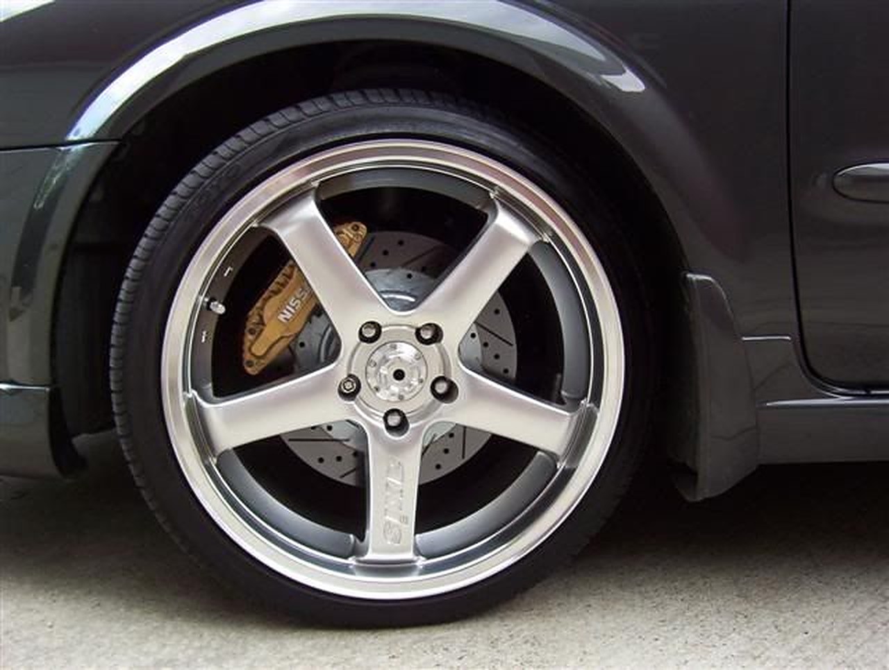
What wheels will these fit under?
I have tried this kit with several wheels so you can get an indication of what will fit…. These kits DO NOT FIT UNDER THE STOCK 17″ Maxima wheels! So far, every aftermarket 17″ and 18″ wheel I have tried will fit, but the 17s get close on spoke clearance–depending on wheel design. I am currently trying to compile a database of all of the wheels that fit these kits to give you an idea, but the best way is to simply measure for yourself. I make no claims to wheel fittment, but for a general guess on if they will fit or not, use these measurements:
Measure 5 1/4″ out from the center of the wheel to one of your spokes. Now measure the distance from the surface of your stock rotors. If you have at least 2 1/2″ of clearance here, then you should be fine with the kit. I can tell you for certain that 300ZX (Z32) wheels will NOT fit without a 1/2″ spacer.
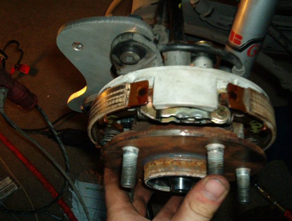
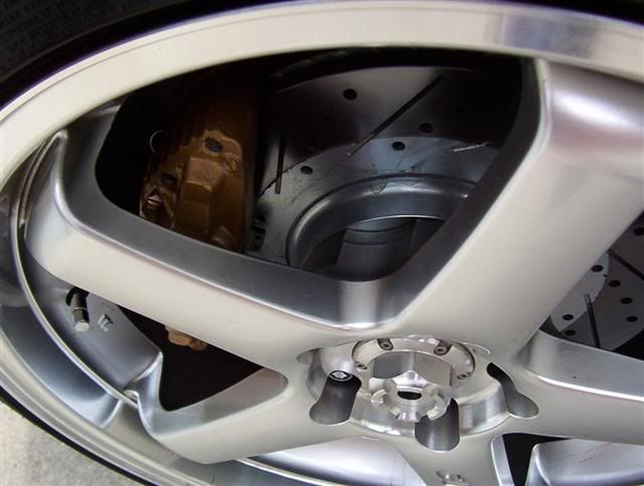
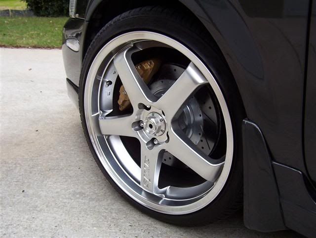
The installed kit:
For those that want to see more up close pics showing caliper clearance around the wheel and spokes, click here
And now for the part you’re really interested in–prices!
Complete Kit: $765 + shipping
This kit is ready to bolt on, with the exception of brake fluid. This kit includes:
Remanufactured 300ZX Calipers
New OEM 2004 Maxima rotors
Custom Stainless Steel Brake lines–these lines are custom made to adapt the 300ZX caliper fittings to the Maxima hard line.
Caliper relocation brackets
All hardware necessary to install the kit
Basic kit: $440 + shipping
Note that this kit does NOT include the required calipers. I can get them if you wish, or you can supply them yourself. This kit includes:
New OEM 2004 Maxima rotors
Custom Stainless Steel Brake lines- These lines are custom made to adapt the 300ZX caliper fittings to the Maxima hard line.
Caliper relocation brackets
All hardware necessary to install the kit
Kit without Rotors: $200 + shipping
This is for those who want to source rotors, calipers, and pads themselves. This kit includes:
Custom Stainless Steel Brake lines–these lines are custom made to adapt the 300ZX caliper fittings to the Maxima hard line.
Caliper relocation brackets
All hardware necessary to install the kit ( again, this kit does not include rotors or calipers )
Want me to source the 300ZX calipers for you? If so, then I can source just about anything you want:
Parts car pulls (cores)–whatever price I can find them. Current prices range from $150 to $250 per set
Cores rebuilt with OEM seal–core price, plus $60 ($30 of which is the rebuild kit). This price does NOT include new hardware. (Contact me if you want new hardware also)
Remanufactured calipers (loaded with generic semi-metallic pads, shims, pins, and hardware)–$350
I can also do powdercoating for $100 per pair on calipers. Please expect a few weeks of lead time if I have to order powder or calipers for you
BlehmCo Maxima Relocation Big Brake Kit
This kit uses easy-to-find, off the shelf ALL Nissan parts! That way the next time you warp a rotor, or wear out the pads at an Auto X, track event, etc…you can just go to the local parts store and pick up replacement parts! Not many BBKs will allow you to do that!
What is this kit designed for?
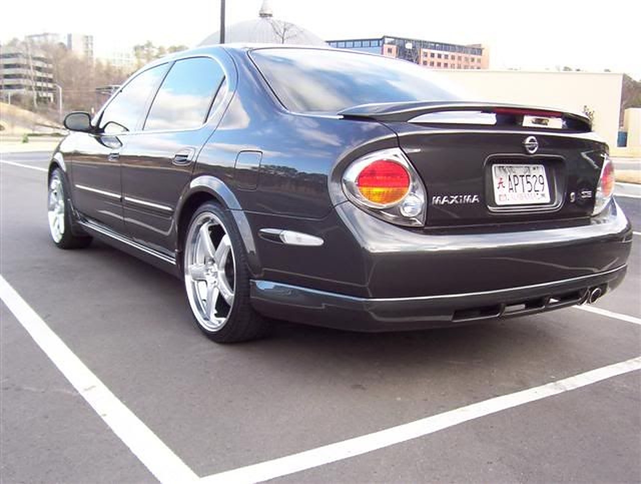
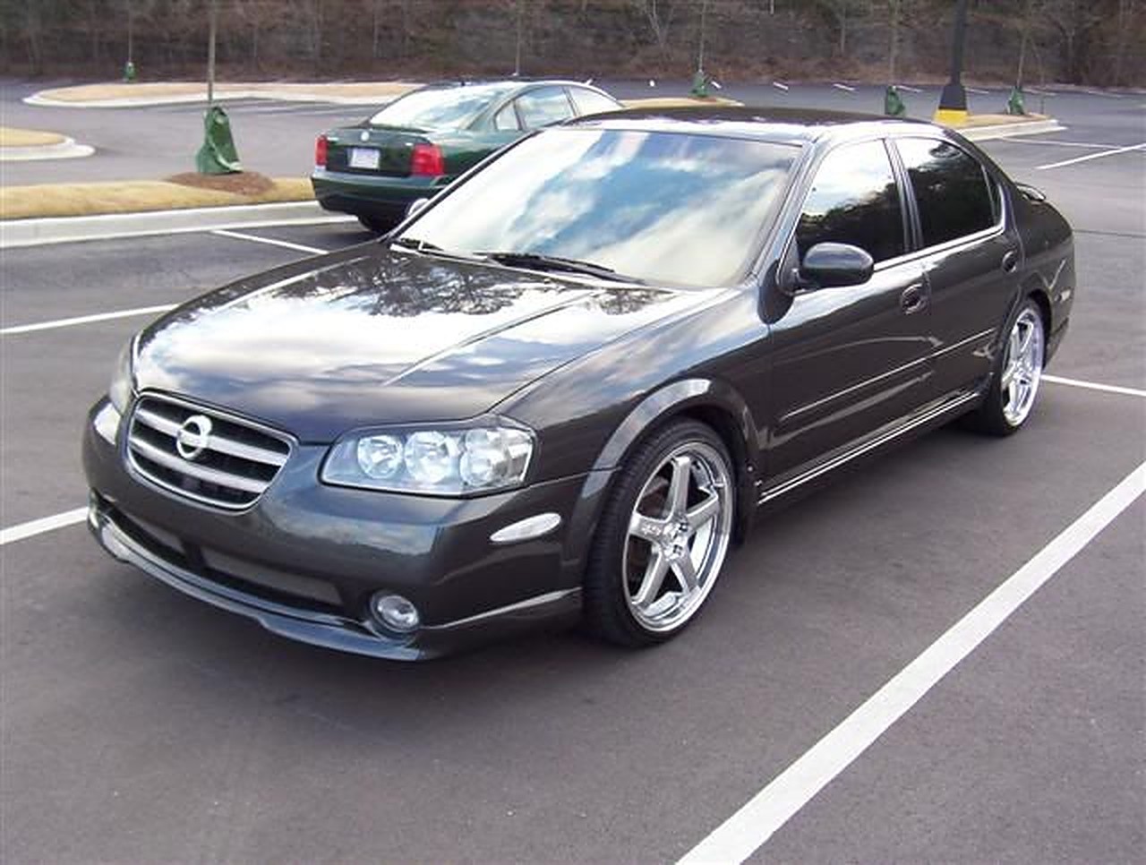
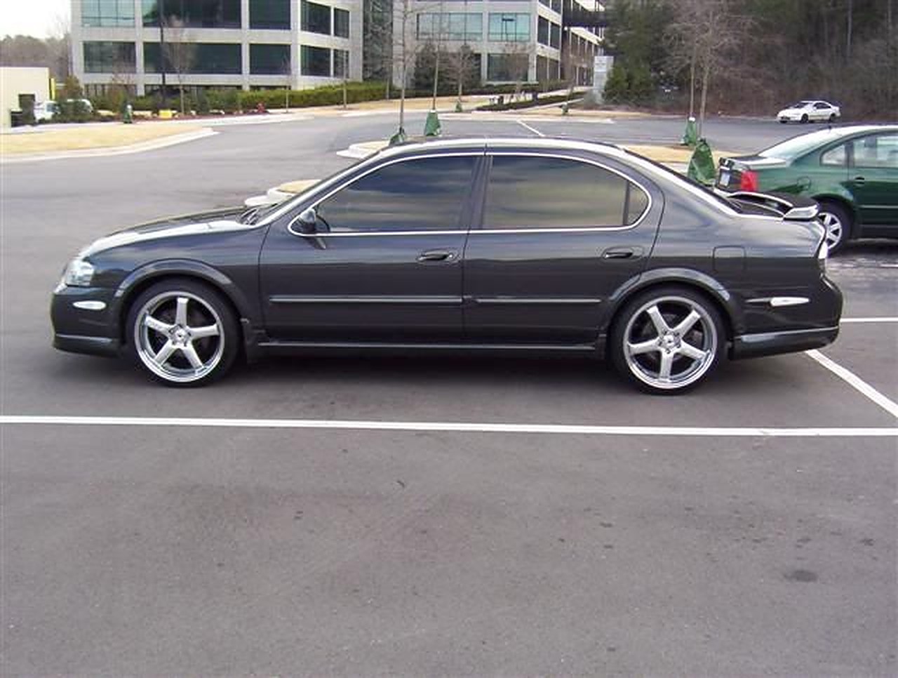
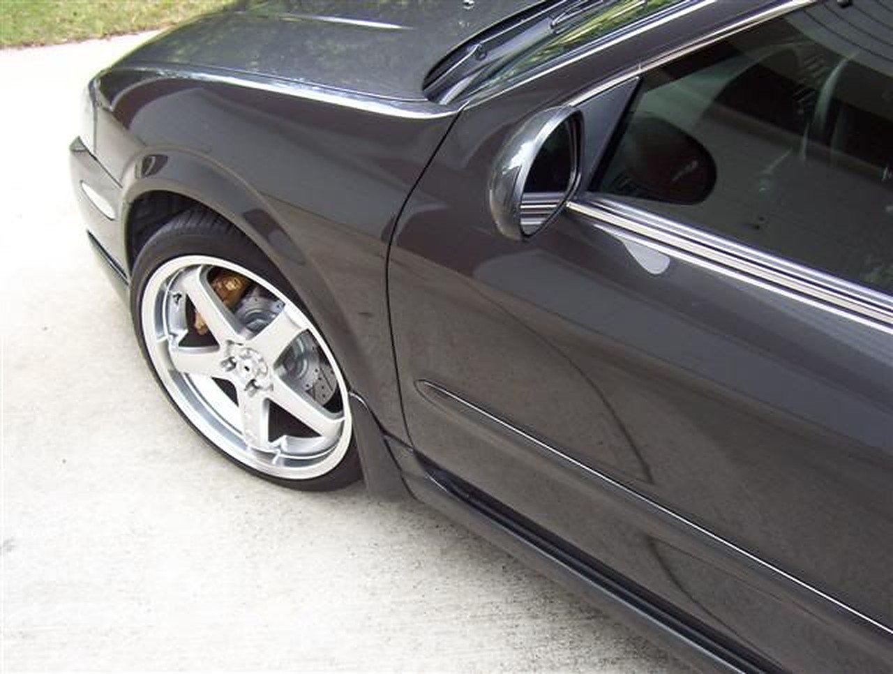
This kit is designed for the average “spirited” driver to alleviate the rotor warpage issues that are so common on 5th Gen Maximas. It’s also an extremely affordable way to improve the cosmetics of your car if you’re running larger wheels. The factory brakes just look too small under 18″ and 19″ wheels! The other goal was to make them fit under the factory 17″ wheels–which this kit does with ease!
Not many BBKs will allow get anywhere near the price of this kit, nor will there be easily available replacement parts when it’s time to replace pads or rotors.
I tried this kit with several wheels, so you can get an indication of what will fit: So far, every 17″ and 18″ wheel I have tried will fit, but the 17s get close on rim clearance–depending on wheel design. I make no claims to wheel fittment, but I would say it’s safe to assume that most 17″ wheels will fit, and sure any 18″ wheel will also.
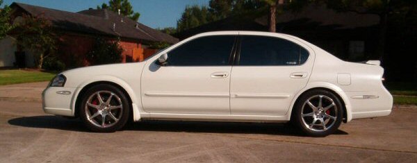
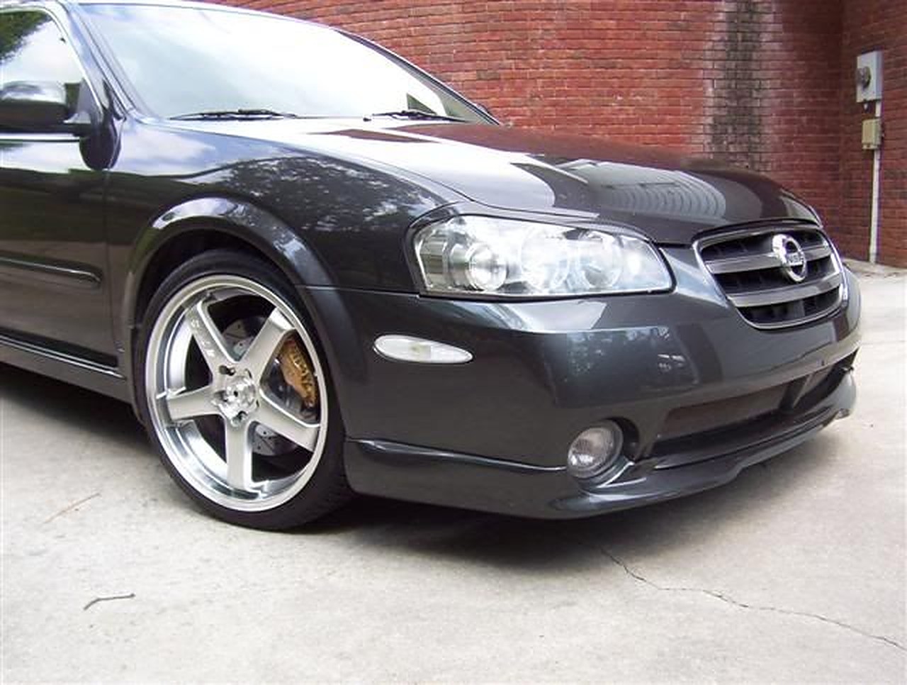
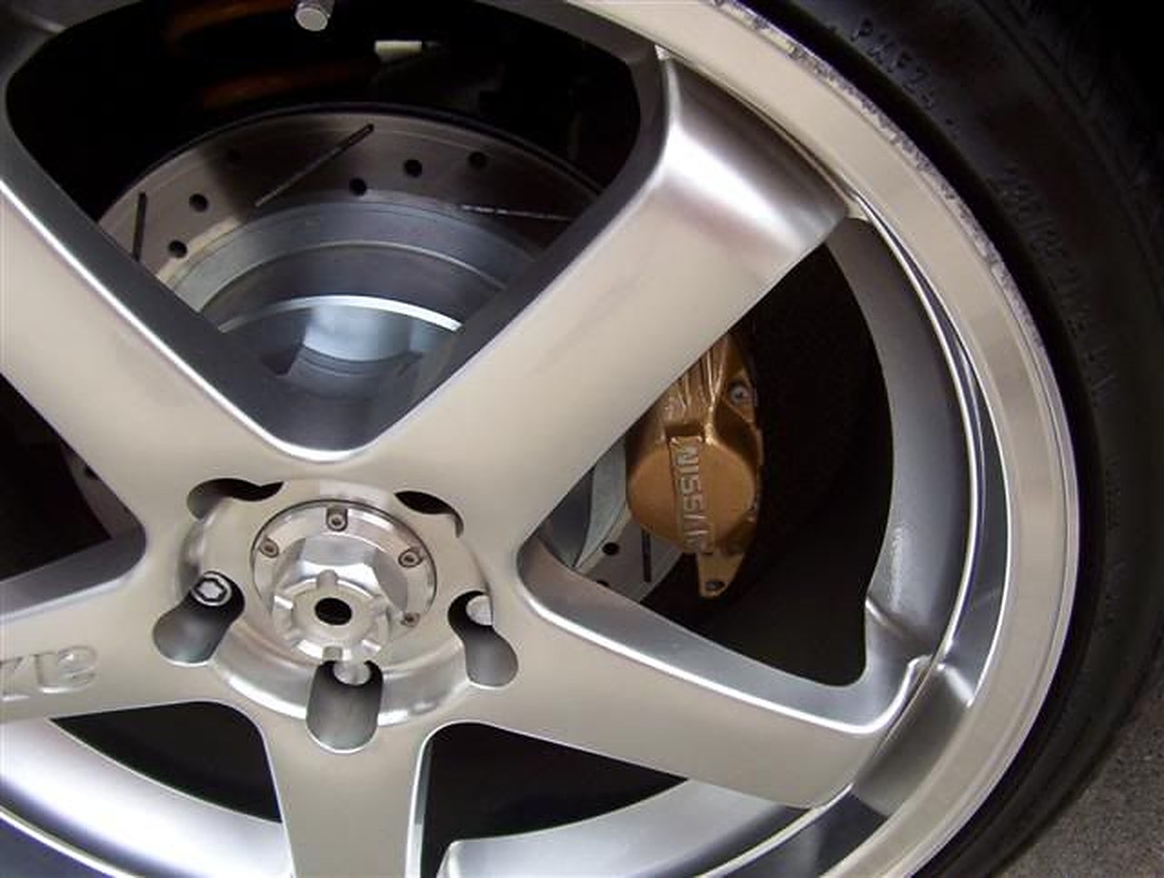
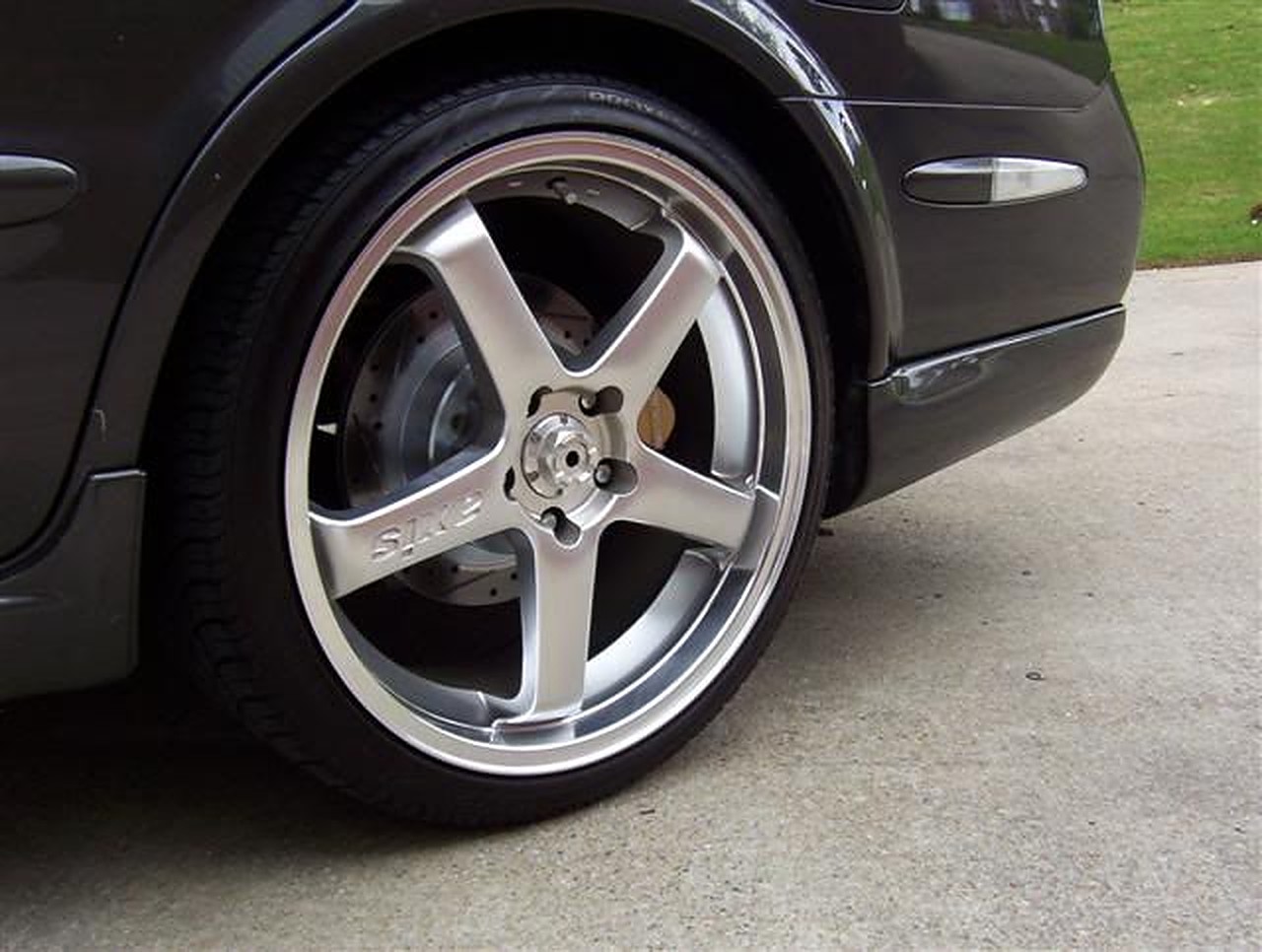
Here are several pictures of the kit, installed on Mike Hill’s gorgeous 2000 Maxima:
And now for the part you’re really interested in–prices!
Ready to Install Kit: $365 + shipping
This includes:
New OEM 2004 Maxima rotors (aftermarket crossdrilled or slotted rotors are now available for an additional $20)
Caliper relocation brackets
All hardware necessary to install the kit (nuts, bolts, & washers)
Complete kit, without rotors: $150 + shipping.
This includes:
Caliper relocation brackets
All hardware necessary to install the kit (nuts, bolts, & washers)
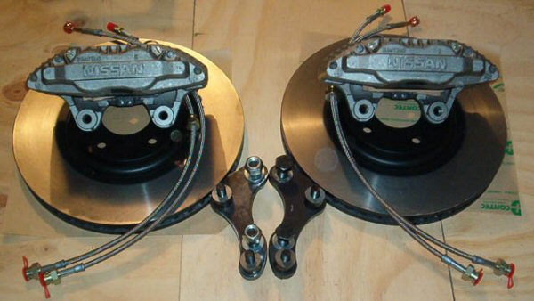
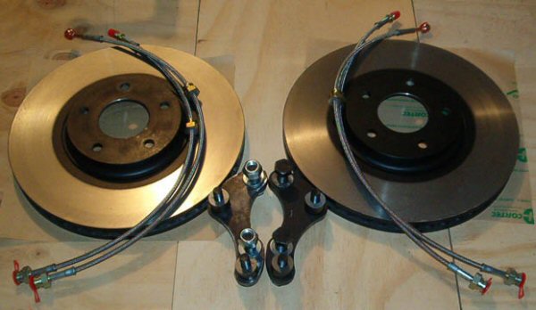
BlehmCo Maxima Big Rear Brake Kit—1995 through 2003 models
This kit uses easy-to-find, off the shelf ALL Nissan parts! That way the next time you warp a rotor, or wear out the pads at an Auto X, track event, etc…you can just go to the local parts store and pick up replacement parts! Not many BBKs will allow you to do that!
What is it?
Z32 300ZX REAR calipers and rotors built to fit 4th and 5th gen Maximas.
What are the benefits to this Rear Big Brake Kit?
You guys already know the benefits of a big brake kit on your car, so I’ll point out the original parts of this kit…
Many of you that have purchased Big Brake Kits for the front notice a front brake bias problem now. This is safer than having a large rear bias, but it is not the best performing. The rear brakes are tiny and just aren’t up to the task once you’ve upgraded the front brake system. They also look like go kart brakes behind the larger 17″,18″,and 19″ wheels that many owners are using now!
This kit, when paired with most front brake kits, will return the brake bias to within 3% of the factory front/rear bias. In my experiences, this has provided the best overall braking–nearly zero nose dive when you’re on the brakes hard, but you can still brake into corners without locking up the back end.
As most of you know, the 300ZX calipers have a plethora of pad selections out there–WAY more than the Maxima does because of the performance enthusiast base. You can go with Raybestos, Wagner, Axxis, or comparable pads for the street for a very reasonable price, or you can bump up to Hawk, Performance Friction, Porterfield, Ferodo, EBC, and many other higher performance pads for track days. If you’re in a pinch and need new pads “NOW!”, simply drive to your nearest parts store and pick some up! They’re extremely handy, as opposed to other aftermarket calipers where you usually have to order pads and wait weeks for them to come in! These calipers are also designed for street use in that they have dust seals, pad shims to keep road noise to a minimum, easily obtainable rebuild kits, and all the other low maintenance benefits of a caliper designed for years of street use instead of a caliper designed to be rebuilt several times per race season.
You can also purchase rotors at just about any aftermarket or OEM dealer. They have a huge selection of finish, slotting and drilling, and cryo treating options.
How?
For those of you that are familiar with the Z32 brakes, they use an internal drum-type parking brake–as almost all other high performance brake systems do now. This makes caliper maintenance and pad changes extremely quick and easy, but this is also what makes designing a rear brake kit for this car very challenging. I have designed and built a rear drum-type parking brake to fit inside the Z32 rotor, and that’s what this kit is based upon.
Will this work with front Big Brake Kits from another company?
Some of the other kits out there (Stillen, Fastbrakes, Precision, etc) use different piston sizes in their calipers that will affect brake bias considerably. Please check with me before purchasing and be ready to do some measuring of your calipers (or have the part numbers ready for the calipers so I can look them up.) I have talked with Fastbrakes and confirmed the piston sizes on their calipers–their systems will work wonderfully with my rear BBK. I have yet to confirm this with other kits.
If you buy this kit for other front systems, the worst you will have to do is install a $50 brake bias adjuster from Wilwood or Tilton to make this kit run on your car. Simply be very careful about locking up the rear brakes until you have adjusted the bias to fit your system.
How Much does it cost, and what do I need?
I have set the price on my parts so that the entire setup should cost you under $1000 for everything needed to install the kit on the car. I will send you everything needed EXCEPT rear calipers, rotors, and brake fluid, which you will be able to purchase from the sources below and come out under $1000 total.
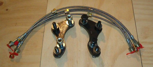
The parts I will supply are the parking brake assemblies (including custom backing plate and bracket), replacement parking brake cables (your original cables will not work), 6061 aluminum caliper relocation bracket, all fasteners and hardware required for installation, and custom rear DOT approved stainless steel brake lines made to fit this setup.
The parts you need to supply are 300ZX rotors and calipers, pads, and brake fluid. Rotors: Feel free to purchase them from any place you like, but I highly recommend IRotors.com You will need to purchase a pair of REAR rotors from a 1990-1996 300ZX.
Calipers: You can find them quite often on Ebay for under $100 a pair. Any 1990-1996 300ZX TT or N/A rear calipers will work–they’re all the same. If you purchase them used, I highly suggest rebuilding them. You can buy a rebuild kit from Orielly’s Auto Parts, Pep Boys, Autozone, etc for under $10. Many auto parts stores also carry remanufactured calipers for a reasonable cost. In Houston, they are about $100 each without core, $60 each with core.
Now for some Pics!
So what’s the total price from BlehmCo?
You will send me $720 plus shipping for the parts you need from me. Shipping usually runs about $20 for anyone in the main 48 states. CA, AK, and HI are more, but I am more than happy to ship worlwide! You will still need to purchase rotors, calipers, pads, and fluid. This should run you less than $250, which puts you at just under $1000 for the entire rear brake kit!
I can also do powdercoating for $100 per pair on calipers. Please expect a few weeks of lead time if I have to order powder or calipers for you.
As for stopping power, it’s a hell of a lot better than stock. It’s a lot smoother and you can actually feel the brakes grip. There is a little roar when braking hard because of the slots and holes in the rotors rubbing on the pads.
Pedal feel is a little softer, but you get used to it. I went from a stock brake system of 4 pistons total in the calipers to 12 pistons. There is more fluid to push so yeah…. expect a softer pedal if you’re going to use the stock brake booster.
The new e-brake that has to be used with the 300zx rear brakes isn’t as good as our stock e-brake but works okay. The lever is a lot firmer and you really have to pull it up to hold the car on a hill.


")

 Remove ECU cover from passenger side footwell.
 Loosen bolt in the center of the main ECU connector using your 12 mm Socket / Socket Wrench and Extension.


")