Category

External-Affiliate

Category

Original Source Credit: http://www.nisformance.com/Articles.asp?ID=252

This article shows how to swap a 2007+ Altima 3.5L VQ35 engine, or 2009+ Maxima 3.5L engine into older Nissan Maxima’s. Including the 2002-2006 Altima (3.5L) and 2002-2008 Maxima’s. This motor swap is referred to as the 2nd Generation (Gen2/Gen3) VQ35DE swap.

NISformance Swap Kit

  • This kit allows you to install a 2nd generation or 3rd generation VQ35DE engine into a 2002-2008 Maxima or 2002-2006 Altima (3.5 V6)
  • The NISformance 2nd Generation VQ35DE swap kit consist of four main components. (2) Cam sensor signal inverters, a plug and play throttle body adapter harness, a belt tensioner bracket, and an alternator bracket. Each component and its intended use is detailed below.
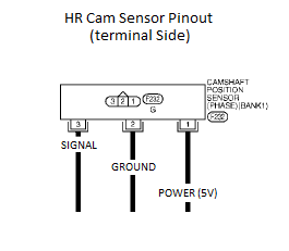
  • Camshaft sensor signal inverters – Allow the stock harness to be attached to a newer 2nd generation motor and intercept the camshaft signal wires. This is an essential part of the swap kit and has been designed with ease of install in mind. Each inverter comes with a camshaft sensor plug attached. Wiring necessary consist of three wires. Ground, Power, and Signal. These new inverters are single channel. One inverter is required for each camshaft position sensor.
  • Throttle body adapter harness – Necessary in order to utilize the 70 or 75 millimeter throttle body that is equipped on 2nd generation motors.
  • Belt tensioner and alternator brackets – Needed in order to use stock alternator and belt tensioner. Zinc coated for high corrosion resistance and added clean look.

VQ35DE Engine

There are three generations of the front wheel drive VQ35DE engine.

  • The first generation VQ35DE was used by Nissan in many front wheel drive applications. Ranging from the Maxima to the Quest minivan.
  • Second generation engines were used in the 2009+ Maxima , and 2007+ 3.5L Altima as well as a few other front wheel drive applications as before. The second generation VQ35DE engine is equipped with “HR” heads allowing for increased air flow and improved performance. Oil consumption and other flaws commonly found in first generation motors have also been addressed.
  • There are also two variations of the 2nd Gen VQ35DE engine. A Maxima engine is equipped with EVT ( Exhaust Valve Timing ) and has a slightly higher compression ratio along with larger intake manifold and throttle body (75mm). The Altima engine has a slightly lower compression ratio, and is not equipped with EVT. The intake manifold and throttle body (70mm) are also a bit smaller.
  • There is now a third generation of the front wheel drive VQ35DE. This engine is found mostly in the 2016+ Nissan Maxima. This engine can be used for this swap, with the only difference being the TB pin out. We offer the correct TB adapter harness for this newer TB as an option for our swap kit.

Required and recommended items:

2nd Generation VQ35DE Swap Kit ($230.00)

Order Link: http://www.nisformance.com/2nd-3rd-Gen-VQ35DE-swap-kit-p/hrkitv2.htm

EPS Tuning Oil Gallery Gasket/Hardware Kit 2nd Generation VQ35DE engine ($60.00)

Order Link: http://www.nisformance.com/EPS-Tuning-Oil-Gallery-Gasket-Hardware-Kit-p/oilgallerykitfwdhr.htm

There are a few things to keep in mind before beginning your swap:

  • It’s easier to do this swap if you have a 3.5 DE motor laying around, especially if you just pulled it out of the car. You will need to take some things off of the old motor to use on the HR. Without this, there are a few parts that you will have to purchase in order to complete the swap.
  • Keep in mind, you are swapping the “long block” with intake manifold only. You will need to re use a lot of your existing accessories or parts specific to your car. This also includes wiring and harnesses, sub harnesses ect..
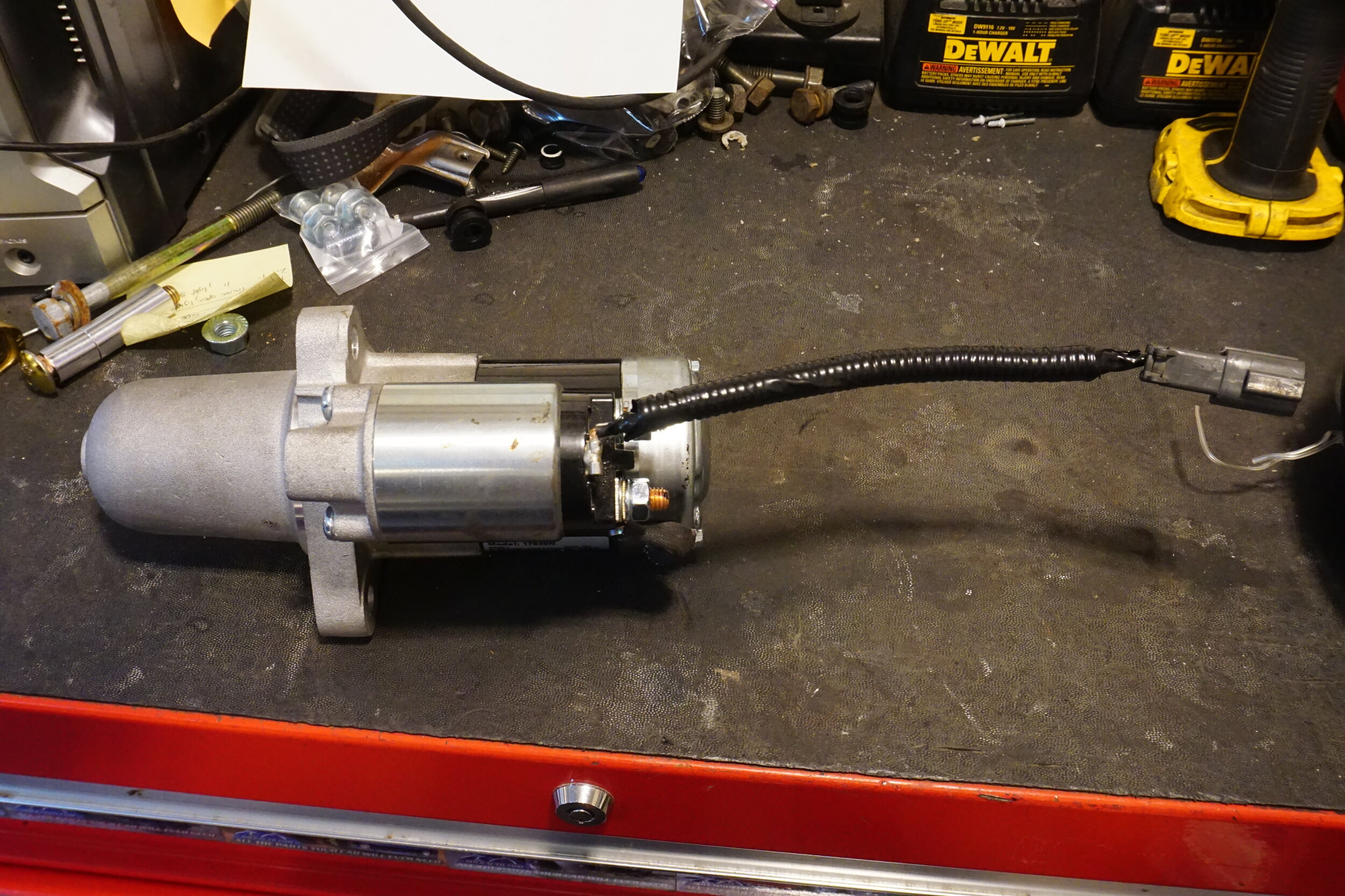
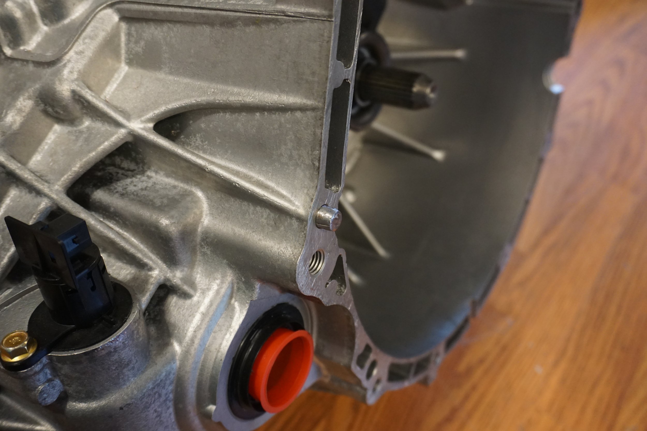
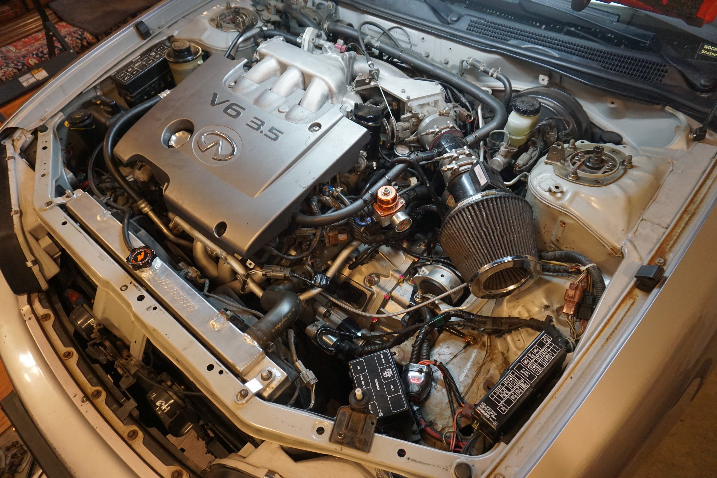
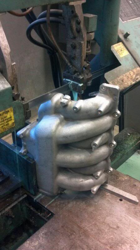
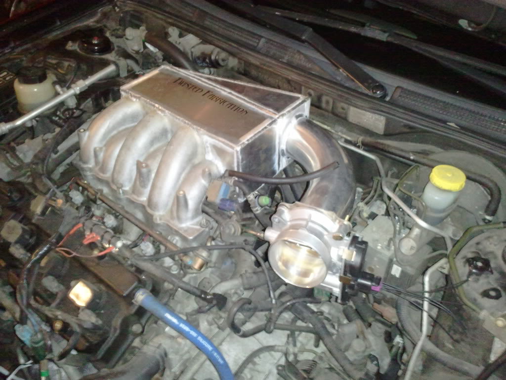
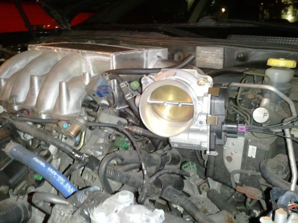
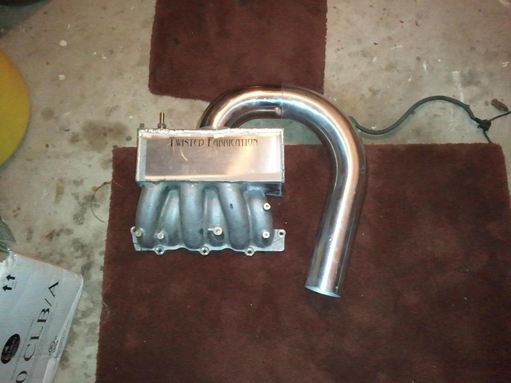
  • Picture below is what your prepped “2nd Gen” or “3rd Gen” engine should look like prior to going into your car.
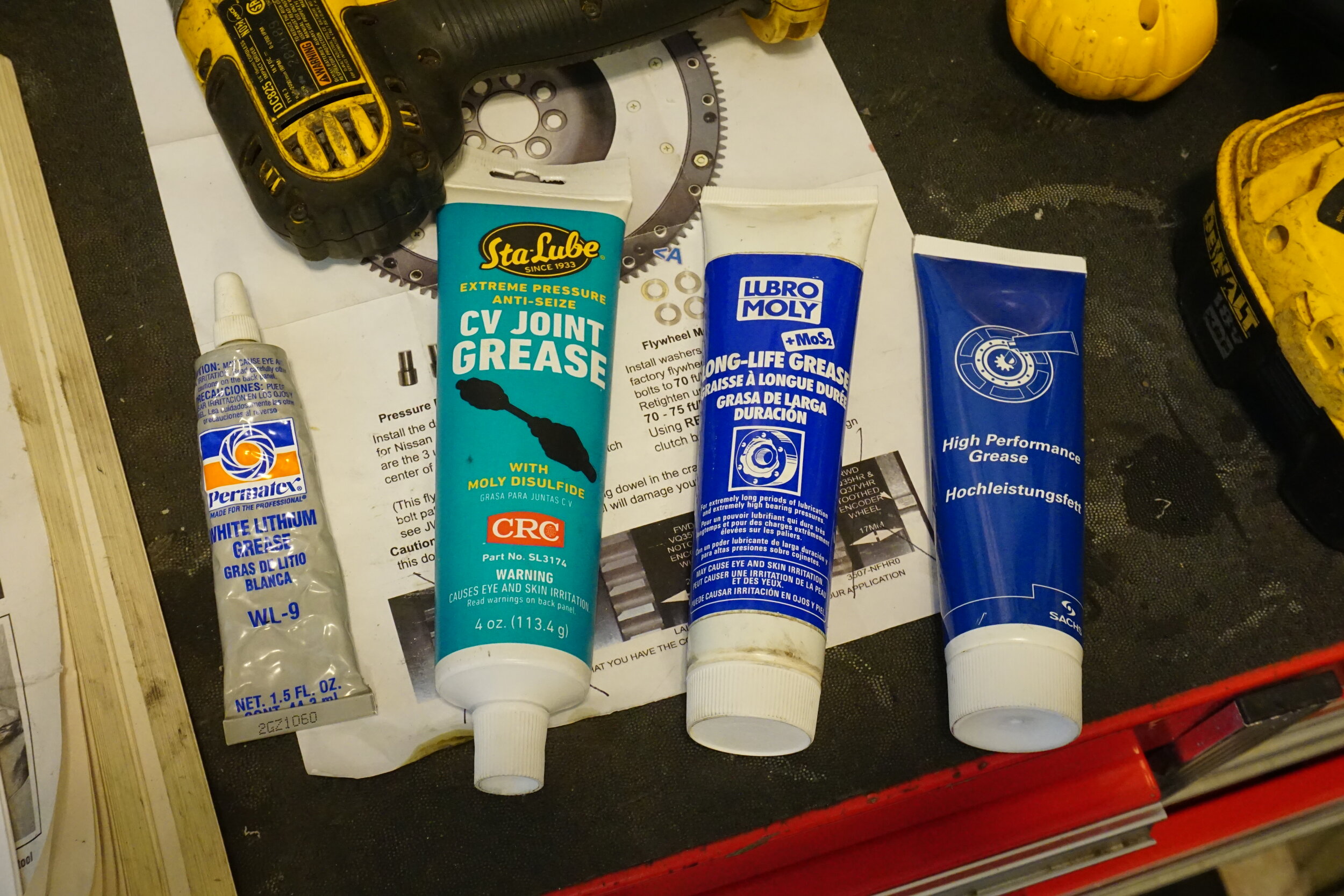
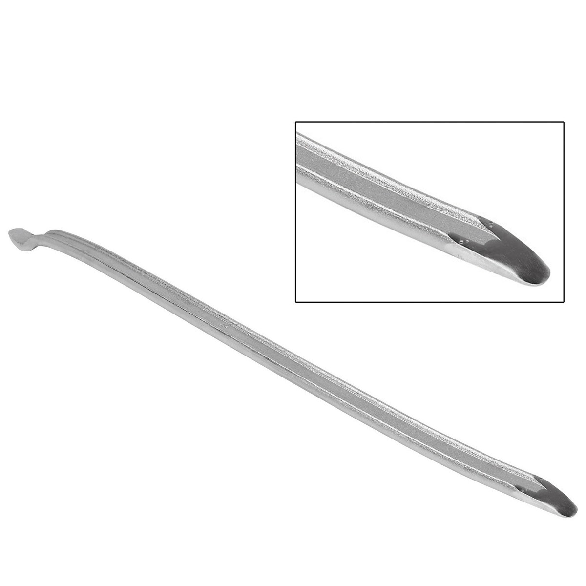
    There are some specific tools needed: An ‘E8’ torx socket, 5/16 Allen key, Loctite

Stripping the motor

Depending on where your motor came from, there may be a lot of ‘extra’ pieces still attached to it. Some of these will just get in your way while you prep your motor, some can’t be used for this swap.

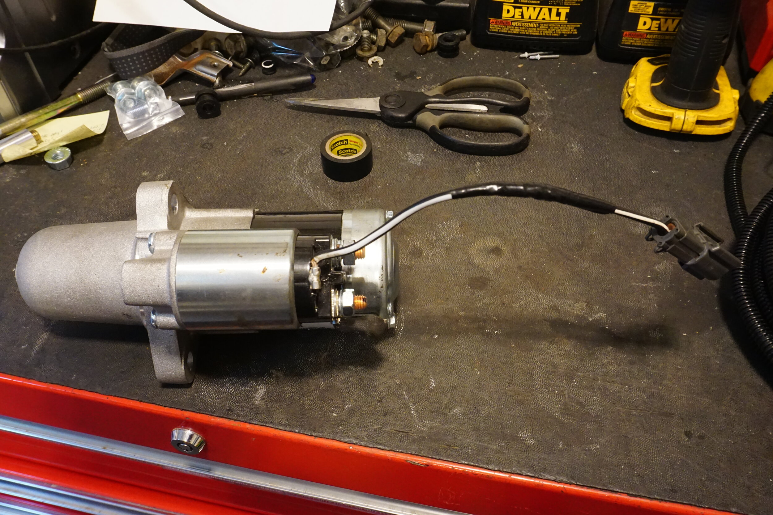
  • Remove all accessories, which includes the alternator, power steering pump.
  • Remove any harnesses and brackets that are still connected to the motor.
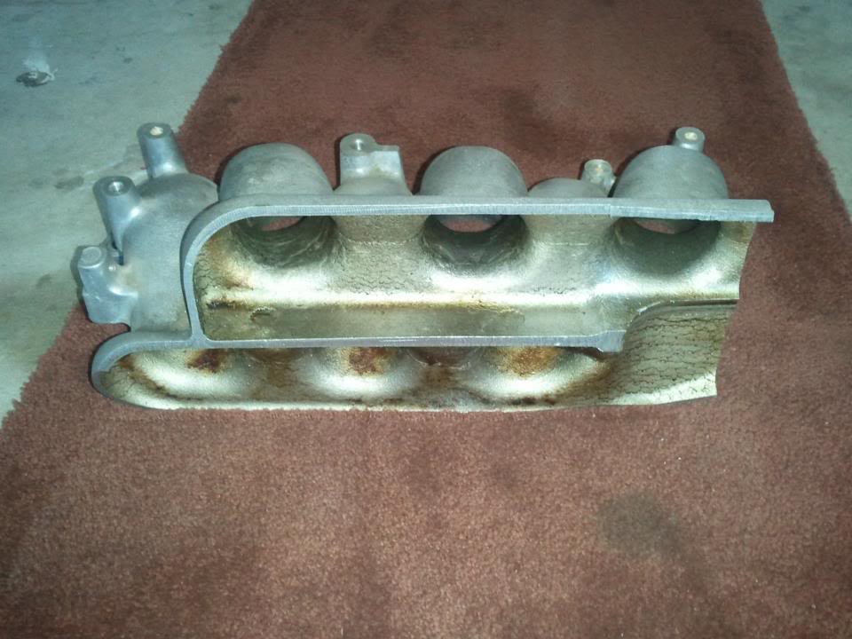
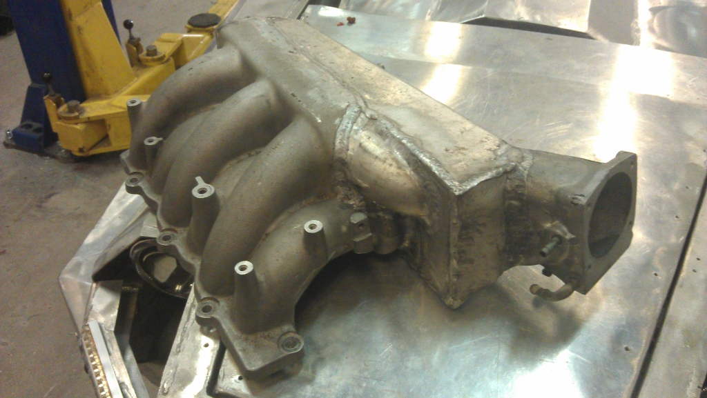
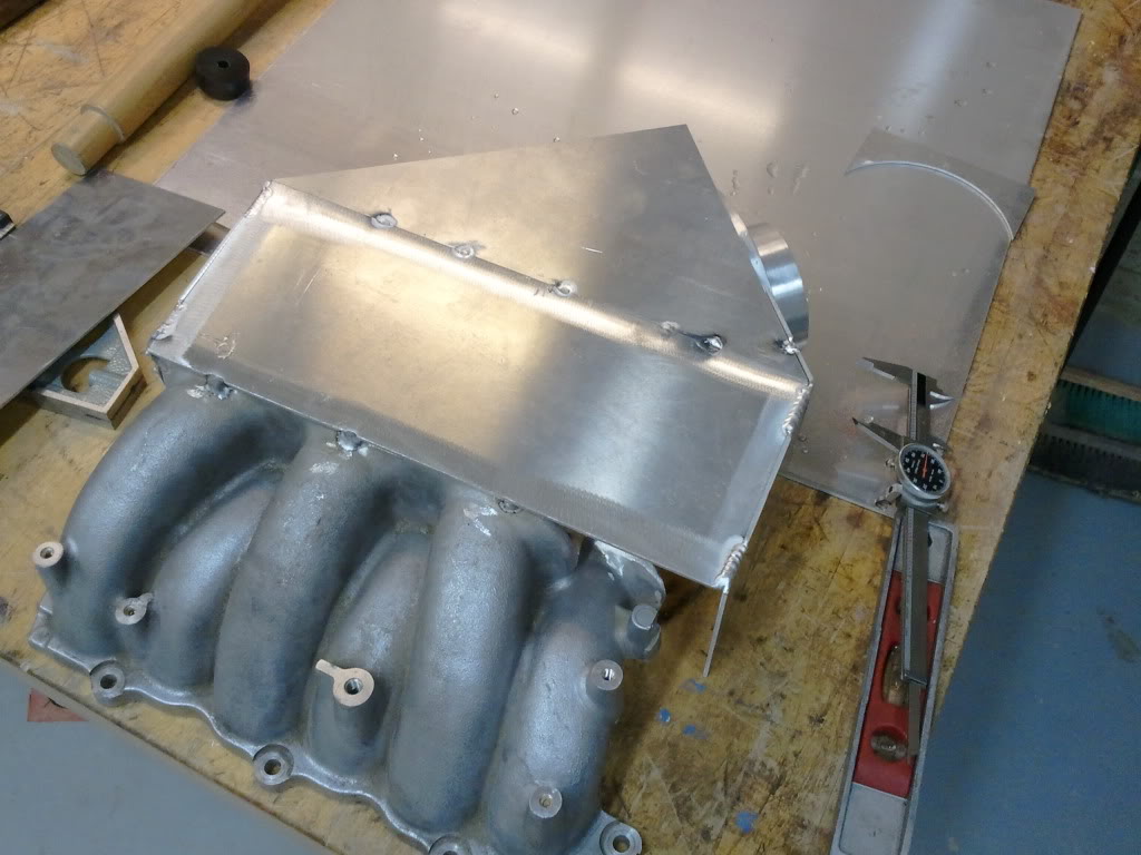
  • Remove upper intake manifold (removing lower manifold is not necessary, but sometimes desirable. If removed, a new gasket should be used to reinstall).
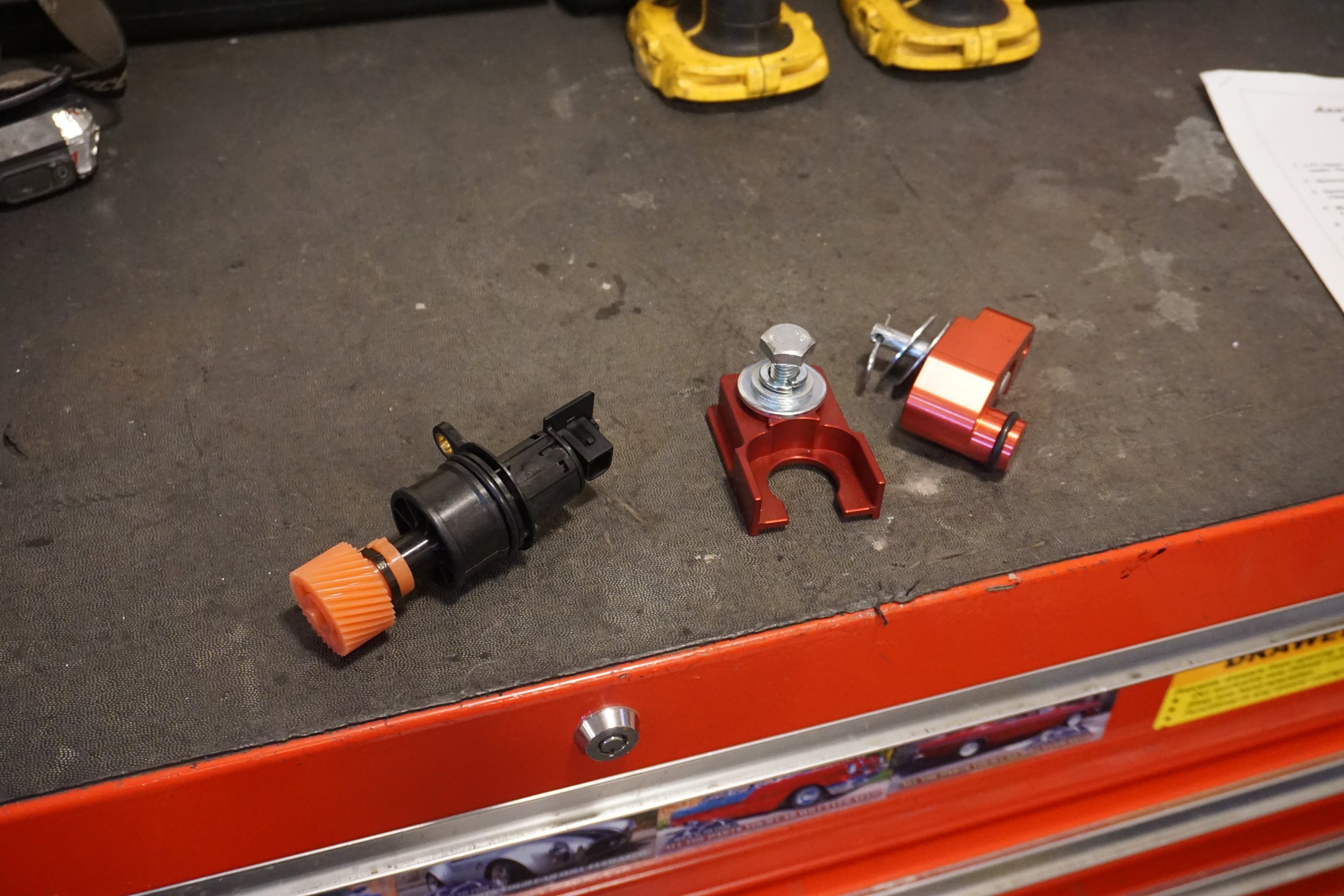
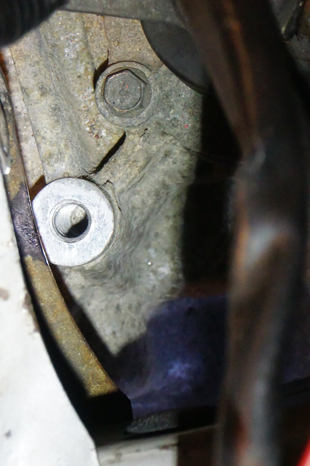
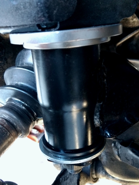
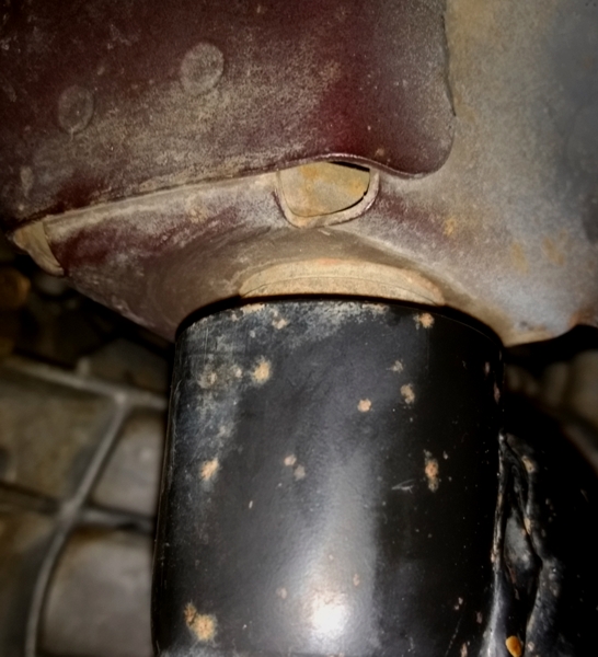
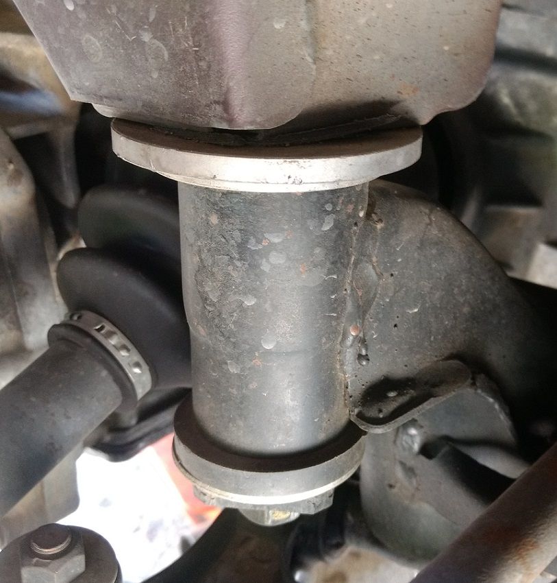
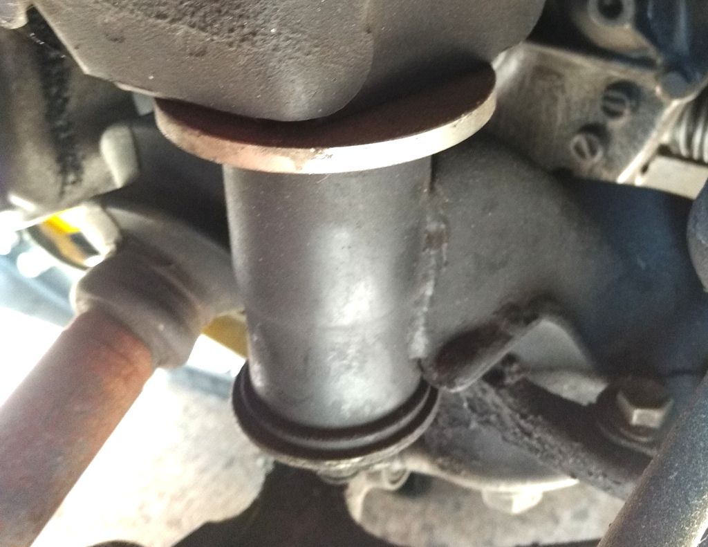
  • Remove oil temperature sender:
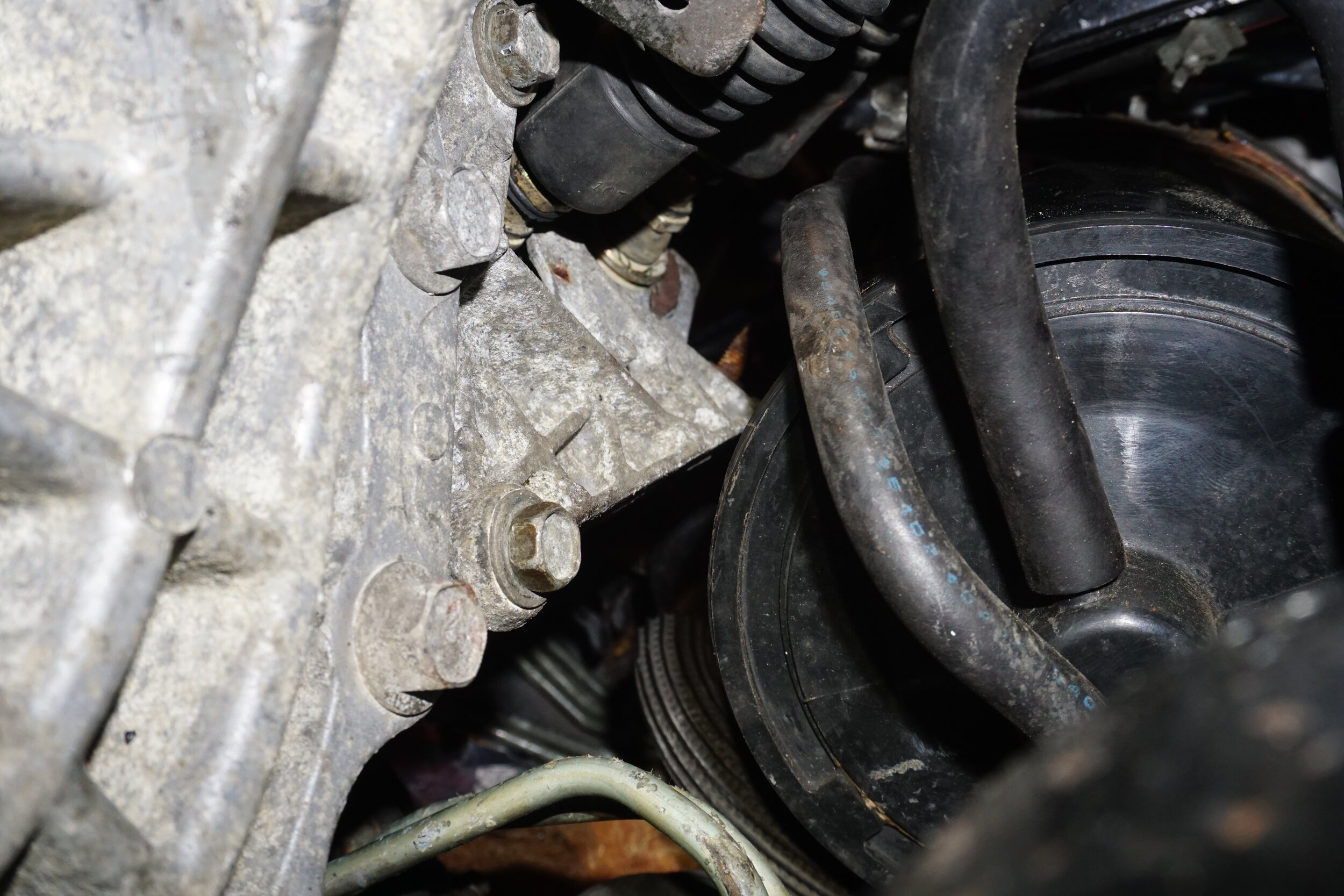
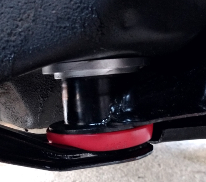
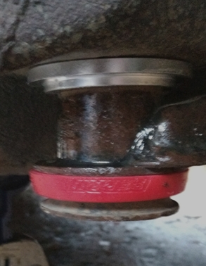
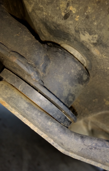
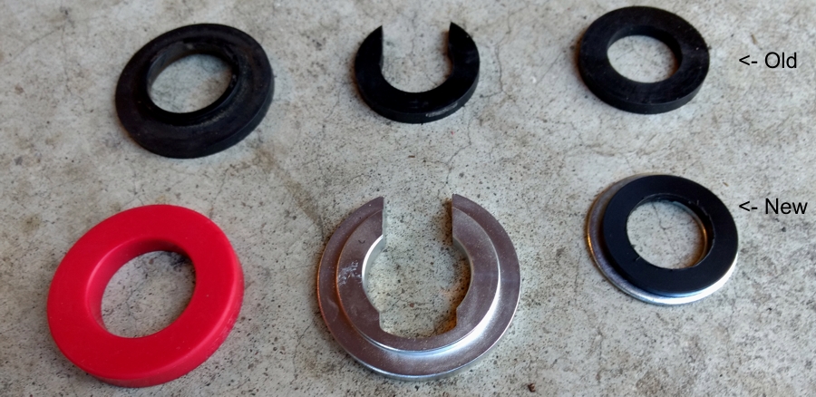
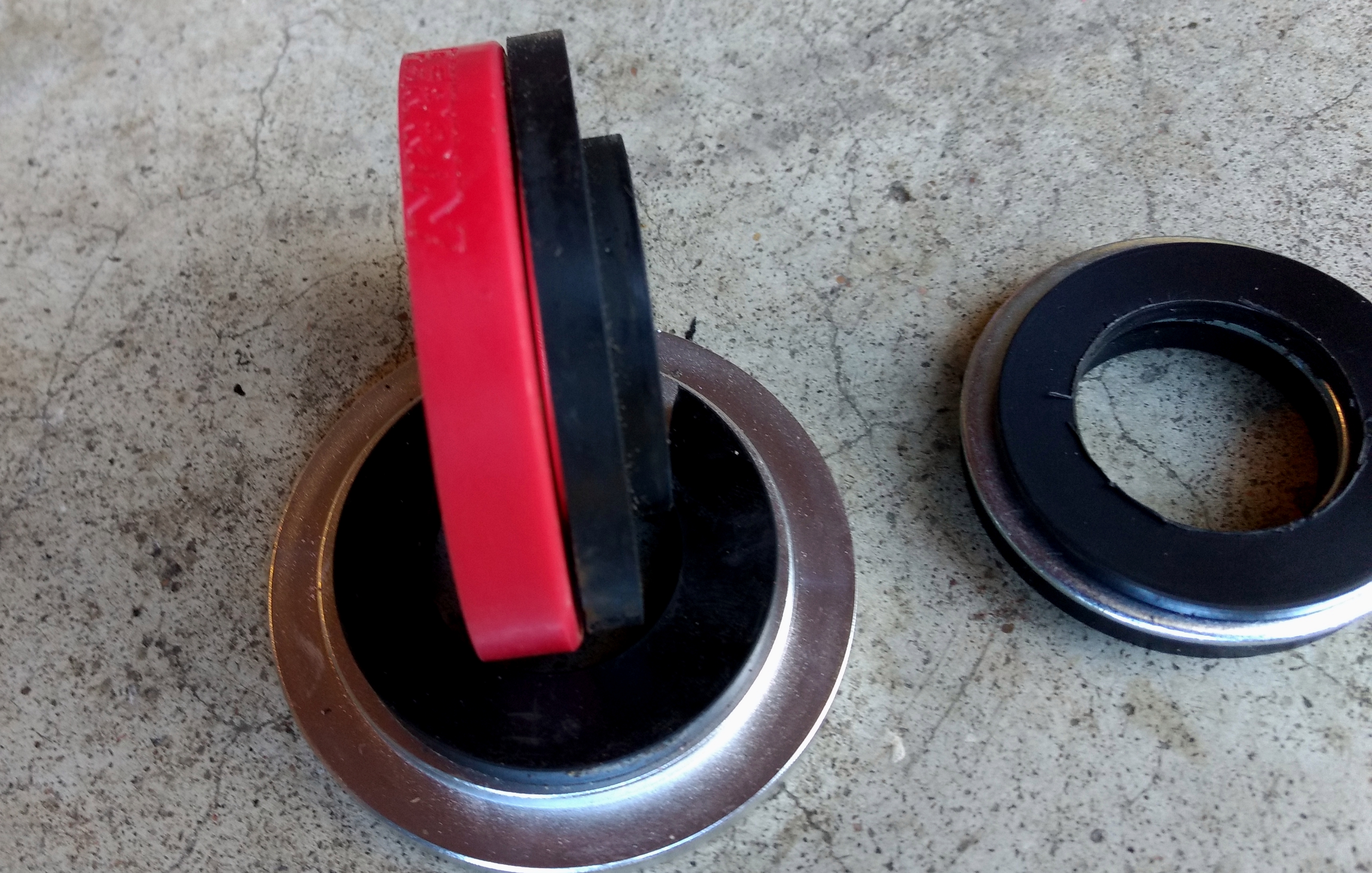
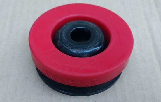
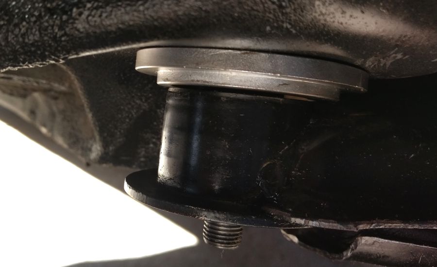
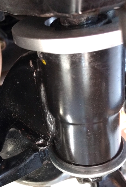
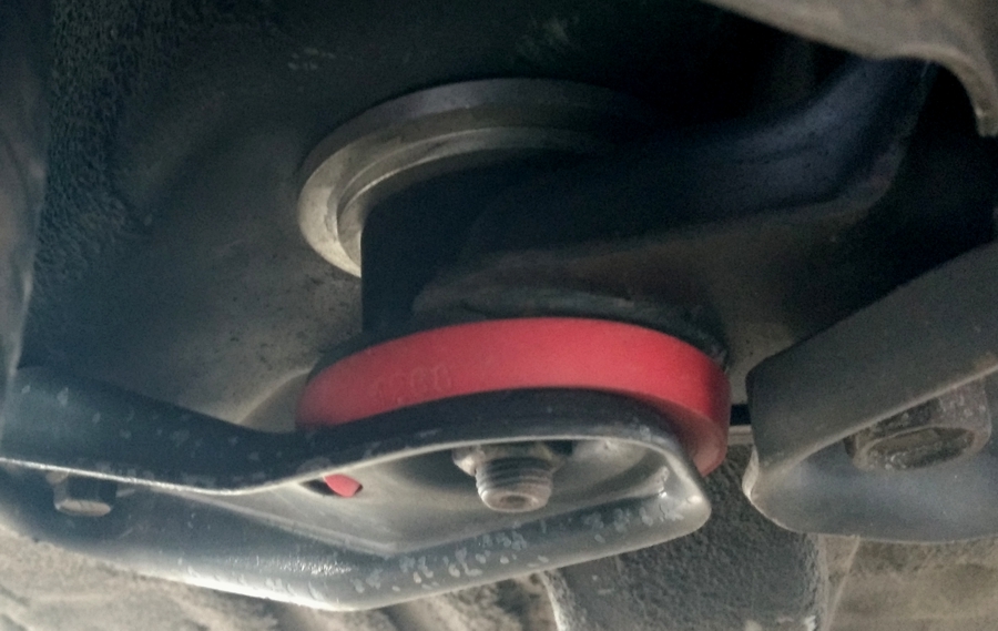
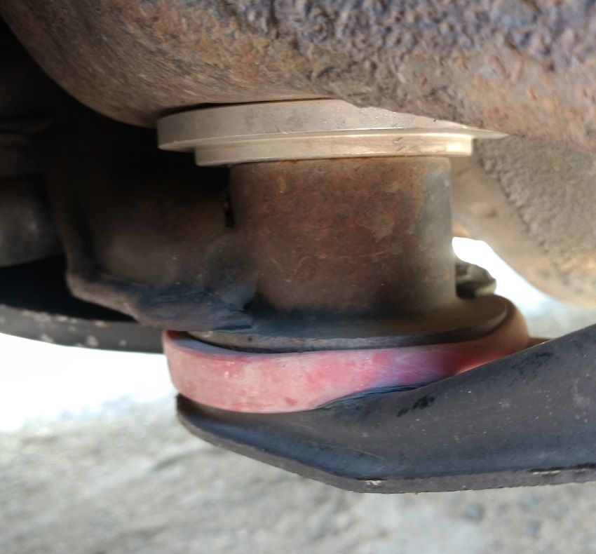
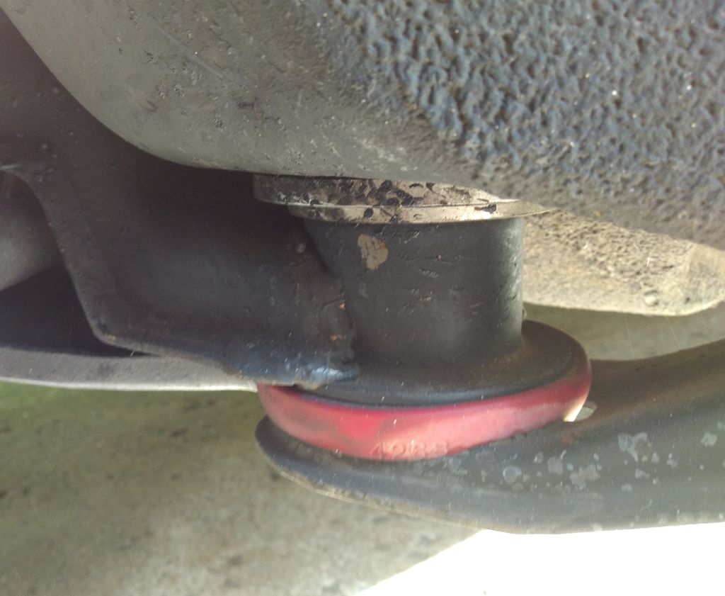
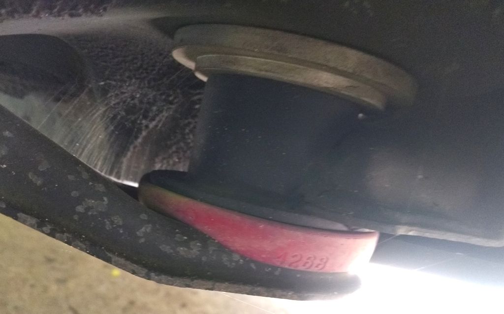
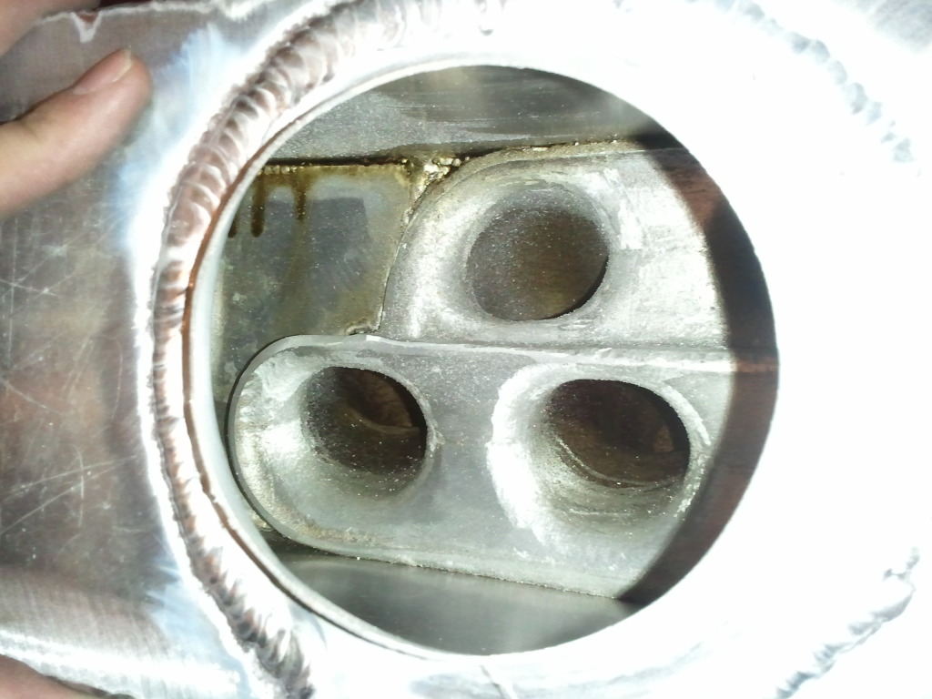
  • Remove idler pulley/tensioner ‘spacer’ (seen below in red):
    ** The injector rail may also be removed, but that isn’t necessary.

Modifying the Motor

Some parts of the motor will need to be cut somehow (tools, methods and results will vary) to allow for proper fitment and function once it’s reinstalled.

** Because of some concerns about the integrity of the stock oil gallery gasket, we at NISformance strongly recommend replacing it in this step. **

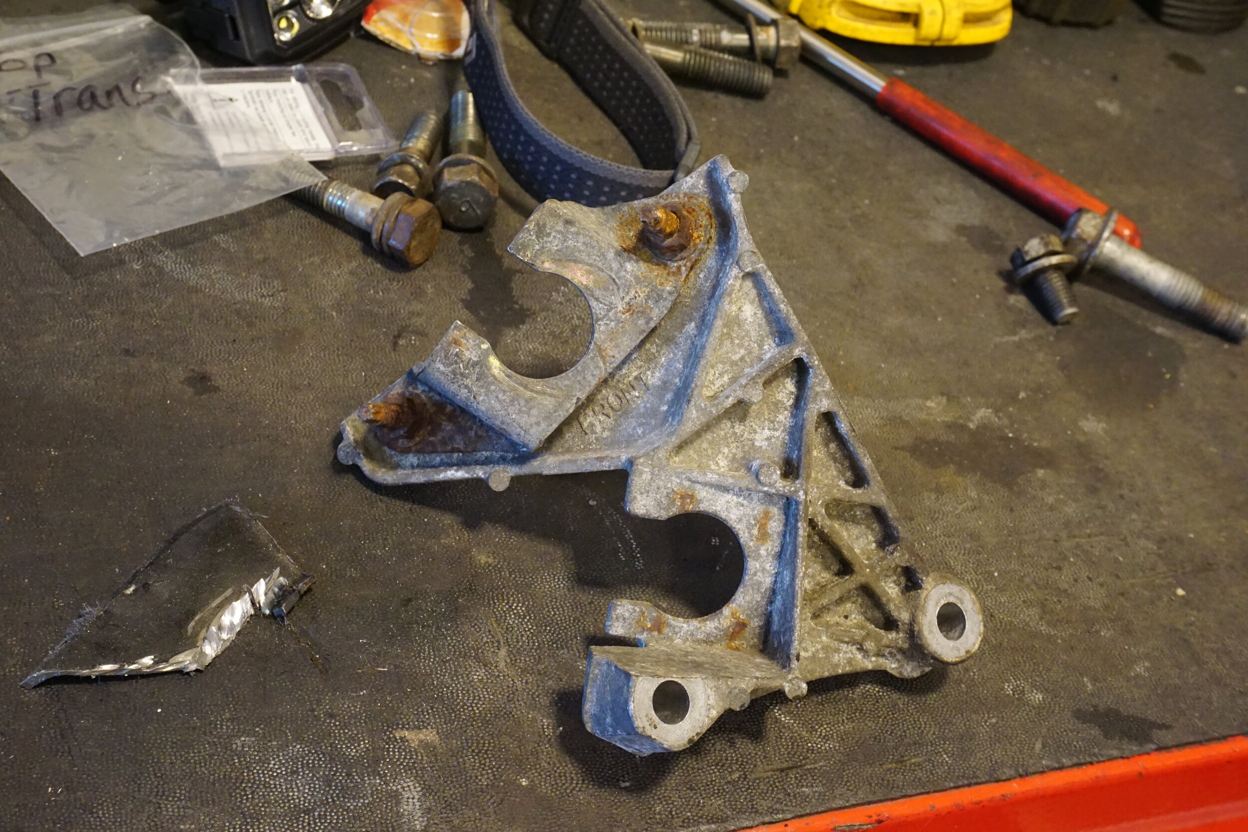
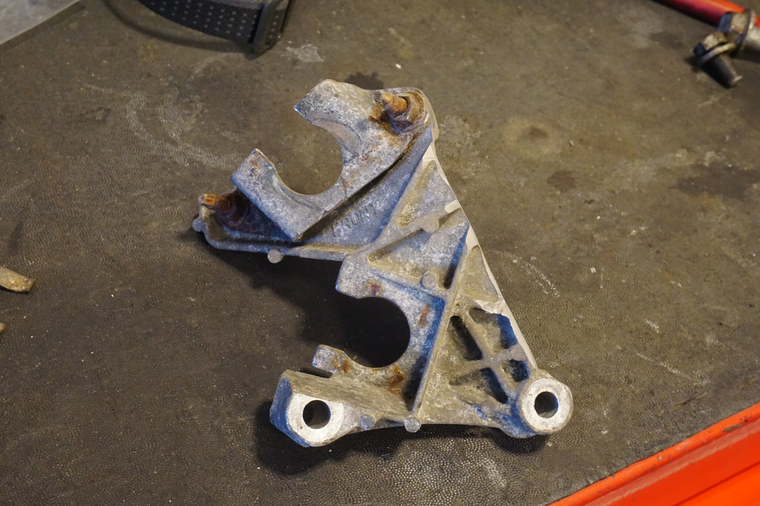
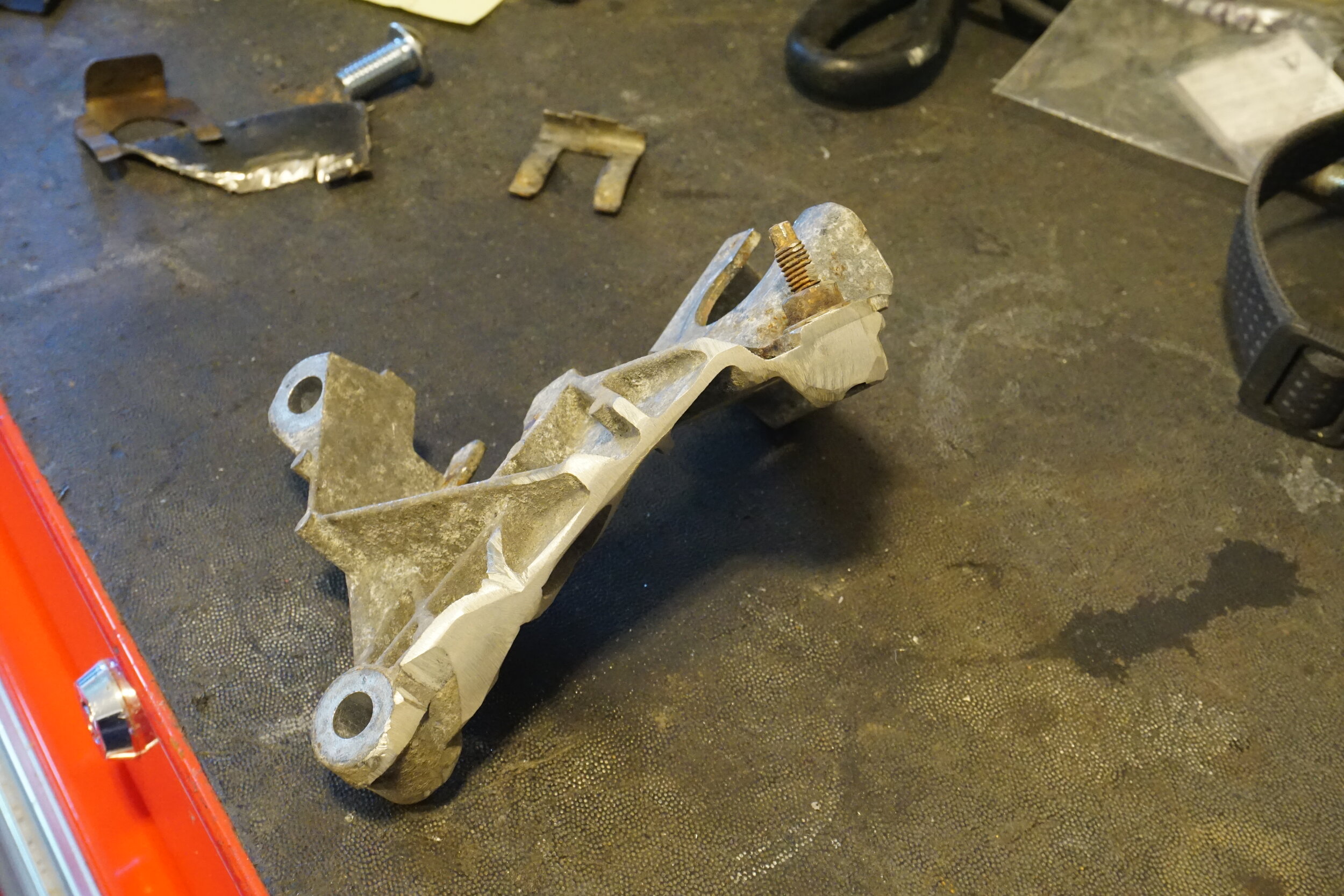
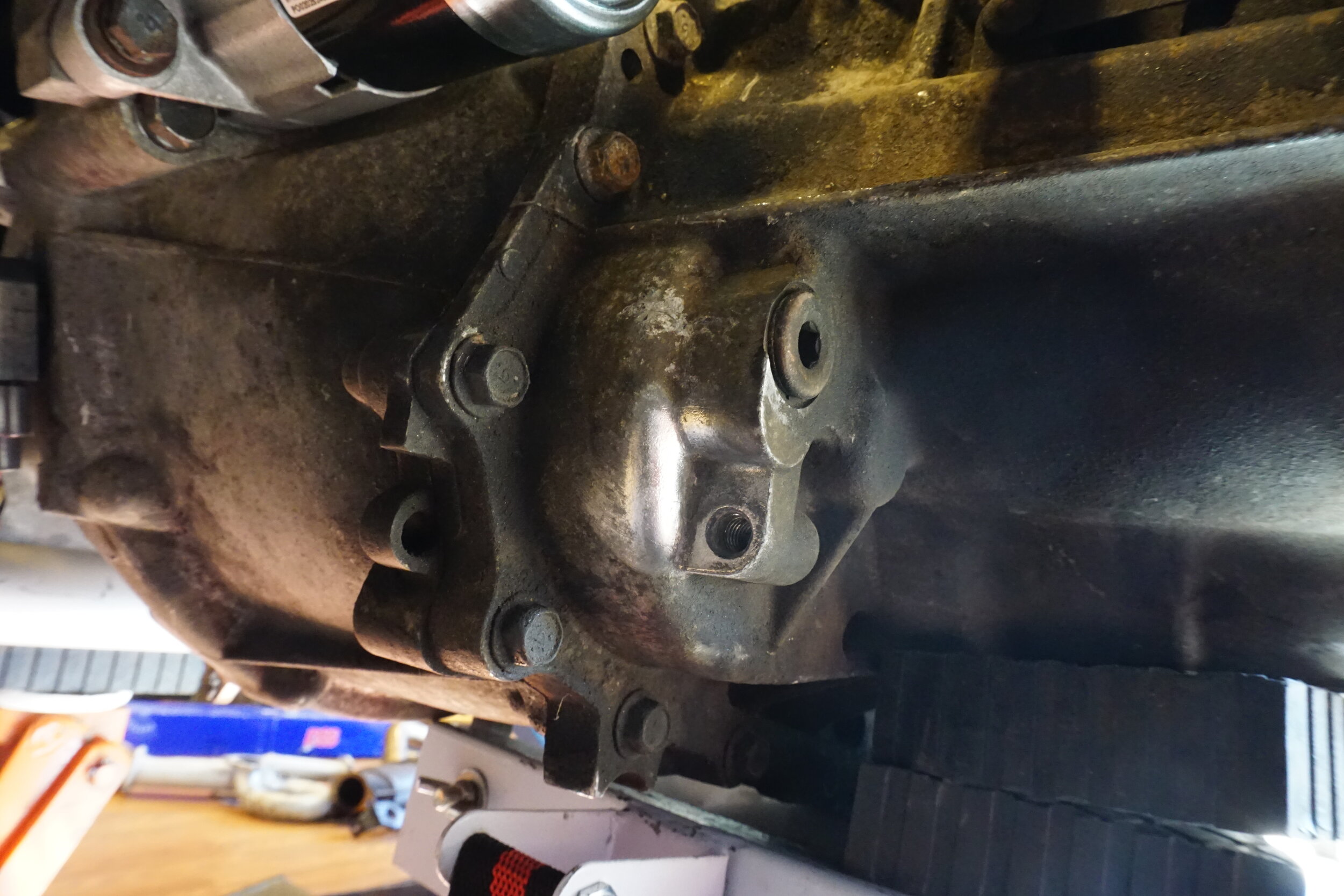
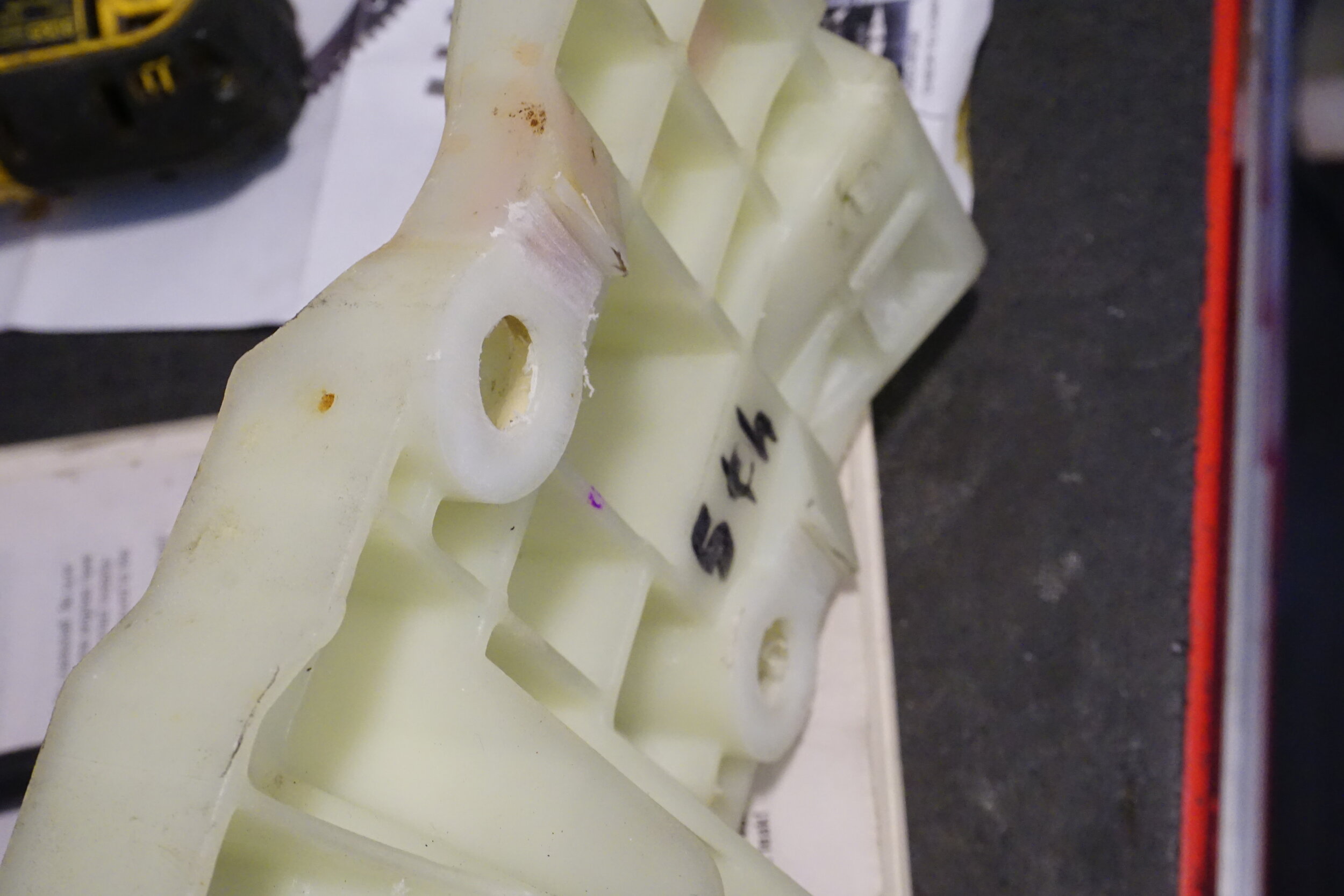
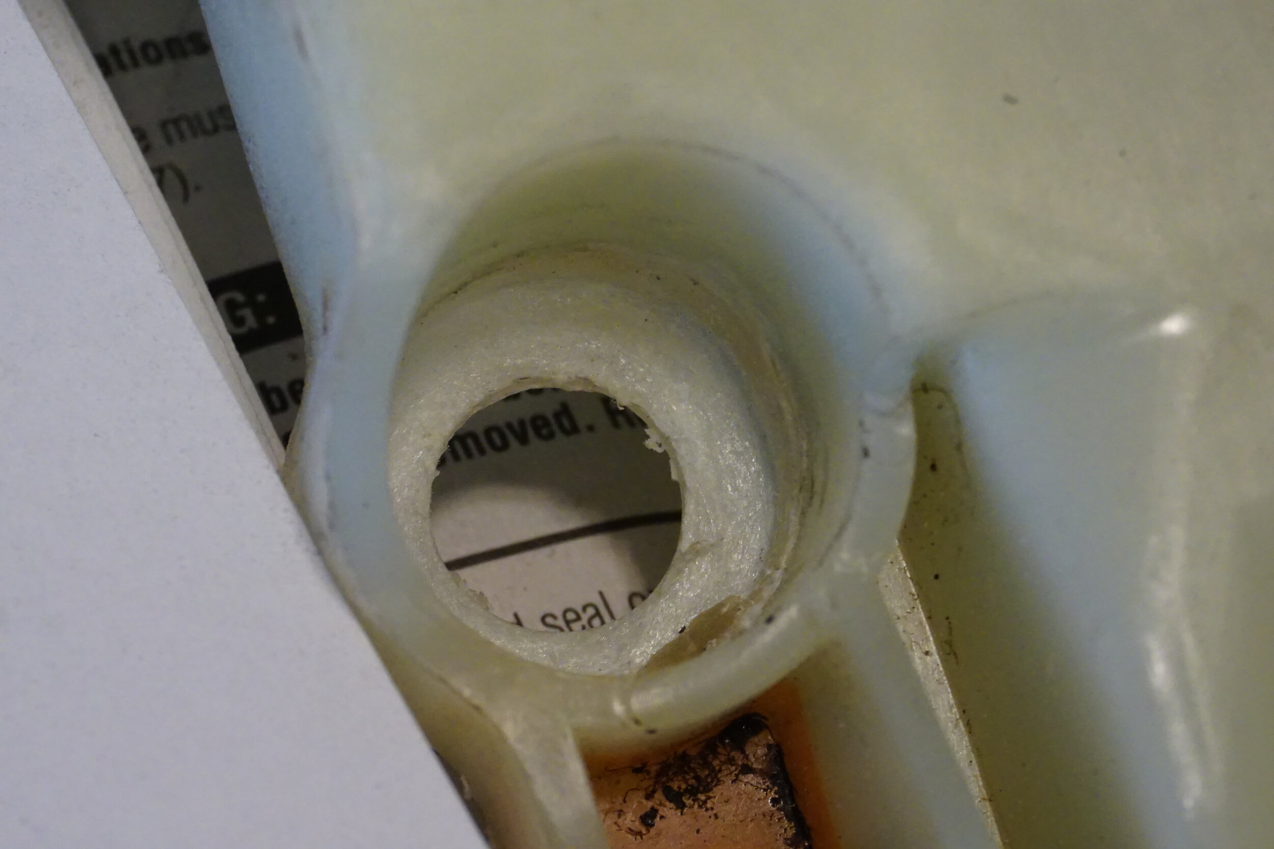
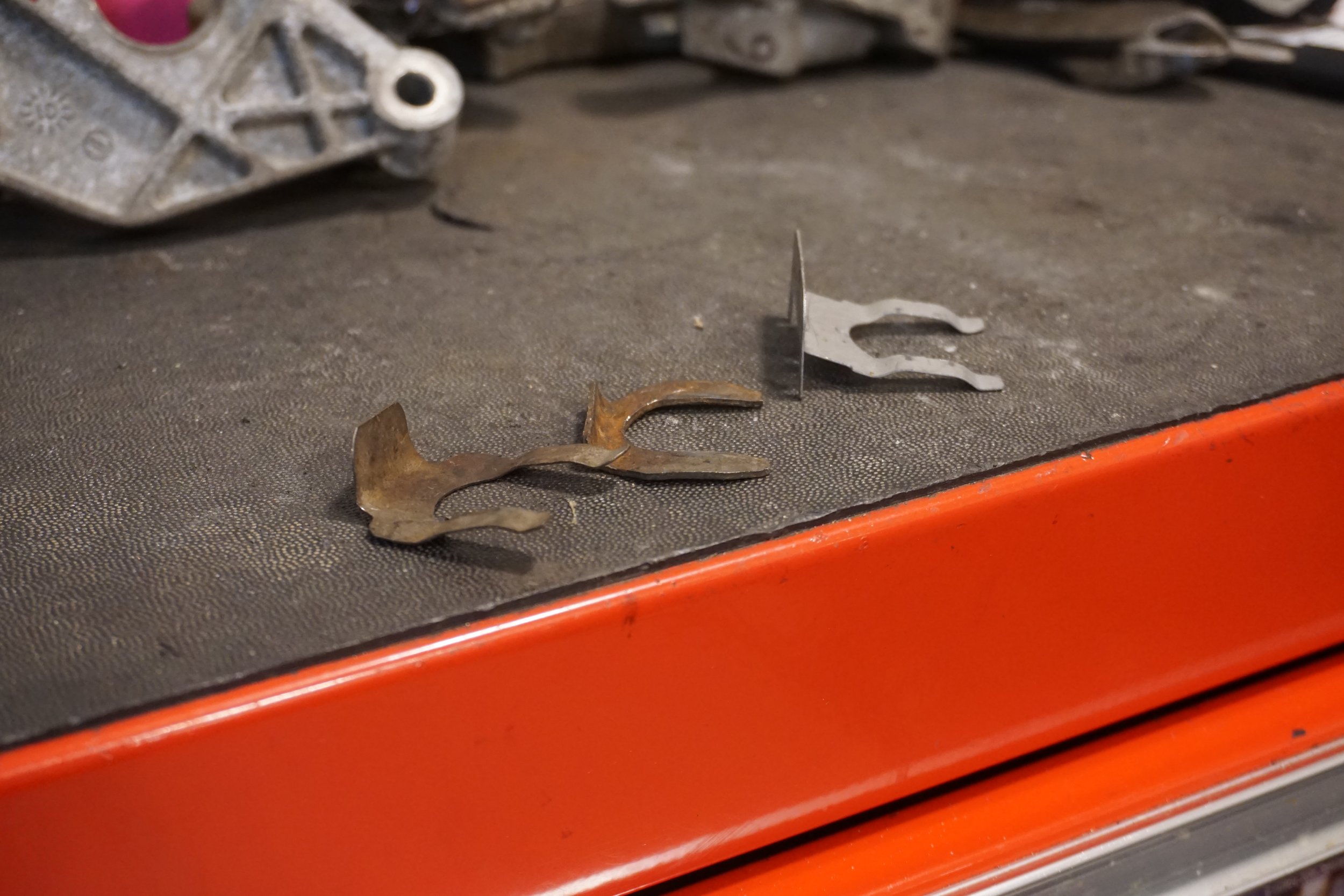
  • When changing the oil gallery gasket, this is a good time to grind away the center portion of the power steering bracket before reassembling the front of the motor.
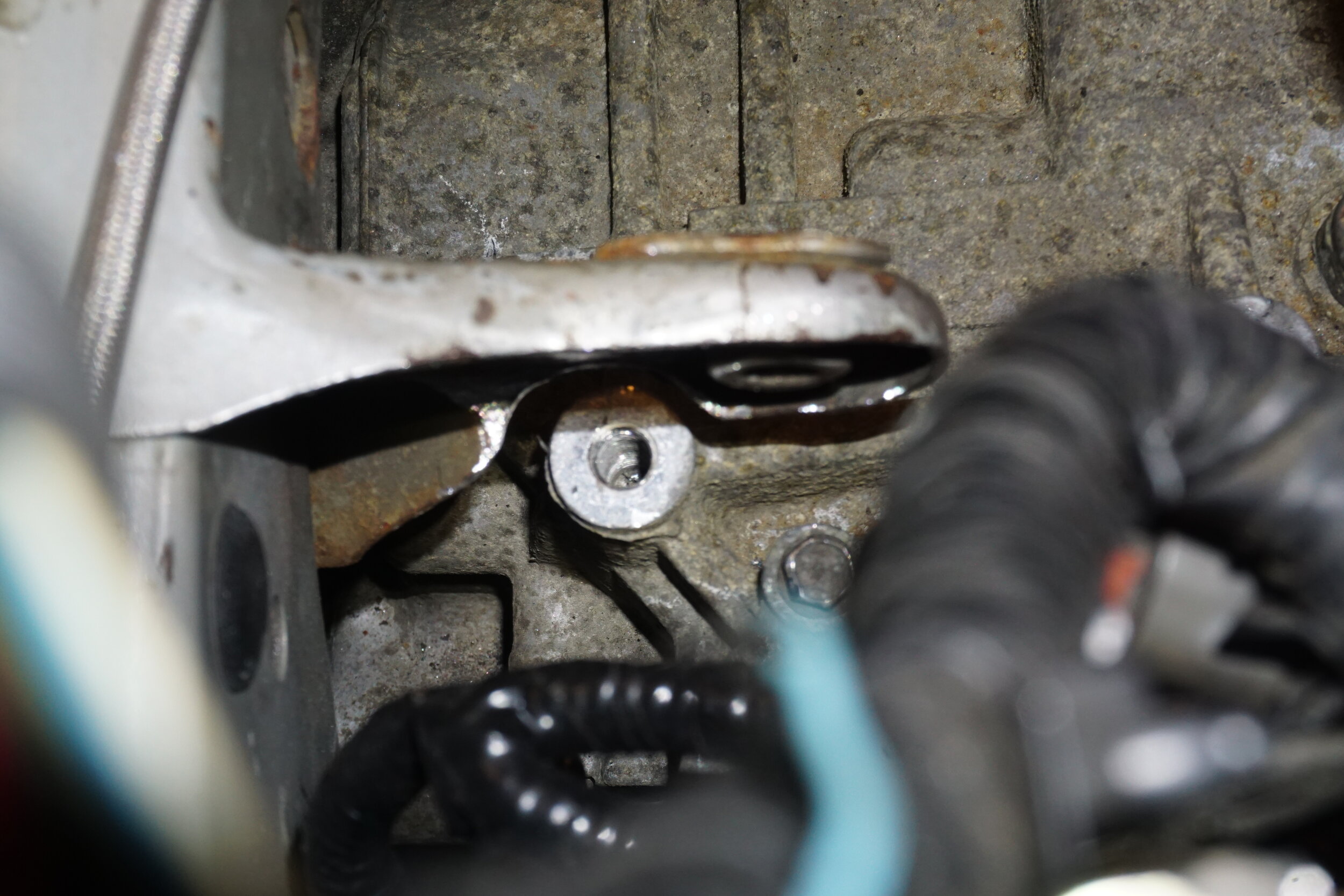
  • Grind/cut away the center portion of the power steering bracket. This requires some aggressive cutting, but also needs some attention to detail (cutting too DEEPLY can weaken the integrity of the timing cover. Cutting too WIDE can weaken the remaining brackets that will be needed to hold the alternator):
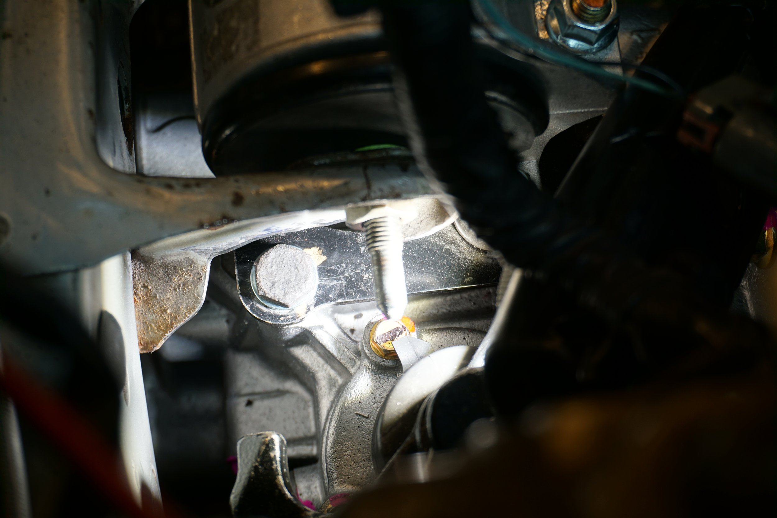
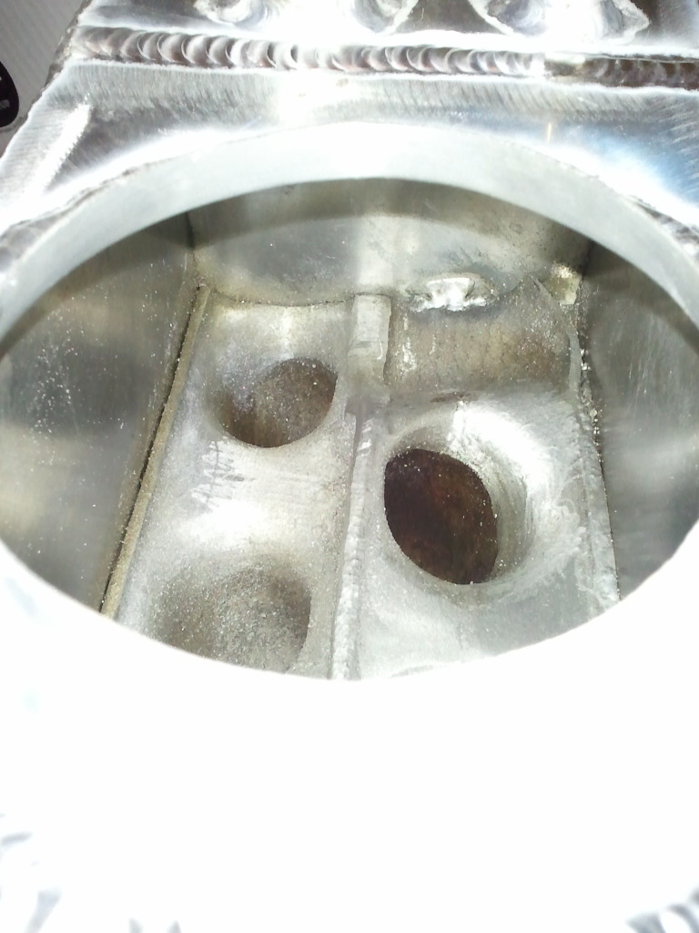
  • Grind/cut away a portion of the metal where the idler pulley/tensioner spacer was:
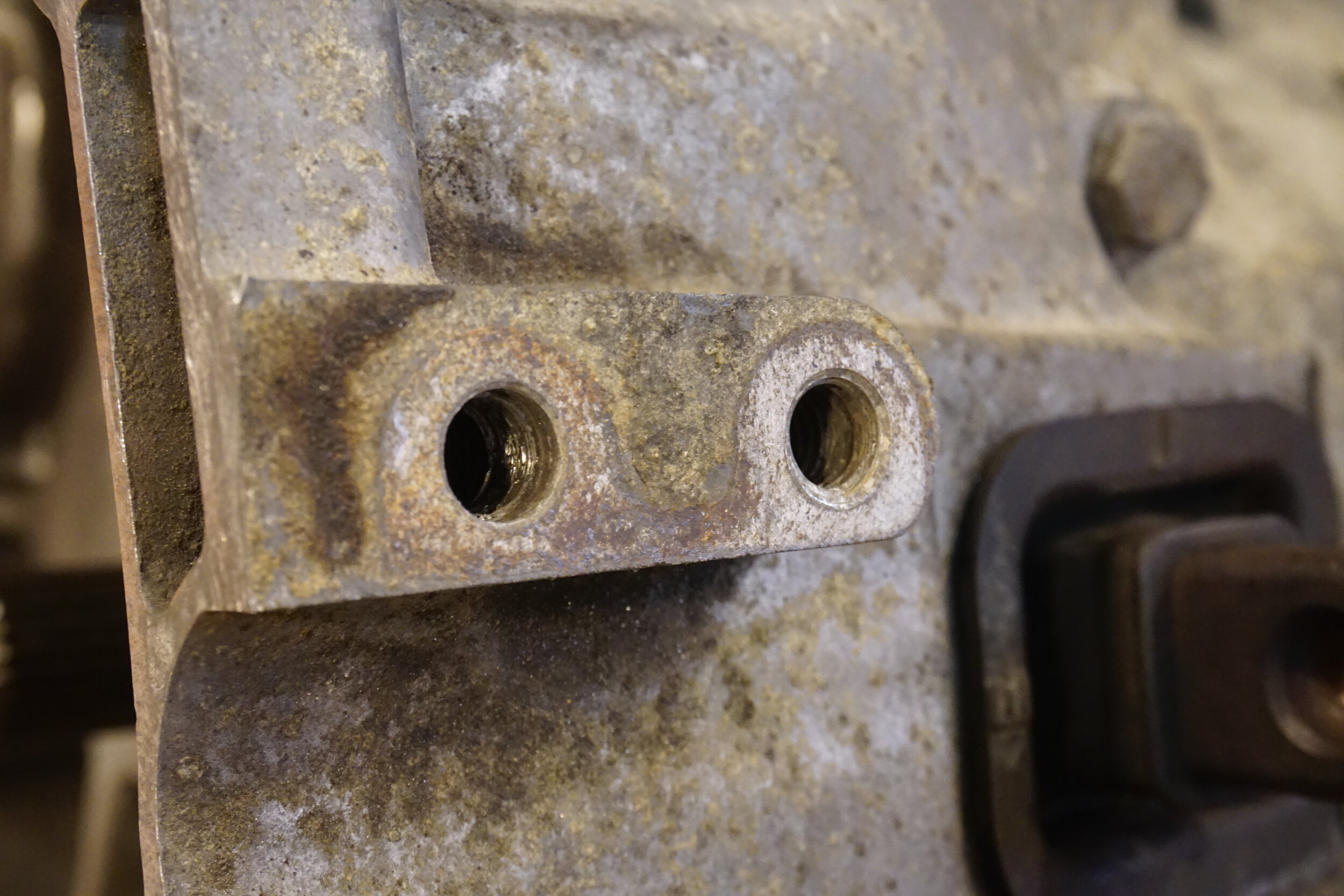
  • Remove exhaust manifold studs at the rear most exhaust port (close to the trans). This requires an ‘E8‘ torx socket:
  • Clean out the threads in the opposite holes using a ‘10×1.25‘ tap.
  • Replace the removed studs into the newly cleaned holes:
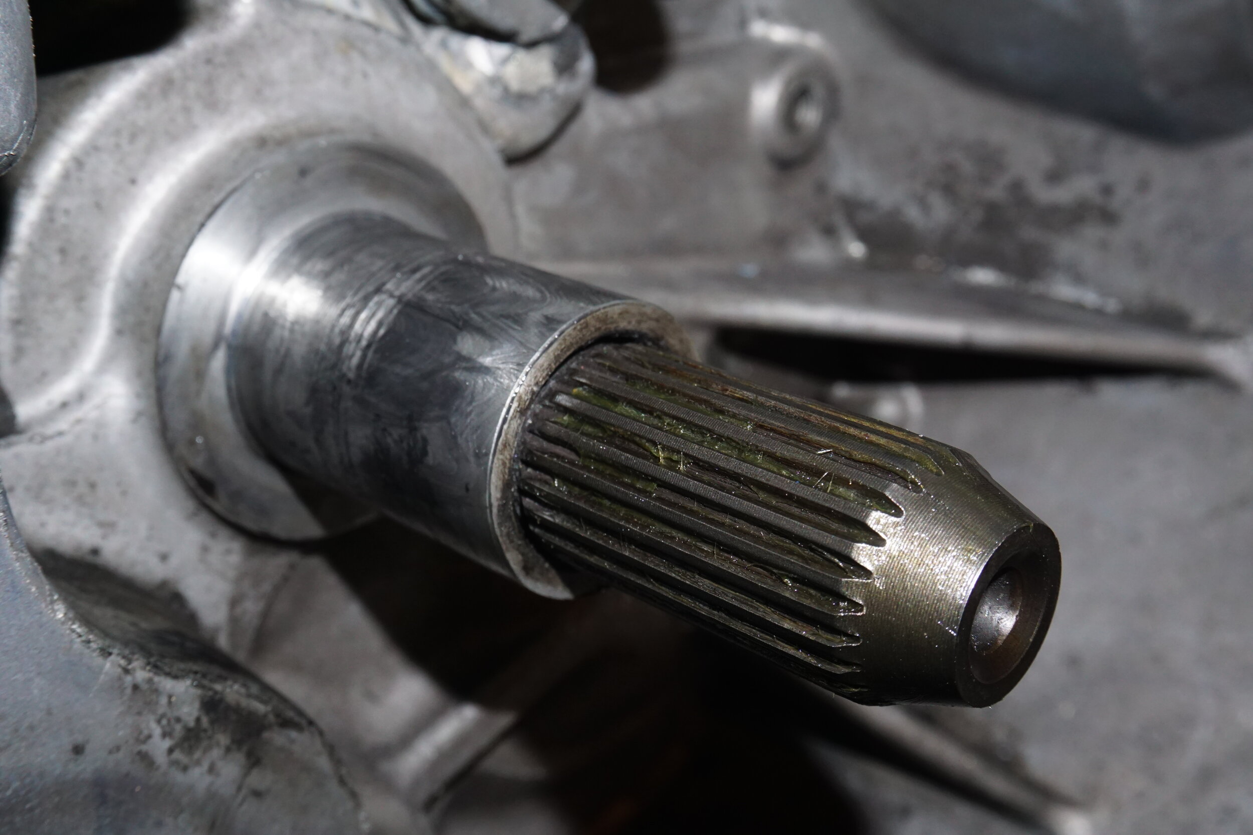
  • Remove lower oil pan.
  • Remove upper oil pan.
  • Use the oil pan from a 3.5 DE motor…but remove the windage tray. Add your o-rings and seals, and install upper oil pan onto the HR motor.
  • Remove the HR water pump access cover, and replace it with the one from the DE motor
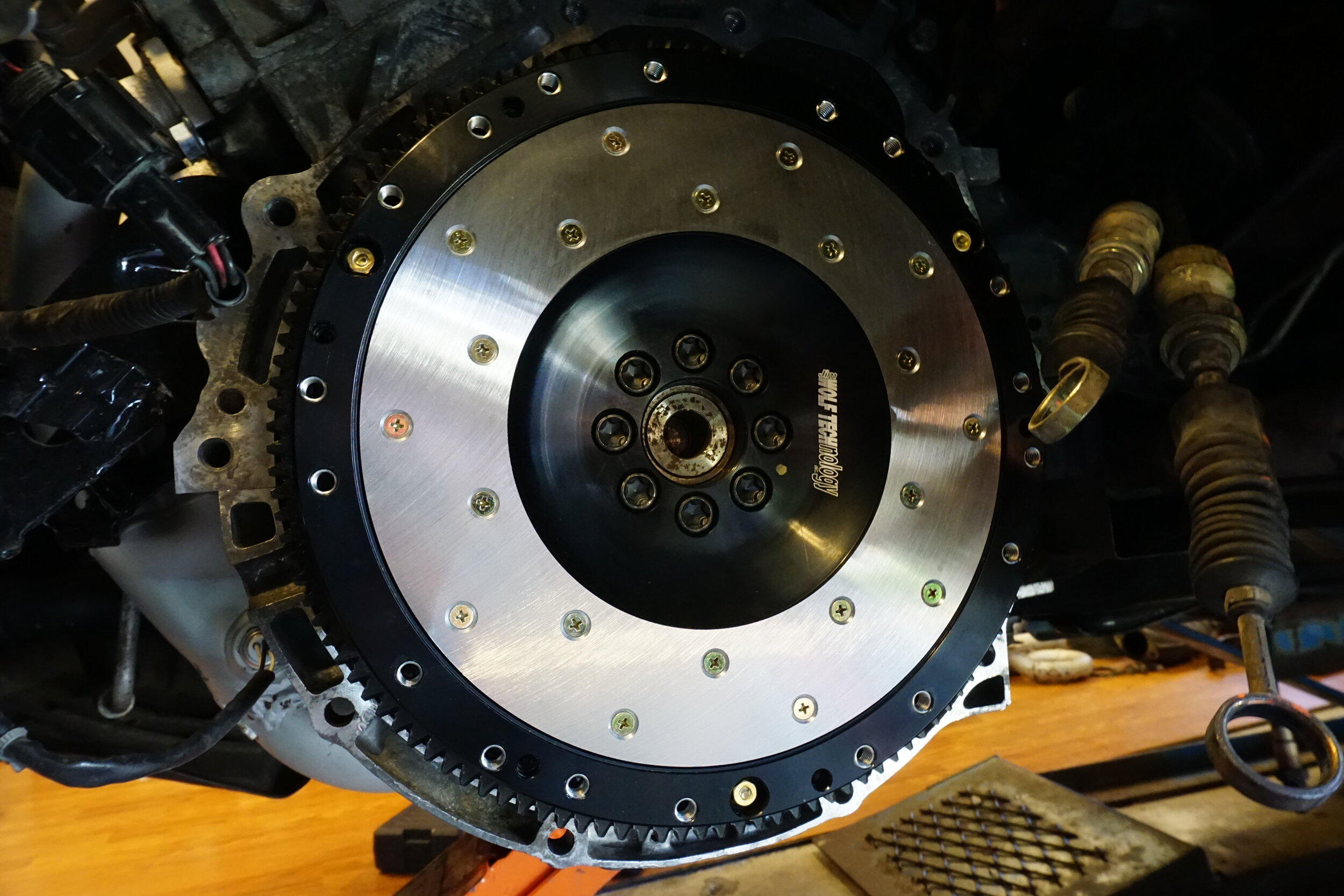
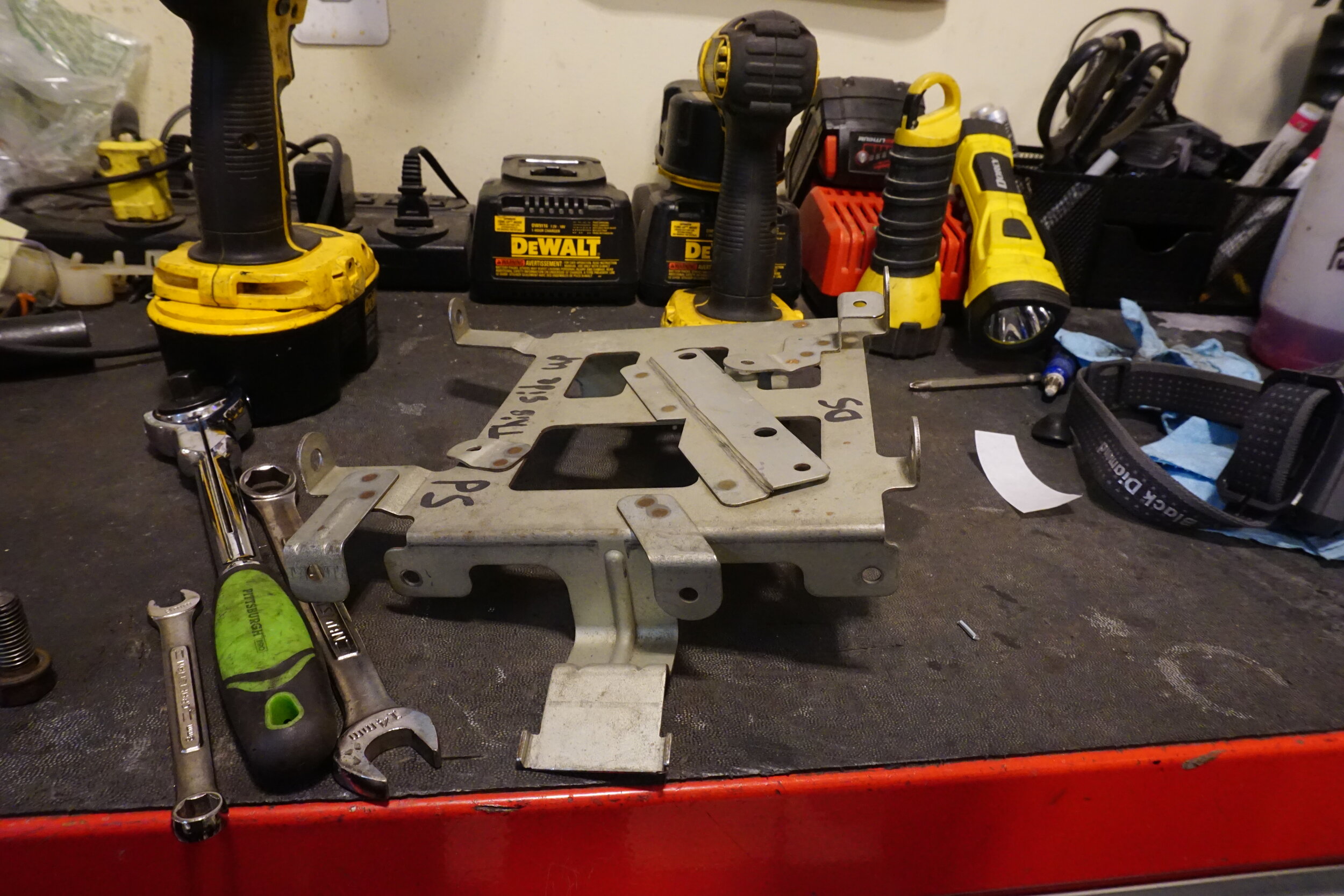
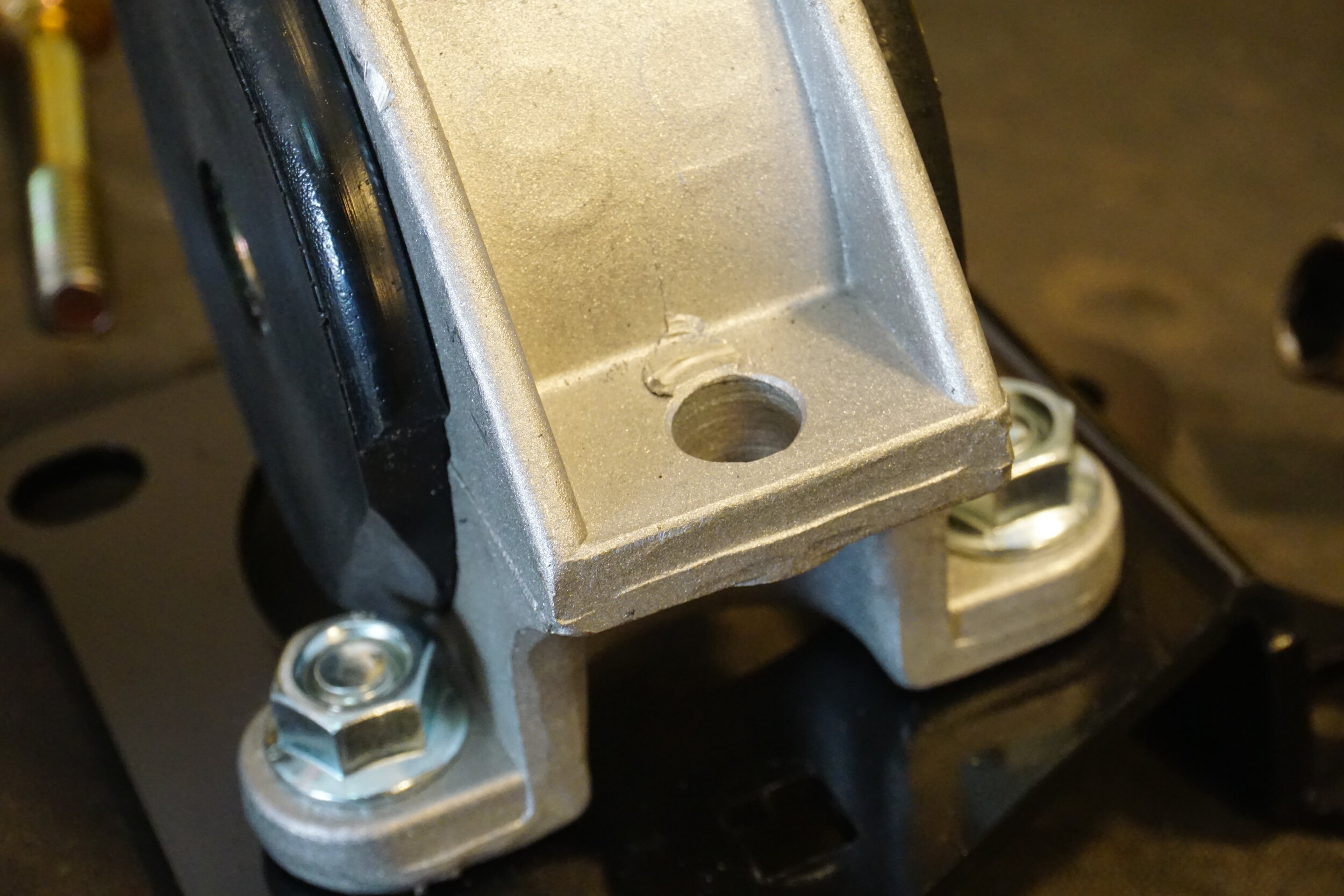
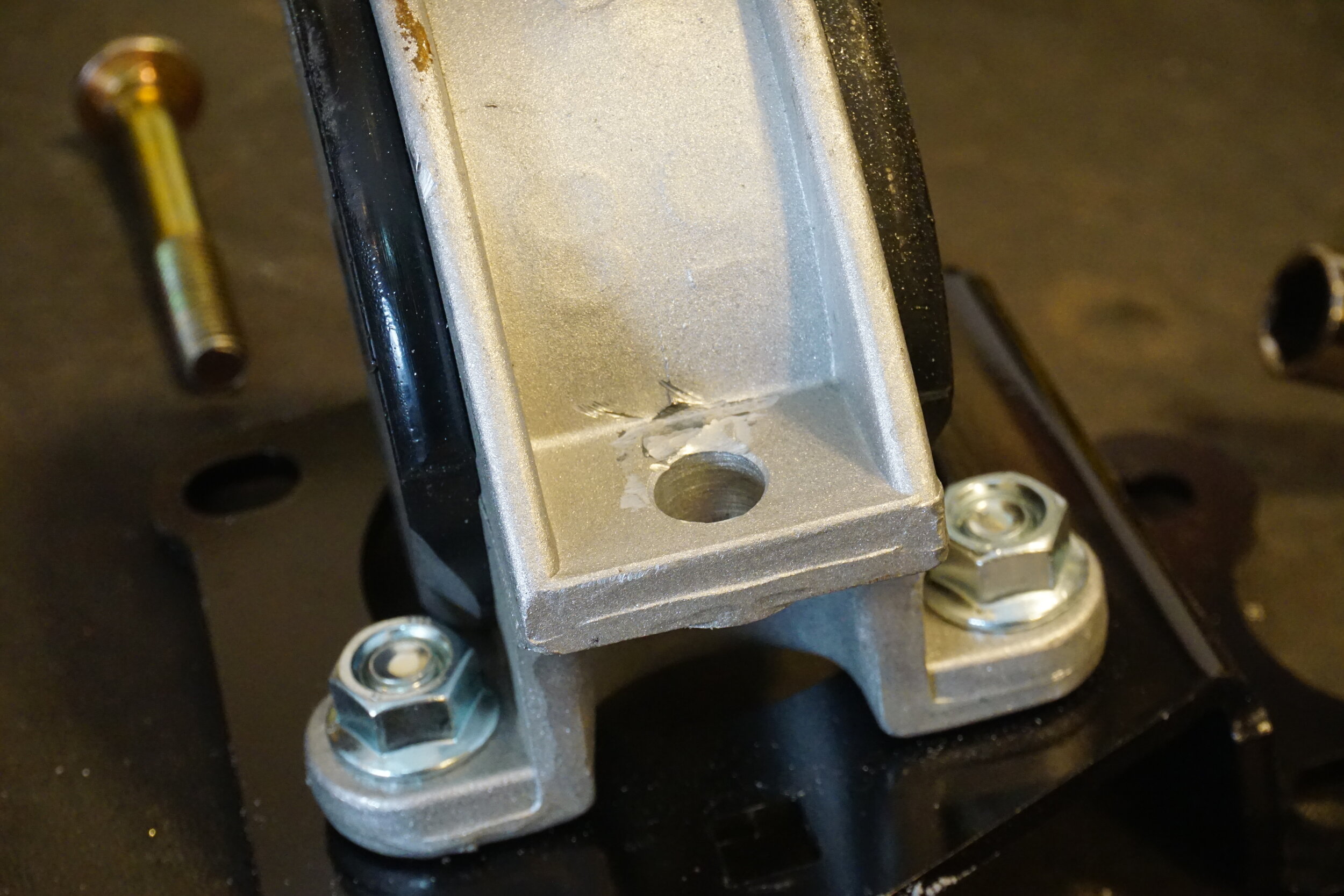
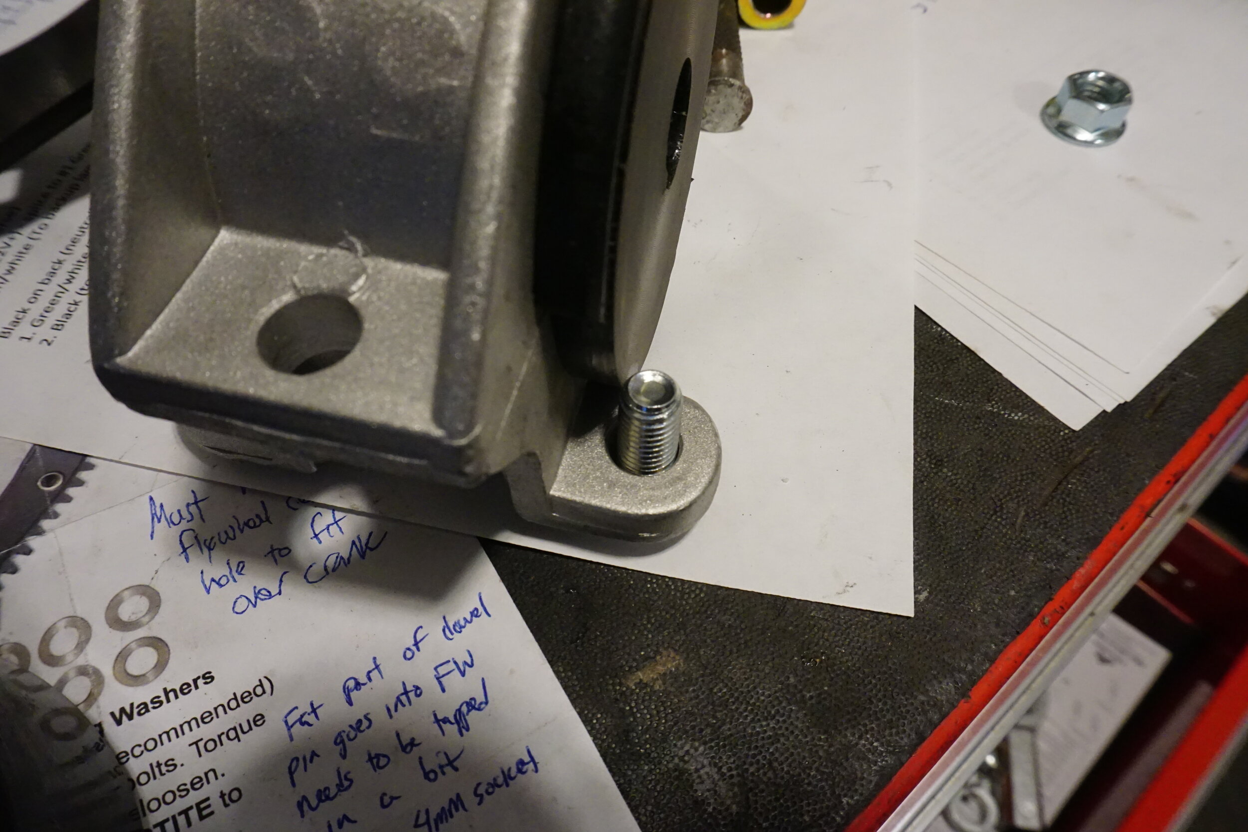
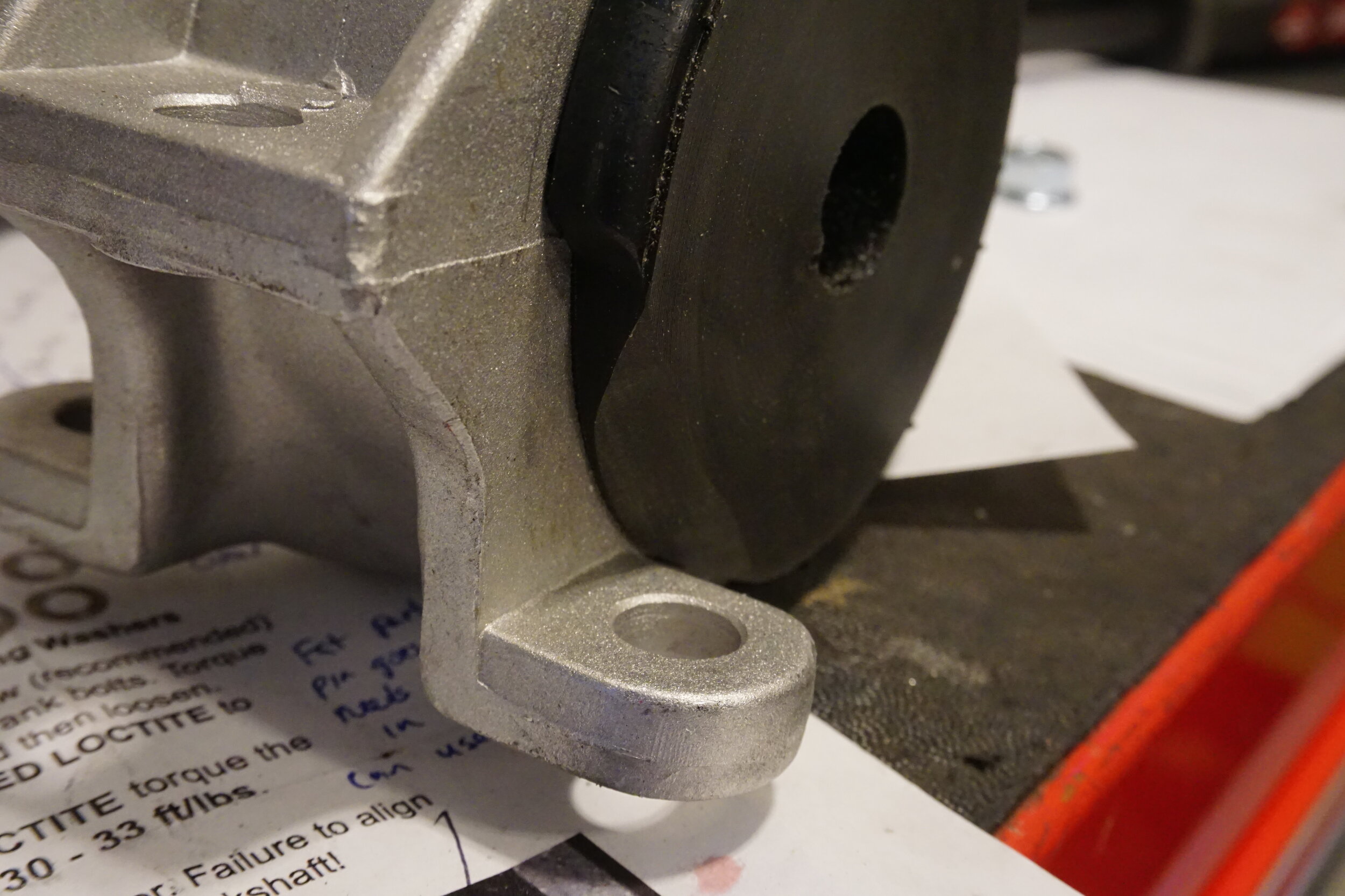
  • Alternator bracket
  • Belt tensioner bracket

Adjusting the Cam Signal Trigger Wheel

*Please note that we now offer a completely bolt on trigger wheel that eliminates the need to modify your stock trigger wheels*

If you choose to modify your stock trigger wheels, please note that this is a VERY important step and it must be done very carefully for your car to run properly. You have to be extremely accurate.

Apart from the wiring, adjusting the signal wheel is the most detailed work you need to do on the swap. It is important to be very accurate when cutting or grinding, and it’s also extremely important to assemble everything correctly at the end of this step. Pay close attention to the pictures and make sure that your work looks EXACTLY the same!

*You will need to modify your 5/16 Allen key by cutting the arm down so that it is approximately 3/8″ long. This is your ‘special tool’ that you will need to use in this part of the swap.

  • Open one of the valve covers.
  • Using the ‘special tool’, loosen the signal wheel lock nut and remove the signal wheel from the intake cam:
  • Completely remove the inner nubs from the signal wheel without damaging the rest of the inner surface:
  • Add Loctite to the flat inner surface of the signal wheel:
  • Reconnect the modified signal wheel to the intake cam…be sure to place it at the proper angle (as shown below) and resecure the lock nut:
  • Close and bolt down the valve cover
  • Open the other valve cover, and repeat these same steps.

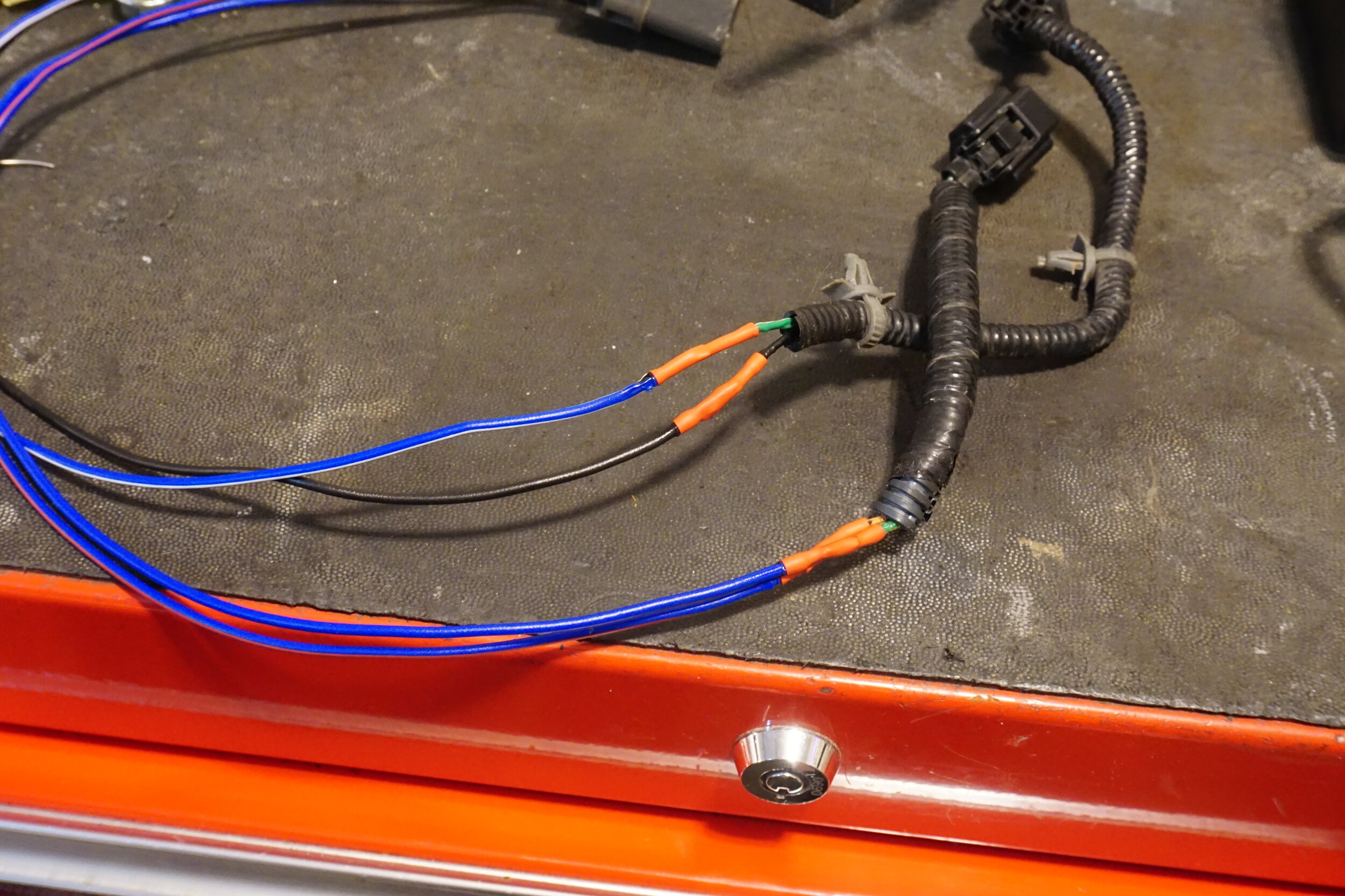
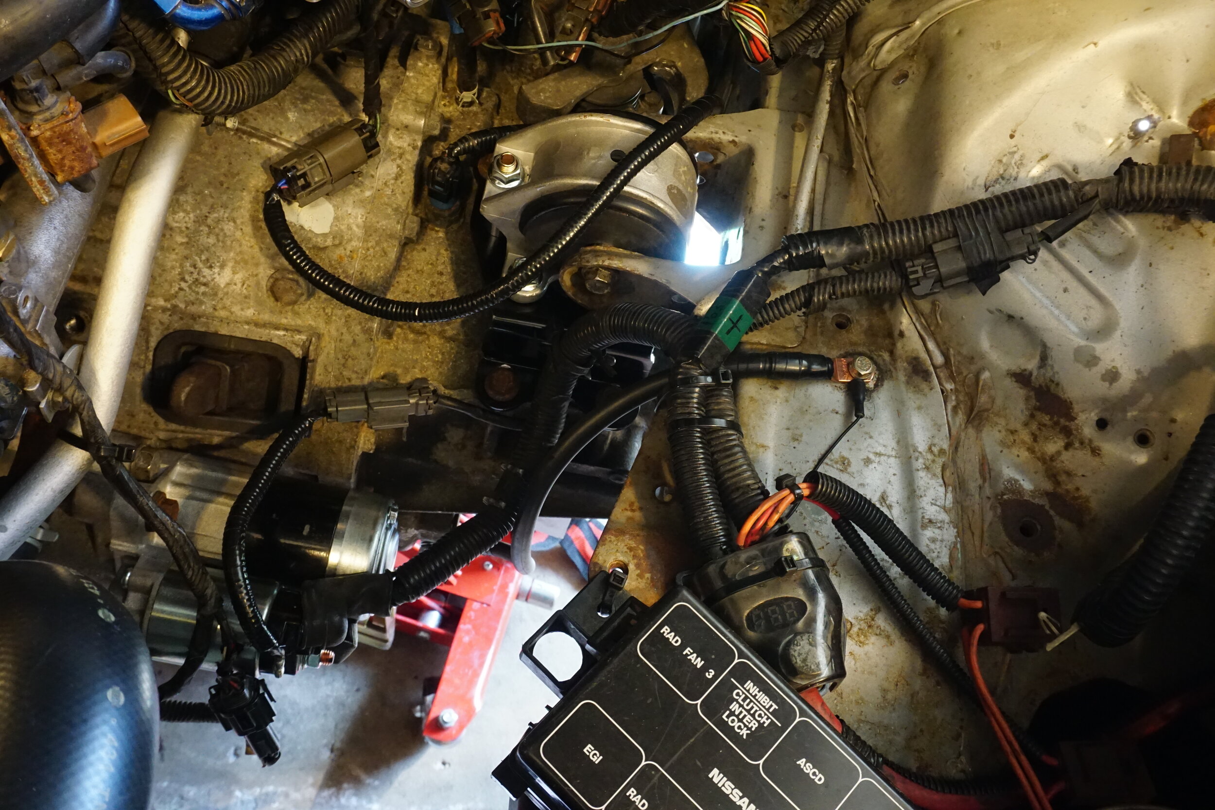
V2 Cam Sensor Signal Inverter Wiring

V2 inverters are single channel. One inverter is required for each camshaft position sensor.

Wiring for cam sensor signal inverter

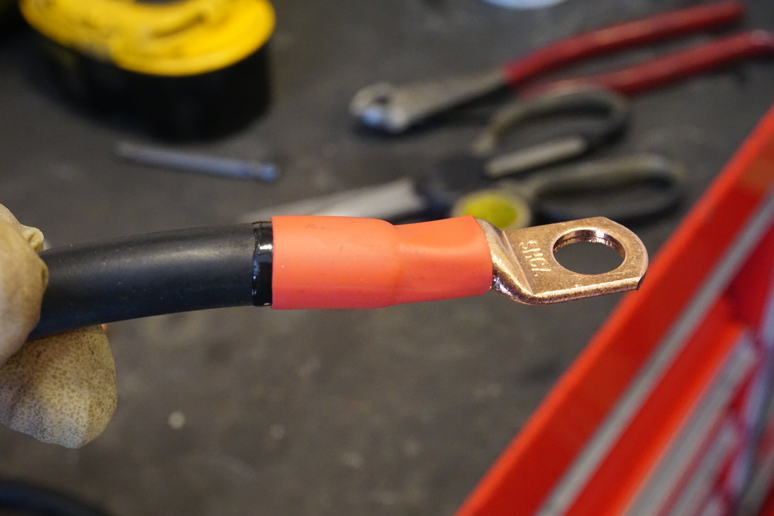
  • Red wire – 12 volt power supply ( power going into the board )
  • Black wire – Ground
  • Orange wire – Signal out ( connects to existing wire on ecu side )

Picture below demonstrates the older style DE cam sensor plug that is cut off when wiring in inverter with required wiring

V1 Cam Sensor Signal Inverter Wiring

The wiring harness in your car needs to be connected to the newer motor, and it’s not just a ‘plug-and-play’ situation. These diagrams show you the changes that need to be made to make your DE harness control your HR motor:

** THESE WIRE CONNECTIONS ARE CRITICAL. MAKE SURE THAT THEY ARE CONNECTED CORRECTLY (ACCORDING TO THE INSTRUCTIONS), AND SECURELY. TWISTING THEM TOGETHER IS NOT GOOD ENOUGH. **

The stock cam signal wire will be intercepted (cut) by the cam signal inverter supplied with the swap kit. There are six wires on the cam signal inverter…here’s how you connect them:

  • the RED wire goes to a 5v source from your car’s harness (to supply power to the sensor)
  • the BLACK wire is ground

For Cam #1…cut the existing wire:

  • the YELLOW inverter wire connects to the existing wire on the CAM side
  • the ORANGE inverter wire connects to the existing wire on the ECU side

For Cam #2…cut the existing wire:

  • the BLUE inverter wire connects to the existing wire on the CAM side
  • the GREEN inverter wire connects to the existing wire on the ECU side

Loading

Community Member Credit: 95maxrider

I recently installed a 6 speed into my 4th gen using one of the how-tos, and while it was improved over the original guide, it left out a lot of details, so I wanted to make my own guide with new pictures and details to help people do this swap in the future. New parts are also available now that weren’t available when older guides were written which make the swap easier and reversible.

Required Parts:

  • 6spd Maxima transmission-You can use the 6 speed from 5.5th or 6th gen Maximas. The external physical dimensions are the same, but internal differences include different final drive ratios (3.8 for 5.5th gen, 4.1 for 6th gen) and synchros (double for 5.5th gen, triple for most 6th gen).
  • 5.5 gen 6spd Maxima shifter assembly– I didn’t try, but I’m pretty sure the 6th gen shifter assembly can also be used.
  • 5.5 gen 6spd Maxima shifter cables– 6th gen cables are longer and will be more difficult to fit. Attempt at your own risk.
  • 5.5 gen 6spd drivers side axle– Not actually necessary, as the stock 5 speed (open diff only, not VLSD) axle can be used.
  • 5.5 gen 6spd passenger axle
  • 6spd frame transmission mount- Buy the front (drivers side) motor mount for an SR20 Sentra. 11210-0M800, about $30. Will also need Energy Suspension poly insert for that mount,
  • 6spd transmission mount bracket- Buy the custom adapter bracket made by Schmellyfart (schmellyfart@gmail.com), which allows you to use the factory frame mount so you don’t need to cut it off like in previous guides. This allows you to easily revert back to a 5 speed if desired.
  • Passenger side axle carrier bracket– You can reuse your 4th gen bracket, it’s the same as a 5.5th gen bracket.
  • Aftermarket Maxima 6spd flywheel – I used a JWT flywheel, but Fidanza can also be used. Around $450.
  • 6spd clutch– I put together OEM parts for my clutch/PP setup. Users report this setup can support 300 whp.
  • 2003-2005 350z clutch disk 30100-CD019 – $135
  • 2005 Maxima pressure plate 30210-7Y010 – $210
  • 9 bolts (PP to FW) 30223-07S00 – $11
  • 9 washers 30240-07S00 – $22 (JWT flywheel includes washers, so these may not be necessary)
  • 8 Flywheel bolts 12315-8J100 – $22
  • Pilot bearing 32202-B950A – $4
  • Throw out bearing 30502-41U20 – $47
  • Custom 5 spd timing ring (same number of teeth and spaces as 5 speed, but no offset)- Schmellyfart (schmellyfart@gmail.com) makes these as well, support him so he can make ever more cool parts for our cars!
  • 6spd starter– I paid about $100 for a new one on RockAuto
  • 6spd slave cylinder– I paid about $20 for a new one on RockAuto
  • 5spd or 6spd bell housing bolts

Fluids:

  • Brake fluid
  • GL-4 transmission fluid (Motul, Red Line or Amsoil preferred)
  • Brake parts cleaner
  • Red Loctite
  • White lithium grease / Lubro-Moly Long Life Grease + MoS2 / Sachs High Performance Clutch Spline Grease for
  • The throw out bearing and associated parts (follow the directions in the FSM!)

Optional Parts:

  • Rear main seal
  • Shift assembly lower cover from 2002/2003 Maxima with the 6 speed. This goes under the car and protects and insulates the shifter assembly. Highly recommended if you can find one, but they have a tendency to rust out. NLA from Nissan, must be found used.
  • I bought 2J Racing delrin shifter bushings. Red Lion Racing (on Facebook) and Energy Suspension shifter cable bushings can also be purchased.
  • Axle seals
  • Short throw shifter – I bought one from Axxtion, but 2J Racing also makes one. Users report the 2JR kit will leave the shifter slightly tilted to the front, while the Axxtion kit leaves it centered in the correct position. Unfortunately the Axxtion kit doesn’t fit A32s with ABS without repositioning the ABS pump.
  • Stainless steel clutch slave cylinder line
  • Speedometer pinion/sensor (if necessary) (32702-AD012). This plugs right into the 4th harness, no wiring modifications are necessary.

Various sized metric nuts and bolts

Equipment:

  • Drill and step bits
  • Tap and die set
  • Impact gun
  • Flare nut wrenches
  • Bolt cutters/electric saw/angle grinder/metal cutting tool
  • Dremel with reinforced cut off wheels and metal grinding bits
  • Propane/MAP torch
  • OTC 4754 Universal Pulley Holder Wrench (optional but helpful)
  • Wire crimping supplies and/or solder iron and supplies
  • Electrical tape and/or split wire loom tubing, heat shrink tubing
  • Engine Traverse Bar (to support engine from above when you remove crossmember)

Helpful notes:

Identifying transmissions in junkyards:

You can also visually inspect the transmission and tell if it’s HLSD. If you look through the axle holes on either tranny you can see out the other side. On the HLSD you can see through with nothing in the way. You’ll see a perfect circle. On the open diff tranny there is a round bar in the way partially blocking the view through. You’ll see a half circle.

How to tell if HLSD?
-Metal pedals with rubber grips
-Plate on firewall by driver, RS6F51H, H as last digit means HLSD, A is open diff

6th gen axle info:

6th gen passenger side axles are slightly longer than 5.5th gen axles, and 5.5th gen axles are quite a bit longer than 4th gen axles. When installed, 5.5th gen axles are already compressed and close to binding, so 6th gen axles are not recommended for 4th gens. Also, the carrier bracket for 6th gens is very different from 4th/5.5th gens, and can only be used with 6th gen axles.

Wiring up the 6 speed starter:

The 6 speed starter ground cable is a female connector, and so is the connector on the engine harness. I cut the male connector off of a 5 speed starter and soldered it onto the 6spd starter. Don’t forget to slide some heat shrink tubing on the wire before soldering together. I forgot to do this! For extra protection you can wrap the area with electrical tape. And for an OEM look, protect all the wires with split wire loom tubing.

Wiring up the park/neutral position sensors for the 6 speed:

On 5 speeds the PNP switch/sensor is a single piece on the bottom of the trans. On 6 speeds, it was switched to being two switches/sensors, so you will need to need to splice wires together so your car gets the right signals and doesn’t throw a CEL. You want your reverse lights to work, don’t you? On the 6 speed, the blue sensor on top is for reverse lights, and the black one on side back is for neutral. Cut off the wires from the PNP switch on your 5 speed so you’re left with about 12″ of wires and the connector that plugs into your body harness. Leave the switch in the 5 speed. Here’s how you’re going to wire that up to the connectors for the 6 speed.

Reverse (blue connector on top of the trans)
Connect the orange (12V+) wire on the 6 speed harness to the blue/red wire on the 5 speed PNP harness.
Connect the green/white (to backup lamps) wire on the 6 speed harness to the solid blue wire on the 5 speed PNP harness.

Neutral (black connector on the back of the trans)
Connect the green/white (to ECM) wire on the 6 speed harness to the blue/white wire on the 5 speed PNP harness.
Connect the black (to ground) wire on the 6 speed harness to the black wire on the 5 speed PNP harness.

Make sure you slide some heat shrink onto the wires before you crimp or solder them together to protect the connection from moisture. For extra protection you can wrap the area with electrical tape. And for an OEM look, protect all the wires with split wire loom tubing.

1995/96 cars with giant EVAP canister on firewall under master cylinder:
You will need to cut/grind the shifter cable bracket so it doesn’t break your EVAP canister when you try to get the trans mounted in place.

Interference:

Original:

After cutting and grinding:

If your car has ABS:
Previous guides correctly noted that the bracket for the ABS pump (under and in front of master cylinder) gets in the way of the shifter cables/levers and said to remove the bracket for the ABS pump. I believe this is unsafe and strongly recommend you do not do this. Their solution was to hang the heavy ABS pump with a zip tie from the master cylinder. This is a bad idea and would not pass tech inspection at any sort of racing organization. The proper solution to this problem is to use either an angle grinder with a cutoff wheel or a Dremel with reinforced cutoff wheels to remove portions of the bracket that interfere with the shifter parts, and leave the rest of the bracket to support the pump. This is much easier with the bracket removed from the vehicle, so remove and cut yours while you don’t have a transmission in the car. I recommend painting the bracket when you’re done cutting to prevent the bare metal from rusting.

Original bracket:

Cut and painted:

Install guide:

JWT Flywheel: To install the custom timing ring from Schmellyfart onto your JWT or Fidanza flywheel, you will need some sort of torch to apply heat to the screws that hold on the ring that JWT supplies. JWT uses Red Loctite to the small screws, so if they are not heated up you run a very good chance of stripping them, which is really going to suck. Heat them up one at a time, then loosen by hand, do not use an impact. One they are all removed, remove the JWT timing ring and install the one from Schmellyfart. Apply Red Loctite to all the little screws and reinstall them. Since they are so small there is no torque spec, just make them hand tight and do not tighten with an impact.

The JWT flywheel arrived with a thick waxy/oily coating to prevent the surface from rusting. This will need to be fully removed before installing so you don’t contaminate your clutch disc material. I first used some 3M Adhesive Remover on rags, making sure to also remove the wax from the top of the screw heads. Once it looked clean, I blasted the whole thing with brake cleaner to remove any residue. Make sure you also spray your new pressure place with brake cleaner for the same reason.

To install the JWT flywheel follow the included directions. Mine barely fit over the crankshaft and had to be hammered on with a rubber mallet. I recommend leaving the flywheel in the sun for a few hours before installing so the metal heats up and expands. You will need something to keep the crankshaft from rotating while you torque the bolts that attach the flywheel to the crank. I used the OTC Pulley Holder tool mentioned above, although some people will just put a socket over the crank bolt and hold it with a breaker bar. I chose to have a helper hold the pulley holder tool for me while I worked the flywheel bolts. It’s very important that you torque the flywheel bolts to the proper spec and that the flywheel is perfectly flush with the crank. JWT also recommends using Red Loctite on the flywheel bolts, and while that may make them damn near impossible to remove in the future, I chose to follow their instructions. I just didn’t apply very much. If you need to remove them later, be sure to use plenty of heat.

Don’t forget to very thoroughly clean up the mating surface between the engine and transmission, otherwise your starter might not have a good ground path and the car won’t start. Clean both the engine and the transmission! I used one of these plastic bristle things so I wouldn’t damage the aluminum.

Now is a good time to chase the threads for the two bolts that hold the slave cylinder in place, mine were pretty grungy.

I recommend also cleaning up the area around the ground cable on the transmission so it can make a good connection.

Make a new ground cable using the appropriate glue-lined heat shrink.

Here’s how mine looked when I was done:

Getting the transmission in place:
I removed my crossmember when I removed the 5 speed. You will need to support the engine from the top before you remove the crossmember so the engine doesn’t fall on you. Theoretically you could support the engine oil pan with a jack stand, but that’s really not a good idea as your only means of support. Best bet is to use an Engine Traverse Bar.

I tried to use my transmission jack to get the 6 speed in place, but no matter how I oriented things, it just wouldn’t fit. Don’t waste time like me, just bench press the trans until the input shaft lines up with the hole in the crankshaft, it takes like two minutes. Be mindful of the dowel pin on the rear, it needs to line up before you start tightening bolts.

I removed the shifter cable bracket from the trans before installing it, which made getting it into place much easier.

Cutting the firewall, running the shifter cables, and installing the shifter:
If you are doing this with the engine still installed, be prepared for a tight squeeze. I could not get a straight shot on the firewall to use a step bit on my drill gun to make a nice round hole, so I had to improvise. I have a flexible arm attachment for my Dremel that allows it to reach into tight areas very easily, and that’s what I used to cut my ugly, square-ish hole with reinforced cutoff wheels. I’m embarrassed by the results, but it’s what I could do with the space available. You will need to seal the hole in some way, either with sound deadening material, silver HVAC tape, or something else. When I pull my engine I plan on drilling two holes and hard mounting it to the firewall.

I had a hard time getting the cables into the cabin of the car. I chose to remove the ECU and the metal ECU cage from the car as I just didn’t see a way to get the cables to the shifter with them in place. This part is much easier if you have a helper guiding the cables in the car while you push from the engine bay. Get the cables roughly in place and reinstall the ECU cage and ECU. I had to fold some metal flat on top of the cage to allow the cables to go where they wanted to go since space is so limited in this area.

As for the shifter assembly, there are bushings on each of the 4 bolt holes. The two front bushings must be removed because if not, the bolts attached to the floor won’t be tall enough for nuts to thread onto. You will need 2 nuts and bolts for the back holes. I noticed that even with the front bushings removed there were very few threads for the nuts to grab onto, so I decided to grind away some of the plastic from the top and bottom of the shifter assembly around the bolts to thin the plastic out and allow the nuts to grab more threads on the studs from the body. I used an oval grinding stone on my Dremel to grind away material from the top down, and then a flap wheel on my angle grinder on the bottom. I’m guessing I removed about half of the material thickness, and this allowed me to securely install nuts. Before installing the nuts, I installed a washer or two in the hole so that the washers were level with the plastic, which I hope will prevent any movement in the shifter assembly and will also provide the best base for the nuts to clamp down on.

Regarding the shifter cables and bushings on the transmission, I used a set of 2J Racing delrin bushings instead of the stock rubber bushings. I added a couple washers above and below the bushings to bring the stack up closer to the retaining pin/clip. But the assembly needs to rotate freely, so do not stack washers too tightly against the pin/clip.

Another thing I learned was that the retaining clips that holds the shifter cables to the bracket really should be the thicker variety, rather than the thinner and flimsier version. I no longer remember which cars had which version (whether 5.5th or 6th gen), so if you only have the thinner ones, you may want to order the beefier versions from the dealer or go scrounge around in junkyards. If you can only get the thinner ones, the more important thing to note is their orientation when you install them. I initially installed one of them from the top down, but this allowed the bottom of the shifter cable to not seat fully and wasn’t flush with the bracket. Installing the clip from the side resolved the issue and the cable was properly secured against the bracket.

Thick version is in the middle:

Schmelly’s transmission bracket

I’m writing this section something like two years after I did the install, so I’m going to gloss over a lot and possibly forget things. The bracket I got from Schmelly was a prototype, so fitment wasn’t perfect. Things may be different now, so please check with him. I basically had to grind some metal from a couple areas, nothing too serious.

First up was a small area of the body mount, on the rear part of the mount. Do this while the transmission is still out of the car!

I eventually took even more metal out to make tightening up the bolt below easier.

Then I had to grind a bit from the SR20 mount so the nut could sit flush, as I encountered some interference from rough casting marks.

One of the bolts was too close to the Energy Suspension insert for the SR20 mount, so I shaved off some poly.

And to get the bolt/holes to line up for the mount, I had to use a pry bar between the frame and the trans to force things into alignment.

All done!

Loading

Community Member Credit: CS_AR

Over the past couple of months, I have received several requests to post information on the sub-frame spacer modification. It has taken a couple of months to try several different products and approaches to finally settle on a method that I feel comfortable sharing.

All total I must have spent $400 on an assortment of poly bushings, washers, ceramic magnets, and spacers to finally reach an approach where the modification can be repeated in the $90 to $100 per vehicle range. Since I paid $90 for the original set of spacers that I’m replacing with a hopefully better product, I think it will be worth it. I want this modification to last for several years.

This modification uses a combination of parts from the following vehicles:

1) Nissan 300ZX Aluminum Sub-frame Spacers
2) Nissan Titan Truck PRG Delrin Suspension Spacers
3) Subaru WRX – Perrin 4268 Sub-frame Bushings

Installation Vehicles

1998 Maxima GLE – Recently converted to SE suspension. Note initially this modification was made to the stock GLE sub-frame. Later the 98 GLE was converted to use the triangular sub-frame braces from a 97 SE. Pictures of how the bushings look in both the stock GLE and upgraded SE type suspension are provided.

The suspension uses H&R Lowering springs with Koni STR-T orange struts. New Lower Control Arms (LCA) with end links, poly bushings, inner/outer tie rod ends have been installed. The mod was installed on a vehicle with basically a new front suspension. This car already had a very tight suspension before the modification was made. It just tightened it up a bit more.

1999 Maxima SE – This is the 2nd installation where I used this modification.
This vehicle’s suspension was replaced approximately 3 years ago with H&R lowering springs, KYB AGX struts, new Lower Control Arms (LCA) with end links, poly bushings, inner/outer tie rod ends have been installed. This is the 2nd time that subframe spacers have been used on this vehicle. The original mod was installed on a vehicle with basically a new front suspension. The 2nd (enhanced) modification was made after the 1st modification’s parts worked loose and fell out after approximately 2 years of use. Note this car also had a very tight suspension before the modification. This modification just tightened it up a bit more.

Post Installation Pictures

Front 300ZX Aluminum Subframe Spacer with PRG Delrin Titan/Armada spacer and flat washer.

Name: 04_New_Front_zpsvznoezqy.jpg Views: 772 Size: 190.8 KB

Rear 300ZX Aluminum Subframe Spacer with Perrin 4268 Subaru WRX Bushing

SE Type Suspension

Name: 06_Perrin_4268_Rear_zps7frbrbn1.jpg Views: 709 Size: 257.6 KB

Non-SE Type Suspension

Name: 04_Rear_Subframe_zpsmhzryxbv.jpg Views: 787 Size: 102.6 KB

The Problem

Space between the sub-frame mount post and the body results in a loose sloppy feel when driving over rough places in the road and lowers the amount of feedback from the rack to the driver.

Also, when the sub-frame upper post rubs against the body it can make a creaking noise.

Name: 71_Subframe_Rub_zpspnjgz2sp.jpg Views: 708 Size: 231.3 KB

Roughly 3 years ago, I purchased a set of plastic spacers to tighten subframe movement. Unfortunately, the upper spacers were not thick enough to completely stop the movement. Since the upper spacers are C-shaped, the upper rears spacers eventually worked loose and fell out on the street somewhere.

Name: 01_Old_Rear_Bushing_zps8lufxjx6.jpg Views: 731 Size: 230.4 KB

The old spacers helped after the initial installation. Since I could see the gap that remained between sub-frame post and the body would eventually allow the upper C-shaped collar to fall out. So I had to use Gorilla Tape as a temporary measure to wrap the area until I could come up with a tighter solution.

Looking back, I could have stacked up additional washers on the bottom post to remove slack. By then, I had already lost one of the rear spacers. Unfortunately, I just did not have a solution at the time when I realized the old spacers were too loose. Since the spacers are no longer available and the seller was not responding to email when I attempted to buy another set, I decided to find a repeatable solution using a combination common parts from other platforms.

Old to New Parts Comparison

The old parts are in the upper row.

Name: 20_Old_VS_New_zpsno9gk5cj.jpg Views: 688 Size: 351.0 KB

Comparing the Perrin rear lower bushing to the original lower spacer.

Here’s a picture of the new Perrin 4268 bushing that is used on a Subaru WRX compared to the old rear lower spacer. The Perrin bushing is definitely thicker and is capable of absorbing shock that may be transmitted to the rear part of the sub-frame.

Name: 21_Old_vs_New_zpsmlkyely1.jpg Views: 672 Size: 4.06 MB

Cost Summary

  • Aluminum 300ZX subframe spacers $25 to $28 depending on color. Shipping free from eBay sellers.
  • PRG Delrin Titan spacers (set of two) $20 + shipping
  • Perrin 4268 WRX bushings ~$10 + shipping.
  • Fastenal 33098 Washers $1 to $2 x 2 = $4 high
  • Harbor Freight Step Drill Bit $16 (with a 20% off coupon) to $20
  • Rough Estimate Total $90 to $100 depending on shipping costs.

Parts Sources

Perrin WRX Bushings Part Number 4268
Send an email to Thomas at the following email address: Sales@perrinperformance.com
Approximate cost is $5 each + Shipping.

There is a full set for the WRX that contains bushings that are not needed on the perrinperformance.com site. I was able to get Perrin agree to sell only part 4268 to Maxima owners.

300ZX Aluminum Subframe Spacers

Multiple eBay sellers – Prices vary based by color. Just search for 300ZX aluminum sub-frame spacers and go for the best deal.

Red – http://www.ebay.com/itm/Aluminum-Sub…RYbvZO&vxp=mtr

Silver (I bought silver because I didn’t want a color to get scratched off during installation.)

http://www.ebay.com/itm/Rev9-SILVER-…5Vbew2&vxp=mtr

Flat Washers

  • Fastenal
  • SKU 33098
  • https://www.fastenal.com/products/details/33098
    Approximate Cost: ~$0.88 each.

I actually purchased and tried six different types of industrial washers before settling on the on this particular washer. This was the only washer that has the best fit around the inner subframe bushing stalk and matches the 1.250” ID (after bore) on the Delrin Titan spacer.

NOTE: The washer is listed as 1 – 1/8 ID but you can see it actually has a larger ID.

Washer Inner Diameter

Name: 32_Plated_Washer_zpsmoswfyx0.jpg Views: 668 Size: 542.9 KB

Washer Outer Diameter

https://www.fastenal.com/products/details/33098

PRG Delrin Titan Spacers

Approximate Cost $20 for a set of two.

PRG Products Nissan Titan & Armada lower control arm Delrin spacer kit. The factory bushing design has a significant gap between the end of the bushing and the pivot mount. This gap allows the lower control arm to move forward and rearward under braking and acceleration. In some cases this movement leads to a clunk when the vehicle is driven over uneven road surfaces. The PRG Products Delrin Spacer Kit acts as a bushing between these two surfaces which helps to eliminate the gap. By eliminating the gap these spacers can reduce clunking and also make handling more precise.

Update: 2/27/2016 – PerformanceLifts.com has agreed to sell the spacers in sets of two to the Maxima Community for $20.

Until PerformanceLifts.com posts a part number for the Maxima set on their site, you can email Sales@PerformanceLifts.com and reference Maxima.org set (2) of the following part.

http://performancelifts.com/prg-niss…pacer-kit.html

Name: 31_Delrin_ID_Size_zpsos0jsunp.jpg Views: 731 Size: 2.22 MB

Note the Inner Diameter must be bored out to 1.250″ to clear and fit around the old sub-frame bushing post. I use the Harbor Freight stepped drill bit listed below.

Name: 13_Bore_Delrin_zpsp4wkv8of.jpg Views: 678 Size: 669.5 KB

Harbor Freight

Warrior Titanium Nitride Coated High-Speed Steel Step Bit Set 2 Pc
Approximate Cost: $20 – I used a 20% off coupon that brought the price to $16 + Tax

Note: Other methods to bore out the Delrin Titan Spacer to 1.250” or 31mm will work fine.
Use the 1-¼ INCH bit to bore out the Delrin Titan Spacer
http://www.harborfreight.com/2-piece…lls-96275.html

Name: 12_Harbor_Freight_Step_Drill2_zpshh3x4vex.jpg Views: 670 Size: 83.8 KB

Name: 12_Harbor_Freight_Step_Drill_zpswyxvwkld.jpg Views: 707 Size: 3.42 MB

Harbor Freight 24″ Tire Iron

This $5.99 Harbor Freight Tire Iron worked best for wedging in between the rear subframe mount area and the body to “open a gap” so the aluminum collar can be inserted. It came in handy when I needed to push the down on the subframe during installation.

http://www.harborfreight.com/24-inch…ron-93230.html

Installation Notes

Tools: 19mm socket for sub-frame mount bolts – for SE models there are two 14mm bolts that hold the additional support plate to the body.

Perrin Bushing Location – SE Suspension

Perrin Bushing Location – non-SE suspension

Name: 08_Perring_Rear_non-SE_zpsksh837ij.jpg Views: 624 Size: 123.5 KB

Rear Spacer

You will need to use a pry bar to push the sub-frame downward and away from the body so the sub-frame collar can slide over and into the sub-frame mount position. Remove both rear sub-frame 19mm bolts and loosen the fronts to provide ample clearance for sliding the aluminum collars into position. This was relatively easy the passenger side but required more effort on the driver side. Where you insert the pry bar depends on the size and length of the bar.

Here’s a picture of the location where I inserted the pry bar at the rear of the sub-frame to push it down so the C collars (front and rear) would slip around the old rubber mount. It is not necessary to cut the old rubber mount or to widen the opening of the C collar after the sub-frame has been pushed down and out of the way using a pry bar for installation. Using this approach allows the new C collars to fit tight around the old rubber post bushing so they will not fall out.

Name: 37_Pry_Down_zpsnhexlw27.jpg Views: 669 Size: 631.8 KB

After you slide the new C collar into position, be sure to center the spacer so the most contact is made between the spacer and the upper part of the sub-frame mount post before tightening the 19mm nut on the sub-frame post stud bolt.

Front Spacer

Like the rear, a pry bar will need to be used to push the sub-frame down far enough for the aluminum collar to clear the sub-frame post. The 19mm bolt and square washer will need to be loosened and removed so the sub-frame post can be lowered enough to allow the collar to clear the upper mount post.

Note on the driver side, I could not get enough clearance for the collar to slide around the post. I used a rubber hammer and tapped the collar into position. Since the inner post is made from rubber, it won’t hurt it. Once the post has been cleared, the collar will be loose for adjustment and final tightening like you see in the picture below.

Name: 10_Installation_new_zpsoqvrykpw.jpg Views: 663 Size: 191.0 KB

Note that the PRG Delrin Titan spacers will need to be bored out to an Inside Diameter of 1-1/4 inch.

Name: 13_Bore_Delrin_zpsp4wkv8of.jpg Views: 678 Size: 669.5 KB

Use care and wear eye protection when operating a drill and performing this operation to bore out the spacer. How you choose to secure the spacer while boring out the hold will depend on your skill level, and tools available. I used a small drill press vice to hold the spacer in place while I drilled out the ID. I could have used vice grips to clamp the spacer while holding it down. Be sure to stop periodically to clear away shreds of plastic remnants from the sides of the spacer that will appear as you start to bore out the ID.

Disclaimer

This mod should be only used for experimental AutoX track type vehicles that operate on smooth road surfaces where the driver needs maximum feedback from the suspension to make quick decisions while driving a slalom type competition course.

If you drive on rough unpaved roads, cobblestone streets, and traverse large potholes often, then depending on your tire/rim size, you may find the direct feel between the sub-frame and the body to be harsh, uncomfortable, and hard to handle.

For example, this modification on the 98 model with 17″ wheels and 235/45 tires has a completely different feel when compared to the 99 model with 18″ rims and low profile tires. A normal driver would find this modification on the 99 model, with an already stiff suspension, to be too harsh for anything other than smooth interstate driving.

So consider this modification at your own risk.

After 5,000+ miles of use on the 99 model SE, here are a couple of pictures to check on on how the bushings are holding up. So far so good.

Rear

Name: 50_Rear_After_5000_Miles.jpg Views: 665 Size: 327.8 KB

Front

Name: 51_Front_After_5000_Miles.jpg Views: 644 Size: 300.3 KB

Over a year later and we’re in July of 2018. The spacers are still working.

Here’s a July 2019 update for the 99 model.

Left Front

Right Front

Left Rear

Right Rear

Loading

Community Member Credit: Unklejoe

I am working on a custom intake manifold (with a TON of help from a fellow engineer and friend) that is a rip-off of spark’s design. Basically, it will consist of a butchered stock 02 UIM with a custom plenum. I will use a 3.5″ aluminum bend with 3.5″ velocity stack on the plenum (to replace the elbow) as well as a 3.5″ MAF/Intake Pipe/Velocity Stack/Filter.

I also plan on running it with a GM 87mm DBW throttle body. This will give me a straight 3.5″ intake path.

Some people on the Titan and 350z forums have been able to run 87mm TB’s (like three people total) but the information is very scarce. Some people say that you need UPREV so that you can reflash the ECU to run the larger TB, but I do not believe that BS.

A couple of guys called “PGM” made a 90mm TB kit for the Titan a while back that used the Corvette TB and DID NOT require the use of UPREV; there was a small “conversion” box that was in line with the harness. This proves to me that it can be done. I can’t see there being anything too complex inside that little 1″ square box. Maybe an op-amp altering the value of the TPS signal…who knows.

Both the stock Nissan and the GM 87mm throttle bodies are made by Hitachi and use the exact same sensor and servo configuration.

One guy ran the 87mm GM tb on his 350z before with NO conversion box and NO reflash. It worked but he said there were “idle surge” problems. I believe that this can be corrected by following the idle relearn TSB procedure. I still need to do some research on how the TB motor is controlled (if the ECU uses feedback from the TPS or if the stepper motor is controlled directly).

We shall see. I will make it work and report back what I did (after I finish the manifold of course).

As far as pics:

The throttle body

Name: KGrHqNhEE-IBpOEfBP373IK1Ew60_57.jpg Views: 2003 Size: 70.5 KB

Cutting the stock manifold

Name: 554089_489053811111819_1734524865_n.jpg Views: 906 Size: 46.5 KB

Cutting the stock manifold (again)

Name: 182152_489053821111818_1134902387_n.jpg Views: 858 Size: 42.0 KB

Final Product (I have a lot of work to do )

Name: 545132_489043341112866_1078554994_n.jpg Views: 812 Size: 85.8 KB

From NiZMo1o1

Name: IMAG0124.jpg Views: 829 Size: 353.8 KB

Name: IMAG0123.jpg Views: 795 Size: 309.5 KB

Name: IMAG0122-1.jpg Views: 826 Size: 410.2 KB

Name: IMAG0125-1.jpg Views: 840 Size: 340.6 KB

Small Update Started polishing the ports on the stock manifold and removing some excess material…

Name: 2012-07-14191735.jpg Views: 839 Size: 130.5 KB

Also, here’s a pic of the parts (minus the sheet metal which was in the other room)

Name: 2012-07-14173356.jpg Views: 841 Size: 107.7 KB

Name: 2012-08-16191631.jpg Views: 840 Size: 71.8 KB

Name: 2012-08-19170005.jpg Views: 782 Size: 95.7 KB

Name: 2012-08-19195228.jpg Views: 989 Size: 100.5 KB

Name: 2012-08-19195237.jpg Views: 834 Size: 105.7 KB

Name: 2012-09-11172708.jpg Views: 829 Size: 57.9 KB

Name: 2012-09-11174551.jpg Views: 829 Size: 122.4 KB

Name: 2012-09-11182523.jpg Views: 864 Size: 107.4 KB

Name: 2012-09-11202225.jpg Views: 1165 Size: 131.3 KB

Name: 2012-09-11202245.jpg Views: 860 Size: 119.7 KB

Name: 2012-11-03155345.jpg Views: 697 Size: 72.0 KB

Name: Jakemanifold1.png Views: 737 Size: 515.9 KB

Name: jakemanifold3.png Views: 825 Size: 281.3 KB

Name: 2012-12-08195951.jpg Views: 778 Size: 214.1 KB

Name: 738204_109834605857496_480289622_o.jpg Views: 512 Size: 68.3 KB

Name: 577778_109838365857120_1340193743_n.jpg Views: 519 Size: 67.3 KB

Name: 2012-12-30182641.jpg Views: 515 Size: 163.8 KB

Name: 2012-12-30182659.jpg Views: 505 Size: 146.9 KB

Name: 2012-12-30182622.jpg Views: 521 Size: 176.7 KB

Loading

Credit: http://www.fobart.net/gen3/90vs93comparison.html

This documents purpose is to highlight the major differences between a 1990 and a 1993 Nissan Maxima.


Background

There are 2 “versions” of the “3rd Generation” Nissan Maxima (produced from 1989-1994). There is the SE version, commonly referred to as the “sportier” version, and the GXE model, commonly referred to as the more “luxury/comfort” version of the Maxima. The differences between the GXE and SE from 1989-1991 are subtle.

    The SE has these “extra” parts:

  • foglights (optional on GXE)
  • spoiler with integrated 3rd brake light (optional on GXE)
  • white faced dash gauges (GXE gauges are black/grey)
  • 5speed option (GXE’s only come available with 4speed automatic transmission)
  • moonroof (w/optional wind visor as can be seen on 1993 example shown here)
    The GXE comes with these standard parts, not found on a standard SE:

  • electronic keypad on doors

In 1992 (through 1994), the SE models came with a different engine from the GXE. Until that time, both SE’s and GXE’s were utilizing the VG30DE engine [160bhp]. The 1992-94 SE’s utilized the VE30DE engine [190bhp], which derived it’s extra power from variable timing cams. One way of identifying a 1992-94 SE is if it has developed the “VTC problem” for which there is a Nissan issued Technical Service Bulletin. The “VTC problem” has to do with the variable timing cams and the timing chain used. Once a 1992-94 SE develops this problem, the engine develops a sound characteristic quite similar to that of a diesel engine. The noise is not always constant, it can come and go at certain RPM’s. So when a Maxima’s engine sounds like it is a diesel, it is most likely a 1992-94 SE using the VE30DE engine that has developed the “VTC problem” (the “VTC problem” usually begins to emerge around the 60K mark, though this is not always the case). [NOTE: the 1992-94 GXE’s still utilized the 160bhp VG30DE engine.]

Highlighted Differences- Exterior

There are 4 main discernable differnces on the exterior between a 1990 and a 1993 Maxima.


Grill

The 1989-1991 Maxima grill had the word “NISSAN” installed to the lower right (as viewed from the front).

The 1992-94 Maxima grill utilized the circular NISSAN logo, located in the center of the grill.


Trunklid

In the rear of a 1989-1991 Maxima SE, the center portion of the trunklid is black (as shown below), whereas the center portion is red on GXE models. In this center portion is the “Nissan Maxima” labelling, which is merely a sticker. Also, the clear portion of the rear fascia wraps around the side of the turn signal/brake lights.

The rear of a 1992-94 Maxima SE has a red center piece to the trunklid; the clear lenses do not “wrap” around the sides but instead terminate on the rear of the trunklid; and the “Nissan Maxima” lettering is instead chrome lettering, and is placed on the clear portion in the center of the trunklid instead of in the red area.


Other minor differnces

These differences are not as noticeable from afar, but are differences worth pointing out. Mainly, the side mirrors. On the 1989-1991 SE, the mirrors appear more integrated in to the door. Also, they are not painted the color of the body of the car, they are black.

On the 1992-94 SE’s, the side mirrors stick out a bit further from the body, and are painted the color of the body of the car.


Highlited Differences- Interior

The Steering Wheel

The 1989-91 Maxima SE steering wheel is a 4spoke design, utilizing the entire center area for the horn. Below the center portion of the steering wheel are the cruise control buttons. [Note: the 1989-91 Maxima radio area is slightly recessed, as shown in this picture.]

The 1992-94 Maxima SE steering wheel again is a 4spoke design, but the horn buttons are now located on the top two spokes of the wheel, because the car is equiped with a drivers side airbag. Also relocated are the cruise control buttons, which have been moved to the right side of the center of the wheel, between the two spokes of the steering wheel. [NOTE: the 1992-94 Maxima radio is not recessed in to the dash slightly, as in the case of the 1989-91 Maxima’s. ALSO, below the main radio head unit, there is a 2nd pull out tray, that is a full size DIN unit, that has a sliding cup holder tray within. The 1989-91 Maxima’s do not have the full size pull-out tray, nor do they have cupholders. The hazard flashers button is also recessed slightly in to the dash with the heating & air controls.]


The Dash

The 1989-1991 Maxima SE dashboard’s main difference is in the speedometer. The speedometer on the 1989-91 SE’s only goes up to 125mph. Note the slight difference in the electronic side mirror controls (see red arrow on the left side of picture). Also, the adjustment lever for the steering column (seen behind the headlight control stalk), appears to come from the actual dash in the 1989-91 Maxima.

The 1992-94 Maxima SE’s speedometer reads up to 145mph. The tachometer’s redline is 6500RPM, but there is no “gradual” red area from 6000-6500 RPM as there is on the 1989-91 Maxima tachometer. In this picture you can also see the slightly changed side mirror controls, and you can see the left side horn button on the steering wheel. Also, notice in this picture that the adjustment lever for the steering column has been moved on to the column itself (again, located behind the headlight control stalk).

Other Interior Differences

The trunk release on teh 1989-91 MAxima is on the same lever as the fuel door release, which is located to the left side of the driver, on the floor between the seat and the door sill. To open the trunk, pull up on the lever, to open the fuel door, push down on the lever.

The 1992-94 Maxima’s trunk release is a button located on the drivers door, next to the door light. Push the button to release the trunk. The fuel door release is in the same place, on the floor between the drivers seat and the door sill, but since it is a single function lever, you now pull up on the lever to release the fuel door.


In the 1989-91 Maxima’s, the center armrest cover is small, slightly under an inch in height.

In the 1992-94 Maxima, the same center armrest cover is now several inches tall.

Highlited Differences- Engine

We’ve already covered the differences in the engines for each trim level and model year, but are pictures of each. Each is easily identifiable and quite different from the other, making for a quick visual differentiation.

VG30DE 1989-91 SE’s, 1989-94 GXE’s

VE30DE 1992-94 SE’s

[Ed. Note: The strut tower bar shown on both cars is an aftermarket accessory, and is not available as a dealer installed option. The same applies for the conical shaped air filter shown on the VG30DE engine presented here.]

Should you have any further questions or comments about this page, the images contained herein, or any parts referenced within this document, please contact Jason Fobart (jasonf@maxima.org).

Loading

Credit: Abdala Fernandez via https://www.fastmaximas.com/2019/12/20/4th-gen-r34-quad-projector-retrofit/

I have created a video showing some of the steps I took in order to get the R34 aftermarket head lights installed on my 97 Maxima. These headlights look great however they are inexpensive aftermarket items that usually need some fine adjustments to install correctly. In this particular case they sent two left side brackets that are needed, I had to modify one of them to work on one side. Another note is that the rubber seal around the lights tend to detach easily; they can be put back with glue.

Overall I like the lights a lot, they are a great improvement to the original lights I had. These lights could be bought on eBay or on amazon here: https://amzn.to/2LPeB1t

Thank you for watching and I hope you found this to be helpful. Sign up to my email list so that you could be notified of new articles, video and product re

Loading

Community Member Credit: 01SE02SER

Now here is what the back of the clock unit looks like. If you look closely, you will see that EVERY wire is labeled and tells you what it is. All you have to do is hook it up to the correct corresponding wire.

Now this shows an exact picture of the wiring I have done. The RED wire from the SCANNER connects to the Yellow/Red wire. The YELLOW wire from the SCANNER connects to the Green Wire (The picture shows me splicing a black wire, that is because I had to extend the original yellow wire from the scanner.) The last wire left on the scanner is BLACK, that I just grounded to the sunroof bolt under the sunglass holder. No need to extend that wire all the way down to the clock unit for NO reason.

This will work and is the correct way to wire the scanner. It will blink or do whatever pattern when the car is off or armed. When the car is turned on, the scanner turns off.

Hope this helps and solves everyone’s problems. Simple install, but I think some of you got confused. Now everyone can have knight rider style SCANNERS.

Car Photos

I’m the original owner of this car. She is a 2001 Nissan Maxima SE with an Icelandic Pearl exterior and a Black interior with simulated perforated cloth trim and seats. At the time, I actually had her custom ordered at the dealership, so she wasn’t a dealer-upgraded / price-hiked model that was just sitting on the lot for me to pick.

I’ve never really modded her except for a generic FSTB, a Progress rear anti-sway bar, and swapping out the stock 16-inch wheels with the 17-inch ones from that model year. As for interior mods, I have the chrome door sills, OEM rubber floor mats, and 350Z dead pedal with Anniversary Edition pedals. I do have the Anniversary Edition shifter too, but I haven’t been motivated enough to install it. For electronics, I have a GROM Audio adapter which allows me to have Bluetooth while keeping the steering wheel audio controls and a YI 4K Action Camera that I use as a dash cam.


_____

Loading

Owner: Gustavo Castillo Jr

Year: 1993
Model: White
Color:  Custom
Engine: VE30DE
Transmission: 5-Speed Manual
Trim: SE

Its not a skyline by any means even if I did put the motor and transmission in it. It’s just a Maxima customized in a way others never attempted to do. I have no skyline badges on it as I had all badges shaved. To me my car is my baby Fantasma.

Mod List:

  • VE30DE Engine
  • 5-Speed Manual Transmission
  • OBX Headers
  • EGR Delete
  • eBay Cold Air Intake
  • 300ZX NA Catalytic Converter
  • Hayame DTX Muffler
  • Eibach Lowering Springs
  • Nissan Skyline GTR R34 Wheels w/ 235/45/R18 Ties
  • Slotted and Drilled Rotors
  • Premium Ceramic Brake Pads

Loading