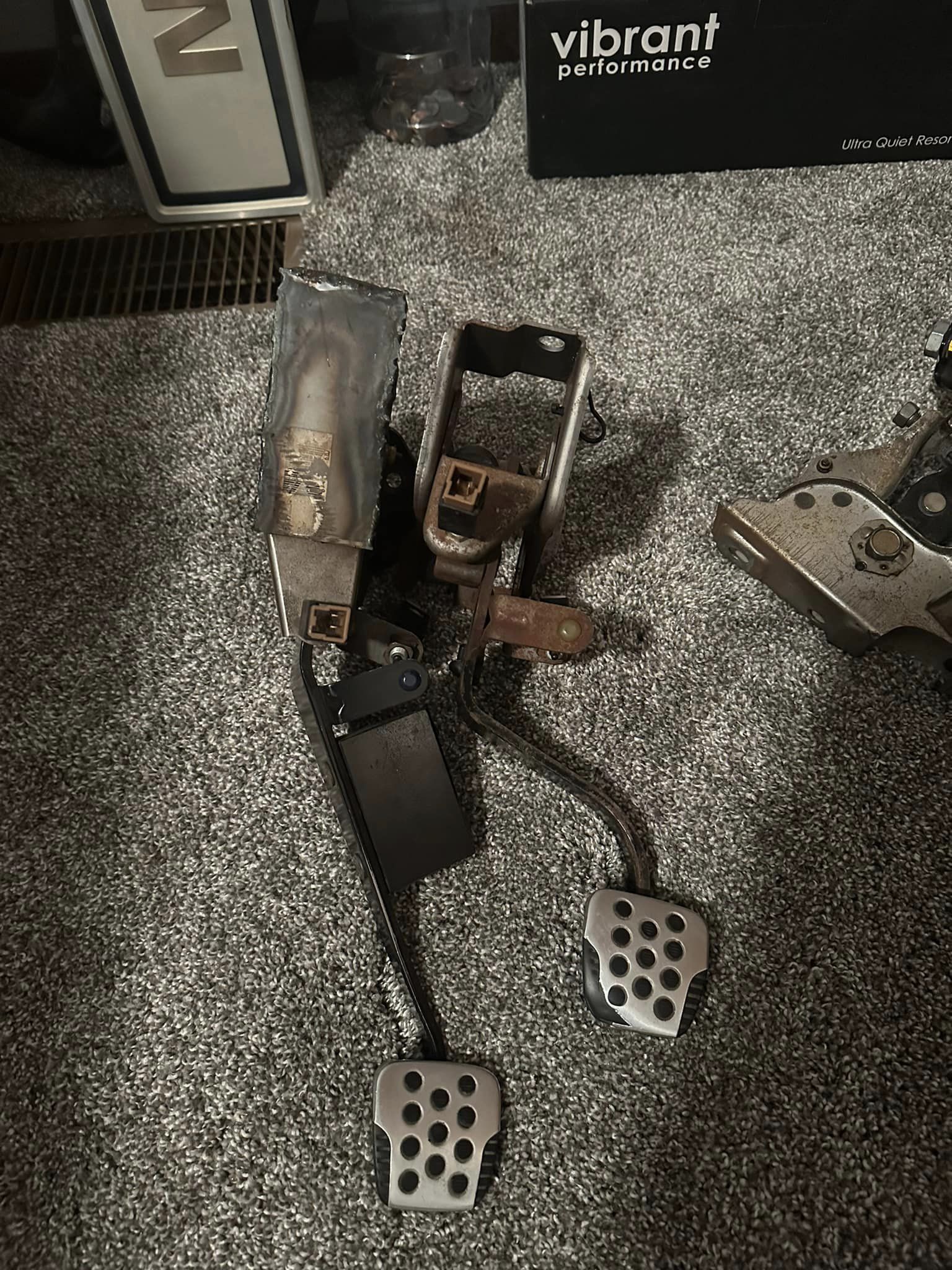
Quick video on throw-out bearings (release bearings) and clutch forks. A local installer recently put one in backwards, which got me digging deeper into how common this issue is.
If your car feels jumpy or jerky when taking off from a stop, there’s a good chance your throw-out bearing (TOB) might be installed backwards. Many people assume this behavior is normal—especially after installing a Stage 2 clutch—but it’s not.
An incorrectly installed TOB can cause bearing wear, clutch engagement issues, and other drivability problems. Make sure it’s oriented correctly during installation to avoid costly repairs later.
I changed my tranny fluid, it was VERY easy. In fact, easier than changing the motor oil (stupid socket won’t fit over the bolt on the oil pan because the ATTS unit is blocking it).
Anyway here goes.
Tools required:
-3 quarts manual transmission fluid (get 3 in case you need more)
-3/8″ drive socket wrench
-17mm socket
-Small attachment pump for the fluid bottles
-Drain plug washer (94109-14000)
-Filler plug washer (94109-20000)
-Something to catch the oil
-Torque wrench (optional but recommended)
-Jack/jack stands
The tranny is located near the front passenger wheel. Here is the pump I used, it was 2.99 from kragen:
Step 1:
Jack up the car. Make sure the car is completely level when raised (4 jack stands recommended). The reason for this is to know how much you fluid you have filled up).
Step 2:
Remove the filler plug.
Use a 17mm socket.
A little bit of fluid should start dripping out.
Step 3:
Remove the drain plug.
As you can see from the picture, the bolt is a little square shaped, a 3/8″ socket wrench will fit right in. Remove it. Be careful, the oil will squirt out pretty far (same with motor oil).
Step 4:
Replace the washers on both bolts.
Step 5: Let the trans drain.
Step 6: Put the DRAIN bolt back on, torque it to 39 N-m (29ft-lb).
Step 7: Attach the pump.
Step 8: Route the tube to the filler hole, pump away!
Step 9:
Continue to pump until filler hole has fluid running out. Stop pumping. Let the remaining fluid drip out.
Manual states:
2.2 US qt at oil change, 2.3 US qt at overhaul for type-SH models
2.0 US qt at oil change, 2.1 US qt at overhaul for base models
Step 9:
Put the FILLER plug back on. Tighten it to 44 N-m (33 lb-ft).
**FYI, you can also fill the transmission through the breather hole on top of the transmission, underneath the air box.
That’s all!
Rebuilding transmissions can get tricky, especially when it comes to special tools. Of course, buying tools is a necessary part of our job. That being said, sometimes getting these tools can become difficult and expensive. In these cases making your own tool is the way to go.
In this article, we’ll show you how to check the fluid level on the JF017E CVT transmission. We’ll use a 2014 Nissan Pathfinder as our test car. This particular vehicle has a filler pipe with no dipstick (figure 1).
We’ll cover three methods for checking the fluid. In all three examples you’ll want to start the engine and put the shifter into each position for five seconds each. After that, put the engine back in park and leave the engine running.
The first method uses Nissan’s special tool: KV311039S0.
Before you check the fluid level use your scan tool and make sure the transmission fluid temperature is between 95°-113°F. If the fluid temperature is not within this range you’ll get an inaccurate fluid level.
Next, raise the vehicle up and remove the overfill plug (figure 2). This plug is located on the lower bell-housing. With the plug removed you should see fluid dribbling out the hole. If the fluid level is low, attach this tool to the overfill plug and pump fluid into the transmission until it begins to dribble out.
Next we’ll use Nissan special tools: J-51155 and J-52611. One is a quick-check gauge and the other is a charge pipe cap release tool. Nissan has a TSB (NTB18-055b) that details the use of the tool.
The great thing about this is that you don’t have to raise the vehicle in order to check the fluid level. The bad thing about it is that it’s hard to find. We tried a local dealer and were unable to get them. We did find them on Nissan’s Tech Mate site for about $260 www.nissantechmate.com, but always check with your local supplier first. Whether you buy the tool or make your own (as we’ll cover next) it’s a great site to have in your collection of bookmarks. Nissan details the use of the tools in TSB NTB18-055b but here’s the gist of it.
As before, you’ll want to check the fluid temperature with your scan tool although this time you’ll want the temperature between 170°-180°F.
Remove the pipe cap using tool J-52611. If you want to save $20 you can release the cap with a small screwdriver instead. Now we’ll measure the fluid with tool J-51155.
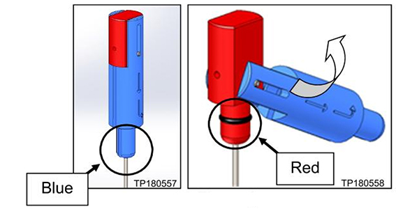
The J-51155 tool is basically two dipsticks in one (figure 3). The handle is both red and blue. The blue part of the handle is a spacer so depending on its position the dip stick will read differently. This gives the tool two distinct depths for the dipstick, based on the model car you’re working on. The chart in figure four shows you which setting to use. The chart also shows you which mark on the dipstick to use for each vehicle.
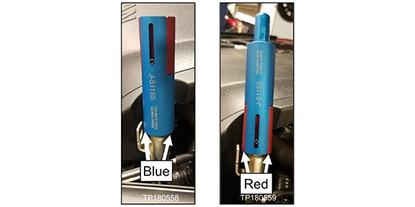
Using the 2014 Nissan Pathfinder as an example and referring to figure 4, you should use the red position handle to measure the fluid height (figure 5). The measured height on the dipstick should be between 14mm-22mm.
If the oil level is low, add fluid and recheck until you have the correct level. The tool makes it easier to recheck fluid levels after driving because you can check the fluid level with the vehicle on the ground.
If you don’t want to purchase the tool, all you need are two spare dipsticks to cut and add measurements to. The filler tube is about 5/8” so when we measure out the dipstick length keep in mind where the tube is going to sit on the dipstick. The measurements are shown in figure six.
Cut two dipsticks to length, one at 25 1/8” and the other 23 1/8” long. From the end of the dipstick lay out the measurements. Mark out 10mm division until you have measured out 60mm. Use an engraver or a punch to label the measurement. The procedure is similar to the J-51155 tool and before you check the fluid make sure the fluid temperature is correct.
That’s it, you just saved yourself a lot of money and have a simple way to measure the fluid level.
Some of our homemade tools save us the most time and money. This one will be one of your installer’s favorite tools in the future.
Steps 1 through 6 will ensure that CVT fluid is properly distributed throughout the transmission.
Models
2013-2018 Altima Sedan
2015-2017 Quest
2016-2019 Maxima
2014-2019 Rogue
2015-2019 Murano
2017-2019 Rogue Sport
2013-2019 Pathfinder
2017-2019 Sentra Turbo
*APPLIED VEHICLES equipped with CVT ONLY
Figure 1
Special tools CVT Oil Level Quick Check Gauge (J-51155) and CVT Charge Pipe Cap Release (J-52611) are now available from Nissan and dealers, Figure 1 and 2. Also, tools can be obtained from Tech-Mate at 1-800-662-2001.
Figure 2
Checking CVT Fluid Level
Steps 1 through 6 will ensure that CVT fluid is properly distributed throughout the transmission. A video on how to use tools is available on nissantechmate.com. Search for J-5261 and then select the Charge Pipe Cap Release Tool.
1. Park the vehicle on level ground (engine running, parking brake set).
2. Using a scan tool, ensure that the CVT fluid operating temperature is within the range of 170°F-180°F (77°C-82°C).
3. Shift the transmission into REVERSE for 5 seconds.
4. Shift the transmission into DRIVE for 5 seconds.
5. Shift the transmission into REVERSE for 5 seconds.
6. Shift the transmission into PARK.
Figure 3
7. Install special tool CVT Charge Pipe Cap Release (J-52611) where shown in Figure 3.
NOTE: The tool shown in Figures 3 and 4 is the same as the one shown in Figure 2, but looks slightly different.
Figure 4
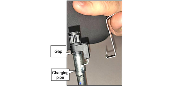
8. Squeeze the tool toward the cap, and then slightly lift the cap (see Figure 3). The cap’s locking tab is unlocked while squeezing. Notice the gap between the cap and charge pipe in Figure 4.
Figure 5
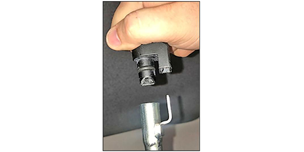
9. Remove tool J-52611 from the cap (see Figure 5).
Figure 6
10. Pull to remove the cap from the charging pipe. Tool CVT Oil Level Quick Check Gauge (J-51155) can now be used to determine the CVT fluid level. The handle on tool J-51155 has two positions, red and blue (see Figure 6and 7). Refer to Table A for the correct position for a given vehicle.
Figure 7
11. With the vehicle in PARK and the engine running, insert tool J-51155 into the pipe. Make sure to use the correct handle position (refer to Table A and Figure 8).
Figure 8
Table A
2013-2018 Altima Sedan (QR25): 23-30mm (blue)
2013-2018 Altima Sedan (V035): 14-22mm (red)
2016-2019 Maxima: 14-22mm (red)
2015-2019 Murano (non-hybrid): 14-22mm (red)
2013-2019 Pathfinder (non-hybrid): 14-22mm (red)
2015-2017 Quest: 14-22mm (red)
2014-2019 Rogue (US. and Japan built) (non-hybrid) : 44-51mm (blue)
In this article I will go over some of the tips and tricks that I have applied in order to keep the automatic transmission from failing, or prolonging it at the very least.
Torque Converter and Fluid
Lets start with the fluid, the transmission fluid is one of the most important parts of the system, it is used to transfer the engines output to the wheels. The engine spins a large drum called the torque converter. The converter is bolted to the flex plate (it is like the flywheel on a manual car), which is connected to the engines crank. The converter has an output in the center which connects to the transmission; this output is physically separate from the housing. An example of how the converter works is when you put two fans facing each other and you turn one on, the other one will spin. Of course the internals of the converter are more complex but it is the same principle.
You can start to see why you are able to have an automatic car in drive while at a stop, yet in a manual car the engine would stall if you left it in gear and stopped. This is because at low RPM’s the converter is not spinning fast enough to cause the opposite side (the output) to spin and propel the car forward, this is called the stall speed; it is the RPM which the engine begins to stall due to the transmissions resistance. Typically on a factory car like the Maxima the stall speed is around 1500 to 2500 RPM. In racing conditions where you want to launch the car as quick as possible, you want to do it from a high RPM. This is when you hear “high stall torque converters” being mentioned. With a high stall converter, the internal fins are modified and angled so that the RPM needed to move the car is higher.
You may think that you can put the highest stall possible but this comes at a cost. The higher the stall the less efficient the converter may be because there is less room for the converter to couple before the rev limit. The coupling is when the input and the output of the converter are spinning at near 1:1 ratio. The lower the RPM the less coupling, the more the RPM the more coupling and more torque is transferred to the wheels. Having the stall too high may give a similar symptom as when you drive a manual with a slipping clutch, you never get the full engagement.
Lock up converter
Torque converters have the option of a lock up clutch that engages using a solenoid on the Valve Body. When this clutch is engaged the converters input and output are locked together functioning just like a manual clutch. With a 1:1 ratio all the engines torque is transferred to the transmission. The ideal torque converter is that which gives you the highest stall possible while coupling still within the engines most usable RPM range. Using the lock up clutch may not be ideal depending on the application; they may not be able to hold the torque on higher HP/TQ. On a high quality converter the coupling should be enough to where a lock up clutch is not needed. Usually the lock up clutch is used by factory during cruising conditions. You may notice the sense of an extra gear when you come to a cruising speed at 40mph to 60mph, this is because the clutch engages and RPM’s drop for better gas milage. Also at wide open throttle with the shifter in Drive and the OD Off (light on the dash turned on), this will keep the transmission in 3rd gear and also lock the torque converter; you can play around this to get a better feel for it.
A 3,000 to a 3,500 stall is usually ideal for most Maxima applications.
Fluid
Keeping the fluid temperature under control is critical. The transmission not only uses fluid in the torque converter but uses it in the entire transmission. Fluid flows through a central location called the valve body. The valve body is what directs the fluid through passages using solenoids to output to the necessary clutches and bands for the selected gear. In factory form, the transmission a has fluid hose output that goes into a bottom chamber of the radiator, exists and then returns to the transmission. This is great to warm up the transmission during cold starts as well as keeping the temperature from overheating by being influenced by the coolant temperature. The problem is that when the torque is beyond what the car came with, you are increasing heat, the radiator’s transmission chamber is not good enough to keep the temperature down.
An external cooler is then required, in my opinion this applies to even maxima’s that are kept in stock form. It is well known that heat is one of the main causes of failures, so why not address it immediately. The external cooler choice varies, I always say to get the largest cooler you can fit. If you live in an environment where freezing temperature are expected it is always a good idea to use a thermostat combined with the cooler.
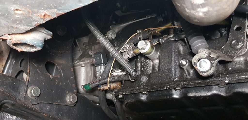
97 Maxima automatic transmission fluid inlets.
In this picture above, you can see the inlet and outlet of the fluid. The large banjo fitting is the outlet and the hard line above it is the return. The hose used is a 3/8th transmission hose.
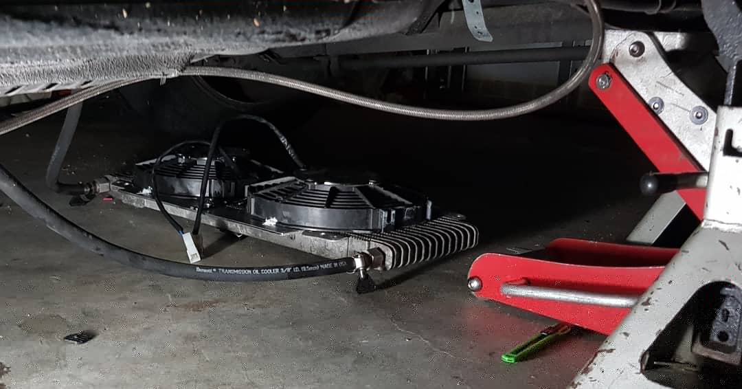
Tru-cool cooler with two spal 9in fans.
The cooler I used is a Tru-cool that is rated for 40,000 GVM (gross vehicle mass) and is generally used in RV and Towing applications. Mounted on the cooler are two Spal 9inch puller fans which I have mounted on a switch using relays.
You can find the cooler and fans on amazon.
Cooler: https://amzn.to/2LJRu8v
Fan: https://amzn.to/30XaTXm
Clutches
Inside the transmission there are severals drums with shafts going through them that spin freely independent from the body of the drum. To help you think about this imagine a rod connected to the engine which goes through a drum. The body of the drum is connected to the wheels. So the engine and the wheels are independent because the engines shaft spins freely. Now if you were to connect the rod with the drum then the wheels would turn. In the drum there is an alternating stack of disks (or clutches. One set of clutches is connected to the housing while the other set is connected to the shaft. When you press them together the friction binds them so the shaft and the drum spin together transferring the engines torque to the wheels. The clutche pack is submerged in fluid which allows for an important function. It keeps the disks from burning by keeping them lubricated and gliding against each other till they are pressed together; rubbing your hands dry vs. rubbing them with soap. This is called viscous coupling, where fluid is used to transfer torque. When you press the plates together using hydraulic pressure, the plates will slip till there is enough force and resistance to make them connect. During this engagement a lot of heat is generated, so you want to engage as quickly as possible to not stay in the slipping stage too long.
Driving Habits
To extend the life of the auto I go by a couple of rules I set myself. Never go wide open throttle from a roll while the transmission is in a higher gear. Putting load on the transmission while it is downshift is very rough on it. It generates a lot of heat because there is more slippage in the clutches. It is better if you manually downshift to a lower gear before going wide open throttle.
When driving and racing I like to keep an eye on the transmission temperature. I like to keep the temperature below 185 at all times. You will notice that while in traffic the temperature will start climbing up, this is because the converter is constantly spinning trying to get the car to move but you are creating resistance by being at a stop; this produces heat. I sometimes prefer to put the car in neutral when at a stop for a long time such as a staging line at the track or traffic.
Modifications
Drop Resistor Mod
This popular modification is also very important because it increases the fluid pressure that the transmission uses internally. This means that the clutches in the transmission are pressed together with more force and therefore providing less slippage and more engagement. Usually factory cars come with a certain amount of slip in order to provide for a smooth comfortable ride, but since we want to go fast here we want the most clamping force possible..
The drop resistor modification is simple, there is a resistor that is mounted on the driver side strut tower in the engine bay on 4th gen and 5th gen Maxima’s, (6th gen perhaps?). When this resistor is disconnected, the transmission then will use 100% of the fluid pressure available. Since disconnecting this causes higher pressure and we want this, you can get a throttle switch that is Normally Closed. The switch can be placed at the throttle or below the gas pedal. You want to activate the switch when you are at open throttle, this will disconnect the resistor. You do not want to disconnect the resistor all the time or at low part throttle because you will have a violent shift that may cause some damage. Note that your overdrive lights will flash when the resistor disconnects at open throttle; the light and code will go away over time and does not affect drivability.
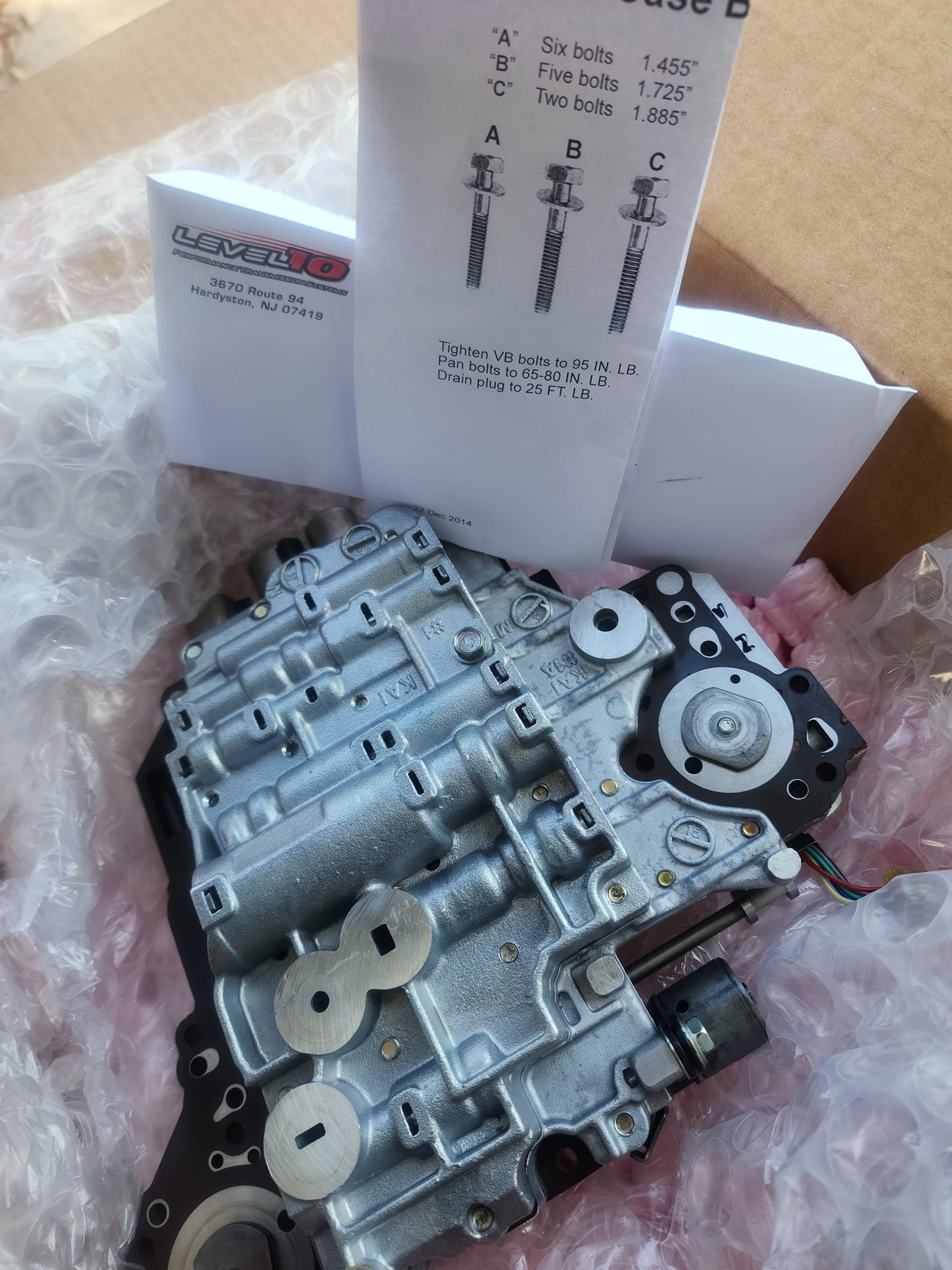
Valve Body
The valve body is responsible for the behavior of the transmission. Attached to the valve body there is a pack of solenoids. In the pack includes two shift solenoids (in the case of the 4 speed Maxima), a fluid pressure solenoid, a torque converter solenoid and and overrun clutch solenoid. When it comes to modifications you have the option to upgrade the VB yourself using a Transgo shift kit. There is the HD and HD2, the later being a more aggressive change in the shifts. There are passages that are drilled as well as ball bearings and springs that are changed to affect the pressure the clutches in the transmission are getting.
Another option is sending the valve body to a transmission shop for them to upgrade, there are common modifications done to automatic performance transmissions so most auto shops should be able to do this.
The solenoids are sometimes also upgraded, they are modified to increase the amount of fluid that flows through them which help add pressure on the clutches and bands.
Internals
The internals of the automatic 4 speed Maxima transmissions which include the clutches and bands mentioned are very good in stock form. I cannot say the same about the 5 speed automatic nor the 5 speed manual. The internals of the transmission can be upgraded by replacing the clutch packs with superior quality as well as the bands. Sometimes more clutches are added to the stack provided the overall height of the stack does not pass the required specs. The clutch in the torque converter can also be upgraded to a stronger material such as carbon so that it has more gripping strength and longer life.
Racing
Lets talk about a turbo automatic maxima and how one can get the best out of the transmission in a drag racing application. You want to take off as fast as possible from a stop. With a turbo automatic you want to have a high stall converter so that the RPM’s required to get the car to move are higher, this allows for the turbo to get enough exhaust flow to generate some boost. So from a stop you press the brakes firmly and at the same time you press the accelerator partly. The RPM’s will start to climb till they reach the stall speed, you will hear the turbo start to wake up. Depending on the stall you have you will be able to generate boost from a stop, then to launch you let go of the brake and go full throttle. Note that this generates an enormous amount of heat in the transmission fluid and causes a lot of wear. This is called Brake Torquing or Brake Boosting on turbo cars.
Another option one can experiment with is using the lock up of the converter during a race. On an all motor Maxima you can lock the converter at the top of second gear and third gear, this varies but is it a general idea and you should experiment with your own application. You want to keep it unlocked in first so that you have the quickest revs and launch possible. Like mentioned before, when you have a good quality and well tuned torque converter you will not need to use the locking mechanism.
Nitrous can be very effective on an automatic turbo car. In my case I have always been a fan of nitrous and have been using Dynotune for many years. I use the nitrous to launch the car without having to brake torque too much. I do not like building up the heat while at the line waiting to take off because then that heat continues to rise as I go down the track. Instead I lightly brake torque to get the turbo spinning a bit then at launch I spray the nitrous.
I thank you for taking the time to read this entry and hope you found it valuable.
So I just took the plunge into my first tranny fluid change and took some pics. I used 5 quarts instead of flushing all of it.
Important Note:Nissan Matic J was replaced with S.
THINGS YOU’LL NEED:
Nissan Matic J transmission fluid (got lucky and found some on eBay but most likely you’ll have to go to a Nissan dealer and pay $15/qt)
10mm Socket
Bucket
Plyers
A friend to help
Funnel
Ramps/jack stands (so you can fit the bucket under)
STEPS:
1. Lift car and remove splash guard.
2. Remove the engine cover so you can get to the charging pipe behind the engine.
4. If you’re replacing X quarts of fluid, fill your bucket with X quarts of water and make a line at the water level. This way you’ll know when do stop draining.
5. Get all your Nissan Matic J transmission fluid opened and lined up so you or you’re friend can continuously pour. Start your engine (nothing will drain without the engine running).
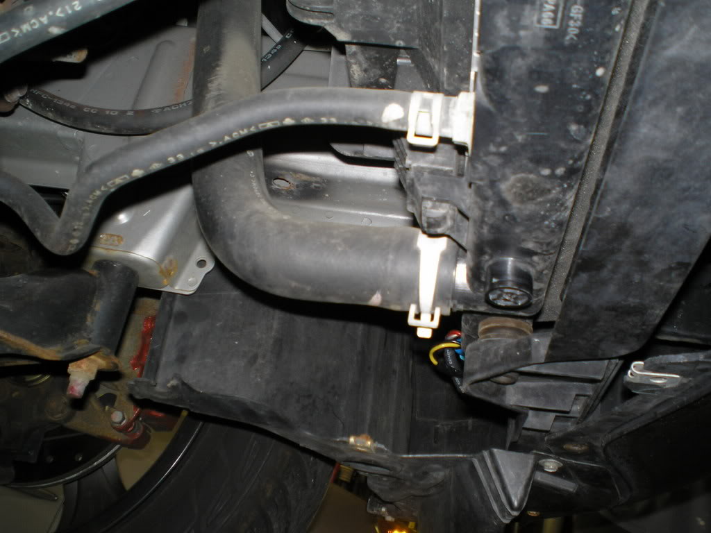
6. Get under the engine with your bucket ready. You’ll be removing the smaller hose from the radiator (see picture).
7. With your plyers, squeeze the hose clamp and slide it farther up the hose.
8. Put your bucket directly below the end of the hose and get positioned so you can watch the fluid level reach the line on the inside of the bucket.
9. Pull the hose off the radiator. I used plyers on this step but it might be easier to just use your hand. TIP: JUST AS THE HOSE RELEASES FROM THE RADIATOR, GIVE IT A PINCH TO STOP THE FLUID FROM SPRAYING ALL OVER YOUR GARAGE!. Otherwise you’re garage will look like this.
10. Yell to your friend to start pouring. Aim the hose at the bucket and stop pinching. Watch the fluid fill the bucket. As soon as it reaches the line in the bucket, pinch the hose again and reconnect it to the radiator. Hopefully all the old fluid is in your bucket and not on your body/garage floor.
11. Slide the hose clamp back to the end of the hose with your plyers.
12. Turn off your engine and give your friend a high five or a kick in the nuts, depending on his performance.
13. Put the splash guard back on. Screw the dipstick bolt back into the charging pipe. Put your engine cover back on.
14. Good work, now go drink a beer and order some more mods for your FX.
Drain Plug
Checking Fluid Level
Important Notes
Actually the transmission holds 10 3/4 quarts. The 30,000 and 60,000 mile services call for a drain and fill which takes about 3 1/2 quarts to do.
OP what I would do is buy 8 quarts, drain the pan, and refill with 3 1/2 quarts. Drive 50-100 miles and repeat the process. Give the car about 1-2000 miles and repeat. That way you don’t shock the tranny all at once with new fluid. I don’t think the tranny has been hurt unless you track your car but check your fluid ASAP. If it is dark or brown and smells burnt, you probably need to ignore my first advice and take it to the dealer for a complete flush and fill.
The tranny fluid is Nissan S-Matic, it replaced the J-Matic and is the only transmission fluid recommended for our engines.
—————————————
I had my tranny fluid changed last month. Me and my buddy did it with the car on the hoist. We used the drain plug on the tranny oil pan. Drained out about 4~6 qts. Then we filled another 4 ~ 6 qts back to the oil pan (depending on how much you drain out). The turn on the engine, with the brake on, shifting from P to R, to D, then D to R to P, each gear stays about the 20 secs to let the new fluid to mix out with the old fluid. Then we did the process again. After that test drive the car in manual mode for about 10 mins. Then measure the fluid level. If not enough, then top out from the tranny dip stick tube with a thin tube funnel.
I do my tranny fluid change about every 30k miles. The car is running fine, no issue with the tranny.
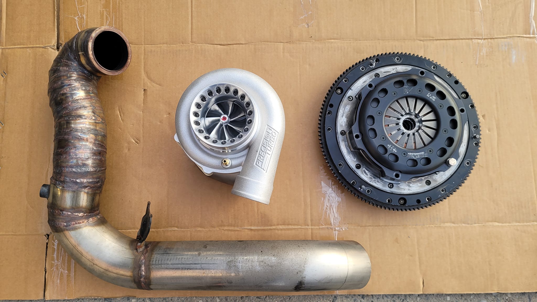
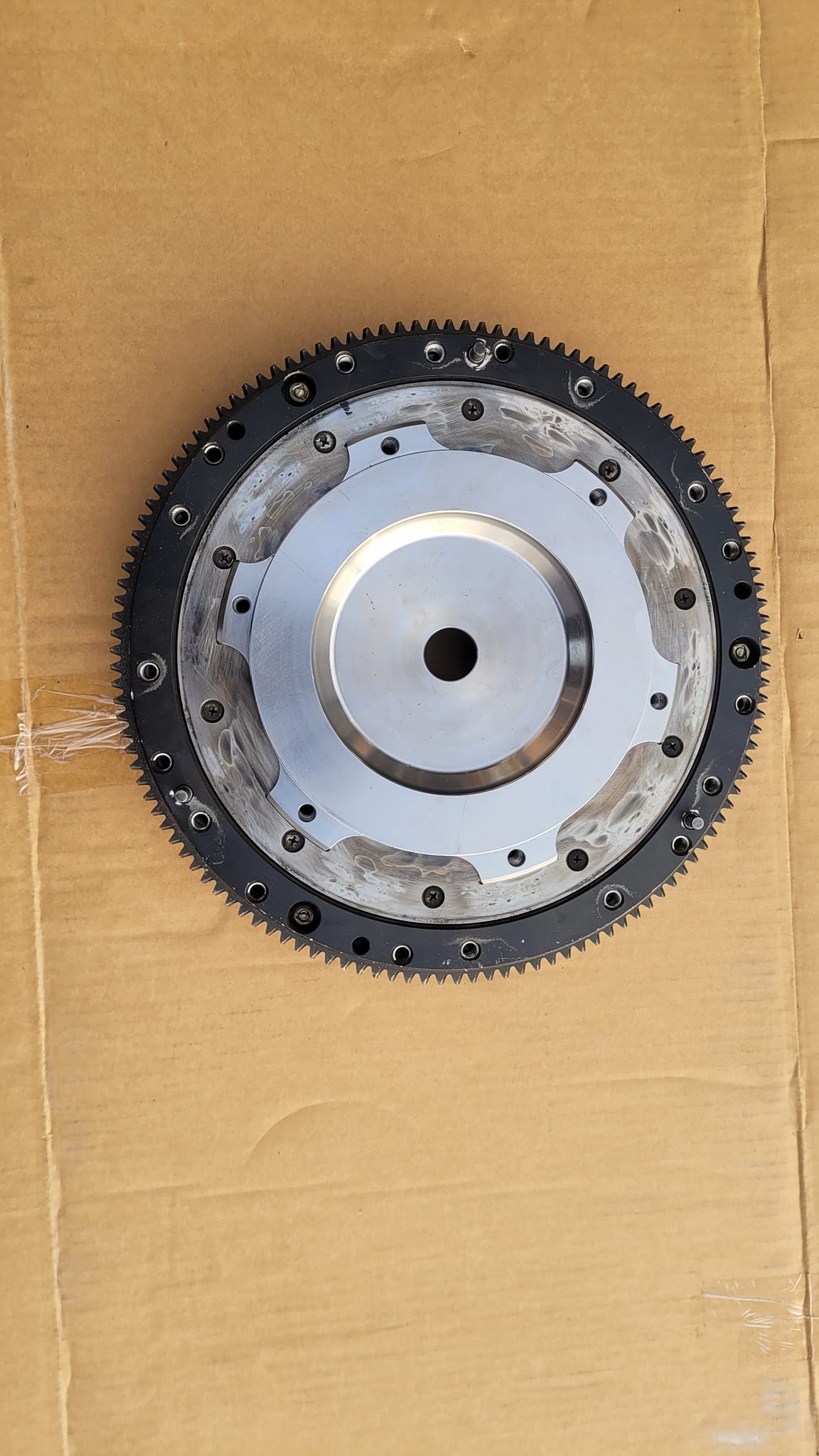
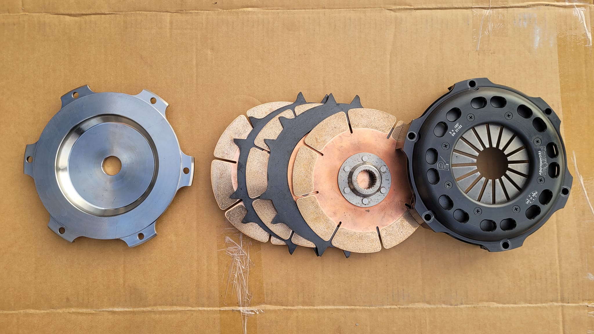
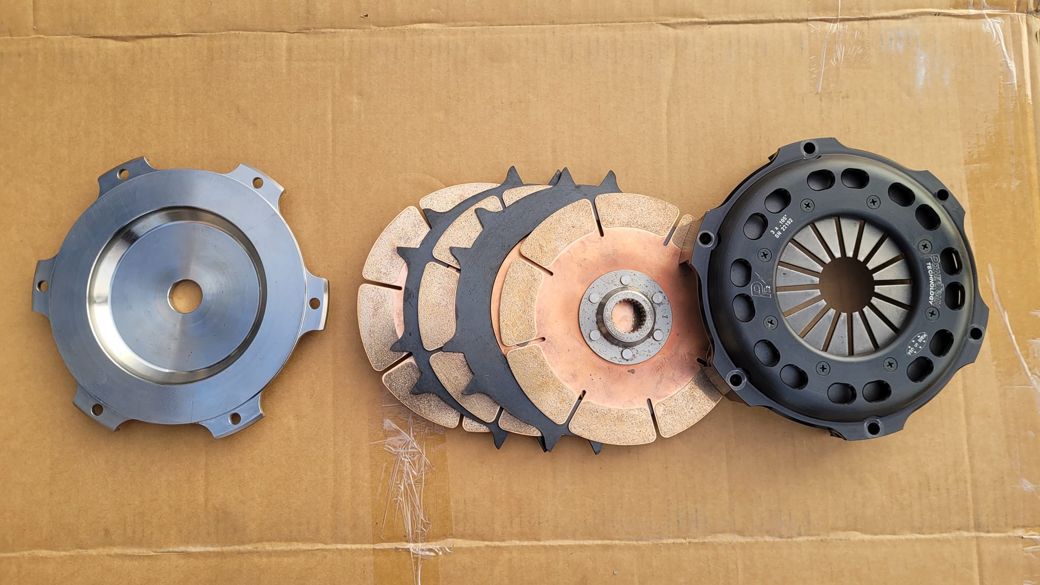
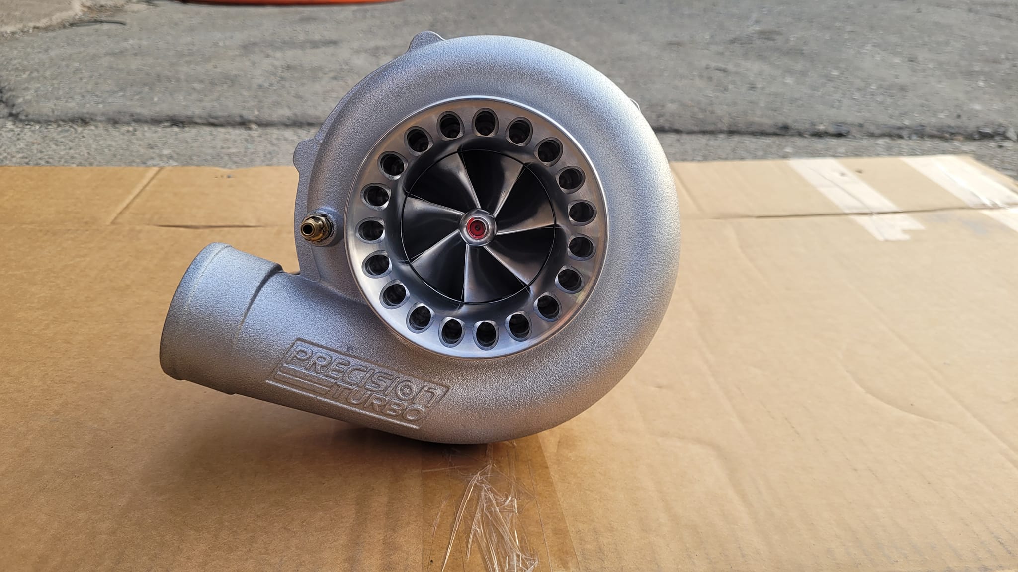
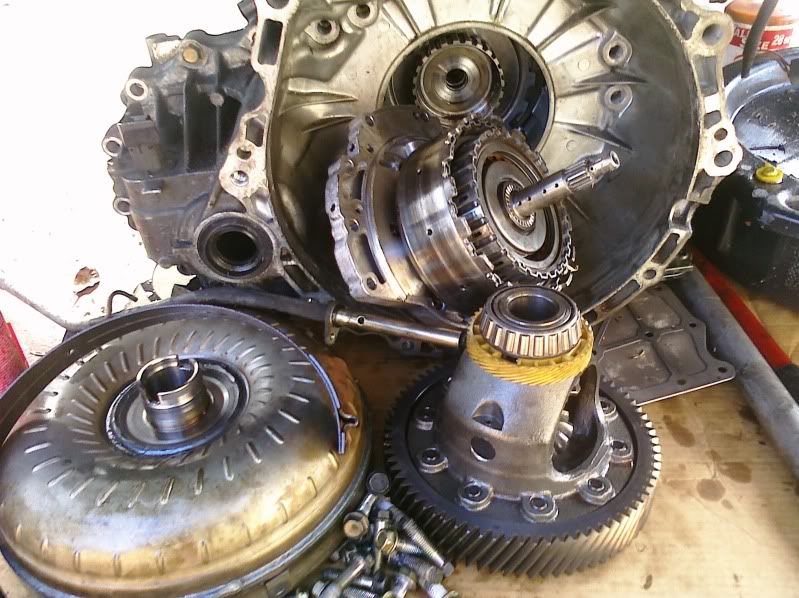
The two limiting factors that prevented us to reach our horse power goal just reach… Triple disc clutch + Gen 2 PTE….. ready to see what this Vq35 is capable of…


")


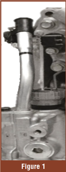
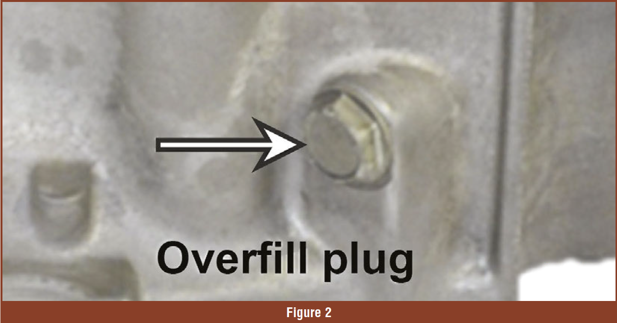
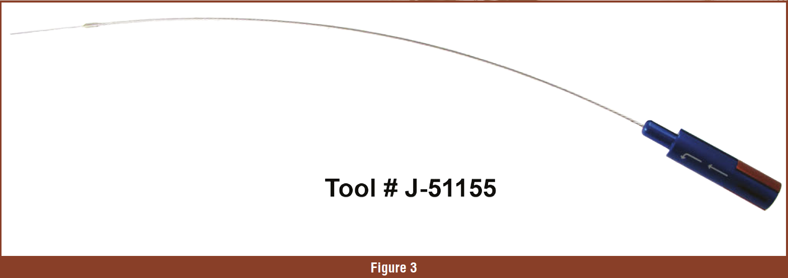
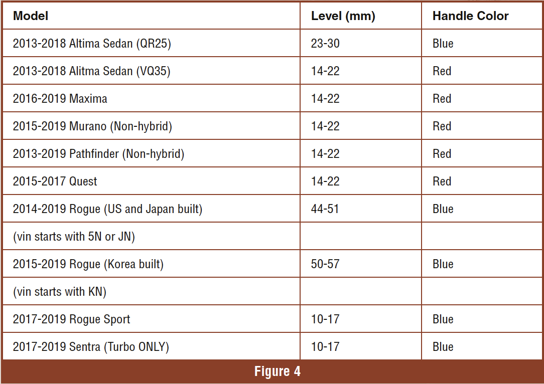
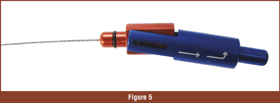
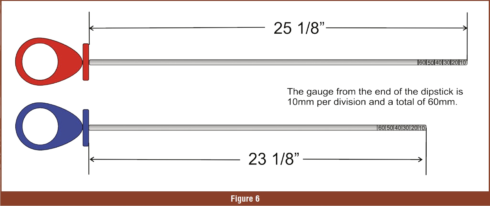


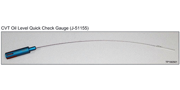
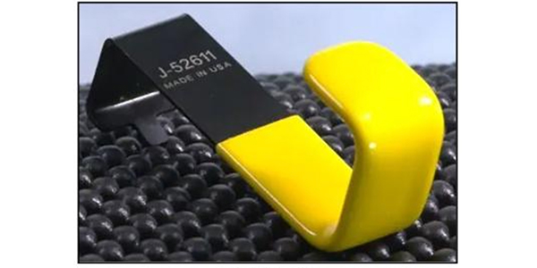 Figure 2


")