These are factory 2015 370z Nismo Edition 19″ forged aluminum-alloy wheels. Produced by Rays Japan for NISMO and Autech.
Size:
- Front – 19″ x 9.5″ +40
- Rear – 19″ x 10.5″ +23
Part #:
- D0C00-3GM3B – Rear 19×10.5
- D0C00-3GM3A – Front 19×9.5




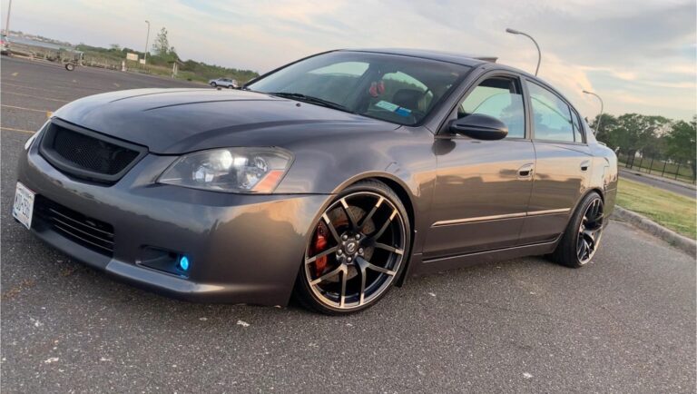
These are factory 2015 370z Nismo Edition 19″ forged aluminum-alloy wheels. Produced by Rays Japan for NISMO and Autech.
Size:
Part #:
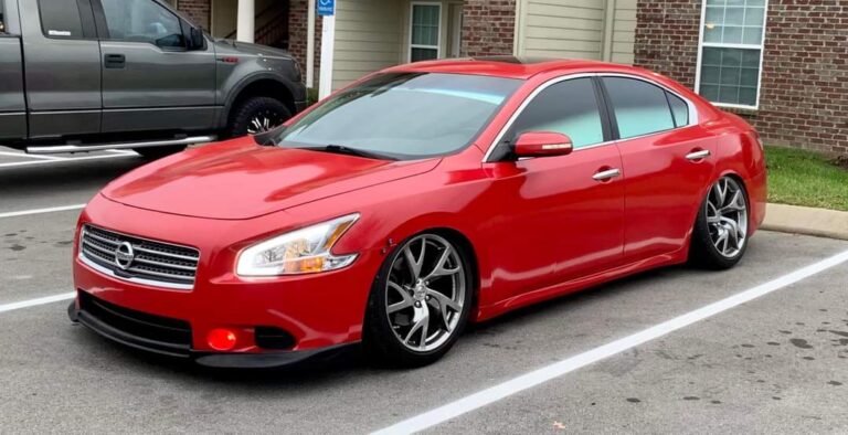

One-Piece Race Spec Strut Tower Bar constructed of strong Aluminum to extremely tight tolerances and then polished to perfection. Designed for the Nissan to decrease body roll, this bar ties the chassis from left to right at critical stress points (Between the shock/strut towers).
As you drive and maneuver, your car undergoes many different forces that the chassis of the car absorbs; the brace helps to absorb the energy and directs these forces into your suspension components so that they can better do their job and serve their purpose more effectively.
A must for any track-driven, and a great addition to any street or show car, this bar truly lives up to the Megan Racing name.
Price: $106.00 – $110.00
Order Links:


Community Member Credit: Shift_Max
Well basically there is a rubber piece that sits in the steering column. Now this is a replacement for that rubber piece. This new piece replaces the rubber piece and provides more direct feeling. The rubber pieces has flex in it when you turn the wheel. This new piece made out of 6061 T6 Aluminum. I have been driving around with this new piece for a long time now and honestly I felt a difference in the way the steering felt and in the way the car reacts.
Here is a picture of the OEM rubber piece that is located in the steering column. Next to it is the aluminium piece however that is the first design that was made. The new version is a little bit different and makes the install alot simpler.

Location of the bushings and what it looks like installed
As you can tell by the date in the picture, I have had this mod for a long time now. Some members have bought them from me as well and their opinions are below
Zero2sixtyZ said “Steering feels more solid and stable. I feel that my OEM bushing was very worn, and needed this mod. No added vibration or anything like that, only benefits.”
Islandmax said “Pain in *** to put in, but is worth it, my stock rubber piece was really worn and soft. Steering is more direct, no added vibrations at idle or in motion.”
Here is a shot of the new design

As far as write-up, this is what I had provided for individuals that have bought the thinner bushings a while back. The process is similar for the new thicker current bushings.
Step 1
Alright some of you might look at the piece and say I have no idea where it goes. Well the piece is located under your dash. If you look at it you see this

You see the black piece behind the pedals ? That is where it is at…
Here is a close-up of it

Now this piece is bolted with Three (3) 10 mm nuts. Remove them.

Once you remove those you would think the piece would come out. Well no it wont because it is a single solid piece. Take a something with a blade and cut it. Now when you cut it I would suggest cutting it on the back side of it so you will not see the piece cut when you look where the pedals are. Now when you cut it, pull and yank on it and it will come out. Reason for cutting it is to
A) make removing it easier
B) Installing it easier
This is what it looks like cut and removed.
You do not have to cut it though since there is enough space to pull the boot up to get to the bolt that holds the column to the steering rack.


This is the view you get when the piece is removed. I already had the aluminum piece installed but on your car it will be rubber. Pictures is the original design of the bushing.

Now the whole piece is held in with Four (4) 12mm nuts. You have to remove each one of them. Also when you are removing them, you will have to turn the sterring wheel to get access to it. It might help to have somebody hold the steering wheel for you when you are loosing it because those nuts are nylon threaded and they are on there tight. I would suggest wearing some gloves if you dont want you hands all beat up. There is alot of metal under there.
Once you remove all those 4 nuts look down and you will see the shaft connected to the rack. There is a bolt that goes straight through. Loosen the bolt but dont remove it. Just enough to pull the shaft up.
Now to get the OEM busing out you have to pull on the steering column towards the driver. But the steering column is bolted down.
next step is to unbolt it… Pictures is installing the bushing on a 4th gen but the same concept goes for the 5th gen.

Once it is removed this is what your car should look like.

Next remove the trim behind the steering wheel. It is held in with screw. This is where the screws are.

There are 6 of them. Once the screws are removed pull the trim off. It will look like this now

Now time to loosen the actual steering column. It is held with 4 nuts. 2 in the front and 2 further back

You can see the 2 nuts in this picture And the other 2 in these next pictures.


Once those 4 nuts are removed the steering column will drop down but be careful since it kinda heavy and there is a bunch of stuff on it
Next you will yank the column towards you and the bushing will fall apart with a bunch of other pieces also.
The next step is to put the new bushing into place. The latest design is a direct replacement so you will only be using the oem hardware.
Once you get the bushing into place, Put the 4 nuts and start them first by hand and then repeat the same procedure you did when you were removing them.
make sure they are tight. If you are not sure you can use some locktite. it can be purchased at any auto parts store.
Once those 4 nuts are tight lift the column up so you an put the 4 nuts back on that held it in place. If the holes dont line up push the whole assembly down. If it doesn’t go down loosen that bolt I was talking about before even more
You can see that bolt in this picture at the bottom
ighten the 4 nuts that held the steering column in place.
Now make sure the 4 nuts on the bushing are tight, the 4 nuts on the steering column are tight and make sure the bolt at the bottom is tight.
Next assemble all the plastic trim behind the steering wheel and under it. Make sure all the hardware goes back into its original place.
You are almost done but now you have to stick that cover back over the shaft of the column. This is a pain i know guys. You dont have to put it back on but you will see the shaft. The easiest way is to align it and open it wider with your hands where you cut it and slide it over and keep working back and forth until you get it to sit the way it was before. That is why I recommend to cut the piece on the back not the front. Once you get it back on tighten the 3 nuts and you are done…..
Take your car for a drive and see how it feels. But please make sure you checked and checked again that all the nuts on the bushing and column are tight.
Well that is a pretty straightforward write up. If you have any questions feel free to ask.
Community Member Credit: Eddy
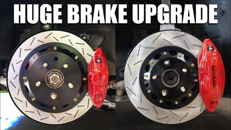
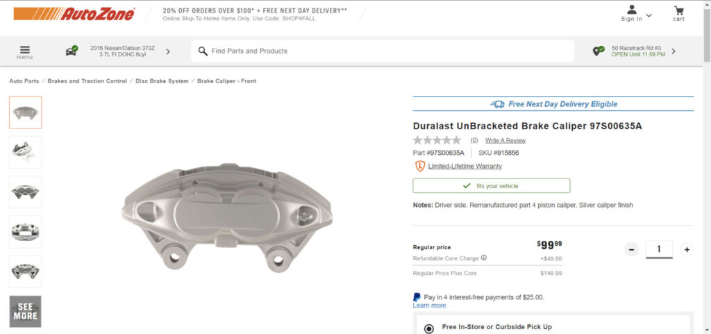
If you are looking to upgrade your Maxima with Akebono’s then check out the deal below at Autozone. You can get both calipers for $200.00 bucks. You can exchange your previous calipers to save the core charge. These calipers work great and are just like the original OEM ones.
Front Driver Side Part Number: 97S00635A
Front Passenger Side Part Number: 97S00635AB
Depending on the Maxima year, you will also need the following:

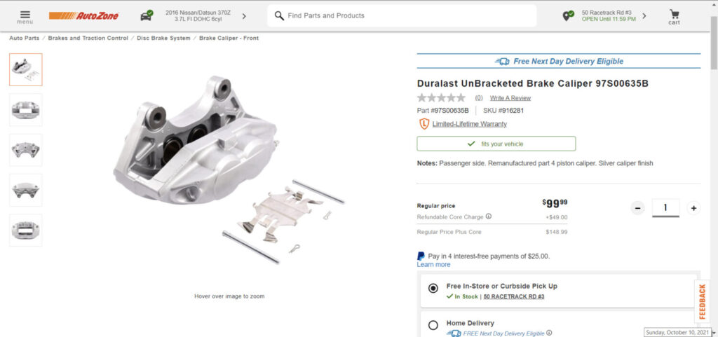
Vehicle Fitment:

Community Member Credit: Robert Mandru
Important Note: These brackets for only for the front calipers. The rear Akebono calipers are plug-n-play but only for the 04+ Maximas/ 05+ SE-R Altimas.
Each kit comes with the following:
Tools you will need:
Due to casting variation of the Akebono calipers, some slight modification may be required to the adapter in order for it to clear the body of the caliper.
Using your 55mm long bolts, thread the adapters to your Akebono caliper until seated. The adapter is mounted to the caliper with the bottom of the “L” shape of the adapter oriented to towards the bleeder while the machined notch sits towards the caliper.
Verify that the notched portion clears the body of the caliper. If it does not, mark the area of contact and remove the appropriate amount of material until cleared. (Take away about 1-2mm of material at a time at approximately a 45-degree angle to match the caliper body angle. Re-mount to verify clearance. Repeat if necessary).

Mount your adapter to your spindle. The adapter sits outside of the spindle mounting holes while the 45mm long bolts mount from the inside of the spindle towards the body of the car. Hand thread one 45mm long bolt by only a couple of rotations. Take your other 45mm bolt and repeat for the other mounting point while extending the adapter away from the spindle. This will allow for extra pitch and play to align your second bolt to the threads of the adapter.
Once both bolts are comfortably thread-started into the adapter, fully thread both bolts through and tighten to OEM specifications.
NOTE: DO NOT FORCE BOLTS ONTO STARTING THREADS OF THE ADAPTER! This may result in damage or cross-threading to the aluminum adapter.
Your bracket will look like this mounted to the vehicle:
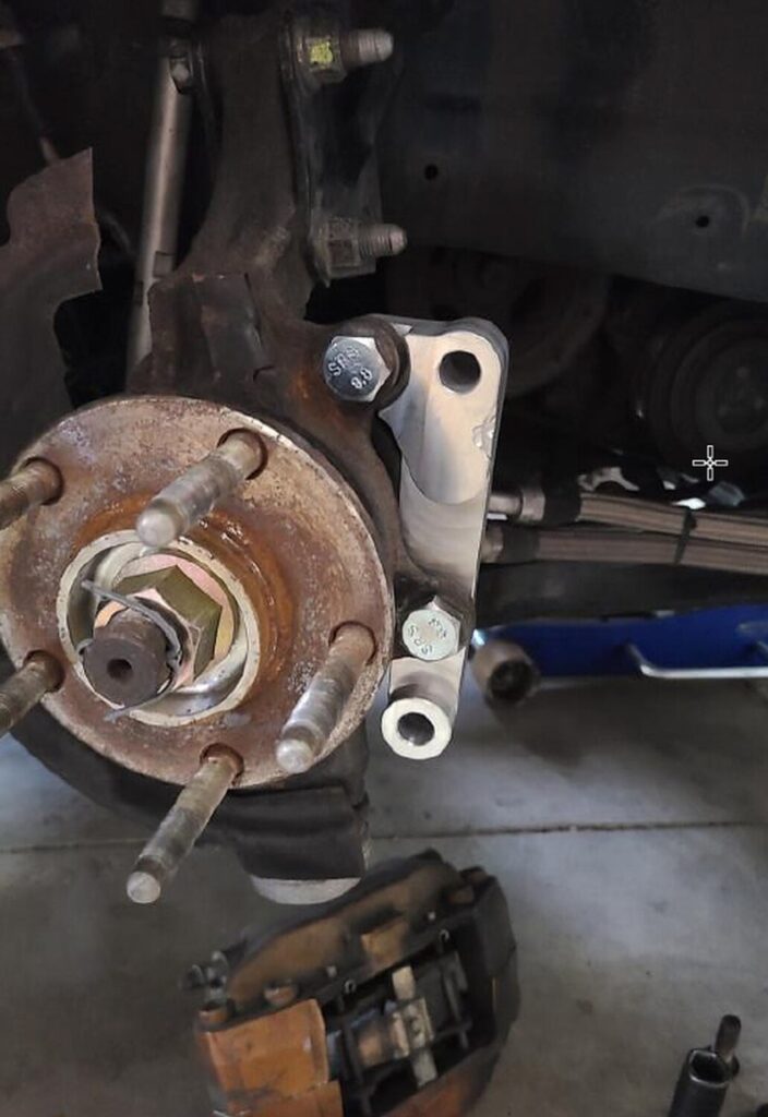
Repeat all steps to the opposite side of your car. Mount your Akebono calipers using the supplied 55mm long bolts. Tighten to OEM specifications. NOTE: Part of the dust shield will need to be trimmed in order for the caliper to be mounted. Use metal shears or a cut-off wheel with the appropriate tool to complete this step.
Double-check all fasteners for tightness prior to driving your vehicle. Test drive and enjoy!
 *** This kit is to be used for off-road use only. No warranty is implied or expressed. Purchaser assumes all liability. Tighten all fasteners to OEM specifications. ***
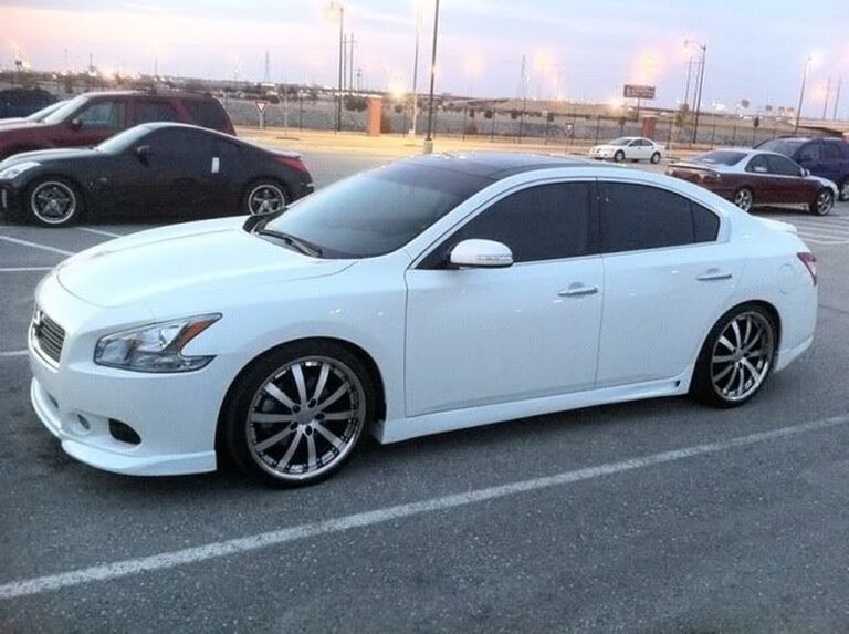
Community Member Credit: bigear82
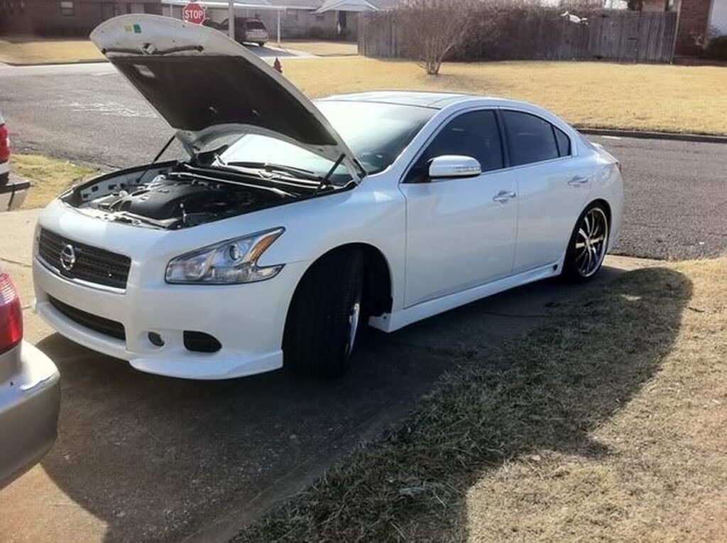
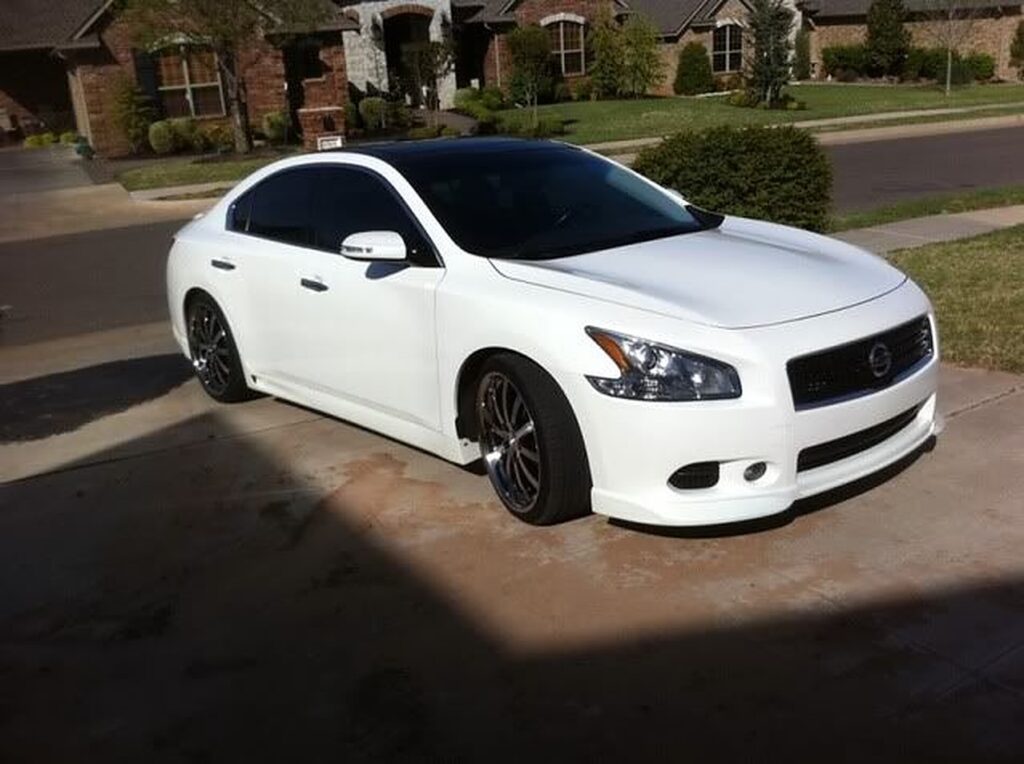
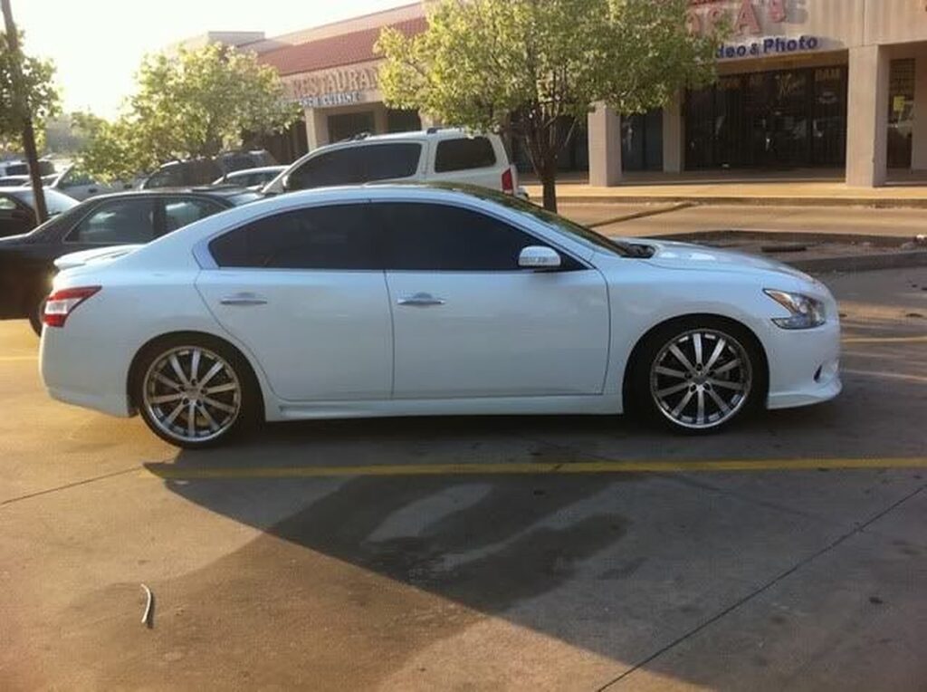
Wheels: Vossen VVS-083 Black Machined 20×9
Tires: Dunlop SP Sport Signature 245/35/20
Suspension: Eibach Springs
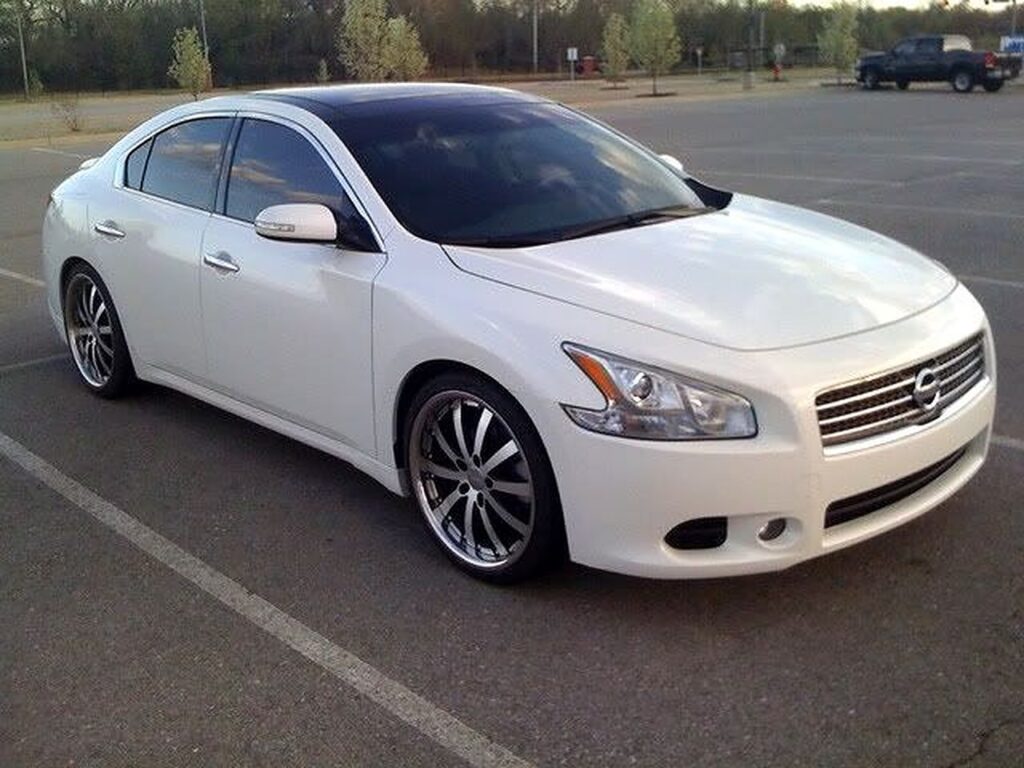
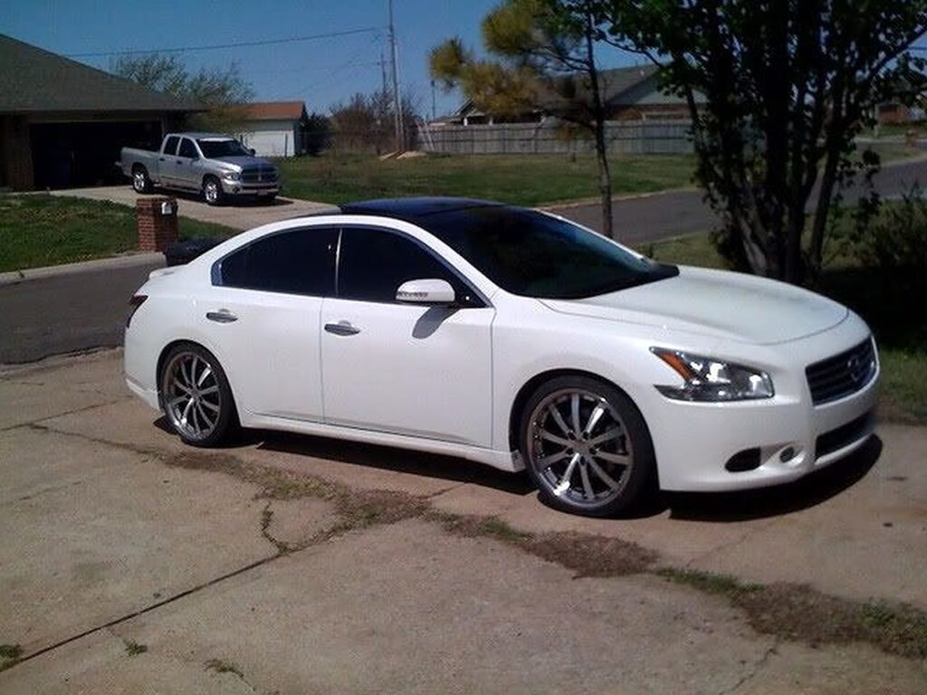
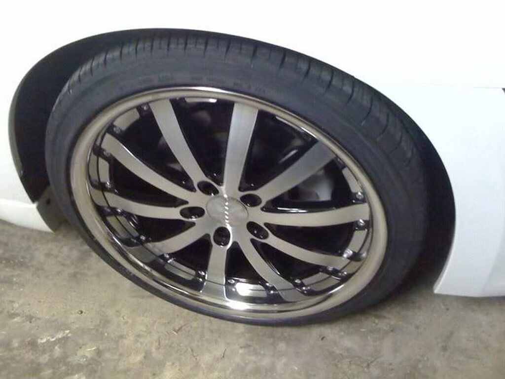
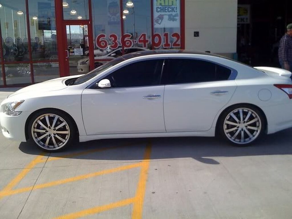
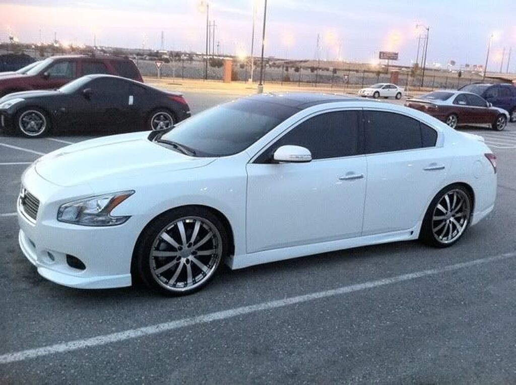

Community Member Credit: Josh Go Hard Neal
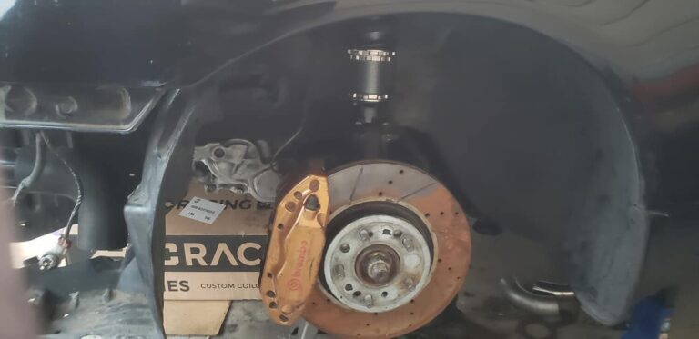
Test fit B15 04-06 Sentra Brembo Calipers and Rotors 4lug re-drilled to 5 lug Edit:(NO Bracket, Direct Bolt-On to Factory Spindle)


Test fit G37 sport 19’s (Front 19×8.5 +43 barely rubs & Rear 19×9 +45 rubs coilover but clears brakes)

Test fit Altima SE-R 18×8 +45 Barely Clears

Community Member Credit: Fezzik
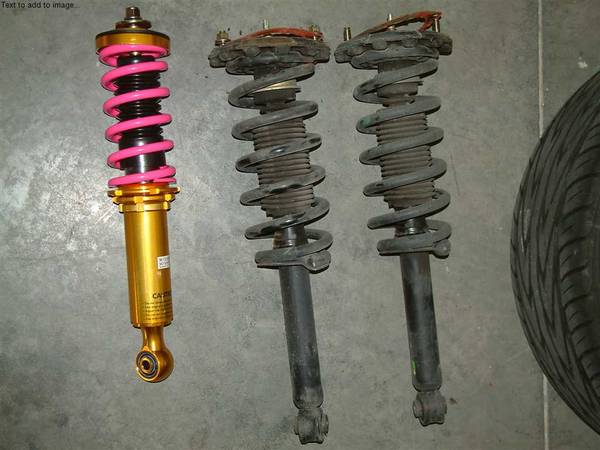
Here is what the rear Coilover that I tested looked like compared to the stock rear suspension. These are still being tested and are not offered yet.
You will first want to measure the car’s wheel gap right now and think of how much u want to lower it by.Be sure to write all your numbers down.
1.) To remove the stock suspension; first, remove the interior sideliner in the trunk.
2.) Jack up the car from the rear and make sure you use jack stands. Then release the jack but barely keep the jack off the rear axle.
3.) Remove the wheels.
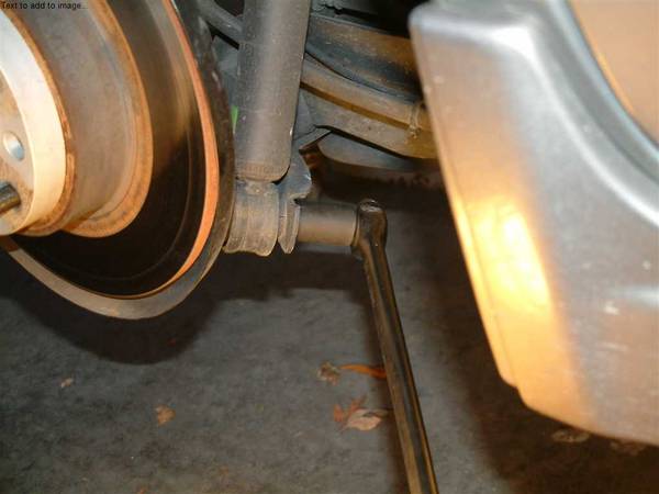
4.) Undo the bolt on the bottom of the stock suspension.
5.) Remove the bolts at the top. There are two of them.Have someone catch the spring and strut when you undo these bolts.
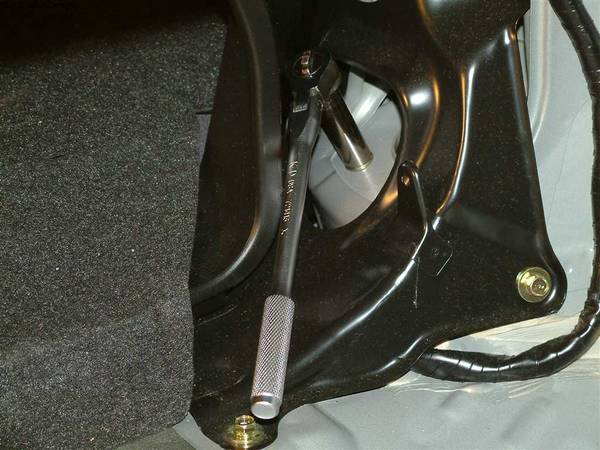
1st Bolt
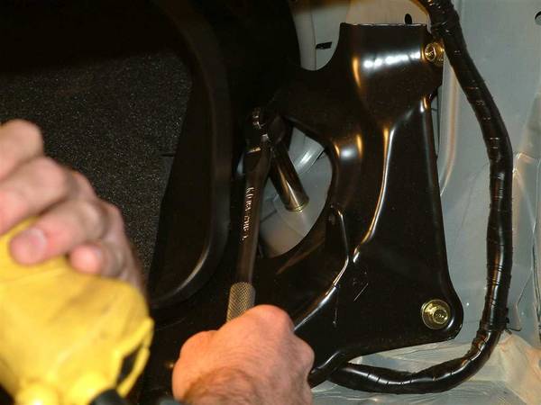
2nd Bolt
6.) Now measure the total length of the stock strut and spring. A good way to measure is from the bottom of the perch (the big black thing at the top of the stock strut assembly) to the center of the hole for the lower attachment. See how it’s done on this coilover.
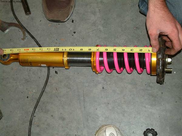
7.) Now disassemble the stock strut and spring. You will need a spring compressor for this job.You may want to hit the bolt at the top of the strut with an impact to loosen it a bit, but don’t remove.
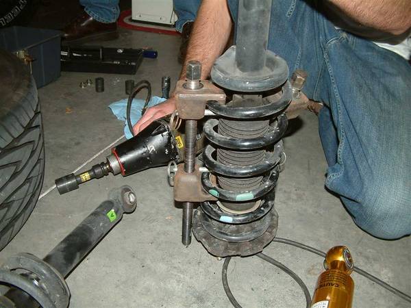
8.) When you have the spring compressed you can remove the bolt at the top of the strut and the top assembly will come off and then the spring.The only thing you want to keep from the stock strut assembly is the big black perch, the bump stop below it and the thick rubber washer above it. This will be used on the coilover.
9.)Now to the coilover. The coilover will come all fairly loose. Take all the stuff off like the spring and dust boot ect. The upper metal washer and bolt will be used again as the very top pieces.You will see a bumpstop here:
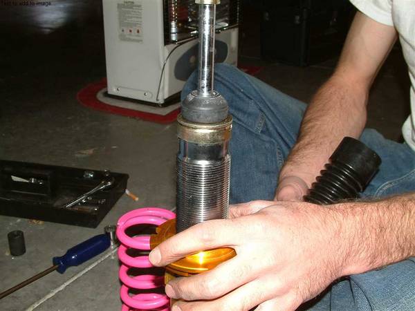
10.)Now make sure there is a washer inside the black dustboot. Put this over the assembly, then the spring and then the bumpstop from the stock strut assembly on top.
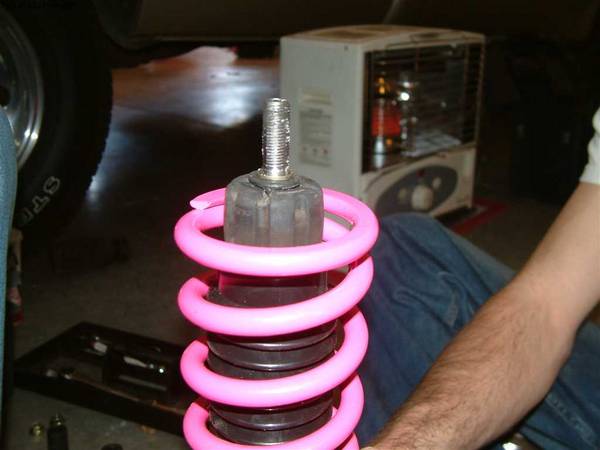
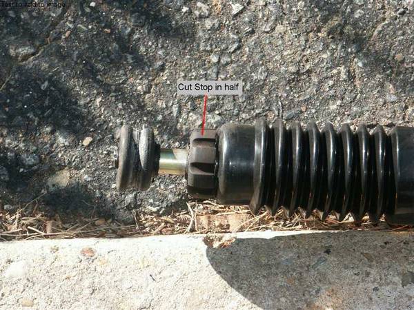
IMPORTANT NOTE: The bumpstop you see in these pictures has not been cut in half. You will need to do this. This bumpstop is made to fit into the perch. If you look the perch underside is designed to the outline of this bumpstop. Look lower for more info.
Below is a picture of the bumpstop cut in half.
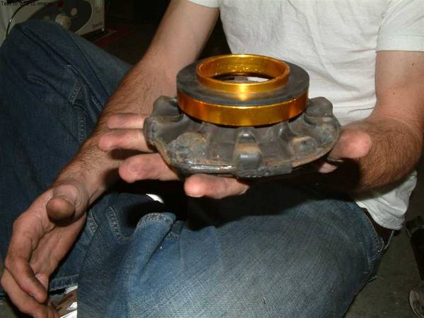
11.) Now there is a gold ring with a rubber gasket on it. This goes on the stock perch like so:
12.) This in turn goes on top of the coilover:

13.) And then install the upper bushing and then metal washer and bolt.
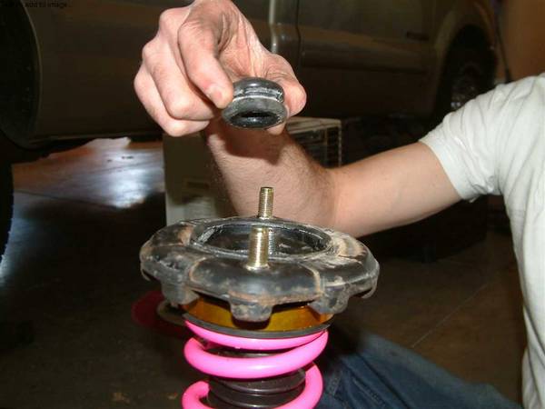
14.)Now if you have an impact, try to impact the top bolt tight. There should be roughly 10 threads sticking out. Look below for a picture of this.Also the bolt is a nylon lock. Mine was tough as heck to tighten. We had to actually cut away some of the nylon away to get the bolt on and then we used locktite.
15.)Ok here is the coilover all put together
Note how the very top bolt has no threads out. This is because the bumpstop was not cut in half. If you cut the bumpstop in half then you will have 10 threads showing through like so:
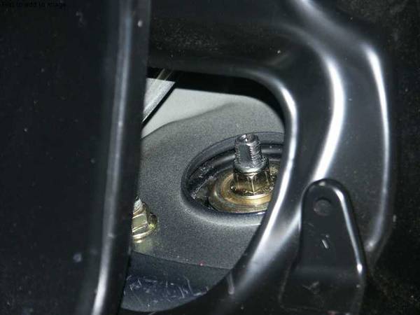
(This is just to show how much threads are sticking out. Don’t bolt up just yet. Measurements still need to be done) (Also make sure flat edge is facing this way)
IMPORTANT NOTE ON INSTALLING COILOVER:When you install the coilover, back install it just the opposite of when you removed the stock strut assembly except for two things. First:If you look down the coilover from the top, you will see that the strut sticking out of the bolt is not exactly round. It has a flat part. Make sure that flat part is facing toward the inside of the trunk and not away.Look at the picture above with the note.Second:The lower part of the strut which you bolt to the car is not perfectly flush on both sides. It will stick out a lot on one side.There is only two ways this part can go into the mounting area.THE PART THAT STICKS OUT MUST STICK OUT AWAY FROM THE CAR. (AWAY FROM THE CENTER OF THE CAR) If not this will rub against the metal brackets that the strut goes in and damage the coilover.
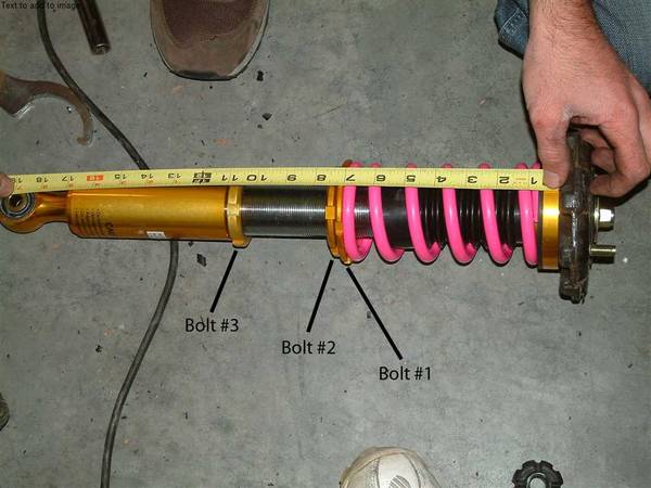
16.)(See below for bolt numbering) Now the coilover is assembled the spring tension needs to be set.You will need to tighten the spring until its just snug. I put it under a little tension but not much.This is done by tightening up Bolt #1 until the spring is under a small amount of tension. (Usually until you can not turn the spring in the coilover.)Tighten up Bolt #2 up to Bolt #1. Make sure this is nice and tight.
17a.)Ok now you need to start doing some measurements.I started out by making the length of the coilover the same as my stock strut assembly. Do this for both sides by turning the lower part of the coilover seen below Bolt #3 until length is right.Install the coilover and wheels. Lower the car.I did two measurements. From the fender well to the top of the rim and from the fender well to the center of the rim.
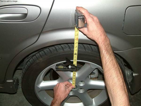
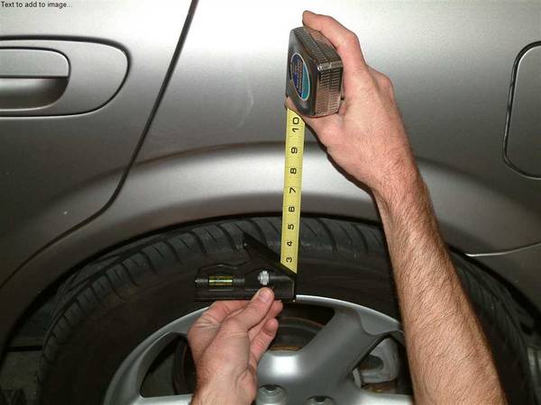
17b.)Now see how much you want more wheel gap you want to take out or add and remember this.Jack the car back up take off each wheel.I was able to make changes by taking apart the lower coilover only and able to leave the top part in place.Turn the lower part of the coilover until you have reached the right measurement. Install the lower part, and tighten up Bolt#3.Make sure both sides are equal. If not just adjust one side to match the other by adjusting the lower part of the coilover only.
Installing the front coilover:When installing the front coilover it’s easy after you have done the front. There is no disassembly or adding to the coilover.Just take out the front stock strut assembly. Be careful with all the lines and cables attached to the front strut assembly. Then measure it in a similar fashion to the rear.On the coilover make sure the spring is barely in tension like in the rear. Turn the lower coilover to match the length of the stock strut. Install the coilover, lower the car, and see how much wheel gap u want to take out or add. Jack the car up and take the coilover off and make the appropriate adjustments to the lower part of the coilover by turning it. When u have desired height, then tighten everything up. Here’s the tricky part. U have to watch out for the lines and cables. This coilover does not have any brackets to hold these. What I did was zip tie them to good structures. But you need someone in the car turning the wheel right and left to make sure it won’t pull these cables and lines.If all is well fasten them down. Drop the car and go get it aligned.You really do not need camber plates. 2002 maxima I know have tons of camber to play with. I dropped my front end 2” and does not need any camber plates.If someone tells you that you need them maybe get second opinion. This is what happened to me. I took it to pep boys and they said I would need camber plates. I took it to a specialty shop in alignment and they got it done is 10 mins.


