Tag

lighting

Browsing

Community Member Credit: IvoRoyfx35Member

Product: JDM VIP style Puddle Light Kit
Cost: $100 including shipping to US address
Tools Needed: Power drill, drill bit, hole-saw, screwdrivers.

Optional: A few fancy tools (see below), relay switch, wire terminal, splice wire connector, extra wires.
Installation time: 4 hours when sipping some beer and enjoying the installation. Probably can be done in 2 hours for you hard-core DIY people.

Warning: Always use caution as you are working with electrical wires. When connecting to the car’s electric wires, disconnect the battery to ensure your safety.

Introduction

So, I’ve seen these puddle lights in person on a Z & Lexus IS and they looked really good. The only concern I had on buying this for my FX was how it was going to look on a car that wasn’t slammed, let alone not even dropped. After many weeks of debate, I finally decided to just take the plunge and go for it. After many hours of research, I decided to go with JDM puddle lights from Elite Auto Style (I have no affiliation with this company). Several things set these apart from the other puddle lights that I’ve run across. These were pre-assembled for easy mounting. The LEDs are made of high quality (based on the reviews I’ve read). The last thing I want is for one of the LEDs to burn out or change color, etc. That would be a major PIA, especially with a flush installation that I was going to do. The lights are focused and do not spread out like some of the other brands. And lastly, it arrives from Japan at my doorsteps in 3-4 days from the date of the payment. How can you go wrong with that?

Anyway, so here’s a DIY on the installation process, and I took lots and lots of pics and tried to be very thorough. Hope you enjoy it as I’ve had a lot of fun doing it and wanted to share it with everyone.

Instructions

1. So I got the package and this is how the puddle lights came in the box. Nice chrome plates and the led bulbs had a thick coating of some sort, I guess for extra protection against rocks and all that good stuff on the road.

001_pd.jpg

2. Back of the puddle lights…This is what I mean by pre-assembled. Some of the other lights I’ve seen online didn’t have these housings with screw nut for an easy flush install. Some just comes with 3M mounting tapes (Ewww). Now back to the ones I got, you can choose to use the mounting brackets that come in the box. I wanted a flush install because I don’t want anything sticking out of the side skirts as well as exposed wires.

002_pd.jpg

3. Side Skirt Removal – Remove the screw located at the rear of the side skirt. I used this fancy tool that my friend had, but if you don’t have it you’ll need to remove the rear wheels because the space is too tight to work with a screw driver.

003_pd.jpg

4. Remove these 5 screws located underneath the side skirt.

004_pd.jpg

5. Remove this screw connecting the side skirt to the front mud flap.

005_pd.jpg

6. Remove the three screws behind the front mud flap and the mud flap should just fall off of the car.

006_pd.jpg

7. Pry apart the side skirt using a flat screw driver (cover with towel if you want, I didn’t and it was fine). I found that starting from the back of the side skirt (near the rear tires) was the easiest in taking these off. You’ll need to apply firm but gentle pressure. Once you pop the first two clips off, the rest will pop out pretty easily.

007_pd.jpg

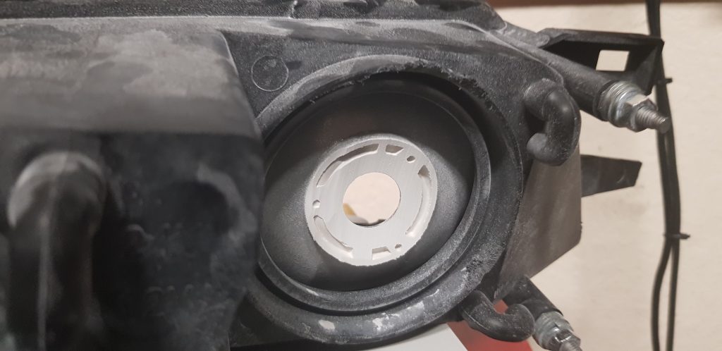
8. Here is the clip ‘housing’ that is on the car.

008_pd.jpg

9. Here is the clip ‘insert” that is on the side skirt. Sometimes, it helps to use a thin screw driver to push down on this clip insert so you won’t break the clip housing when prying it apart.

009_pd.jpg

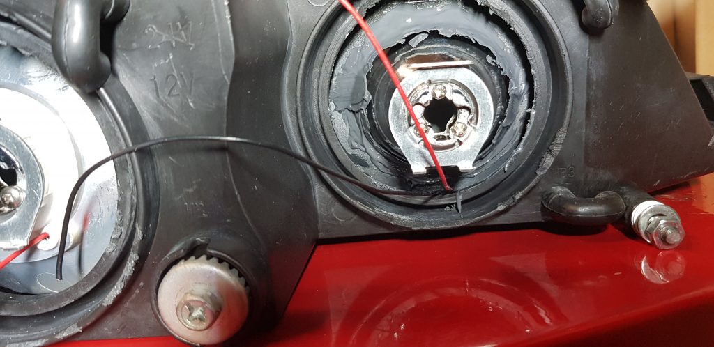
10. I still managed to break a small part of two clip housings (red arrow)…But the skirt went back on fine and there was 0 rattle so don’t worry yourself too much if you break these.

010_pd.jpg

11. Now comes the fun part for all you math wizards. Mark the side skirt so that each light has equal distance from each other and from the front and rear ends of the side skirt. You can measure the length of the side skirt and do some crazy math formula and figure it out yourself. For me, I just made sure that the distances between the lights were equal and the distance from the edge of the skirt was equal. Make sure that you are marking on a place that will be parallel to the ground once the skirt is back on the car (so the light reflected on the ground maintains the circular shape) and also make sure that your marks are in A STRAIGHT LINE!!! If not, they will look staggered on the ground.

011_pd.jpg

12. Once you’ve made all five marks, drill a small pilot hole.

012_pd.jpg

13. Select the right size hole-saw and drill through the pilot hole from the OUTSIDE. I think I used a 3/4″ hole-saw, but make sure you measure your light base and drill appropriately. You only get one chance. (The hole can be slightly bigger than the base since there are tightening nuts for these lights.)

013_pd.jpg

14. VERY IMPORTANT – Before doing anything else, grab yourself a cold one and pat yourself on the back for having gone this far without breaking anything.

014_pd.jpg

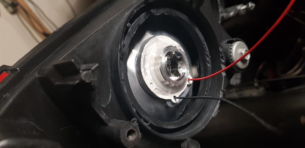
15. Insert the puddle lights through the hole and tighten with the provided nut.

015_pd.jpg

16. Connect the red wires together and do the same for the black wires.

016_pd.jpg

17. Your packet should have 2 of the 10 lights that have only 1 red / 1 black wire connectors. These will go to the end of the side skirt. If you only have 1 or none with single connectors, (I only had 1) don’t panic! You can just tape off the ends with electric tape and you’ll be good to go.

017_pd.jpg

18. All lights are now connected and exposed metal connectors covered with the rubber transparent cover. This is important as you don’t want any part of the red connector touching the black connector when the lights are on.

018_pd.jpg

19. Put the skirt back on with the red/black wire ends out. Remove the side kick panel.

019_pd.jpg

20. Remove the door step and say hi to the dried out bug that somehow managed to get in there.

020_pd.jpg

21. As with the side skirts, gentle but firm pressure should pop the door step out without breaking the clips.

021_pd.jpg

22. Now, before screwing the skirt back on, test out the lights. I used the battery of my drill to temporarily power the lights. Then, remove the remaining plastic parts near the side kick panel and lift up this black rubber/foam liner so you can put the wires through them and continue the CLEAN installation.

022_pd.jpg

Follow the above steps for the other side.

23. Use the provided extra wires to connect the left side of puddle lights to the right side of puddle lights.

023_pd.jpg

24. I used a flashlight to figure out where I can make the connection (underneath the dash).

024_pd.jpg

25. A-ha!

025_pd.jpg

26. I used another one of my friend’s fancy tools to carry the wire through this opening. But a coat hanger will do the trick just as well.

026_pd.jpg

27. Connect the wires and tuck them in under the carpet.

027_pd.jpg

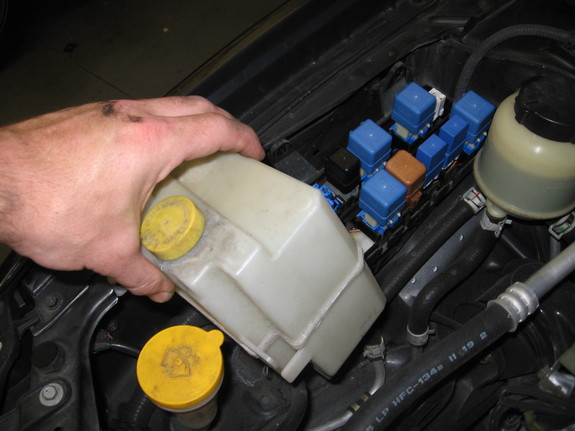
28. Back on the driver’s side, cut the extra wires off and join the red to red & black to black. You can try to tap the conjoined black wire to the ground wire in the fuse box, but I just decided to ground the wire to the metal frame of the car (wire terminal sold at radioshack).

028_pd.jpg

29. Now this is where you can go off on your own. You can certainly use the provided switch to create a switch that you can use to turn on/off the puddle lights, or tap into any 12v source such as side kick door lights, parking lights, etc. As for me, I wanted to tap into the doom lights. Then, the puddle lights will come on when I press unlock and go off when I press lock with the remote. It will also go on when the doors are open and go off a few seconds after the door is closed, as with the doom lights.

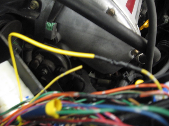
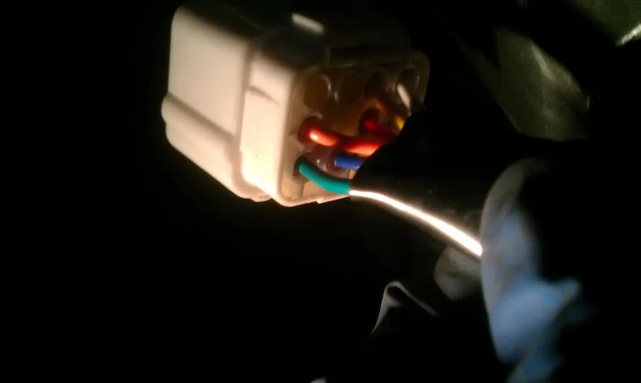
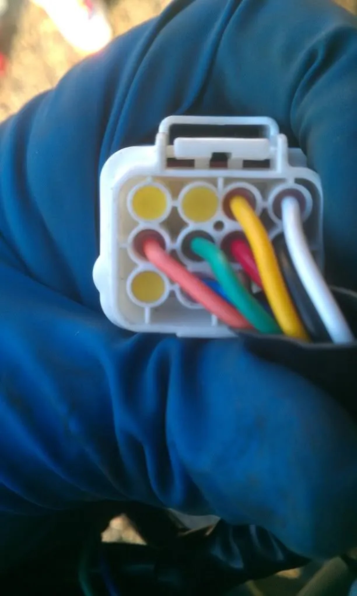
In order to do this, create a relay switch (radioshack) similar to the one shown here. I don’t know too much about wiring so my friend did this part for me, but it seems pretty simple. Put the red wire into the relay switch, make a loop with the white wire, and take the other white wire to the fuse box. Also take the blue wire to the fuse box to tap into the dome light wire.

029_pd.jpg

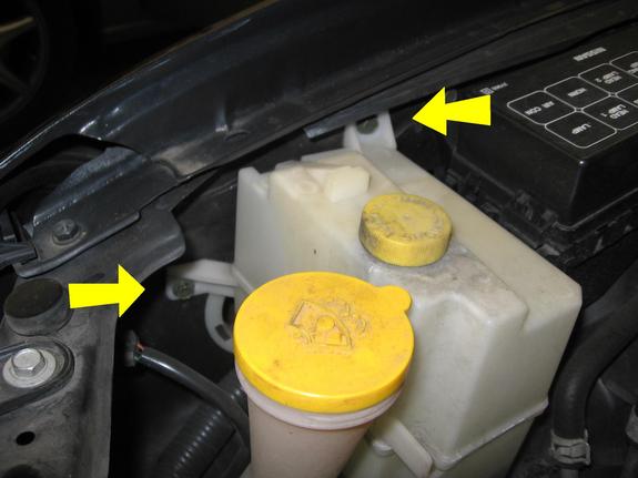
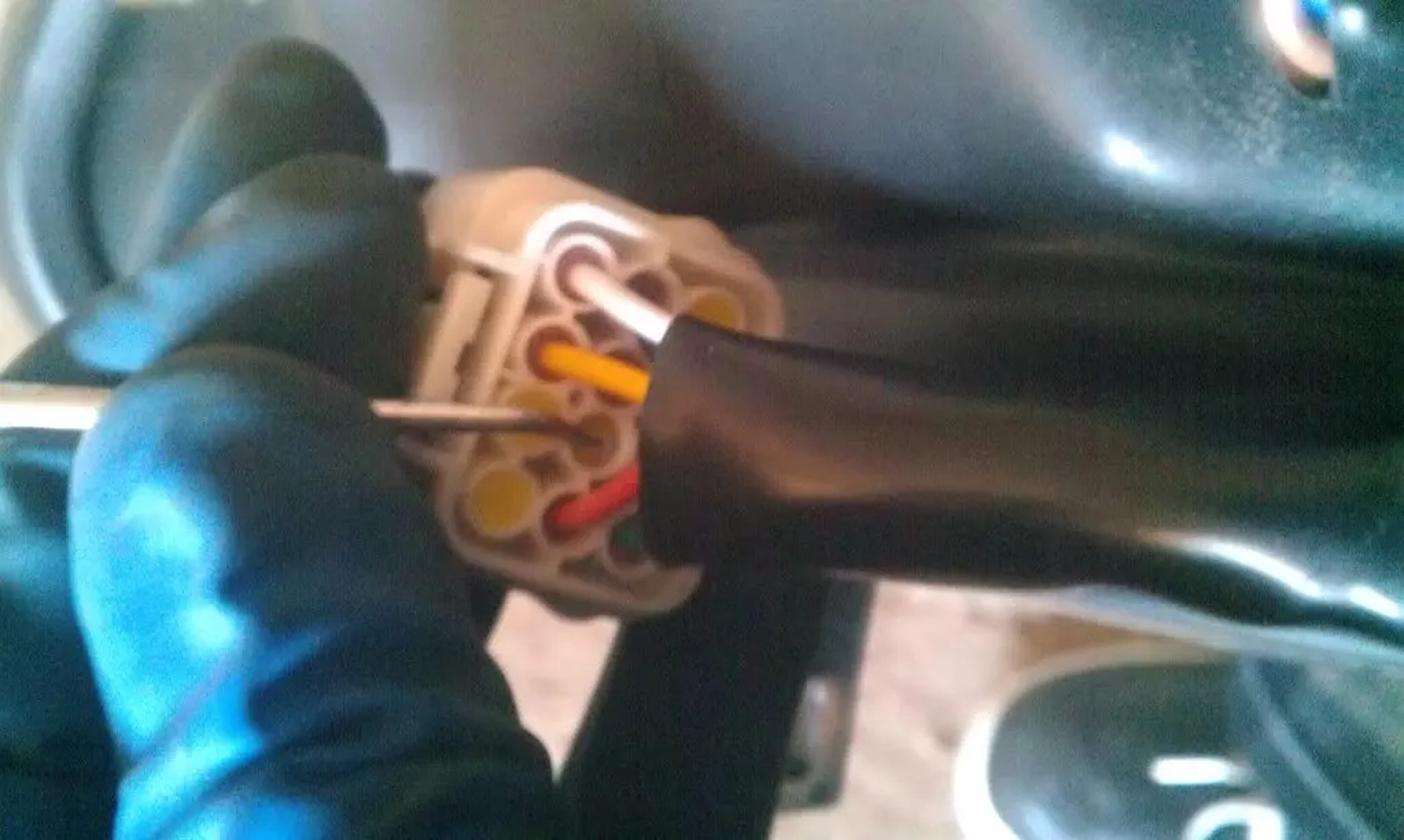
30. Tap the white wire to the red wire shown.

030_pd.jpg

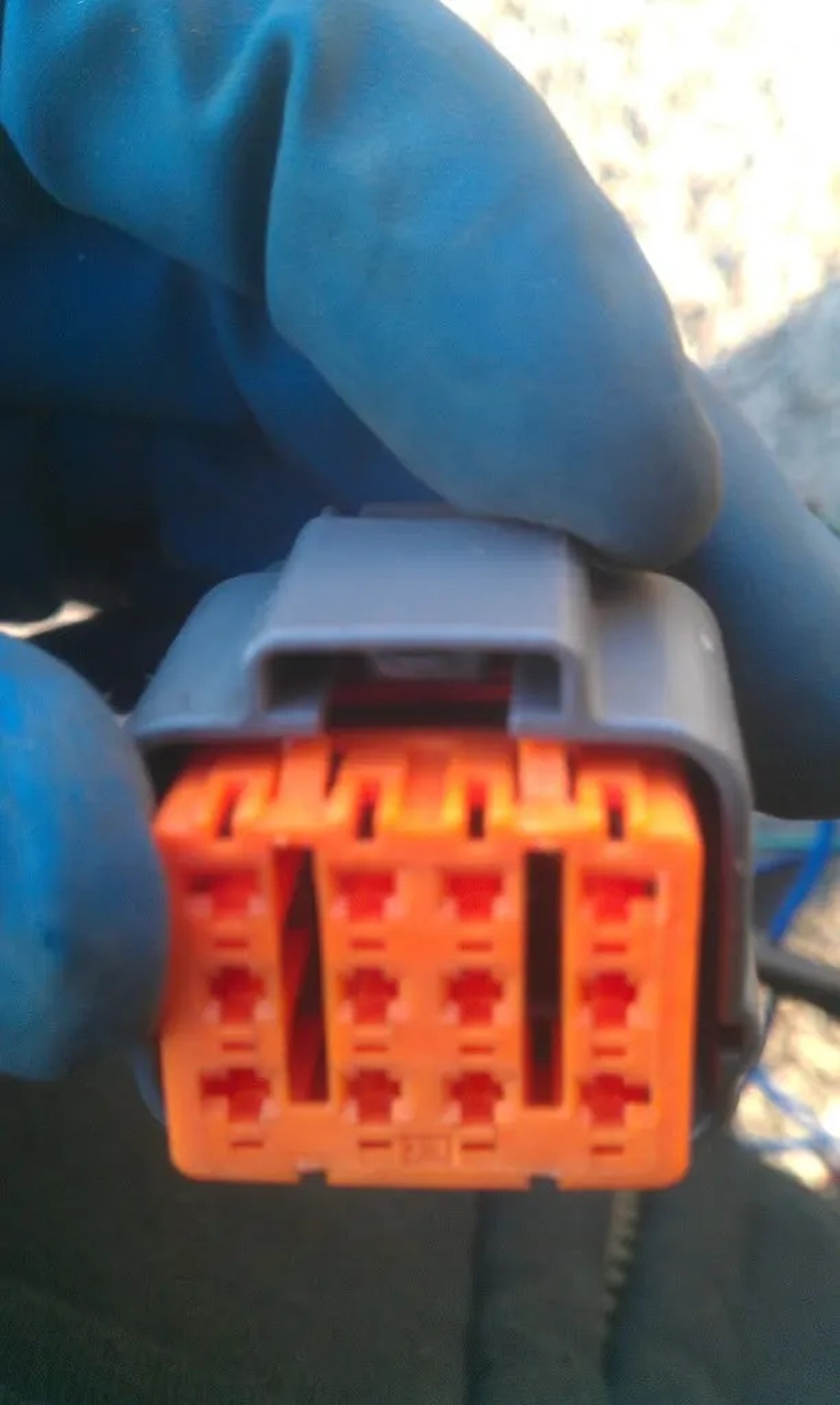
31. Tap the blue wire to the purple/white wire shown. The purple/white wire is the dome light.

031_pd.jpg

32. Make sure no wires are exposed and the newly created connections properly taped off with electrical tape / zip tie. Put everything back on.

032_pd.jpg

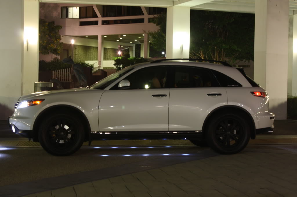
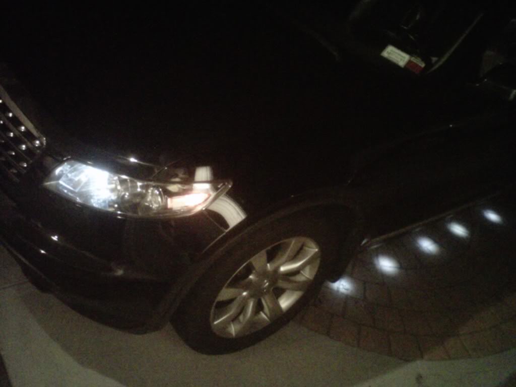
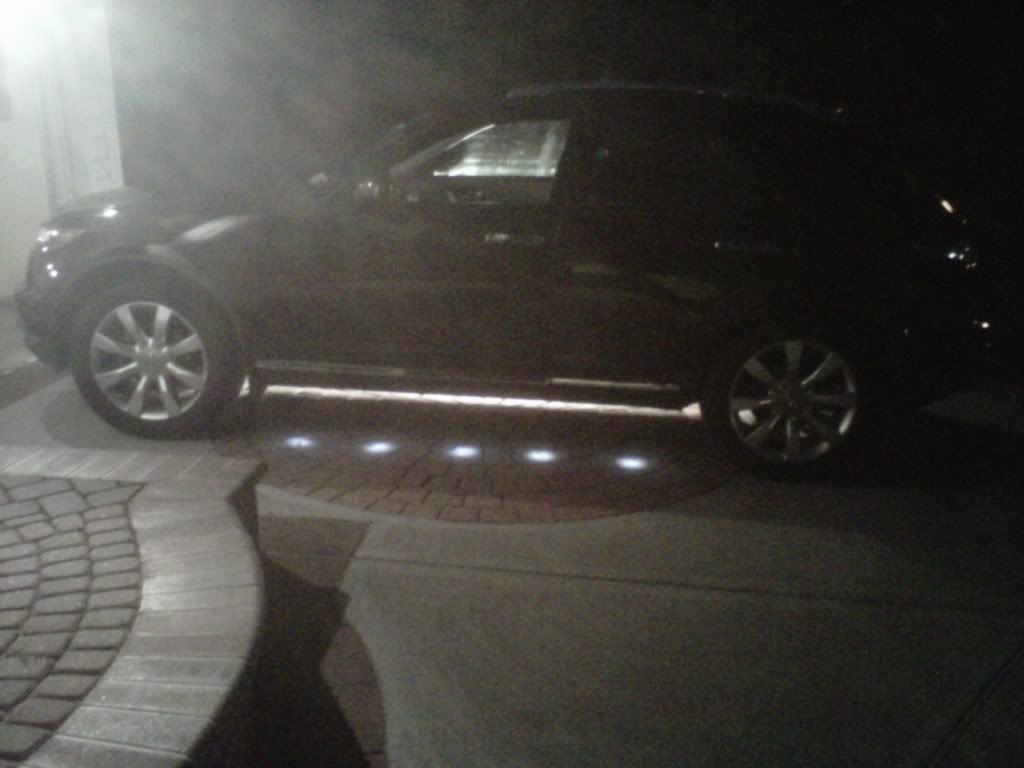
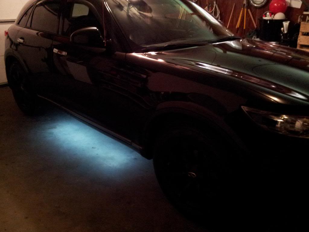
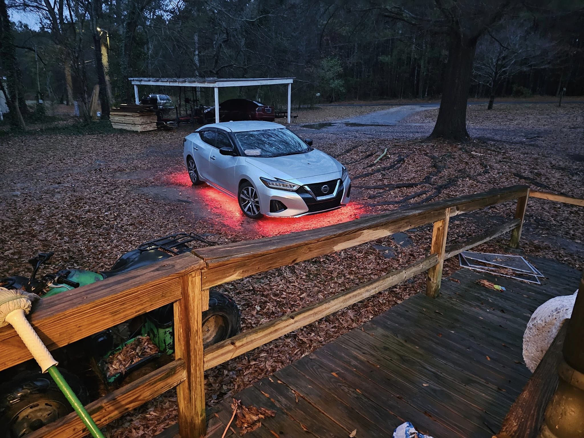
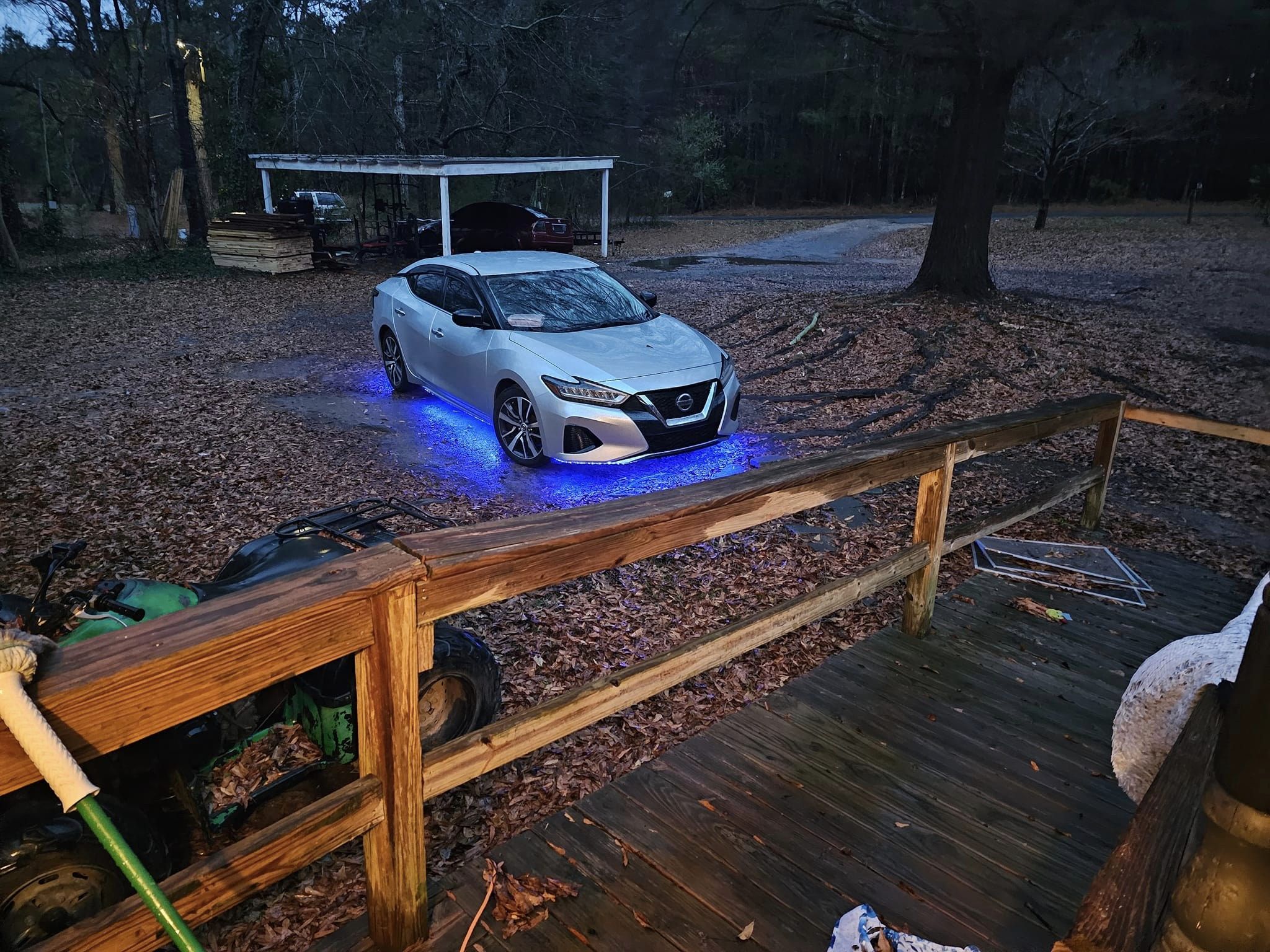
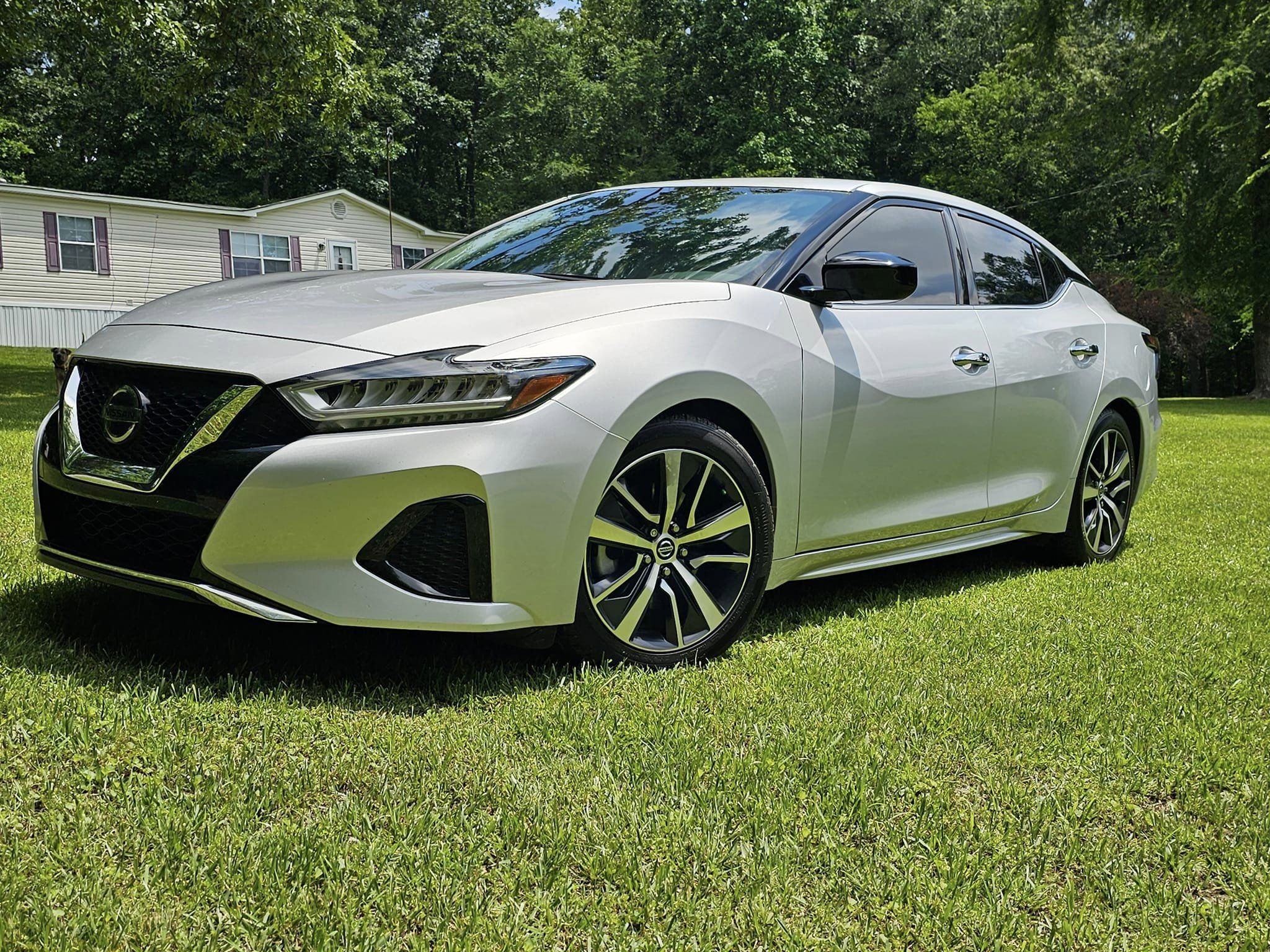
This is how each puddle light looks with the flush install.

033_pd.jpg

034_pd.jpg

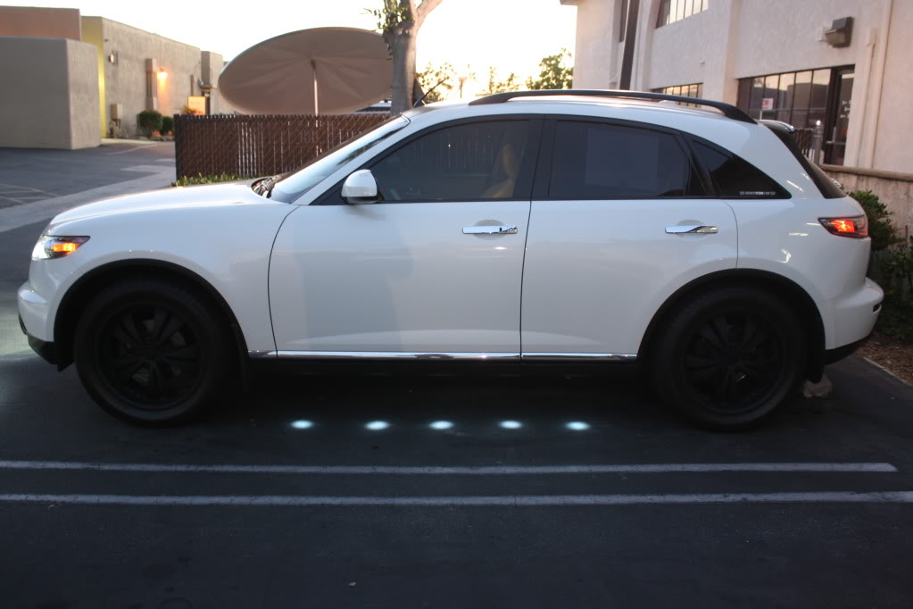
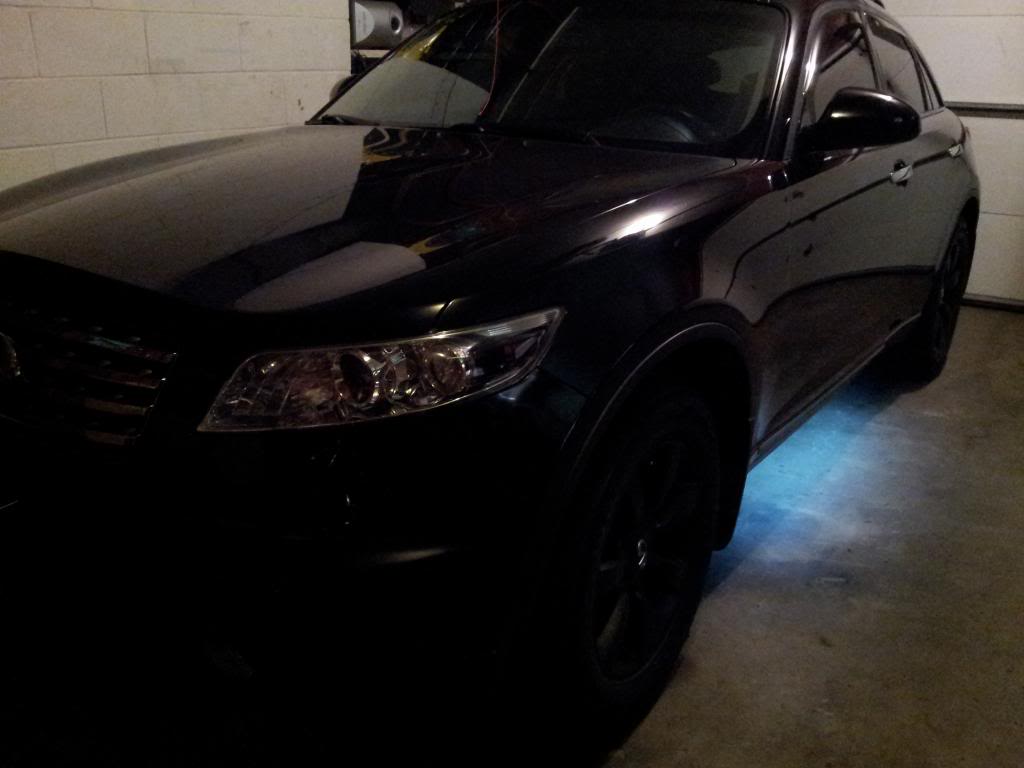
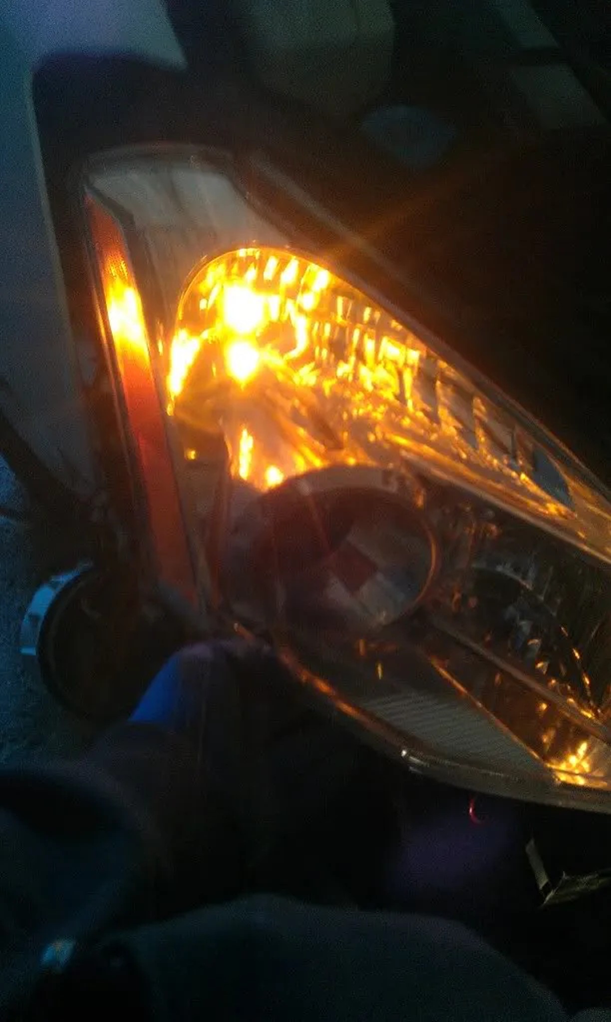
And inside the garage, with the dome lights.

035_pd.jpg

I tried taking the picture out at night, but I didn’t bring my tripod so couldn’t take the pictures with proper night camera settings. You get the idea. I’ll take some proper night pictures later when I have the time. The lights look a lot better in person.

036_pd.jpg

IMG_2933.jpg

IMG_3336.jpg

IMG00039-20110613-2226.jpg

IMG00033-20110613-2105.jpg

Thanks for watching/reading, I hope everyone enjoyed this DIY!

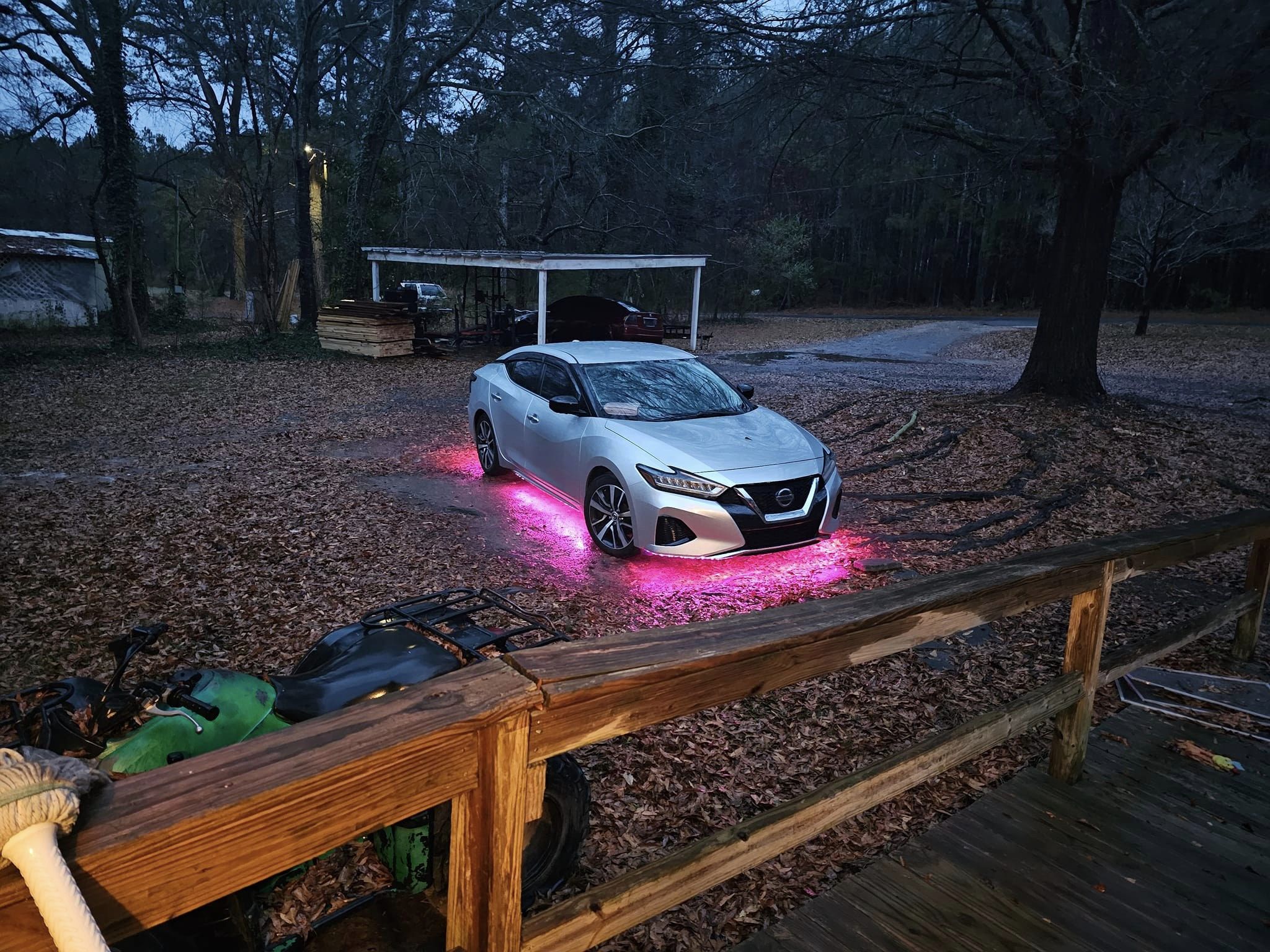
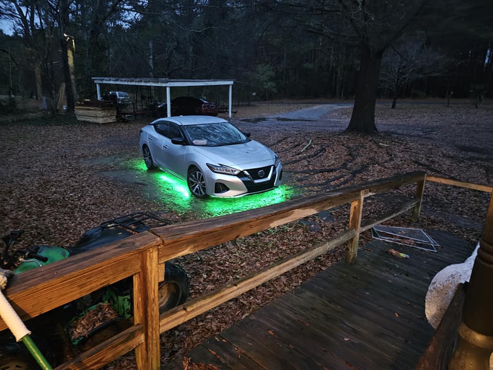
Additional Reference (Using LED Strips)

20130517_172514_zpse0f64a1c.jpg
20130518_121914_zps25056867.jpg
20130518_124425_zps4af73918.jpg
20130518_143331_zpsd6187011.jpg
20130519_171121_zpsa300d38d.jpg
20130519_171121_zpsb6693966.jpg
20130519_184607_zpsbaab3ca6.jpg
20130519_184104_zpsf18d672b.jpg
IMG_20130514_151402_zps5c0313e3.jpg
20130517_141105_zps8fa6ecf0.jpg

20130519_184607_zps5e95c067.jpg

20130518_143407_zpsfa771507.jpg

Loading

Credit: Abdala Fernandez via https://www.fastmaximas.com/2019/12/20/4th-gen-r34-quad-projector-retrofit/

I have created a video showing some of the steps I took in order to get the R34 aftermarket head lights installed on my 97 Maxima. These headlights look great however they are inexpensive aftermarket items that usually need some fine adjustments to install correctly. In this particular case they sent two left side brackets that are needed, I had to modify one of them to work on one side. Another note is that the rubber seal around the lights tend to detach easily; they can be put back with glue.

Overall I like the lights a lot, they are a great improvement to the original lights I had. These lights could be bought on eBay or on amazon here: https://amzn.to/2LPeB1t

Thank you for watching and I hope you found this to be helpful. Sign up to my email list so that you could be notified of new articles, video and product re

Loading

Credit: Mr DoLLa

So everyone doing the conversion isn’t sure why the park lights don’t work. Some suggest cutting and splicing to get them to work, but that’s not the right way. It’s as simple as removing one pin from the headlight harness and inserting it into a different location. My friend MaxPrime came through, and I showed him how simple it is (for me, anyway).

The green wire is the parking light wire, which is located in the bottom left of the connector.

Where my pick is pointing is where the green wire needs to be inserted.

Inside the connector, there’s an orange insert that keeps the pins from being pulled out. If you look at the top of the orange insert, there are two clips that need to be lifted to remove the insert. I used a fine straight pick from Craftsman.

Put the pick under the pin, push down, and pull the green wire out. You also need to remove the rubber grommet where the new pin needs to be inserted. Use the straight pick to push it out. Once you get the pin and the grommet out, insert them into the new location. It should look like this.

And this is your end result. Be sure to put the rubber grommet into the other location to prevent water from getting into the harness and causing corrosion.

Loading

Credit: Abdala Fernandez via https://www.fastmaximas.com/2019/12/20/4th-gen-r34-quad-projector-retrofit/

In this article, I go over the process for doing quad projector lights retrofit in eBay R34 Maxima headlights. Specifically the 4th generation Maxima(95-99). The projectors used were inexpensive Mini H1 projectors (https://amzn.to/2GX9GaA).

The previous lights I had on the car were FX35 projectors but the job was not great and I wanted to clean up the look of the front end of the car. I bought R34 headlights from eBay and with some modification, they fit well (I made a video and article on that here). I wanted to do an inexpensive retrofit job that was much cleaner than the previous one. I opted for Mini H1 projectors which are the common projectors that have a threaded shaft at the back and allows you to slide them through the cars existing housing light bulb socket hole.

Mini H1 Projector with shroud.

It is common to use an oven to bake the housings to then remove the lens cover. However, I used a heat gun to loosen the glue holding the covers. Being inexpensive units, it was easy to separate them; OEM lights are tougher because they are properly sealed and glued. I separated the cover from the housing and then tested the projector. I first tested it on the low beam side. I slid the projectors threads through the R34’s bulb hole and right away saw an issue. The projectors’ back shaft was not long enough to be able to catch any threads with the nut that holds the projector in place.

R34 Nissan Maxima head lights.
Lens cover separated
R34 Nissan Maxima head lights with Mini H1 projector.
R34 shroud modification
I used an angle grinder
R34 Nissan Maxima head lights modified for mini H1 projectors.
R34 shroud modification
R34 Nissan Maxima head lights modified for mini H1 projectors.
R34 shroud modification

I took out the grinder and started cutting. I used the side edge of a thick grinding wheel to remove some material from the R34’s bulb socket. I then was able to slide through the projector again and catch plenty of threads to put the nut and H1 bulb retainers. The projector looked great, it is said that the vertical alignment is not bad because it is using the stock bulbs hole which is lined up somewhat. But the rotation needs to be addressed, I eyeballed it at first to test putting the lens covers. They looked great, so next was the high beam side.

The high beam side is a different story, there are two issues to address. One, the bulb hole is too small to fit the projector back shaft through. The second is that even if you could slide the projector through, it would sit to far forward and hit the housing lens cover. In comes the angle grinder again, the goal here is to cut an oval so that the projectors reflector can sit on that oval deep into the housing and away from the lens cover; a file was used too. While cutting I would test the projector once in a while and ensure I was cutting a clean enough oval to not have gaps around the mating area to the reflector.

R34 Nissan Maxima head lights modified for mini H1 projectors.

Next was the painting, I decided to go with an all-black housing; glossy. I painted everything except the projectors shroud. First I sprayed it with a primer and then the black. Once dry I went to line up the projectors.

R34 Nissan Maxima head lights tapped for painting.
R34 Nissan Maxima light housings painted black.

To line up the projectors I mounted the housings on the car with no lens cover and used the garage wall. I know its very close but I felt it was good enough. I put in the bulbs then turned them on and rotated the projectors till I saw a horizontal line on the wall. This was not too hard because the high beam projector stays in place due to the shroud touching the floor and ceiling of the housing; holding it in place. This allowed you to rotate it to match the low beam projector. Once I had that set, I then slowly took them off so the high beam projector would not move. Then I sat it down and applied JB Weld to the back of the high beam projector. I used the original JB Weld.

R34 Nissan Maxima head lights with mini h1 projectors.
Turbo Nissan Maxima with R34 with quad projectors.

Once the JB Weld was set on both housings all there is left to do is to put the lens covers. I heated the glue areas with the heat gun all around then I placed the cover on and pressed it with my palm against the housing. I then worked on the electronics, I originally had HID ballast’s with D2S bulbs on the FX35 projectors. I wired in another set of ballasts, h1(hid) bulbs as well as relays. I turned them on and waited about 15 minutes to see how hot the wiring and the housing lens cover got. The front of the lens cover gets pretty hot, it is a focused beam like using a magnifying glass to burn with the sun. The back of the projectors got extremely hot, I was not comfortable at all with it; it felt like it could burn wiring or anything near it. So I then ordered H1 LED’s, removed the ballasts and wired the new bulbs in. The output still looks great with LED’s, you can see more intensity with the HID’s for sure but LED’s do not stay far behind so far.

I am very happy with the results and it was exactly how I pictured it. The front of the car looks aggressive and different. I will give an update with night time shots and some feedback.

Turbo Nissan Maxima with R34 with quad projectors.

Loading

Credit: Mark Baker

**THIS SETUP IS FULLY INDEPENDENT TO A SEPARATE TOGGLE SWITCH, PULLING POWER FROM YOUR AMPS POSITIVE WIRE, IT WILL NOT WORK WITH YOUR SHIFTER**

I only have an HID in the driver’s side. The passenger side is LED which has stock functionality with the shifter. I did this so I wouldn’t have to use the HID every time I back up, every time I shift into Drive causing the ballast to fire up for a split second passing reverse reducing the life span, and to be able to blind tailgaters behind me on the highway. You have no idea how many people get my attention to tell me one of my reverse lights are out. If you decide to do HIDs on both sides then just combine the positives from each ballast and ground negatives on each side near the ballast.

The “Pilot Safety” toggle switch I used had 3 wire connections. If you get a switch with only two connections, then tough titties, you figure out how that shit works, I don’t know, don’t ask me. I used regular speaker wiring (16 or 14 gauge I think, you don’t wanna use anything too small for obvious reasons) and “crimp style” connectors.

Wires will connect from:

  • SWITCH TO IN-LINE FUSE TO POWER
  • SWITCH TO GROUND
  • SWITCH TO BALLAST
  • BALLAST TO GROUND

(Switch)

Find a suitable place to mount the switch and figure out how to run wires to that location. I put mine where the heated seat switches would be if I had leather, which I don’t. Lucky me because running wires from there was extremely easy, and was an extremely convenient location to hit the switch on the go. I just ran it straight back underneath the center console, through the rear hump on the floor to under the bench seat. Then to the amp/cap and around the “carpet” lining of the trunk.

(1st wire – power input to switch)

I pulled power from my Amp/Capacitor wiring which goes directly into the switch. If you don’t have an amp, just run a wire from the battery. This is where you use appropriate sized “crimp style” connectors. You can also use a distributor block to split the amp wire so one goes to the amp and the other goes to the switch. Me being ghetto and cheap, my power wire is connected directly at the positive connection of the capacitor itself. Before I had the capacitor, I had it connected directly to the amps power/positive connection with no problems.

(^HIGHLY RECOMMENDED: Use an “in-line fuse” here BETWEEN the amp and the switch, so you don’t blow the bulb, ballast or switch, due to any spikes or whatever. I think a 10-15amp fuse will suffice but start low, fuses are cheaper to replace. I have one but I haven’t even put it in yet and haven’t encountered any problems thus far. I’m just connected directly.)

(2nd wire – Ground)

Wire comes out of the switch and is grounded to any suitable bolt. Mine is actually grounded at the amps negative terminal, don’t ask me why, it’s probably wasn’t the brightest idea, but I did. (Haven’t encountered any problems yet) Then run a ground from the negative terminal of the ballast to any suitable bolt. (Good, now your nice and grounded)

(3rd wire – Output Power wire)

Comes out of the switch goes straight to the positive connection to the HID Ballast. (Again, appropriate sized “crimp style” connectors were used here on each ends, but your set up may be different, I don’t know know. I’m not there.)
How you fit the bulb into the tail light is all up to you. I got mine from Gregory Lachhman in New York who did his a long time ago. He got an extra Oem bulb socket from the the JY or whatever, drilled a big enough hole through it to fit the bulb, and sealed it in place with JB weld I think. He helped me through this when I did it so credit goes out to him. So my HID bulb is pretty much plug and play. Perfect fit. Although if the bulb blows out, I’m gonna have to find another socket to drill a hole in and fit the bulb.

I used a slim ballast and just used double sticky tape to mount it to the inner fender wall.
My bulb is 6000k.

I’m sure there are many other methods to doing this, but this is how I did it. If this DIY has helped you, please post a pic of your setup and tag me in it. Thanks.

Car Pics:

Loading

Community Member Credit: Kevin Kryzda

Tools necessary:

  • 10mm socket and an extension
  • Flathead screwdriver (or pry tool)
  • Wire/Side Cutters or Wire Strippers
  • Wire taps or soldering tools
Before You Start:
The purpose of this modification is to re-wire your fog light relay under your hood to receive signal from an accessory source of power that is independent of anything else in the car, allowing you to turn on your fog lights without the headlights as well as run them with your high beams. The modification is very inexpensive and will avoid/end the problems with the “windshield wiper” write-up.
Steps:

1. First off your going to want to locate the relay box located on the left side of your under hood as indicated by the arrow.
2. Then you will want to remove the reservoir in between you and the relay panel. This is attached by two 10mm bolts on the left side of the car. Following this, set the reservoir aside.

3. Next you will want to remove the cover from the relay box prying the two tabs holding it on outward and lift the cover up.

4. Now you will want to remove the air conditioning relay and the heated mirror relay if you are equipped with them. To do this, use your pry tool and insert on the side of the relay that has a clip, push away from the relay and then pull up on the relay itself.

5. Next remove the two exposed 10mm bolts holding the relay box in. Now pull up on the box and release the snap tab located on the bottom arm of the box.
6. Once the relay panel is free from the car you will need to open it to expose the wiring inside. To do this release the 3 clips on the right and left side of the box indicated with the arrows. Then open.

7. Now that you have the wiring exposed you are going to be working with the signal wire from the fog relay and the accessory power wire from the air conditioning relay. The yellow wire coming out of the fog relay is the wire you want to give +12V and the pink wire with a blue stripe from the A/C relay is where you will get it. To access the pink wire better you will probably need to remove the relay harness from the housing. To do this pry in the direction indicated and push out the bottom of the housing.

8. Now cut the yellow wire and without cutting the pink wire run a wire from it to the yellow wire leading into the blue relay harness.

9. I prefer soldering all of my connections but you can attach how you like. I highly recommend no matter what you do though, make sure to tape up everywhere you work. Make sure to tape up the open end of the yellow wire as well.

10. Now close everything up and reverse the previous steps to return everything how you found it. Flip your fog lights on and admire. You can turn them on whenever you want granted the car is on.

Loading