Credit: Harold Smith


![]()


")

Community Member Credit: fxlr8
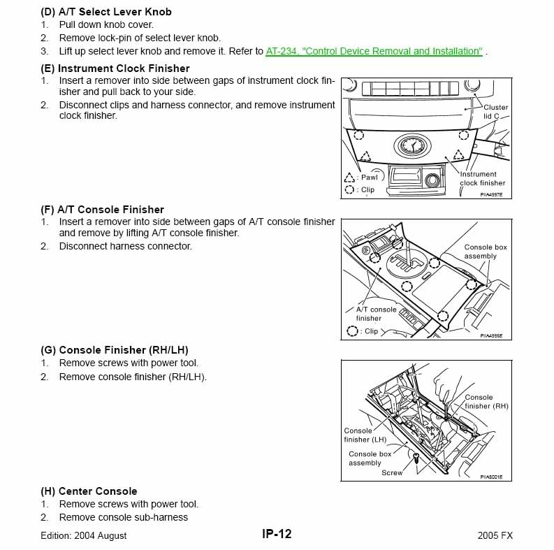
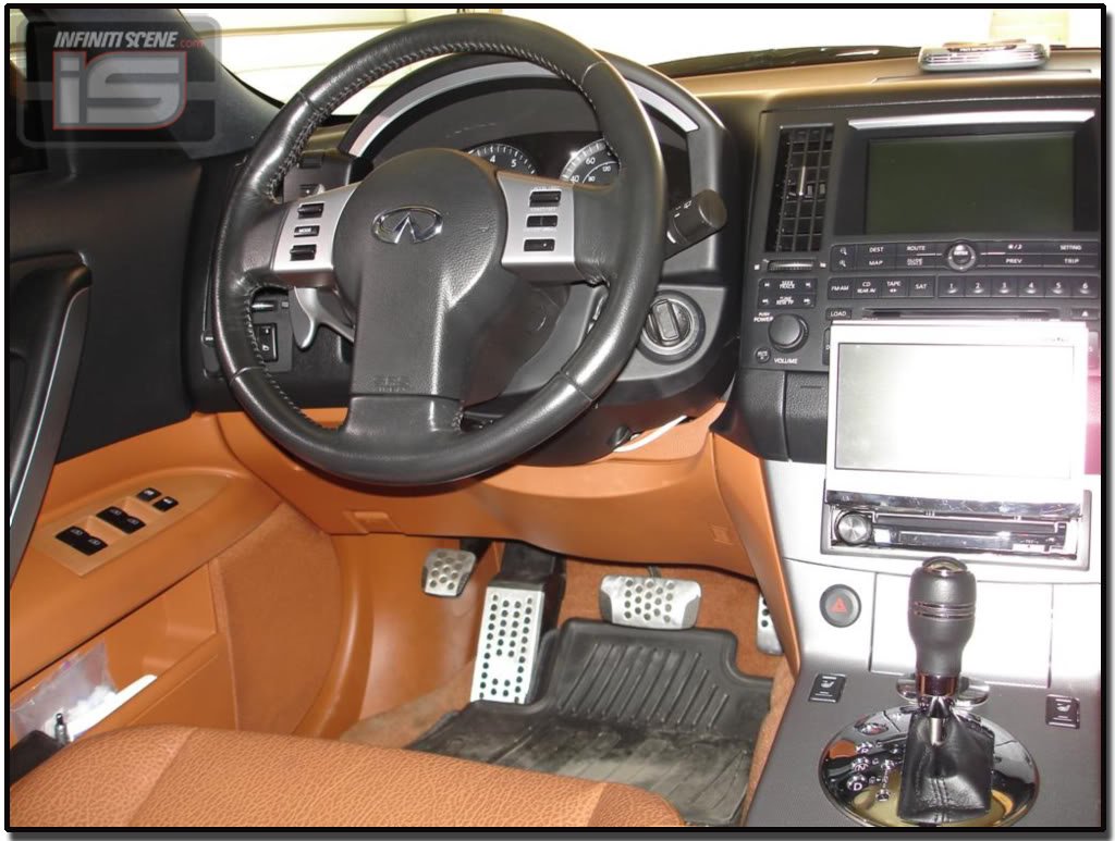
1. Remove center console following instructions:
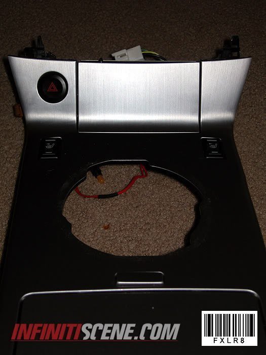
2. Remove old shifter panel top and bottom by unscrewing the screws on the underside of the old panel.
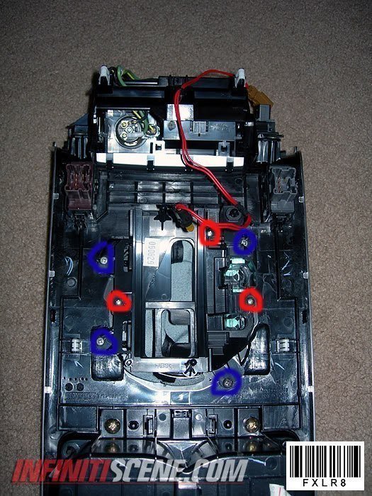
3. Put the new 2006 shifter panel and bottom boot together in the hole and screw the two pieces together with the 3 screws in red.
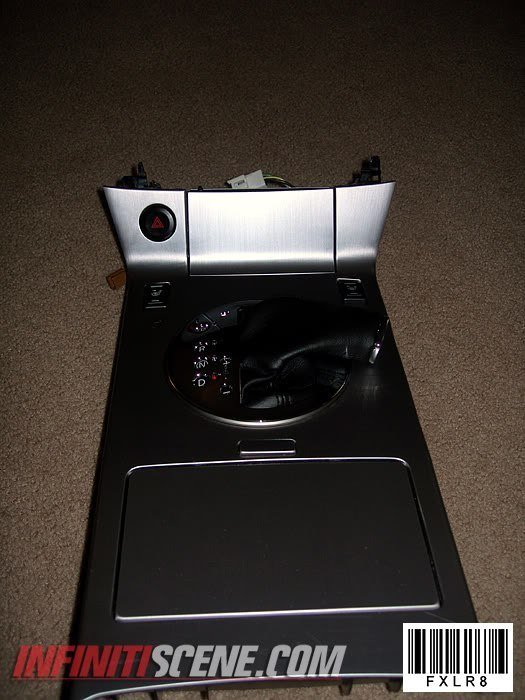
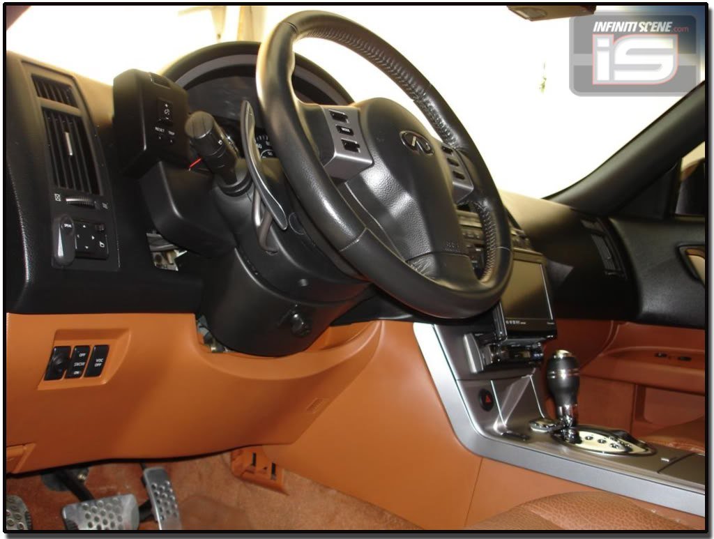
4. Now you are going to align the new shifter, on the two I did I pushed them all the way forward towards the front of the car and then centered it left and right.
Align the panel in a way where you can shift through all gears smoothly…..and then do the next step.
5. You then are going to figure a way to keep it from sliding around while you shift. I used 4 screws on each of the tabs shown in blue…you can use double-sided tape but I am not sure how well that will work while trying to align the piece.
REMEMBER: Do not screw the screw all the way in or you might go through the metal on the other side.
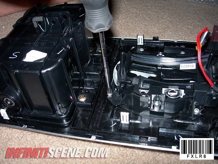
(MAKE SURE YOU ATTACH THE LIGHT UNDER THE SHIFT PANEL)
6. Put the completed panel and console back on the car, what I did was reattached all the wires…. make sure all items on the console work (lights, hazard signal, seat warmers, etc.). I then put the shifter in neutral and then slid the console on the shifter making sure I go through the shift indicator slider on the shifter panel.
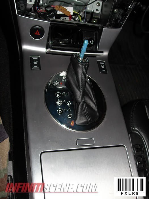
7. Put your shift knob back on and make sure you can shift through all gears… after that put all your console pieces back together and your done!!
![]()

Community Member Credit: IvoRoyfx35Member
Product: JDM VIP style Puddle Light Kit
Cost: $100 including shipping to US address
Tools Needed: Power drill, drill bit, hole-saw, screwdrivers.
Optional: A few fancy tools (see below), relay switch, wire terminal, splice wire connector, extra wires.
Installation time: 4 hours when sipping some beer and enjoying the installation. Probably can be done in 2 hours for you hard-core DIY people.
Warning: Always use caution as you are working with electrical wires. When connecting to the car’s electric wires, disconnect the battery to ensure your safety.
Introduction
So, I’ve seen these puddle lights in person on a Z & Lexus IS and they looked really good. The only concern I had on buying this for my FX was how it was going to look on a car that wasn’t slammed, let alone not even dropped. After many weeks of debate, I finally decided to just take the plunge and go for it. After many hours of research, I decided to go with JDM puddle lights from Elite Auto Style (I have no affiliation with this company). Several things set these apart from the other puddle lights that I’ve run across. These were pre-assembled for easy mounting. The LEDs are made of high quality (based on the reviews I’ve read). The last thing I want is for one of the LEDs to burn out or change color, etc. That would be a major PIA, especially with a flush installation that I was going to do. The lights are focused and do not spread out like some of the other brands. And lastly, it arrives from Japan at my doorsteps in 3-4 days from the date of the payment. How can you go wrong with that?
Anyway, so here’s a DIY on the installation process, and I took lots and lots of pics and tried to be very thorough. Hope you enjoy it as I’ve had a lot of fun doing it and wanted to share it with everyone.
Instructions
1. So I got the package and this is how the puddle lights came in the box. Nice chrome plates and the led bulbs had a thick coating of some sort, I guess for extra protection against rocks and all that good stuff on the road.

2. Back of the puddle lights…This is what I mean by pre-assembled. Some of the other lights I’ve seen online didn’t have these housings with screw nut for an easy flush install. Some just comes with 3M mounting tapes (Ewww). Now back to the ones I got, you can choose to use the mounting brackets that come in the box. I wanted a flush install because I don’t want anything sticking out of the side skirts as well as exposed wires.

3. Side Skirt Removal – Remove the screw located at the rear of the side skirt. I used this fancy tool that my friend had, but if you don’t have it you’ll need to remove the rear wheels because the space is too tight to work with a screw driver.

4. Remove these 5 screws located underneath the side skirt.

5. Remove this screw connecting the side skirt to the front mud flap.

6. Remove the three screws behind the front mud flap and the mud flap should just fall off of the car.

7. Pry apart the side skirt using a flat screw driver (cover with towel if you want, I didn’t and it was fine). I found that starting from the back of the side skirt (near the rear tires) was the easiest in taking these off. You’ll need to apply firm but gentle pressure. Once you pop the first two clips off, the rest will pop out pretty easily.

8. Here is the clip ‘housing’ that is on the car.

9. Here is the clip ‘insert” that is on the side skirt. Sometimes, it helps to use a thin screw driver to push down on this clip insert so you won’t break the clip housing when prying it apart.

10. I still managed to break a small part of two clip housings (red arrow)…But the skirt went back on fine and there was 0 rattle so don’t worry yourself too much if you break these.

11. Now comes the fun part for all you math wizards. Mark the side skirt so that each light has equal distance from each other and from the front and rear ends of the side skirt. You can measure the length of the side skirt and do some crazy math formula and figure it out yourself. For me, I just made sure that the distances between the lights were equal and the distance from the edge of the skirt was equal. Make sure that you are marking on a place that will be parallel to the ground once the skirt is back on the car (so the light reflected on the ground maintains the circular shape) and also make sure that your marks are in A STRAIGHT LINE!!! If not, they will look staggered on the ground.

12. Once you’ve made all five marks, drill a small pilot hole.

13. Select the right size hole-saw and drill through the pilot hole from the OUTSIDE. I think I used a 3/4″ hole-saw, but make sure you measure your light base and drill appropriately. You only get one chance. (The hole can be slightly bigger than the base since there are tightening nuts for these lights.)

14. VERY IMPORTANT – Before doing anything else, grab yourself a cold one and pat yourself on the back for having gone this far without breaking anything.

15. Insert the puddle lights through the hole and tighten with the provided nut.

16. Connect the red wires together and do the same for the black wires.

17. Your packet should have 2 of the 10 lights that have only 1 red / 1 black wire connectors. These will go to the end of the side skirt. If you only have 1 or none with single connectors, (I only had 1) don’t panic! You can just tape off the ends with electric tape and you’ll be good to go.

18. All lights are now connected and exposed metal connectors covered with the rubber transparent cover. This is important as you don’t want any part of the red connector touching the black connector when the lights are on.

19. Put the skirt back on with the red/black wire ends out. Remove the side kick panel.

20. Remove the door step and say hi to the dried out bug that somehow managed to get in there.

21. As with the side skirts, gentle but firm pressure should pop the door step out without breaking the clips.

22. Now, before screwing the skirt back on, test out the lights. I used the battery of my drill to temporarily power the lights. Then, remove the remaining plastic parts near the side kick panel and lift up this black rubber/foam liner so you can put the wires through them and continue the CLEAN installation.

Follow the above steps for the other side.
23. Use the provided extra wires to connect the left side of puddle lights to the right side of puddle lights.

24. I used a flashlight to figure out where I can make the connection (underneath the dash).

25. A-ha!

26. I used another one of my friend’s fancy tools to carry the wire through this opening. But a coat hanger will do the trick just as well.

27. Connect the wires and tuck them in under the carpet.

28. Back on the driver’s side, cut the extra wires off and join the red to red & black to black. You can try to tap the conjoined black wire to the ground wire in the fuse box, but I just decided to ground the wire to the metal frame of the car (wire terminal sold at radioshack).

29. Now this is where you can go off on your own. You can certainly use the provided switch to create a switch that you can use to turn on/off the puddle lights, or tap into any 12v source such as side kick door lights, parking lights, etc. As for me, I wanted to tap into the doom lights. Then, the puddle lights will come on when I press unlock and go off when I press lock with the remote. It will also go on when the doors are open and go off a few seconds after the door is closed, as with the doom lights.
In order to do this, create a relay switch (radioshack) similar to the one shown here. I don’t know too much about wiring so my friend did this part for me, but it seems pretty simple. Put the red wire into the relay switch, make a loop with the white wire, and take the other white wire to the fuse box. Also take the blue wire to the fuse box to tap into the dome light wire.

30. Tap the white wire to the red wire shown.

31. Tap the blue wire to the purple/white wire shown. The purple/white wire is the dome light.

32. Make sure no wires are exposed and the newly created connections properly taped off with electrical tape / zip tie. Put everything back on.

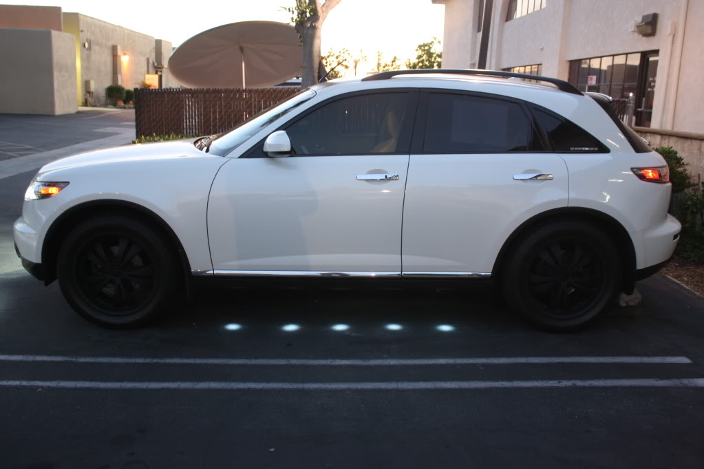
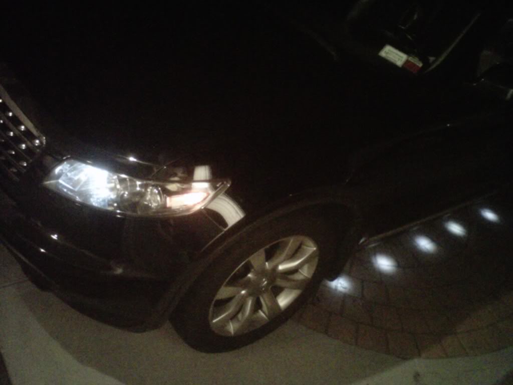
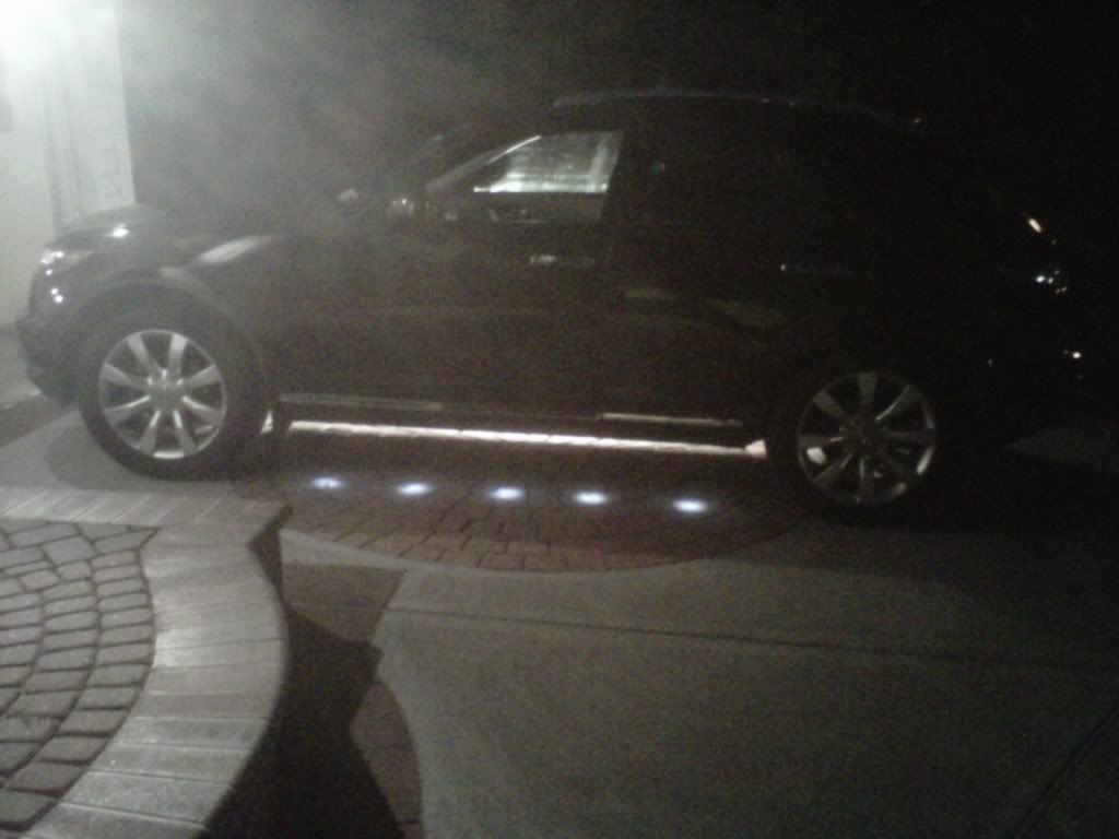
This is how each puddle light looks with the flush install.


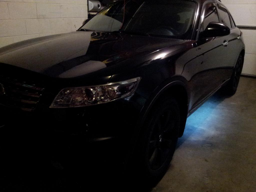
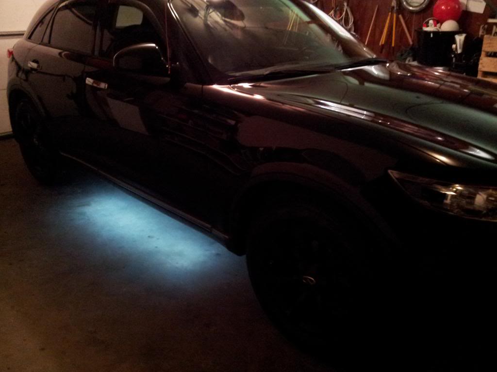
And inside the garage, with the dome lights.

I tried taking the picture out at night, but I didn’t bring my tripod so couldn’t take the pictures with proper night camera settings. You get the idea. I’ll take some proper night pictures later when I have the time. The lights look a lot better in person.

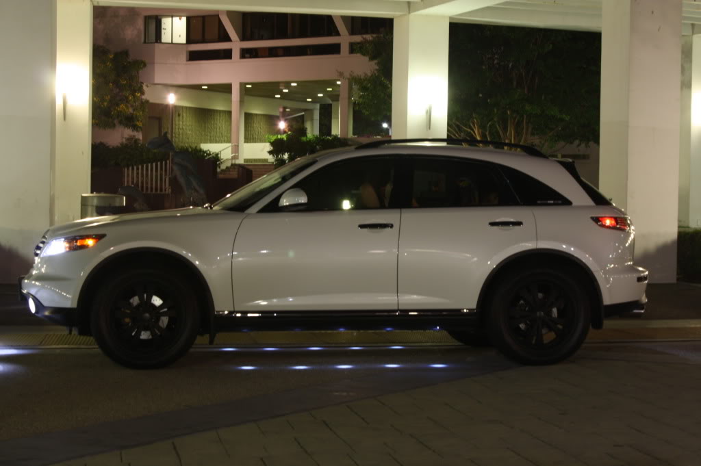
Thanks for watching/reading, I hope everyone enjoyed this DIY!


![]()

Order Link: https://www.etsy.com/listing/1425045241
Description: KMH to MPH Conversion Decal | 2 Styles + Multiple Colors | Free shipping
Seller: OWLJDM
Price: $3.49 each


![]()
")

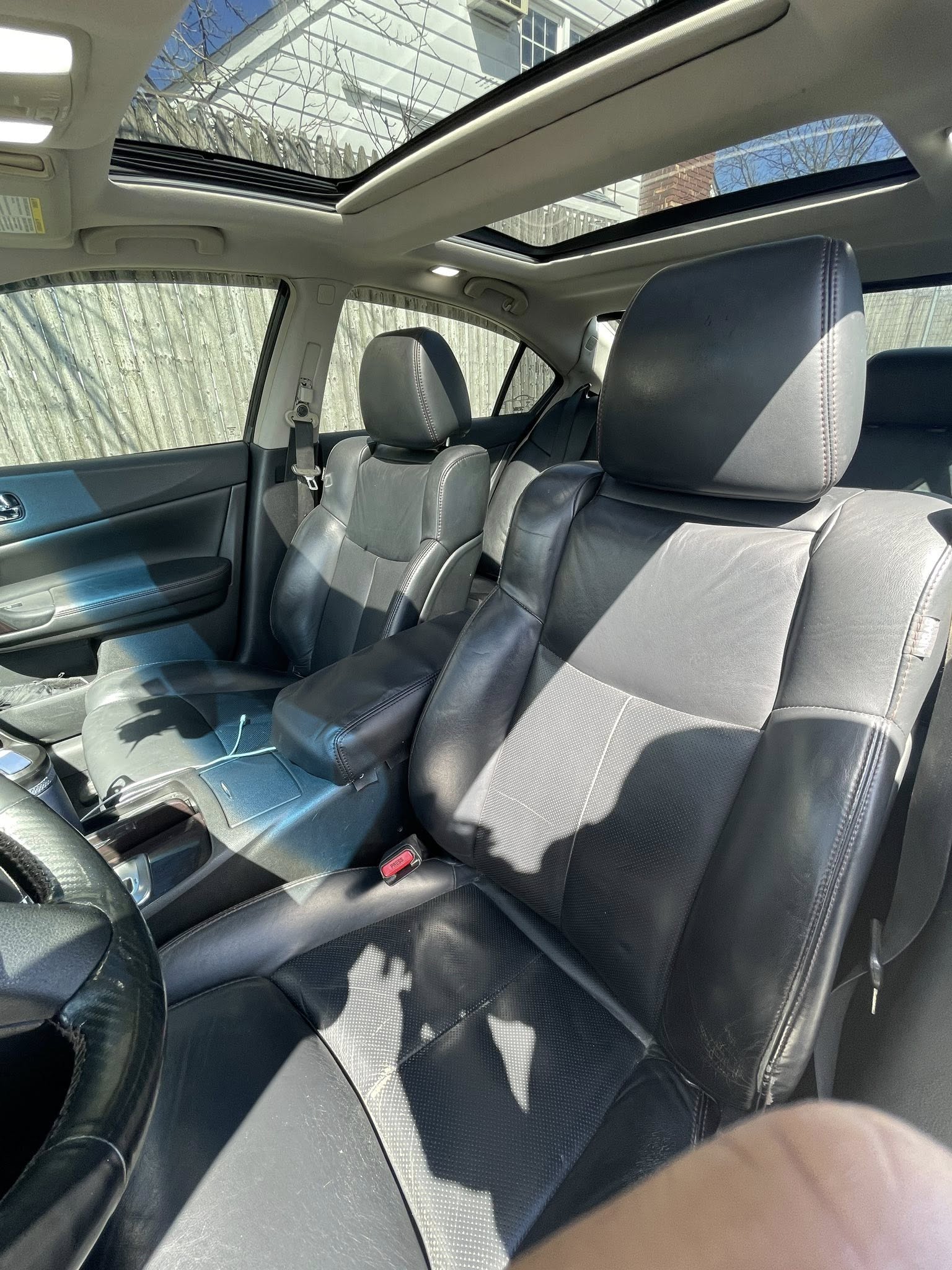
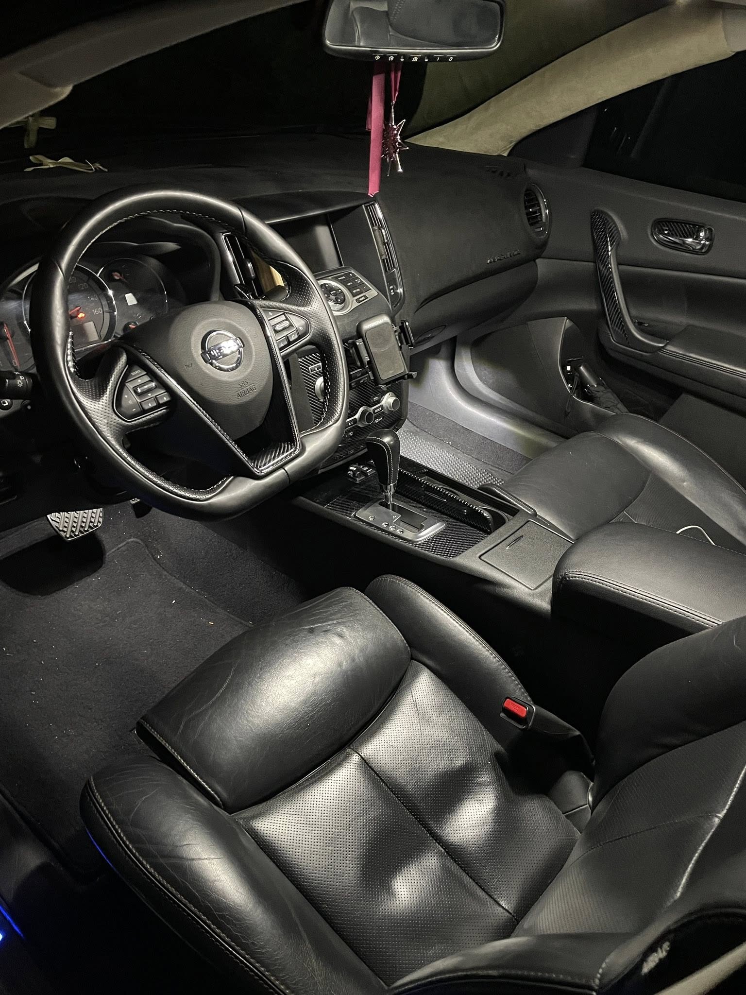
Credit: Kevon M. aka nebula.maxima
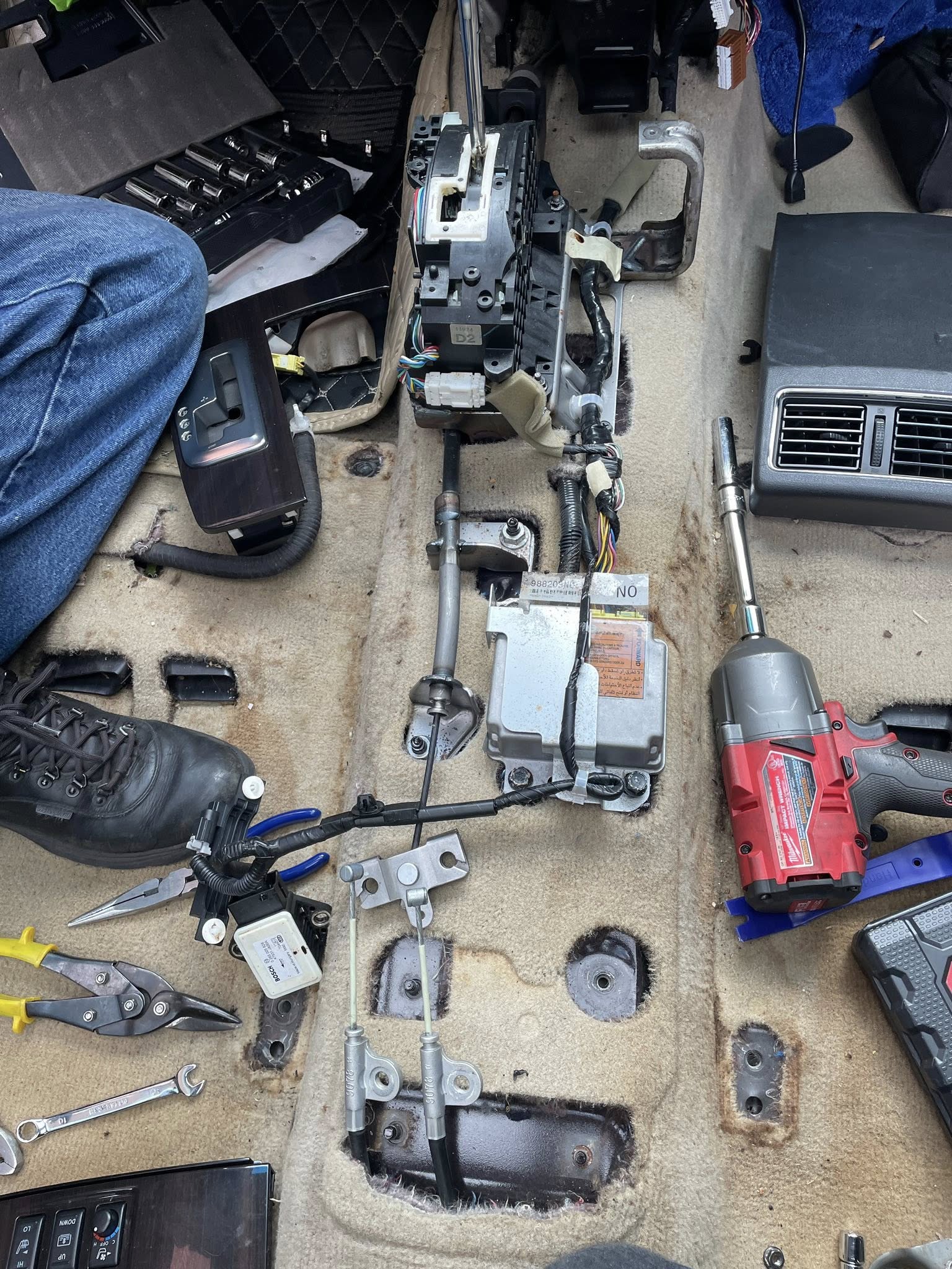
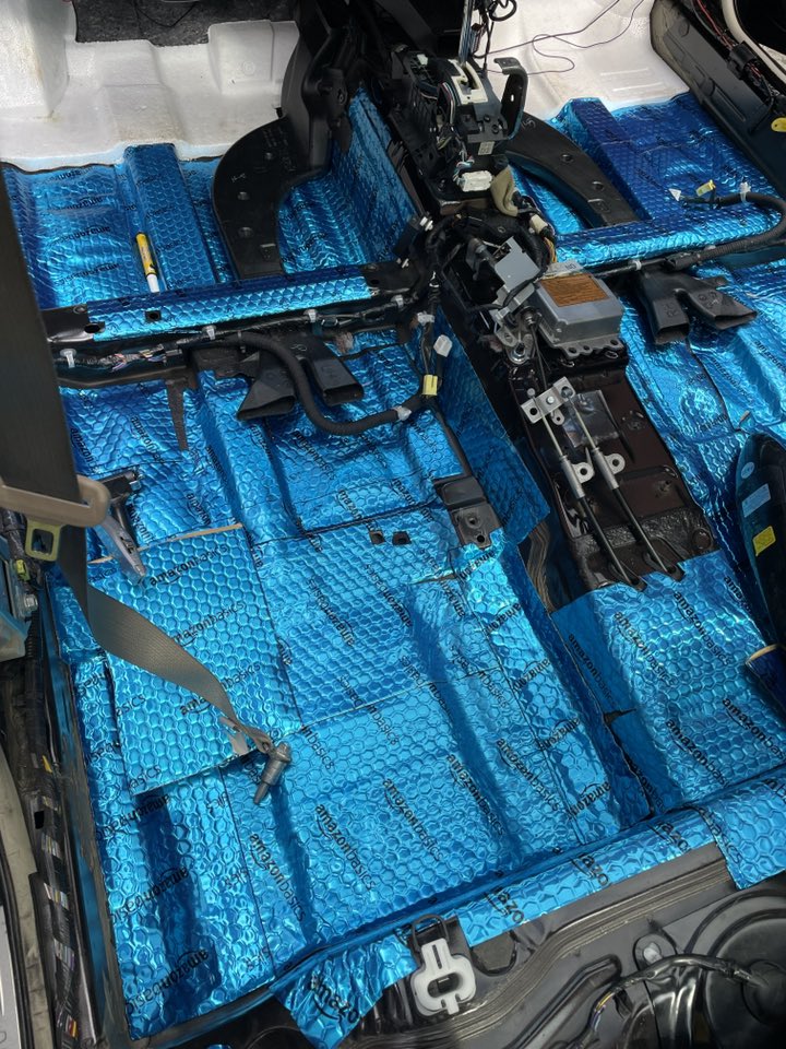
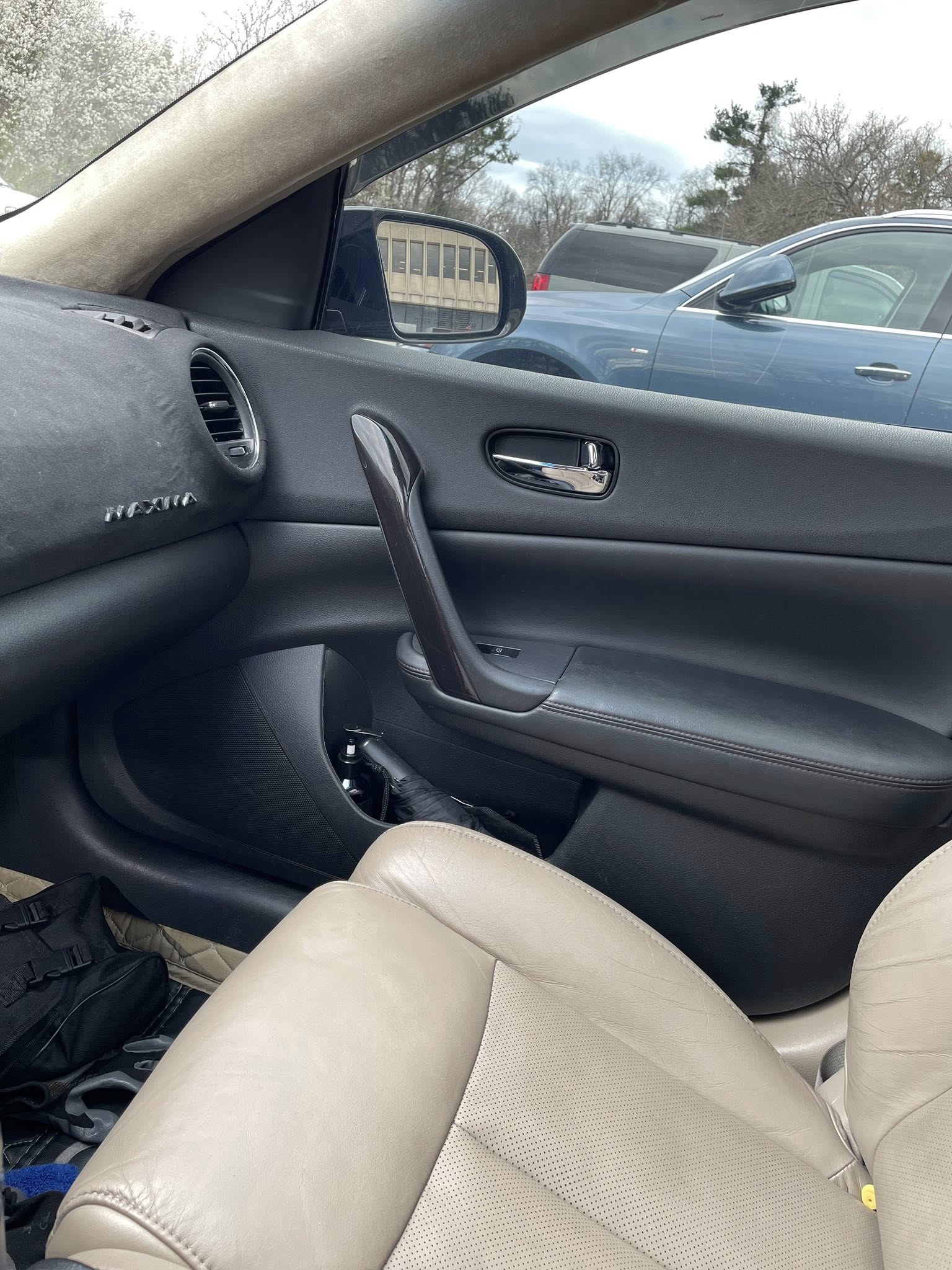
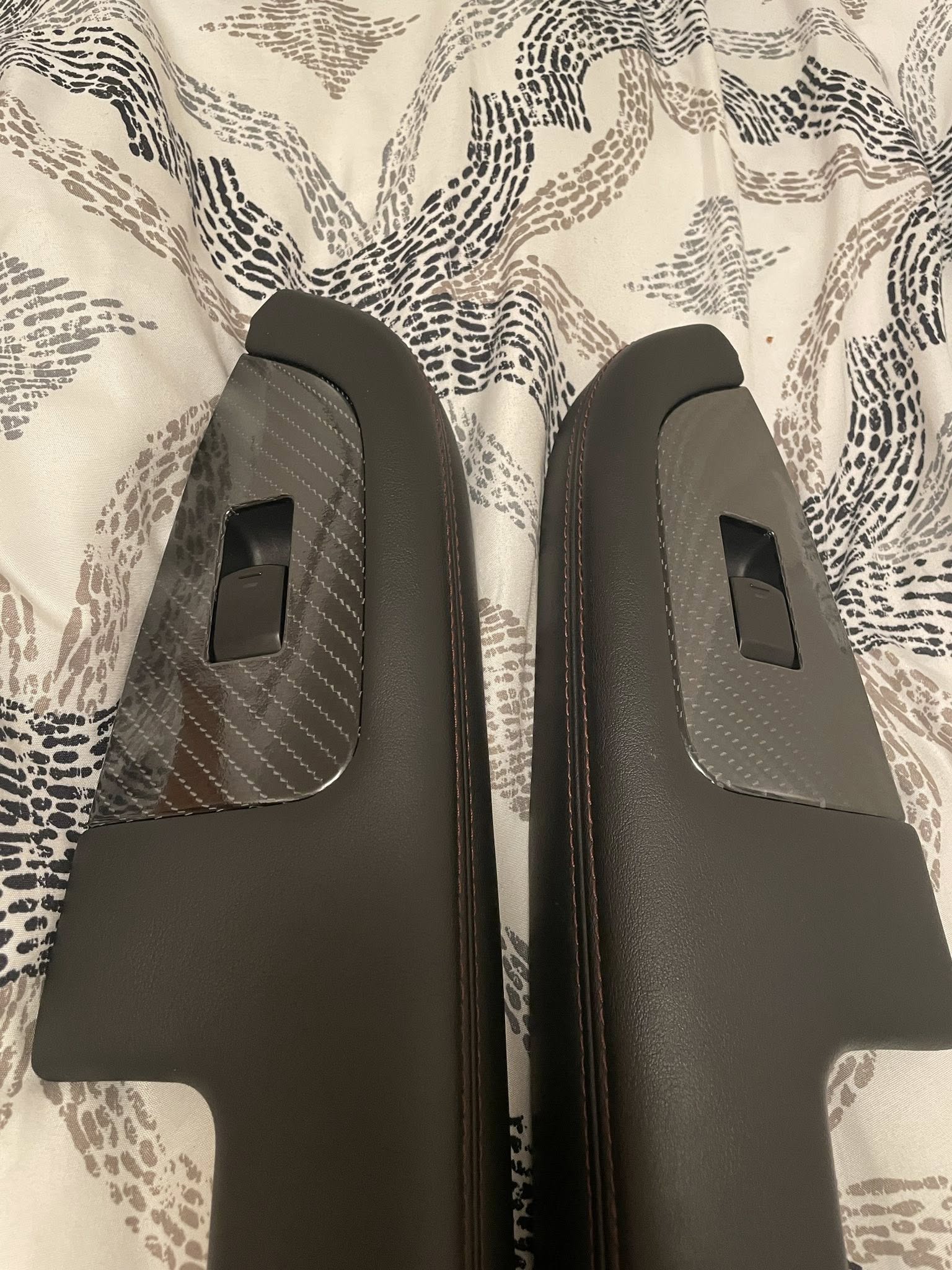
Finally re-upped the whole interior from tan to black. Sourced every piece I needed—seats, door panels, floor panels, rear deck, glove box, dash panel, and fresh carpet—and gutted the cabin. While the carpet was out, I laid down sound deadening on the floors to cut down on road noise and add a bit of refinement. Wrapped the old woodgrain trim in carbon fiber vinyl for a modern touch.
The hardest part was tracking down the right front seats with both AC and heat at a decent price, but after some hunting, I got it done. The transformation is night and day—feels like a completely different car now.

![]()
")
Credit: Kevon M. aka nebula.maxima
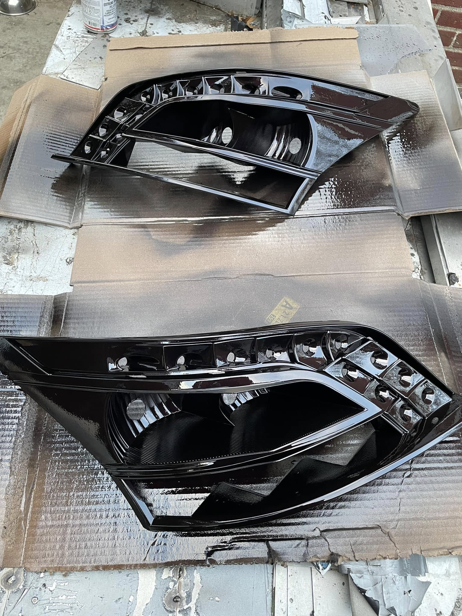
I put together a 3-part video series on how to make clear tails:
Super detailed from start to finish—perfect if you’ve been thinking about trying it yourself.
![]()

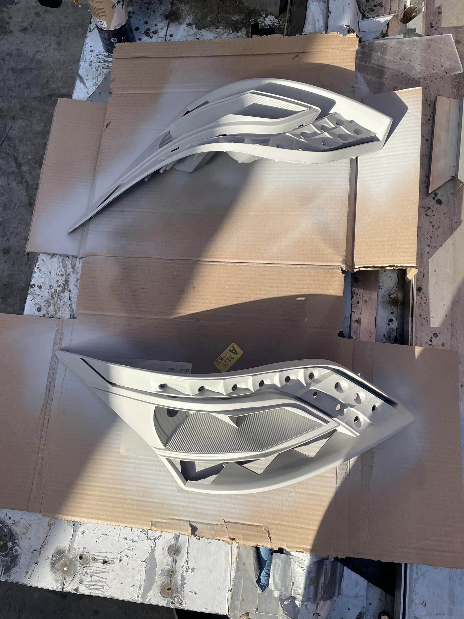
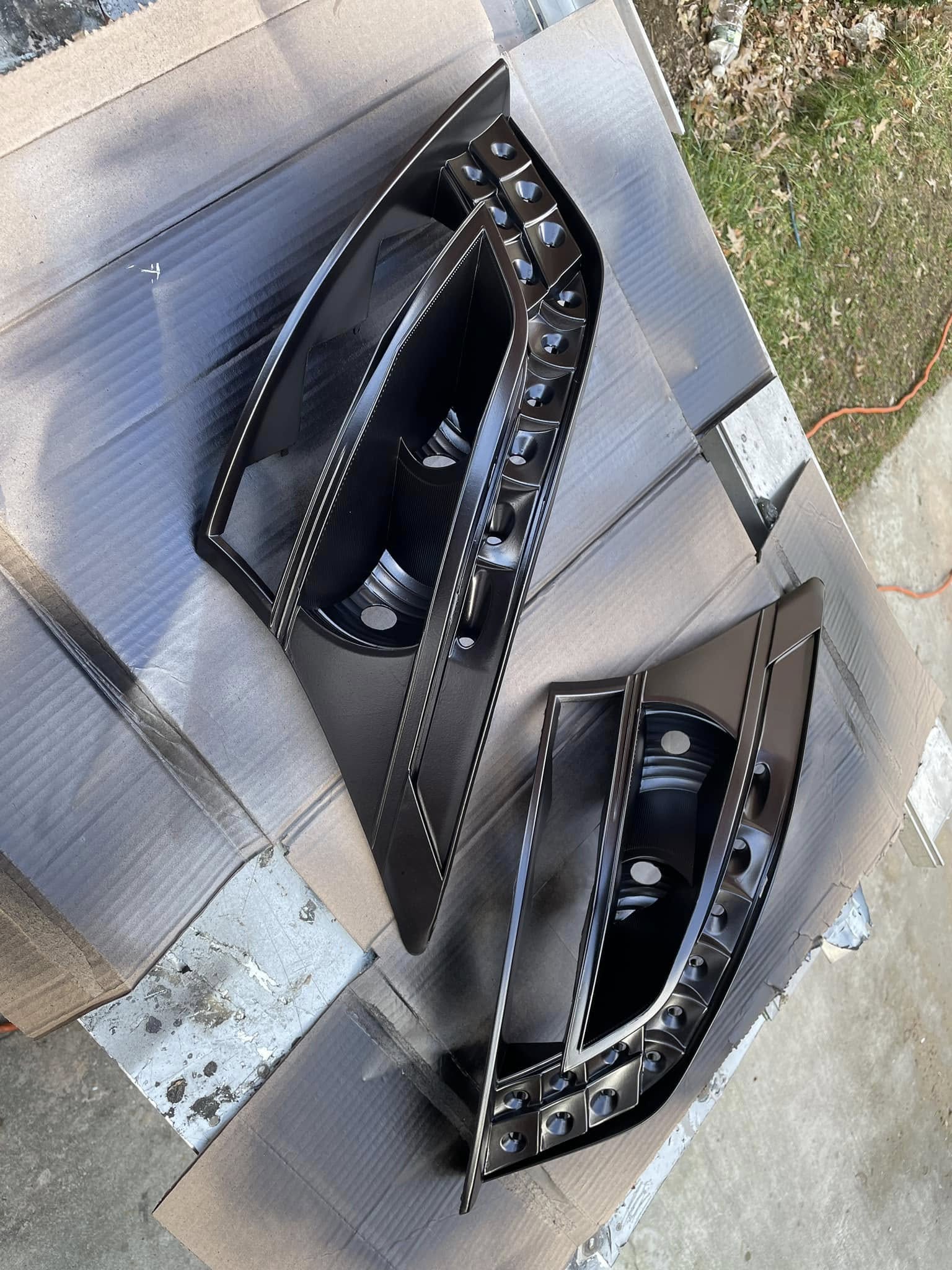
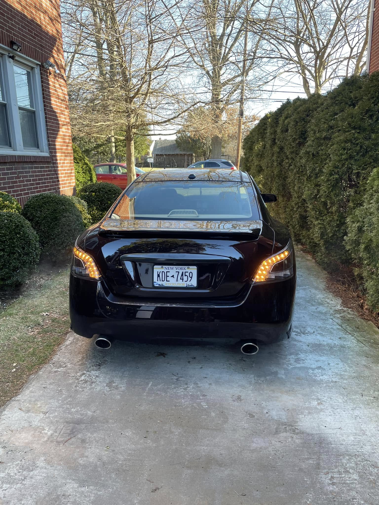
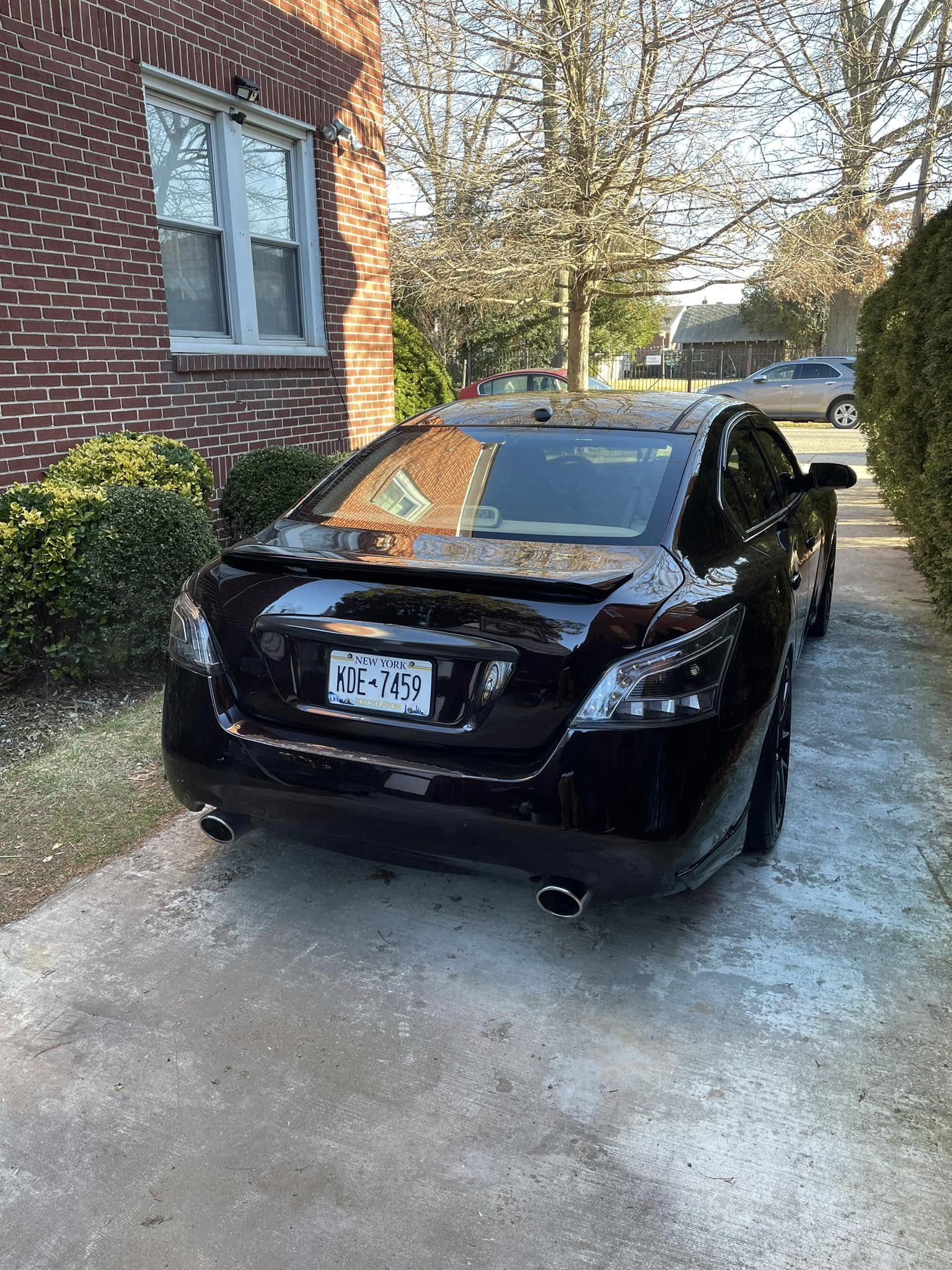
Credit: Kevon M. aka nebula.maxima
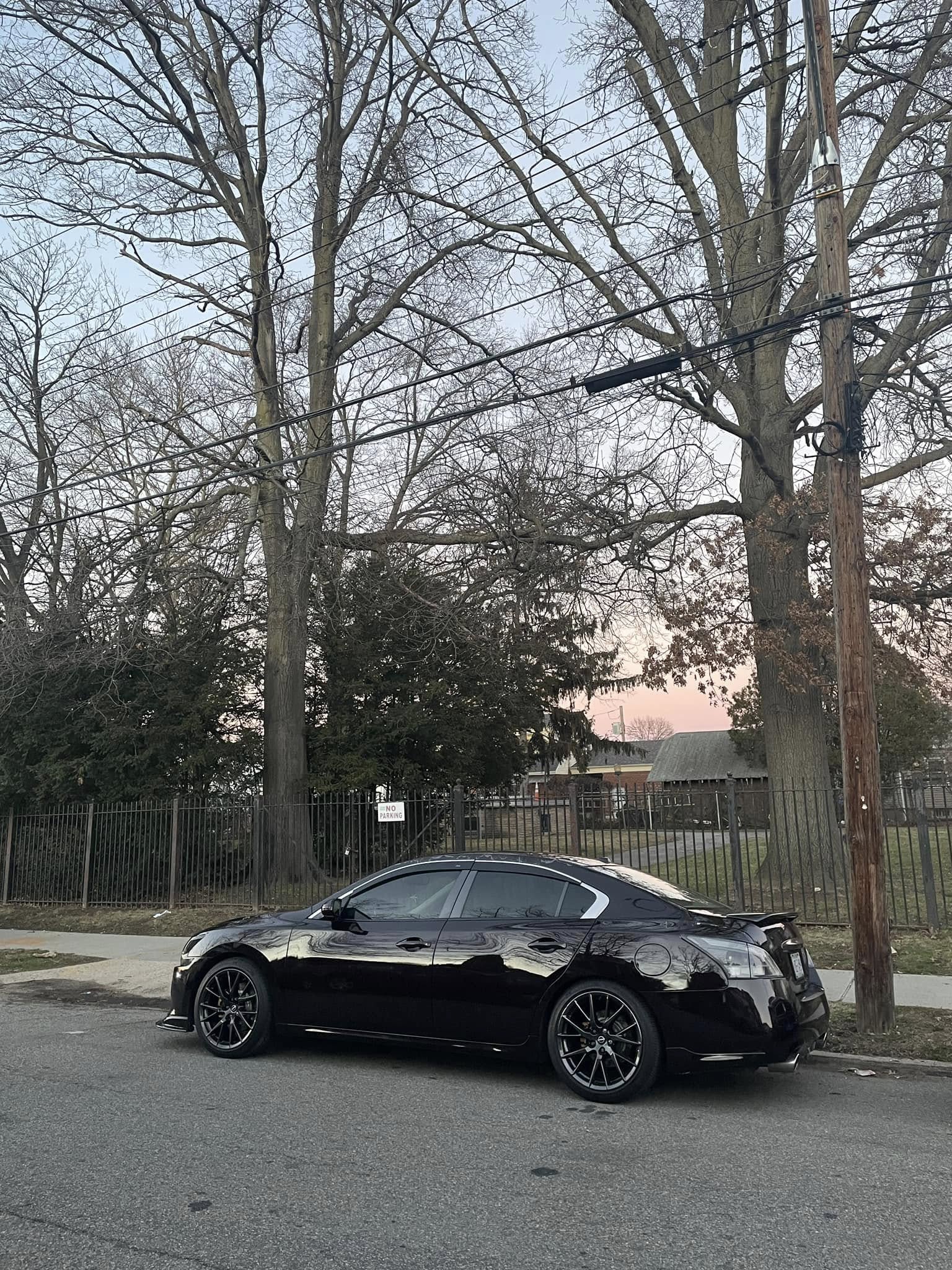
Took on a new project I’m calling transparent tails. Chrome was color-matched to crimson black for a sleek, factory-plus look.
Setup includes:
![]()

Credit: Kevon M. aka nebula.maxima
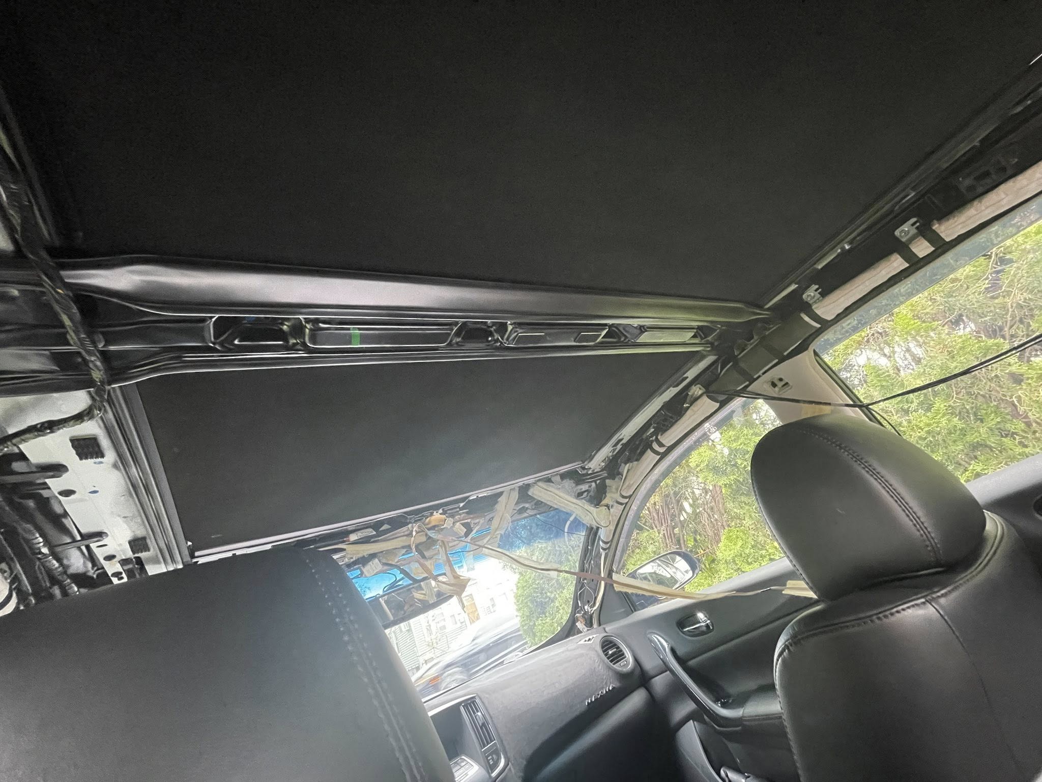
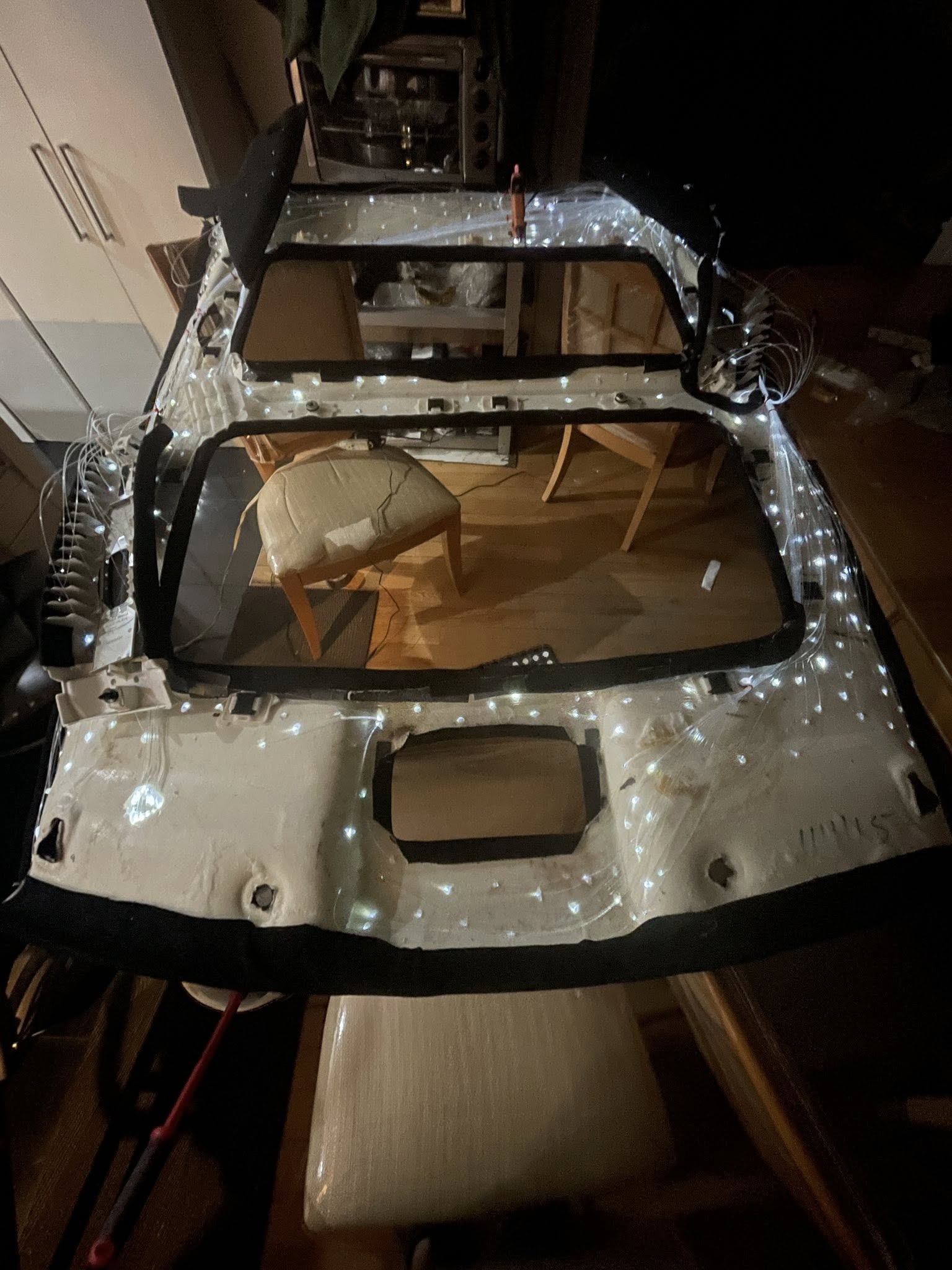
Wrapped the headliner and installed a full starlight setup—easily the most tedious mod I’ve ever tackled. Added stars in the B & C pillars, plus meteor streaks flowing down the A pillars for extra effect.
All the tan trim and sun visors got repainted in black using plastic/vinyl paint, then sealed with a matte clear coat for that OEM look. I even painted the pano roof shade black—had to do it inside the car since pulling it out would’ve risked messing with the motor. It’s a bit stiffer now rolling in and out, but still works fine.
One thing I skipped was removing the old headliner fabric before wrapping in suede—definitely caused some adhesion issues. Looks like I’ll need to redo it at some point, but for now, the transformation is on another level.
![]()
 Fuses and Relays Diagrams")

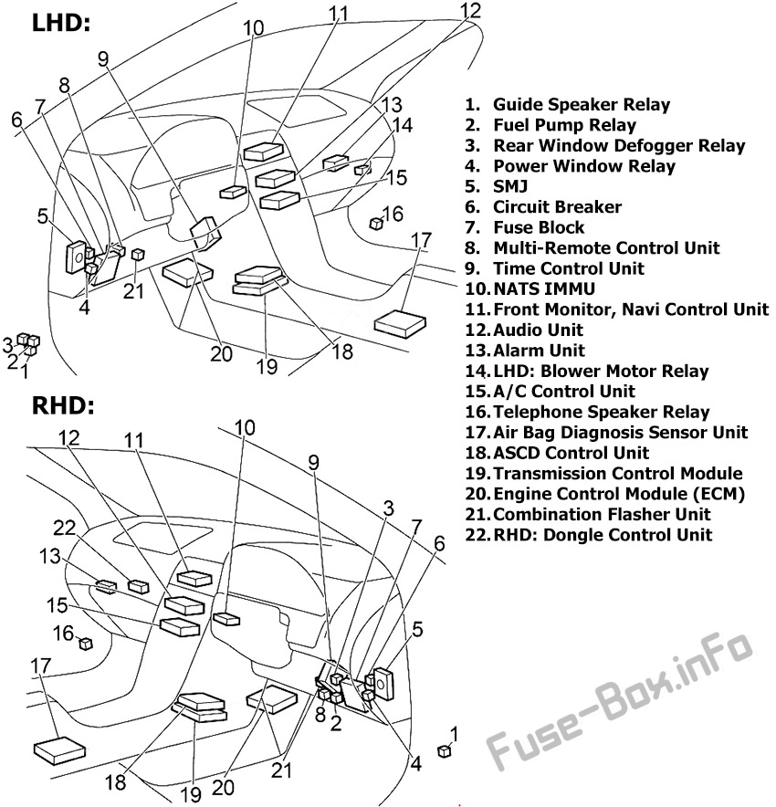
The fuse box is located behind the cover on the driver’s side of the instrument panel.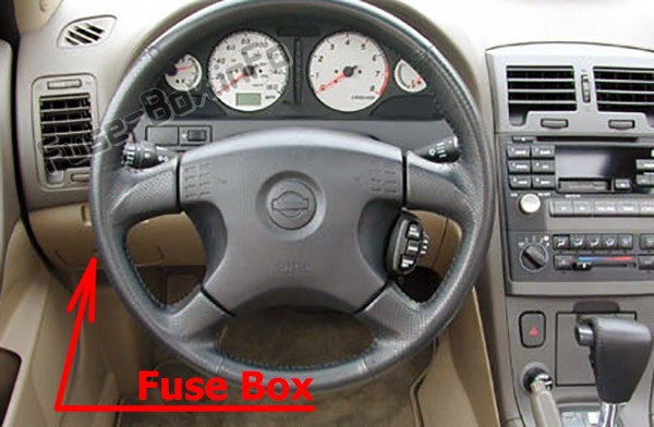
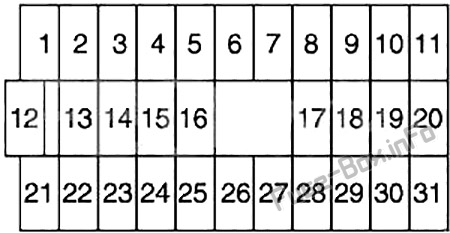
Assignment of fuses in the instrument panel
| № | Amp Rating | Description |
|---|---|---|
| 1 | 10 | Steering Wheel Receiver Control Switch, Audio Unit, CD Player, CD Changer, Woofer, Telephone Speaker Relay, Antenna, Telephone Control Unit, Front Monitor |
| 2 | 15 | Stop Lamp Switch (Rear Combination Lamp LH/RH, High-Mounted Stop Lamp), ASCD Control Unit, ABS, Transmission Control Unit |
| 3 | 15 | Trunk Lid Opener, Fuel Lid Opener, Trunk Lid Opener Relay (RHD) |
| 4 | – | Not Used |
| 5 | 15 | Hazard Switch (Combination Flasher Unit), Multi-Remote Control Unit |
| 6 | 15 | Front Fog Lamp Relay |
| 7 | 20 | Rear Window Defogger Relay |
| 8 | 15 | Heated Oxygen Sensor |
| 9 | 10 | Heated Seat Switch LH/RH |
| 10 | 10 | Daytime Light Control Unit, Headlamp Aiming Control Unit, Door Switch, Headlamp Washer Control Unit, Height Sensor Rear LH/RH, Clearance Lamp LH/RH, License Lamp LH/RH, Rear Combination Lamp LH/RH, Power Window Switch (Illumination), Power Window Relay, Time Control Unit, Rear Window Defogger Relay, Auto Anti-Dazzling Inside Mirror, ASCD Brake Switch, ASCD Clutch Switch, ASCD Control Unit, Park/Neutral Position Relay, Data Link Connector, Multi-Remote Control Unit, Alarm Unit, Navi |
| 11 | 10 | Transmission Control Unit, Revolution Sensor, A/T Mode Switch |
| 12 | 10 | Key Switch, Time Control Unit, Combination Meter, Clock, Alarm Unit, Security Indicator, NATS Immu, Navi, Data Link Connector, A/C Auto Amplifier, Transmission Control Unit |
| 13 | 10 | Interior Lamp, Front Step Lamp, Door Switch, Time Control Unit, Ignition Key Hole Illumination, Spot Lamp, Vanity Mirror Lamp LH/RH (Illumination), Trunk Room Lamp/Switch, Rear Window Defogger Relay (Door Mirror) |
| 14 | 10 | Combination Meter, Clock, Door Mirror Remote Control Switch, Navi Control Unit, Front Monitor |
| 15 | – | Not Used |
| 16 | 15 | Power Socket |
| 17 | 10 | Injector, Fuel Pump Relay (ECM) |
| 18 | 10 | Air Bag Diagnosis Sensor Unit |
| 19 | 10 | A/C Auto Amplifier, A/C Relay, A/C Control Unit, Air Mix Door Motor |
| 20 | 15 | Park/Neutral Position Relay (Park/Neutral Position Switch), NATS IMMU, EVAP Canister Purge Valve Volume Control Solenoid Valve, Swirl Control Valve Control Solenoid Valve, Cooling Fan Relay (1, 2, 3), Variable Induction Air Control System, ASCD |
| 21 | 10 | Daytime Light Control Unit, Engine Control Module |
| 22 | 15 | Cigarette Lighter |
| 23 | – | Not Used |
| 24 | – | Not Used |
| 25 | 20 | Front Wiper Motor, Front Washer Motor, Front Wiper Switch |
| 26 | 10 | Hazard Switch (Combination Flasher Unit) |
| 27 | – | Not Used |
| 28 | – | Not Used |
| 29 | 15 | Fuel Pump Relay (Fuel Pump and Fuel Level Sensor, Condenser) |
| 30 | 10 | Combination Meter, Daytime Light Control Unit, Alternator, Park/Neutral Position Switch (Back-Up Lamp), Door Switch, ASCD Brake Switch, ASCD Clutch Switch, ASCD Control Unit, Park/Neutral Position Relay |
| 31 | 10 | ABS |
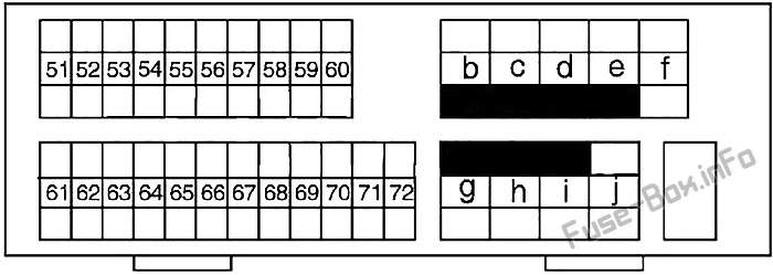
Assignment of fuses in the engine compartment
| № | Amp Rating | Description |
|---|---|---|
| 51 | 15 | Blower Motor Relay |
| 52 | 15 | Blower Motor Relay |
| 53 | – | Not Used |
| 54 | 20 | Headlamp (Left) Relay, Headlamp (Left Low Beam), Diode |
| 55 | 20 | Headlamp (Right) Relay, Headlamp (Right Low Beam), Diode |
| 56 | 15 | Audio Unit, CD Player, CD Changer, Telephone Control Unit, Navi Control Unit, Front Monitor |
| 57 | 10 | Horn Relay |
| 58 | 15 | IACV-ACC Valve, ECM Relay (Condenser, Ignition Coil) |
| 59 | 15 | ECM Relay, NATS IMMU, Throtlle Position Switch, Crankshaft Position Sensor, Front Electronic Controlled Engine Mount, Rear Electronic Controlled Engine Mount |
| 60 | 10 | Headlamp Switch, Daytime Light Control Unit, Headlamp Aiming Motor LH/RH, Fog Lamp Switch, Navi Control Unit, Headlamp Washer Control Unit, Time Control Unit, Illunination Control Switch (Combination Meter, Audio Unit, CD Player, Cigarette Lighter, Headlamp Washer Switch, Glove Box Lamp, Hazard Switch, Navi Control Unit, Door Mirror Remote Control Switch, Clock, Headlamp Aiming Switch, A/T Device, A/C Control Unit, A/C Amplifier (Auto A/C), Ashtray) |
| 61 | – | Not Used |
| 62 | – | Not Used |
| 63 | – | Not Used |
| 64 | – | Not Used |
| 65 | 10 | Rear Fog Lamp Relay, Rear Fog Indicator |
| 66 | 10 | A/C Relay |
| 67 | 15 | Woofer |
| 68 | 15 | Headlamp (Left), Headlamp Switch, High Beam Indicator, Dimmer Relay, Diode, Daytime Light Control Unit, Headlamp (Left) Relay (Xenon) |
| 69 | 15 | Headlamp (Right), High Beam Indicator, Diode, Daytime Light Control Unit, Headlamp (Right) Relay (Xenon), Rear Fog Lamp Switch |
| 70 | 10 | Charging System |
| 71 | – | Not Used |
| 72 | – | Not Used |
| B | 80 | Accessory Relay (Fuse: “22”), Ignition Relay (Fuse: “8”, “9”, “10”, “11”), Blower Motor Relay (Fuse: “14”, “16”), Fuse: “12”, “13”, |
| C | 40 | Ignition Switch |
| D | 40 | ABS |
| E | 40 | ABS |
| F | 30 | Headlamp Washer Motor (Headlamp Washer Control Unit) |
| G | 40 | Cooling Fan Relay 1 (Low), Cooling Fan Relay 2 (High) |
| H | 40 | Cooling Fan Relay 3 |
| I | 40 | Circuit Breaker (Time Control Unit, Door Lock, Power Window Relay, Power Window Main Switch, Sunroof Motor, Power Seat) |
| J | 80 | Ignition Relay (Fuse: “25”, “26”, “29”, “30”, “31”), Fuse: “2”, “3”, “5”, “6”, “7” |
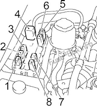
| № | Relay |
|---|---|
| 1 | Air Conditioner |
| 2 | Horn |
| 3 | Xenon: Right Headlamp; except Xenon: Dimmer |
| 4 | Headlamp Washer Control Unit |
| 5 | Front Fog Lamp |
| 6 | Rear Fog Lamp |
| 7 | Xenon: Left Headlamp |
| 8 | Theft Warning |
| № | Relay |
|---|---|
| 1 | Cooling Fan Relay 3 |
| 2 | Park/Neutral Position |
| 3 | RHD: Blower Motor |
| 4 | Cooling Fan Relay 1 |
| 5 | Cooling Fan Relay 2 |
| 6 | Engine Control Module (ECM) |
![]()