I just had the y-pipe installed today (5/2/98), so I have not been able to completely test it out, but my overall impression is very positive.
The installation took 2.5 hours (cusom design/install) and involved the cutting and re-welding of several components of the exhaust system. The O2 sensor was moved, and some new piping was added.
My first impression has been that the engine reves MUCH more smoothly and quickly. It also seems to run smoother at higher RPMs. Noise has not increased very much, but I did notice a difference.
Pictures:
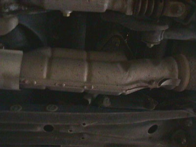
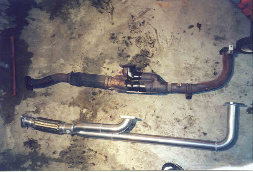
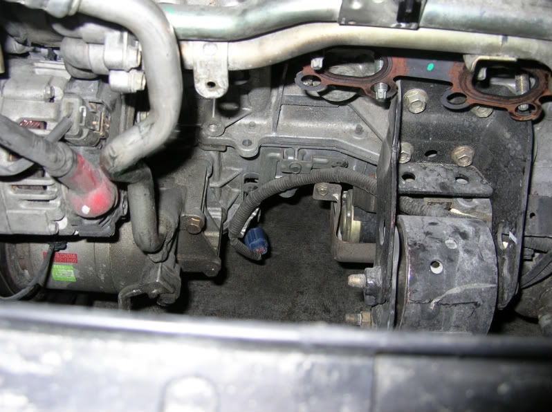
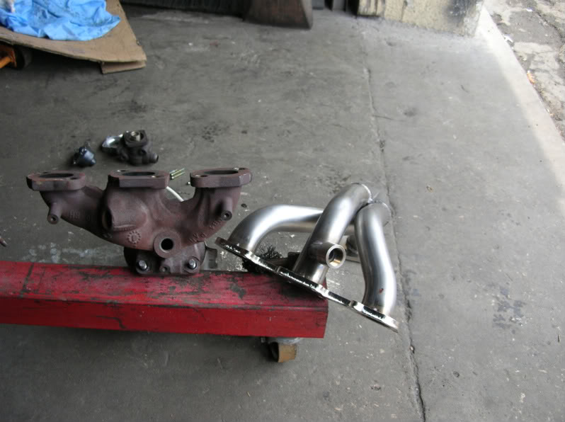
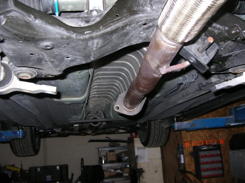
Stock Y-pipe:
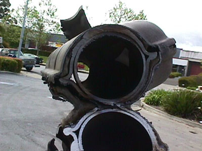
You can see that the stock y-pipe has two main sources of restriction. First, the runner from the rear exaust manifold heads towards the FRONT of the car before it enters the y-pipe at a 90 degree angle. Second, the stock y-pipe is made of two halves that are welded together, this does not allow a smooth coupling of the pipes.
Stock Y-pipe Removal:
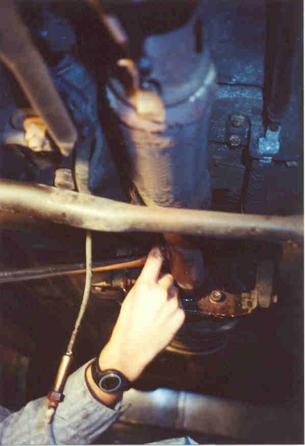
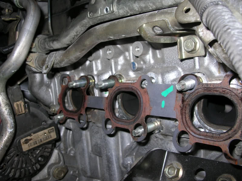
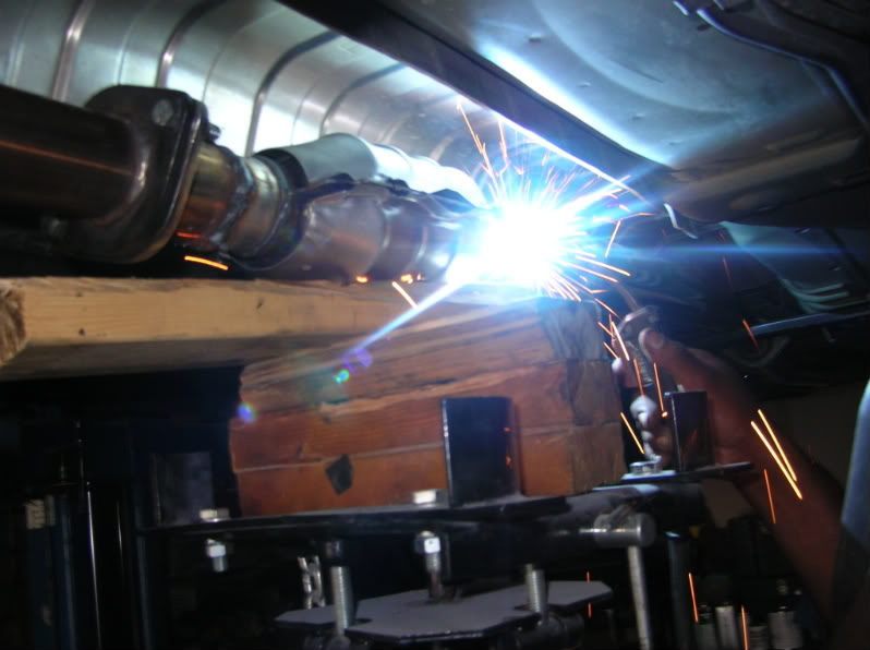
A Sawzall and a cutting torch were used to remove the heat shields from the stock y-pipe. Then the stock y-pipe, the flex tube, the O2 sensor, and the mounting flange to the rear exhaust manifold were removed.
New Y-pipe Installation:
The rear exhaust manifold mounting flange was saved and welded onto the new y-pipe.
The O2 sensor was re-attached between the flex pipe and the catalytic converter. The O2 sensor was relocated because the flex pipe had to be moved 3″ towards the rear of the car to make room for the y-pipe.
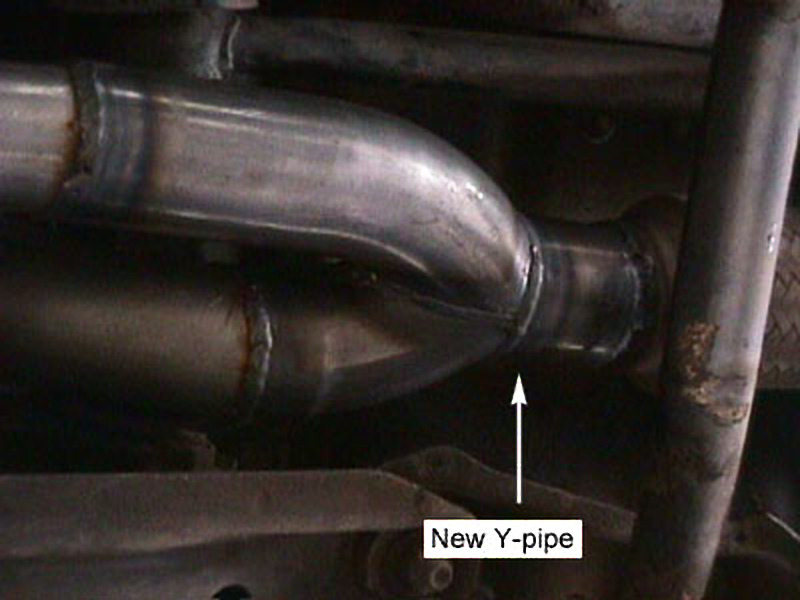
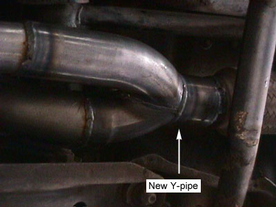
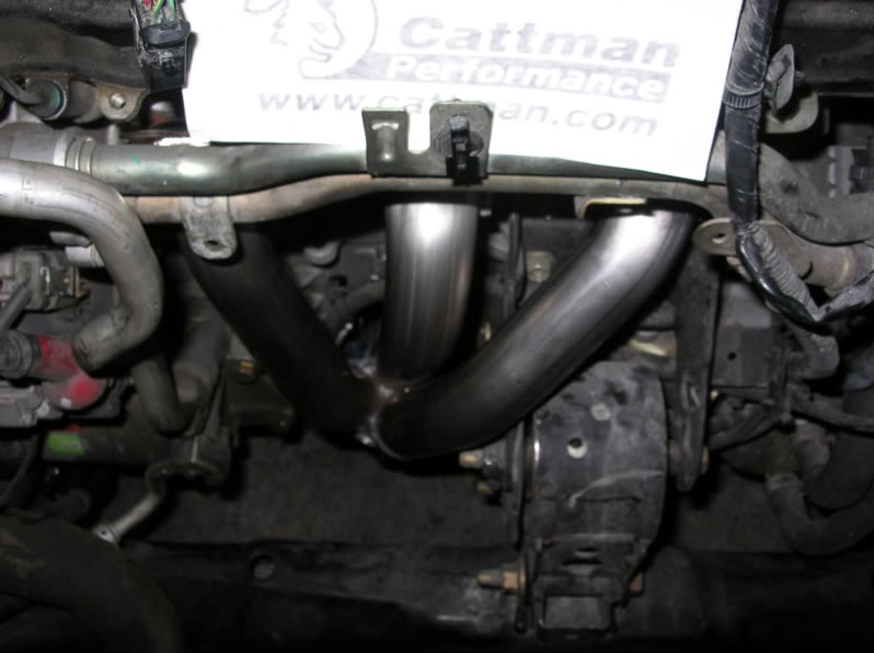
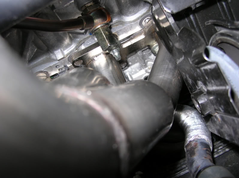
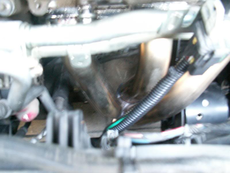
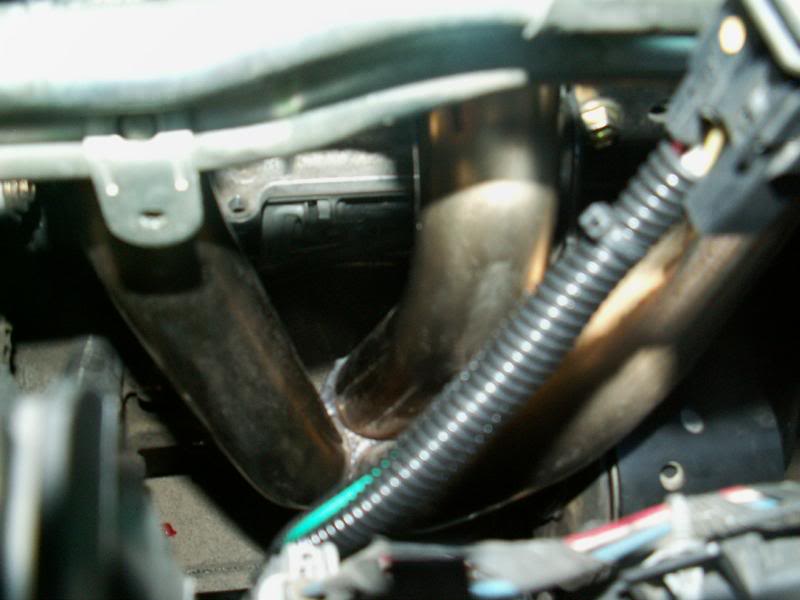
In this picture you can see the new Y-pipe. It is made out of mandrel bent stainless steel.
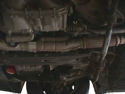
Finished Installation:
Here you can see the entire system. It is made of larger diameter tubing than the stock system, and the front and rear pipes come together in a less restrictive coupling.
All of the weld joints were painted to prevent rust.
Below are the procedures that I used in performing the replacement of six of my fuel injectors. I put them on this web page to serve as guidance for you, but do not guaranty the results nor do I proclaim this is the correct procedure, though I reference the Nissan Factory Service Manual, hereinafter (“FSM”), throughout. If you have any doubt on your capability in performing this replacement, take your car to a certified mechanic.
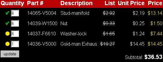
What you need : 1. Upper intake manifold gasket; part number 14033-89E00
2. Lower intake manifold gasket; part number 14032-89E01
3. Throttle body gasket; part number 16175-89E10
4. A.A.C valve gasket
5. New / remanufactured fuel injectors
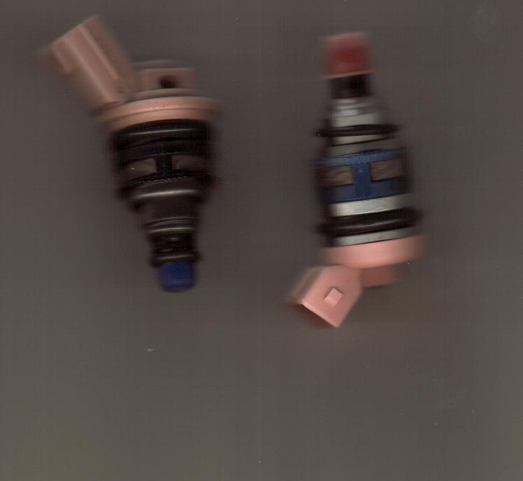
a. see the picture below, which depicts the two injectors with different connectors. b. The 90 -91 injectors have the metal clip (smaller) harness connector and the 92-94’s have clip-type (bigger) harness connector. c. Also, Nissan made both blue and black dot injectors for our cars. I have been told you can use either one, but can’t mix and match. I doubt it would hurt mixing and matching though, just so long as you get the right one for your car. The dot is on the harness connector. d. I picked up my remanufactured units for $37.95/ injector after the core deposit refund from Direct Automotive Product.
The injector on the left is a 92-94 injector, and the right is a 90-91, and probably an 89 too.
The steps I performed : 1. Release fuel pressure to zero
a. I did this by unhooking the upper hose from the fuel filter after pulling the fuel pump fuse
2. Separate the accelerator cables from the throttle body.
a. they easily just slide off. Tilt the butterfly valves back to get them.
b. Remove the cabling and routing from the intake plenum.
3. Remove spark plug wires from spark plugs.
4. Remove the intake elbow leading to the throttle body.
a. there are three bolts, the middle one is the longer one and routes the spark plug wires.
b. These bolts are torqued at 13 – 16 ft lbs.
For steps 6 – 9, basically remove necessary hoses and vacuum lines so you can free the plenum for removal. I took notes on a few of the items I might have forgotten when putting things back together.
5. Remove the A.A.C. valve
a. there are four 5 mm hex bolts holding this in. remove the harness connector also.
b. There is an “S” shaped hose connecting the AAC valve to the plenum, remove this also.
6. Disconnect throttle sensor
7. Disconnect the P.C.V. hoses behind the intake plenum
8. Disconnect vacuum hoses under the throttle body, from the E.G.R. control valve, master brake cylinder ,etc.
9. Remove the E.G.R. flare tube
a. this is held on by two nuts. I think they are 10mm in size.
10. Remove the upper intake plenum
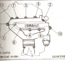
a. there are eleven six millimeter hex bolts that hold down the plenum at 13 – 16 ft lbs.
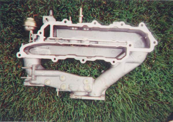
b. There is a special torque sequence that I observed in both loosening them and tightening them down. Please refer to the picture at the bottom of the screen for that sequence.
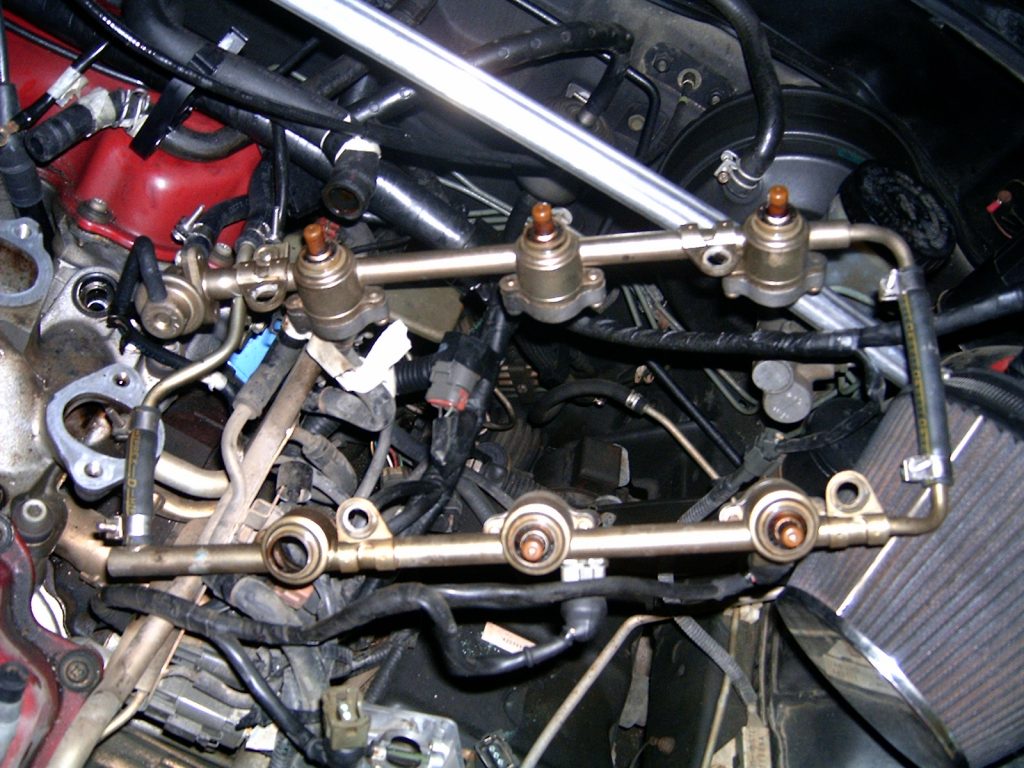
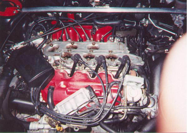
Less the spark plug wires and the throttle body (my procedure keeps it attached to the plenum), your engine should look something like the above before taking the lower intake manifold off. Pictures are courtesy of Matt Blehm.
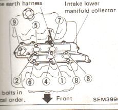
11. Remove the lower intake manifold collector from the engine.
a. Use the loosening sequence below for taking the manifold off and putting it back on. Again, reference the picture at the bottom of the screen.
12. Remove the engine earth harness from behind the plenum.
13. Remove the fuel injector harness wires
a. For the 92,93,94’s this is easy, as you just apply pressure on the harness and pull
b. For the 90 and 91’s (and presumably 89’s) there is a metal wire clip that you must pull out or partially out to remove the connector.
14. Remove fuel injector(s)
a. I used a pair of pliers and gripped them tightly, turning the injectors back and forth before pulling upward. All came out somewhat easily, except my last one.
b. There should be two O rings per injector for the 90 -91 injectors. I am not sure the 92,93,94 injectors have two. The lower O ring will likely stay in the fuel rail hole upon removal of the injector. Just stick your finger in and retrieve it. Be sure to replace with new “O” rings, per the FSM.
15. Replace injector(s)
a. I applied motor oil to the O rings and carefully inserted the new fuel injector. Instead of just pushing downward immediately, you should turn it back and forth, while applying downward pressure. You will see and feel the injector seat in how it should be. Before replacing, assure that the new ones spec out correctly with regard to resistance. The range of resistance allowed by Nissan is 10 –14 ohms .
16. Clean intake plenum, lower intake manifold, and intake runners.
a. I used Carb clean and a Valvoline product. I sprayed a good amount of Carb clean down the intake runners and used a cloth to wipe the dirt out. You may want to try a toothbrush.
b. Be sure to completely scrape away all remaining gasket material on both surfaces so as not to allow an intake leak after assembly.
17. Reinstall all parts in reverse order, keeping in mind the torque sequence and use the torque wrench so as to tighten the following to these torque specifications, per the FSM:
a. plenum hex bolts 13 – 16 ft. lbs .
b. lower intake manifold hex bolts, 13 – 16 ft. lbs .
c. A.A.C valve bolts – 4.6 – 6.1 ft lbs .
d. intake elbow bolts 13 – 16 ft. lbs .
The online HTML editor now supports the use of an external CSS file to be applied to format the content of the visual preview of your document.
This procedure is for the installation of an underdrive pulley. This requires removal of all 3 drive belts and possibly the starter. Nissan recommends changing drive belts every 30,000 miles. They should be checked periodically too. This procedure applies to the VE30DE engine, but is very similar for the VG30E.
My car was leaking oil out of the front main seal (behind the crankshaft pulley) so I figured if I was going to have to take off that pulley, I should go ahead and put a better one back on. For the VE engine (1992-1994 SE only), ASP Racing sells a lightened, smaller crankshaft pulley:
Auto Specialties underdrive pulley systems increase engine horsepower by reducing the amount of power required to drive external accessories. For example, the alternator, power steering, water pump and air conditioner all rob horsepower from the engine. By replacing factory-sized crank and accessory drive pulleys with a resized pulley, the accessories are slowed, resulting in more horsepower available to drive the rear wheels. Typically, a set of Auto Specialties street pulleys will increase output by 12 to 15 horsepower, resulting in quarter mile time improvements of .2 to .25 seconds.
I got mine at RPMoutlet.com. For the VG engine (89-91 SE and 89-94 GXE), Unorthodox Racing sells a lightened, smaller pulley. You can get this from Courtesy Nissan. Because the new pulley is smaller, you will need smaller sized drive belts which run about $10 each from most parts stores. Here are the Gates parts numbers for the belts you need (note: ASP gives a different part number for the power steering belt, but this is the correct one). I got mine at PepBoys and they are Dayco brand; the numbers are easily converted to Dayco numbers – 325K5, 378K4, 460K4. The number next to K means the number of grooves in the belt and the other number has something to do with the length (probably the circumference).
VE30DE
VG30E
Alternator
K050323
K040292
Air Conditioning
K040460
K040460
Power Steering (also drives water pump)
K040378
K040395
As you can see, the new belts fit just inside the old belts:
Tools you will need:
Various sockets: 10,12,14 and 27mm (for the crankshaft pulley bolt); you may need one or two other sizes, but nothing special besides the 27
12mm open end wrench
Socket extension
Torque wrench
Breaker bar
Flat head screwdriver
Impact wrench would be very helpful, but not necessary
Maybe: pulley remover
This procedure isn’t that complicated, but if you haven’t ever changed drive belts, it may be a good idea to have someone else check over your work before you put everything back together (especially important for power steering and alternator belts). Read through the instructions first before beginning any work. Also, you should buy a new front oil seal for your car. It’s about $3 from Courtesy Nissan and maybe $5 or 6 from a local dealer; you’ll have everything off to change it and you wouldn’t want to have to do this again if it starts leaking in a few weeks from now. The part for the VE engine is 13510-97E10; I’m not sure of the part number for the VG.
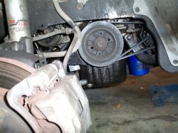
First, remove the right front wheel and remove the splash shields that cover the side and below the drive belts. There are a couple 10mm bolts holding these on. You should now be able to see the crankshaft pulley and drive belts
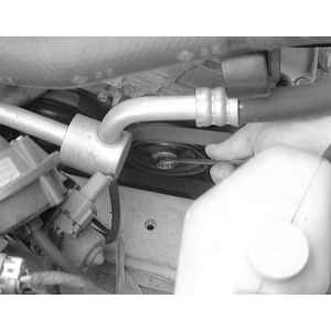
Start by loosening the 12mm bolt on the air conditioner’s idler pulley – this is the small pulley just in front of the A/C compressor. This will be more of a pain if you have ABS, but it’s still not that bad. I used the flat open end of a 12mm wrench to get the bolt and then loosed it that way. Dont remove this bolt, just loosen it a few turns. Now there is a bolt pointing straight up just behind that pulley that you need to adjust to move the pulley down (see picture below). If this bolt is hard to turn, make sure the bolt through the middle of the idler pulley is loose enough; dont force it or you could damage the idler pulley tracks. You need to lower it enough so the belt has enough slack to pull off of the A/C compressor. The pictures below are with the large radiator hose removed so you can see where the bolt is.
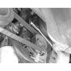
Now you need to remove the alternator belt. Loosen (do not remove) the bolt at the bottom of the alternator that goes into the alternator adjustment bolt (first picture). Also, loosen the alternator pivot bolt near the top of the alternator (second pic). Now you can loosen the alternator adjusting bolt (third pic). In my case, the bolt loosened but alternator did not move, just move the alternator with your hand to the point where the bolt is tight again. Loosen this until you can pull this belt off.
Now you need to remove the power steering belt (which also runs the water pump). There is another idler pulley for this system. Just loosen the center nut for that and lower the idler pulley until you have enough slack to remove the belt.
If you are not putting on an underdrive pulley and just want to change drive belts, skip the next couple steps:
Remove bolt in the center of the crankshaft pulley. This is where you need the 27mm socket. This bolt is on very tight; if you have an impact wrench, this is a great time to use it. Otherwise, you’ll probably need a long breaker bar. Chiltons recommends removing the starter and placing a flat blade (your hubcap removal tool in your Nissan jack set in the trunk should work fine) in the teeth of the flywheel/driveplate.
If you have a manual transmission, put the car in 5th gear. The starter is easily removed; if you are going to remove it, you should unplug the negative terminal of the battery first so you dont short anything while removing the starter’s power wire. The starter is only held on by a large wire, one 14mm nut and one 14mm bolt.
If you remove the rubber protective covering over the large wire, you will find a nut under there; just remove that and the large wire will come off. You will also need to unclip a smaller ground wire from it’s harness. Then you can remove the 14mm nut and bolt that hold the starter onto the transmission. After these are loose, the starter will just pull off and you should be able to see the flywheel.
If you have an automatic, there should be a small cover over the lower part of the transmission that you can remove to see the driveplate.
Then wedge something in between the teeth and prop it against something solid. You should now be able to break loose the crankshaft pulley bolt.
Now you can remove the crankshaft pulley. Mine could be pulled off by hand; if not, a 2 or 3 jaw puller can be used to pull it off. You will notice how much larger and heavier the stock pulley is compared to the new pulley.
The old oil seal needs to be removed now. It is just around the inner edge of where the pulley was. Use a flat head screwdriver to gently pry this out. Be very careful not to scratch or damage anything other than the seal. Now the new seal just needs to be pushed in place (you should lube the outer edge with some engine oil, the inner edge is already lubed). Put it in place and gently push the edges in; I used a rubber mallet to help push it in. The first picture shows the seal still on and the second shows the seal removed.
The new pulley will be very tight to get on. Some have hammered it on, but I would NOT recommend this. I used my dremel to shave off some material from the inside diameter until it fit better. On mine, I could feel a small difference in diameter between the inside edge of the new pulley and the rest of the inside diameter; I ended up dremeling the inside until it was all the same diameter as the end portion. Just use sandpaper, a dremel or whatever to remove a small amount of metal in there, but try to do it in a circular way so it’s even throughout. When I was done with this, the new pulley fit on better. I got it on part way and then put the large bolt in the middle and tightened it to help push the pulley on. Now you need to torque the pulley bolt to 123-130 ftlbs for the VE or 90-98 ftlbs for the VG. You can now put the starter back on (or cover plate for the automatic tranny). Also, you can now reconnect the battery if you unplugged it.
Now you are ready to put the belts back on. This is just the opposite of how you removed them – put new belt over the pulleys and tighten the adjustment bolt and then tighten a bolt to lock the adjustment (and for alternator, tighten pivot bolt). If your belts are too loose, they may make a squeling sound when you start the car and may slip a little. If they are too tight, they could cause lots of other problems so it’s important to get the tension right. The picture below shows the test point for each bolt as indicated by the arrow. If you push or pull down on this point it should move a certain distance for each new belt. Alternator: 6.5-7.5mm, A/C: 5-6mm, power steering: 6.5-7.5mm. This is where it would be helpful to have someone who has done drive belts before to check the tension for you to be sure.
Once the belts are on and tighten, check the 2 idler pulleys and the alternator adjustment bolts to make sure they are all tight. Start up the car and take a look at the belts and pulley. My pulley looked like it was a little off center, but I realized it was just the washer in the middle of the pulley was tricking me because of the silver color of the pulley and the black of the washer. Look at the edges to be sure. Check that all the belts are turning smoothly and are not at all crooked or not in their grooves. Now just replace the splash shields and that should be it. Check the pulley and belts again in a couple days just to make sure everything is still in place.
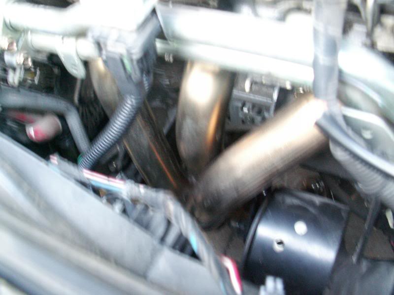
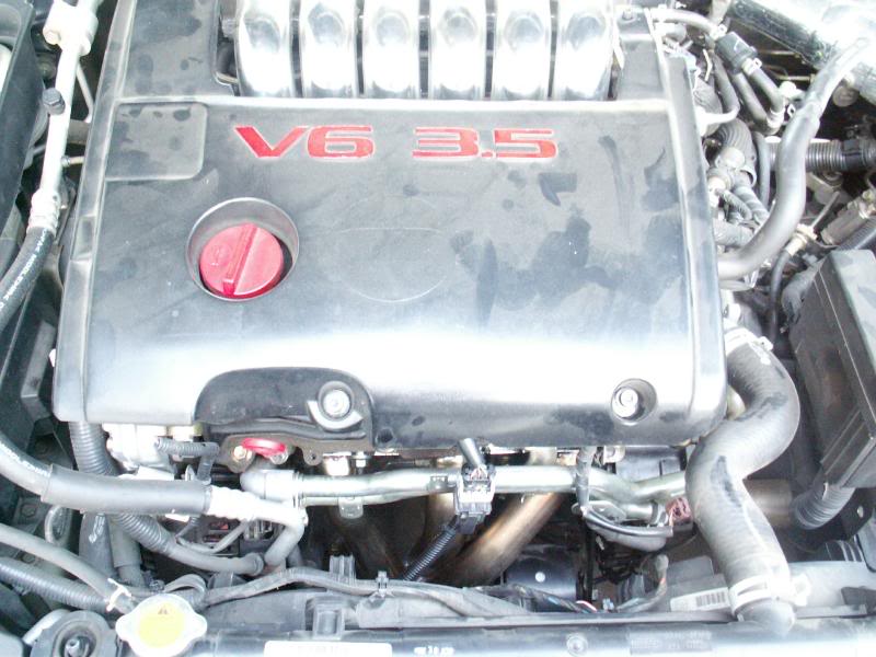
I had a custom “y pipe” for my older white Maxima. In actuality, it is an “f” pipe that aids in the exiting of exhaust. Unlike a true Y pipe, the rear manifold exit drops down straight into the pipe from the front manifold. The exhaust gas is freer flowing and it certainly made a difference, but not as much as the true Y pipe.
I did things differently with my black car. I wanted it to be faster and more responsive than the white Maxima and I have accomplished that. I installed the Cattman Y pipe. It is a completely bolt-on piece that was not terribly difficult to install. I recommend taking the time and soaking all the bolts/nuts prior to taking them off. You will also need to purchase exhaust gaskets, which are also shown in my installation pictures below.
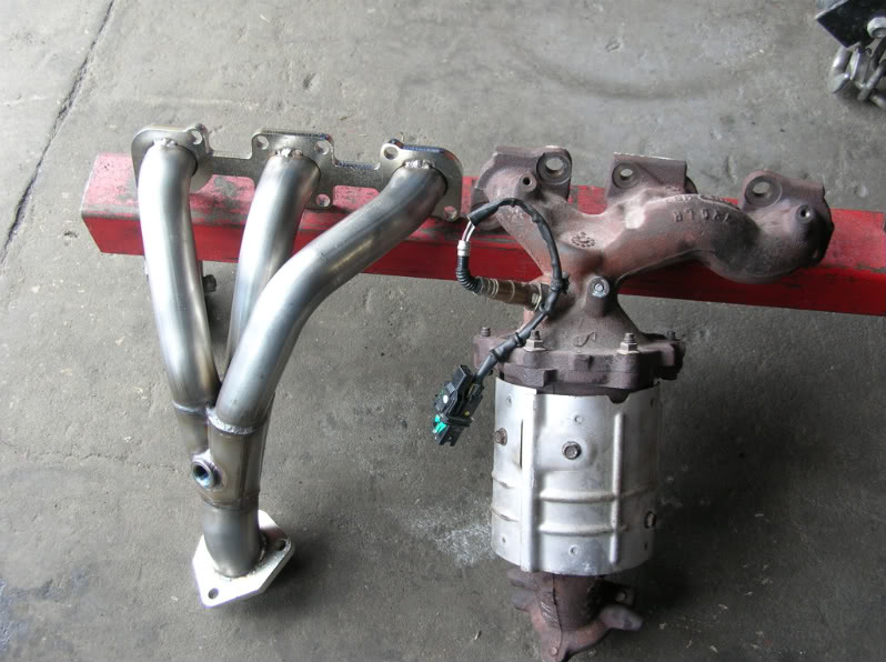
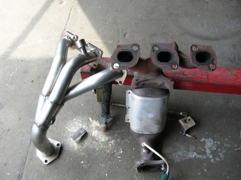
In comparing the pipes, you can see how the flow is impeded in the stock pipe. Also note that the Cattman pipe has a longer drop from the front manifold. I believe this causes a problem with the pipe hitting the sway bar. Also note how the stock pipe drops a bit in order to get to the Catalytic converter, this just goes to show you that the stock pipe sits higher. If the Cattman pipe would have incorporated these two things I mentioned, it would have plenty of clearance from the sway bar. I believe Warpspeed performance solved this aggravating problem.
Tools you will need:
1. Metric Socket set (some SAE may actually work though, as I found out for my front catalytic converter bolts)
2. Metric wrenches (to reach up in some of the more difficult bolts
3. Breaker bar (at least an 18 inch socket wrench as these bolts are tough to take off)
4. Liquid Wrench spray (or a similar product- I used a synthetic Valvoline product)
5. 3 gaskets (two for the manifold connections, and the other for the catalytic converter.
5. Goggles! (else you’ll get all kinds of crap in your eye)
6. A light for under the car
7. Duct tape and aluminum foil if it hits your sway bar after your done (because of a soft rear motor mount)
8. A jack and jack stands
Here’s the pipe and the gaskets I used.
Step1 : Patrick using the lubrication. Valvoline synthetic lubricant was used to loosen all bolts. My advice is to let them soak on the bolts for a few hours prior to trying to remove them. This will make your job much easier.
Step 2: Yours truly, taking off the shields and brackets. At this point, the jack in the picture is a backup in case my jack stands fail, don’t worry, no upward weight on the transmission there.
Step 3 : Using the breaker bar to take off the Catalytic converter bolts.
Step 4: Loosened those nuts on front manifold.
Step 5: Instead of taking this bracket off like the most of you probably did, I took my electric hacksaw and sawed off the end of it, giving the Y pipe just enough room. Note how the bracket will work with the crossmember and help absorb an impact if I hit something low. Pictured is me holding the piece that I cut off.
Step 6 : Note that the Y pipe is protected both by the bracket and the cross member. I was lucky to get one that did not hang lower than the cross member. However, the sway bar problem that I have and that I mentioned in my FAQ’s could have been avoided if this drop wasn’t so severe. It looks like there is plenty of clearance now, but the car/engine is jacked up somewhat. This is how it should have been!
Step 7 : The finished product, before hooking up the catalytic converter hangers.
The result? A lot more power between 3000 and 4500 rpm, however, the pipe hangs too low and vibrates on the sway bar during moderate to heavy acceleration. I ended up passively fixing the problem by padding the sway bar. In addition to my padding of the sway bar, I had to dent the pipe a little bit.
Extract or delete some HTML tag attributes from the desired tags, based on your criteria with the online HTML editor. Other useful features will help you to make web content composing a piece of cake.
I was successful in repairing my broken exhaust manifold studs. Below is my exact procedure I used. I took some video and some pictures, which I will post also. Half of the time for this procedure will be spent in removing the components in order to get to the manifold, the other half involves a delicate procedure for proper extraction of the broken. My manifold was also warped. I’m not sure if it warped and caused the stud break or if it warped after the stud broke. Whatever the case, I had to have it evened out with milling machine. A special thanks to Matt Blehm, who gave me some excellent points and direction in this process.
Before starting the procedure, it is almost essential that you spray the bolts that you can with a “liquid wrench” type lube. I would suggest making this project a two day project by letting the fluid soak over night after taking the components off and exposing the studs.
Here are the part numbers that I used. These are the studs from the turbo VG engine, which are recommended for our application. I got part of my order for Nissanparts.cc from the Internet. They have the best prices I have seen. Unfortunately, I had some delay in shipping and had to go local for my others.
1. Disconnect the negative terminal on the battery .
2. Jack the car up and support it properly, locking and blocking rear wheels .
a. If you don’t feel you can support it correctly or don’t have the equipment, take it to a professional.
3. Remove the two splash shields on each side of the cross member under the car .
a. 10 mm bolts.
4. Remove the elbow leading to the throttle body .
a. There are a total of three bolts, two on each side and one in the center that also supports the spark plug wires.
b. Pull the two rubber tubes going to the elbow.
5. Disconnect the radiator shroud .
a. The transmission cooling lines are routed at the bottom of the shroud. Pull those off.
b. There are two electrical harnesses, pull those off after labeling which one is at the top.
c. There are a total of 5 screws that hold the shroud in, three at the top and two at the bottom.
6. Remove the air conditioner belt .
a. Loosen the nut in the center of the air-conditioning belt idler pulley. This will allow the belt to loosen when you loosen the tensioner bolt.
b. Loosen the air-conditioning belt tensioner bolt, which is a 12 mm adjuster located above and to the left of the pulley. Loosen around 15 turns or enough slack to remove it, picture shown.
7. Remove the alternator belt .
a. See the step-by-step procedure I followed for replacing the alternator on my alternator page, here .
8. Remove the alternator. Again, instructions , here .
9. Remove the air conditioning compressor .
a. Now that the alternator is removed, you can remove the two lower air conditioning bolts on the bracket. I suggest loosening all four of them first.
b. Get to the top two bolts from under the hood.
c. You will not have to disconnect any hoses. Just move it out of the way. I brought mine up and rested it on top of my engine on the left side, without over-stretching any hoses.
10. Loosen the exhaust gas recirculation copper pipe from the manifold .
a. Before pulling this out of the way, try to unscrew the other end of the copper pipe. I could not get this off. You’ll need a long wrench for plenty of torque.
b. I used some considerable force to pull this out of the manifold. It is flexible material and I had no problems bending it.
c. You will need it out of the way in order to drill, particularly on the cylinder 6 chamber.
11. Move the oil dipstick tube out of the way by first taking off the two small bolts that hold it in place .
a. Again, I bent this tube out of the way, towards the radiator.
12. Remove the manifold nuts carefully and remove the manifold .
a. You may have more studs snap, be slow on un-loosening the nuts.
b. Scrape away any existing gasket. I used sand paper on both surfaces to clean them up.
At this point, you’ll want to use a straight edge of some sort in order to determine if your manifold is warped. Mine was. I’m not sure if the warp caused the stud to break or if it warped because I drove with it broken for two months. Probably the latter. I took my manifold to a machine shop, where they milled the surface with a milling machine so that it was square again. I’m not sure of the cost because I had mine done for free. I stood there and watched. It took about 30 minutes.
13. Use a Center Punch and carefully punch the center of the stud in the head .
a. This is an important step. Be sure that when you tap the punch that it’s dead center.
b. Alternatively, Matt mentioned a safer but more time consuming method that can be used, which will ensure a more accurately drilled hole. This involves taking a broken piece from a stud and drilling through it on the workbench. Next screw the pre-drilled stud in partially in the head, where a broken stud exists. Then take a drill and guide it through the stud that you pre-drilled. This will ensure a centered hole.
c. I learned that it is not so imperative that you drill perfectly into the center of the stud. I was accurate enough to successfully drill in the centers, except for one. I got into the threads on my first attempt because of a poor center punch attempt. I ended up using a simple heli-coil kit, which required a 21/64 drill bit. This is further explained at the end of this document.
14. Carefully drill into the studs .
a. Don’t be concerned with using the biggest bit you can at first. I used one that was a little less than half the size of the stud and then worked my way up a couple of sizes before using the EZ out.
b. Be sure you are steady with the drill. Do not use too much pressure.
c. You’ll be on your back in an awkward position – endurance is key.
d. You don’t have to drill in very far. The broken stud is only about .25 inches long.
15. After creating a successful hole, spray some solution into it and get your EZ outs ready .
a. Use the biggest EZ out you can for the hole you created. The bigger EZ out you have, the lesser chance of it breaking.
b. I prefer using the spiral EZ outs, but use whatever you’re comfortable with.
16. Carefully tap in your EZ out and then back the stud out, using a wrench or vice grips .
18. Once you have the studs out, insert the new ones. I doubled up with two nuts to screw them in the head .
19. Replace the manifold and all components .
If you drill improperly or drill into the threads, do not panic. I simply used a heli-coil kit, which came with individual heli-coils and a tap. I had to supply the recommended 21/64 drill bit, which I had. After inserting the heli-coil, the stud screwed perfectly into it. In fact, this stud felt more secure than the others! I believe I used the 21/64″ Drill for 5/16″ Coil Kit, but I think this one would be an exact match: M8x1.25 x 12.0mm, using a 21/64 drill bit. Here’s a picture of a heli-coil:
I used a friend’s kit, which required only one heli-coil. I believe a kit will cost about $30.
Member Credit: THE PRESENCE, EddyMaxx & DeusExMaxima
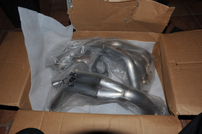
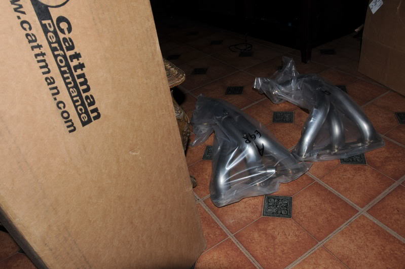
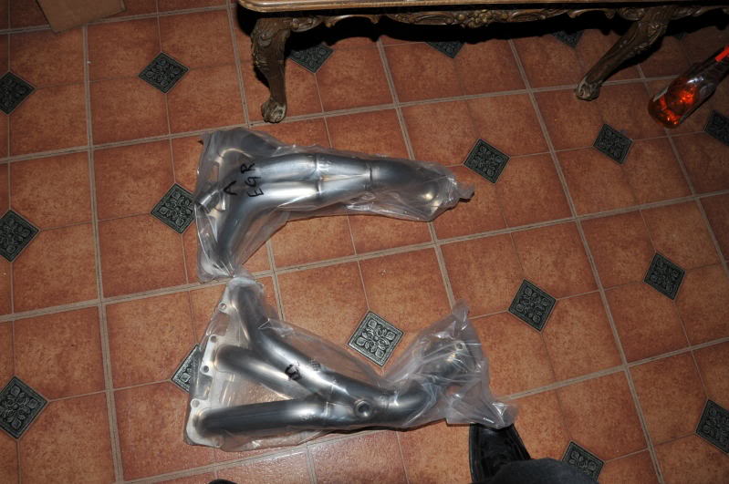
Unboxing Cattman photos from Eddy.
This is a project that I will never forget. Actually, me and my mechanic had fun with the install.
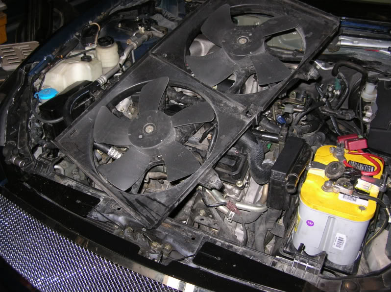
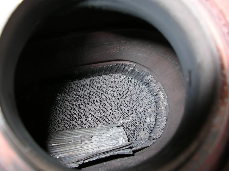
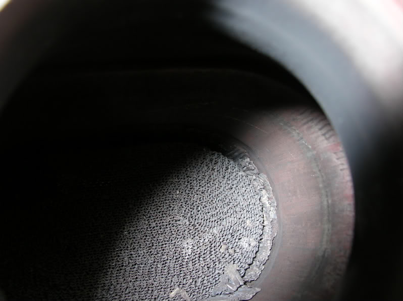
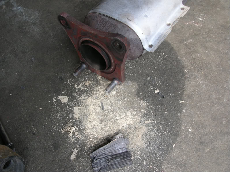
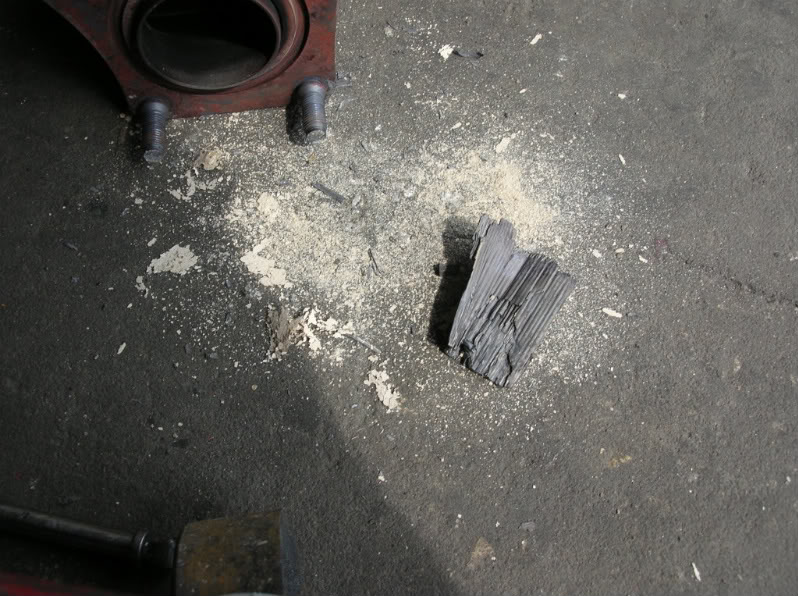
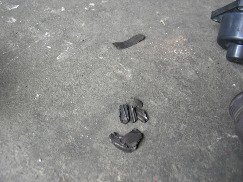
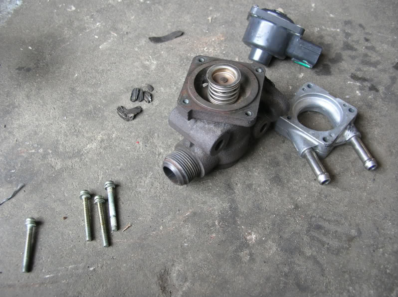
This is why I had to purchase a set of Cattman Headers. The precat facing the front grille wasn’t so bad but definitely needed to be changed. Now, the precat facing the firewall was absolutely terrible. So terrible that the catalytic material completely jammed up my EGR valve pretty bad. Anyone that gets the SES light> P1402 code try your hardest not to ignore it. Below are some pics of the EGR valve taken apart and cleaned. Along with some of the bad catalytic cone material break-up.
This is all the crap that came out the Egr valve alone.
I had my mechanic weld a High Flow Cat on that I purchased from Advance Auto Parts. I’m just waiting to weld on the o2 sensor bung and extend that last o2 sensor wire. Instead welding the High Flow Cat onto the Racingline Y-Pipe. We just welded it on 6 to 7 inches further back.
Welding on the High Flow Cat
Additional Photos from DeusExMaxima
Original Pricing Below (This is for reference purpose only. Pricing is from 2010):
Headers only, AT or MT version, no EGR port (07/08 Maximas) – $599.99 retail, $569.99 w/ org discount
Headers only, AT or MT version, with EGR port (04-06 Maximas, 05/06 Altimas) – $629.99 retail, $598.49 w/ org discount
Y-pipe only, AT or MT version, NO cat and NO “extra” O2 ports – $379.99 retail, $360.99 w/ org discount
Y-pipe only, AT or MT version, WITH high-flow all-metal cat and NO “extra” O2 ports – $579.99 retail, $550.99 w/ org discount
Y-pipe only, AT or MT version, WITH high-flow all-metal cat AND two O2 ports behind the cat – $599.99 retail, $569.99 w/ org discount
Header/Y-pipe system, AT or MT version, NO cat or “extra” O2 sensors – $939.99 retail, $892.99 w/ org discount; add $29.99 for EGR port
Header/Y-pipe system, AT or MT version, WITH high-flow all-metal cat and NO “extra” O2 ports – $1139.99 retail, $1082.99 w/ org discount; add $29.99 for EGR port
Header/Y-pipe system, AT or MT version, WITH high-flow all-metal cat and TWO O2 ports behind the cat – $1159.99 retail, $1101.99 w/ org discount; add $29.99 for EGR port
Note from Cattman:
Because installation of the headers requires removing the precats, its necessary to make the secondary O2 sensors happy (because they monitor pre-cat function) to avoid related error codes. In a 2004 Maxima, this can be done with an O2 simulator or by installing a main cat in the y-pipe, followed by two O2 ports for the secondary sensors. This is not confirmed, but it “appears” that an O2 simulator will not fool the ECU in 2005 and later Maximas and Altimas, so installing a cat and two O2 ports in the Y-pipe may be necessary to avoid a CEL.
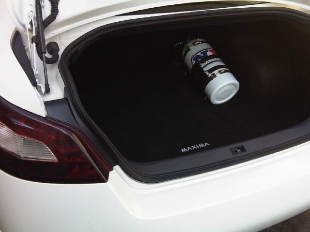
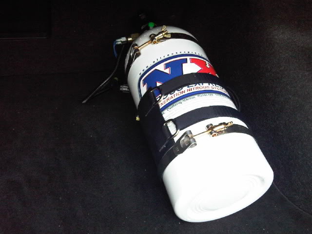
This is the first 7th gen CVT Maxima putting down some real power , I also realize i am the guinea pig for testing this CVT and seeing how much it can hold (so you guys gotta give me some credit lol). This was done in July of 2010.
Got some goodies along with it , purge kit and a bottle warmer.
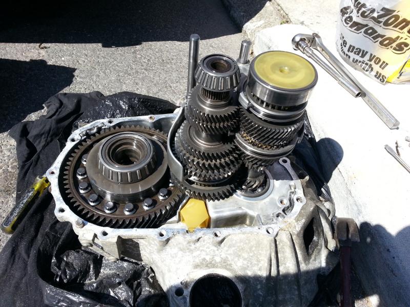
This is not a guide by any means, just familiarizes you with what is involved. This is not a job for someone who doesn’t have intermediate/advanced wrenching skills – so you’ve been warned. It took me a week to disassemble my first 5spd back in 2005, now ~3 hours.
If you are not familiar with how a manual transmission works internally, or are not confident in your abilities or can’t deal with issues when issues arise – leave this job for someone who knows it well.
I did not show the disassembly of shift forks/pins/how to set the check ball system/reverse gear/proper way to re-shim new bearings and other complex parts of rebuild, so once again this is NOT a how-to guide in any form or shape – I’m just posting pics of my progress.
BEARINGS SEALS PART NUMBERS
All ordered from Nissan = NACHI/NSK/NTN high quality Japanese bearings.
I’ve seen cheap kits with unknown bearing brands (made in china) and would not recommend using them due to the questionable quality of bearings
Input shaft bearing 1 – 32203-03E13
Input shaft bearing 2 – 32203-03E00
Main shaft bearing 1 – 32273-79E00
Main shaft bearing 2 – 32223-79E62
Pass side diff bearing (open diff – 2X) – 38440-96E00
VLSD driver side diff bearing (EXPENSIVE) – 38440-79E01
Input shaft seal – 32113-03E00
Shifter yoke seal – 32858-03E00
pass side axle seal – 38342-81X01
VLSD driver axle seal – 38342-51E00
open diff driver axle seal – 38342-81X00
How do you know if you have open diff or VLSD (the dumb way – look at the transmission)?
If axle seal is small = open diff (left)
If axle seal is large = VLSD (right)
Now that you know what transmission you have you can get the proper seals/bearings.. not gonna be cheap (VLSD bearings are ~$450)
Starting disassembly
Shift forks, main/input shafts and diff is out
OLD bearings off
OLD bearing leftovers
Shift yoke out
Cases cleaned
Yoke with new seal and boot in
New bearings pressed on
Assembled and sealed (need to swap speed sensor)
Old Transmission Out
VLSD Transmission going in
NEW axles, NEW throw out bearing
and that’s all.. fun times y0!!
If anyone remembers MAXUS09. I broke a shift fork on my 5spd during the last pass at MIR (shifting into 4th). Drove back to hotel in 4th gear only, pulled my trans out in hotel parking lot to find what broke inside. I got a blown tranny brought by ghostmax/i2vicious for parts (BIG Thanks again MD guys, and to NWP Aaron for the mat and jack I borrowed!!!)
I took that blown tranny apart for the part I needed, fixed my trans with it, put it back into the max, and drove all the way back to NYC.
If any of you with a manual tranny notice you have to fill up the clutch reservoir every few days, its probably because your slave cylinder hose has a slow sweat (common problem it seems). I changed it today in about an hour and a half (this writeup should get that down to half an hour). The hose itself costs around $40. I picked mine up at Cox Nissan (Bronx, NY), as they were one of the few who had it in stock. Here goes:
Tools needed – 10mm and 12mm wrench, 12mm socket. 1 – 2 bottles of DOT 3 or 4 brake fluid.
DISCONNECT THE + and – TERMINALS OF THE BATTERY
You’ll be working right over the battery, the last thing you want is to graze the terminals (goodbye armhair). Also, you’re gonna want the car to be cooled down for this, there’s coolant hose etc right there. Wait at least 4 – 5 hours after a drive to tackle this…
Step 1: Remove banjo connector coming from master cylinder
This was pretty simple. There is a 12mm bolt on top of the ‘box’ side of the slave cylinder hose. Remove this with a socket wrench and an extension (you don’t need the extension, but getting leverage down there is hard as ****). Clean it up, and then put the bolt aside. Get into the car and press down on the clutch 5 or 6 times to empty out the reservoir (might as well start off with clean brake fluid). The clutch will fall to the floor, so you’ll have to pull it up with your hand. Seperate the banjo connecter from the box. Notice the brass washer that comes off with it; clean that up and set it aside.
‘Box’ end of clutch hose:
Brass washer:
Step 2: Removing slave hose from motormount
The ‘box’ end of the hose is attached to the motormount by 2 screws, 10mm in size. Either a socket or wrench will work. You have to unclip the massive wire connecting the battery to the starter (leave the starter end of the wire attached, just push the wire over a little with the wrench while your removing any bolts), the clip will then come off with the box end of the hose.
Step 3: Removing hose from slave cylinder
Pain in the *** right here. This thing is on TIGHT so find the longest 12mm wrench you own and go at it. Just follow the other side of the hose up under the engine (you can see it if you get the angle just right from the intake side of the engine). I had a 5″ long wrench so doing this by hand was/is impossible. To solve this, I just went caveman style – get the wrench to hang on the bolt, then grab a hammer… Cracked it loose in 2 tries. Unscrew the rest by hand. There are 2 washers on that bolt – one above the banjo connector and one below. Now that you know, you won’t be dropping them somewhere inside your engine bay, right?
Step 4: Installing new hose
New hose (upside down):
Follow the steps you just took, backwards. Put the banjo connector on the slave cylinder side first (make sure you have one of those brass washers on each side of the connector). Screw that in tight. Do the same to the ‘box’ end with the hose attaching from the master cylinder. Attach the ‘box’ end of the slave hose + the cable holder piece (for the starter power cable) to the motormount.
Step 5: Bleeding the clutch
Once everything is nice and secure, you have to get all the air out of your hoses and replace it with brake fluid.
Some more pics:
Reasons to put down some newspaper in your driveway:
‘Box’ end with banjo connector + washer still attached (bolt removed already):
Brake fluid that leaked onto the clutch boot from the old hose:
Step I had to take to prevent the fluid from totally leaking out everyday (this slowed down the leak to a once a week topoff of fluid). Also, notice the blood on the left connector :
There you go; no more worrying about getting stuck in traffic with no fluid! Total cost should be around $50, hose + fluid (+ bandaids for burnt knuckles).
I just did my CVT transmission fluid drain/fill the other day, I’m at ~44,000 miles and premium maintenance service plan recommended every 40,000 while standard recommended every 60,000. With how I drive I figured it’s about time so why not. I got my fluid on fleabay, picked up 6 quarts for about $80 including shipping.
To start out, drive your car around and warm it up (yes warm it up). Park it and run your shifter through all the gears (D, N, R, etc). You will want to work on the car while it’s warm so be careful underneath touching metal.
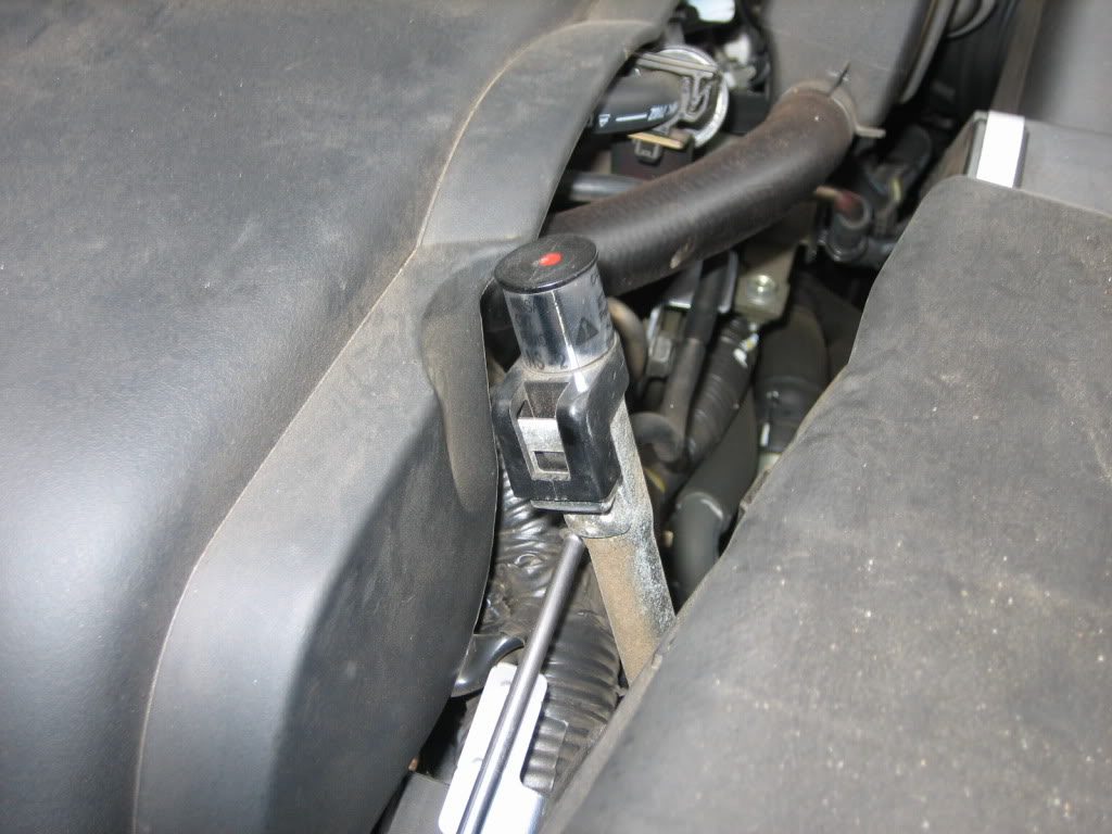
The process is this. Jack up the car in front; or use rhino ramps which make this job stupid easy. Get a 10mm allen key (this is a fairly large one so it may not be on your multi-tool, I had to go out a buy a specific 10mm one from Sears) and a funnel with a narrow tip to fit in the transmission inlet. The transmission dipstick in your engine bay is the round thing sticking up next to the main engine cover, more towards the driver side of that cover. It has some stupid child-safety plastic thing on it so idiots at Jiffy Lube or whatever don’t ruin your car by “topping off your transmission fluid” with standard stuff I guess.
Push in the black plastic tab with a flathead screwdriver and pull the dipstick out. Wipe it off, push it all the way back in (do it backwards so the child safety crap doesn’t lock), pull it out again. Your transmission fluid should be at the second notch near the bottom; remember that. Leave the dipstick out this time.
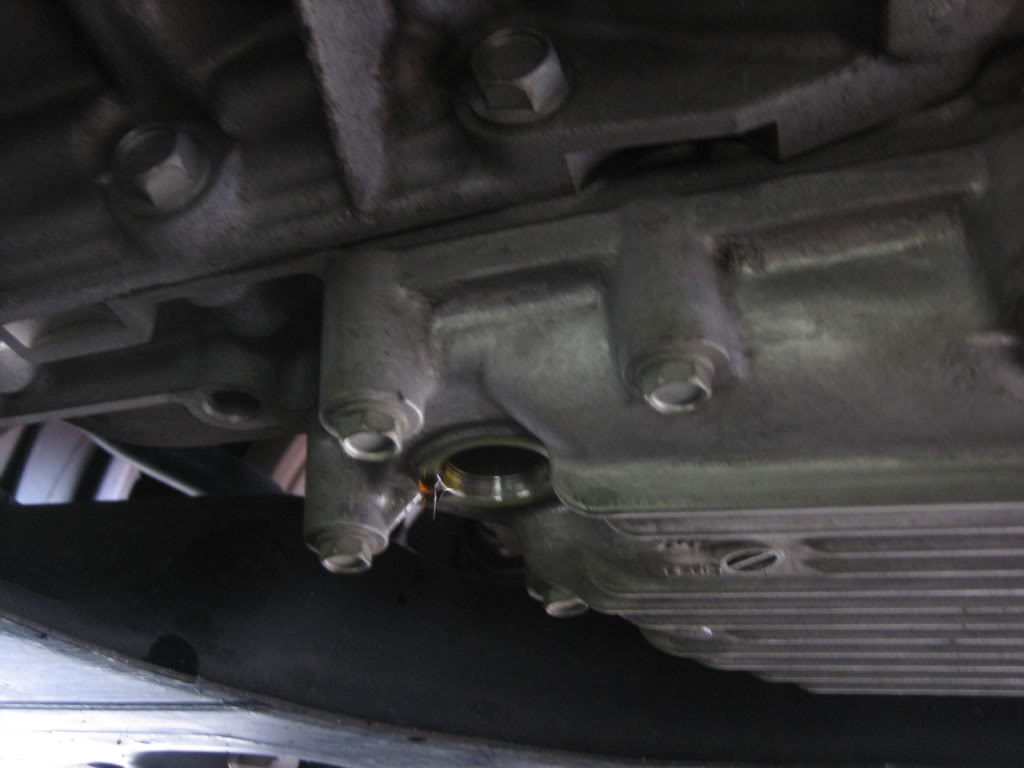
Get an oil pan, about 4-5 quarts of liquid is going to come out so you need a decent sized receptacle to catch it. Under the car look for a big metal piece that looks like this; here’s a picture of it with the drain plug removed.
Here is the drain plug you’ll remove, be careful the liquid is kind of hot and comes out pretty fast!
Let it drain for about 15 minutes. Then replace the plug (don’t torque it too hard, just get it nice and snug until you get a decent amount of resistance). Use a funnel and pour in the same amount of fluid you drained out of the car; you can start with 3 quarts and add .5 quarts at a time checking the dip-stick inbetween (remember, second notch). I ended up putting 4.5 quarts back in. When you’re satisfied with the amount of transmission fluid showing on the dipstick, replace the dip-stick and go drive the car. Don’t over do it, the car should have only released 4-5 quarts from the transmission through that drain plug.
Overall my impression is this. Car idles a little quieter, seems “smoother” to drive (as if the CVT wasn’t smooth already) and I’m seeing a .5 – 1 mpg bump in my daily commute which is a nice little surprise. Definitely worth saving the few hundred bucks doing this myself instead of having the dealer do it.
Part number for CVT transmission fluid: 999MP-NS200P. You can get this stuff on many websites, from the dealership, or on eBay.