Tag

Engine, Trans, F/I & Tuning

Browsing

Member Credit: Greg

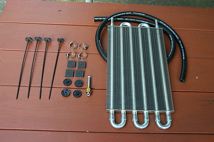
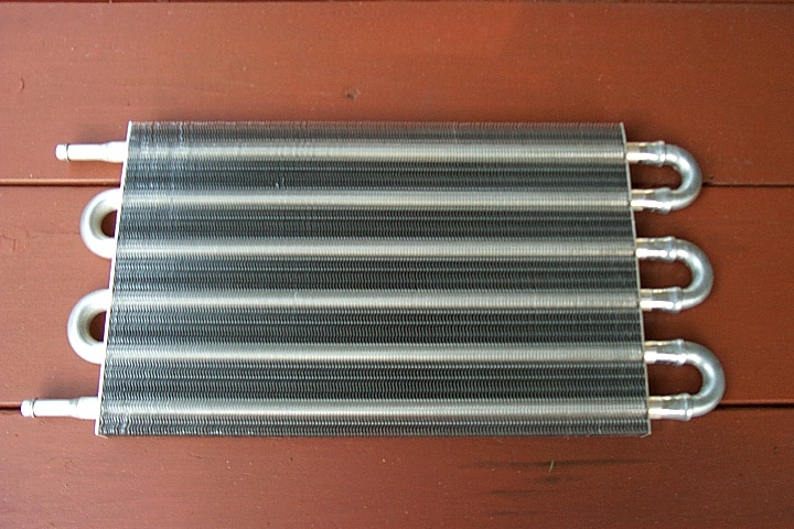
1.I bought the Hayden model 404 from Pep Boys for $49.99 plus tax. There were other smaller models, but I figured I would get the largest one practical. The 404 is considered “Heavy Duty” and is 7.5 inches tall by 15.5 inches wide, by 0.75 inches thick. It is supposed to lower your transmission fluid temperature by 70 degrees Farenheit. I would not recommend getting a cooler any larger than the 404, as it will be too big and difficult to install. In fact, the 403 would probably have been easier, as it is the same height, but 2.5 inches shorter.
Click the image to open in full size.

2.Here is everything that came in the kit. I bought an extra 4 feet of transmission cooler hose (not pictured) to use as the return line back to the transmission. The 4 feet of hose that comes with the cooler is not enough, since you will have to replace the stock transmission return line entirely. When you get the extra hose, DO NOT get fuel line, it is not the same. Ask specifically for transmission fluid hose!

Click the image to open in full size.

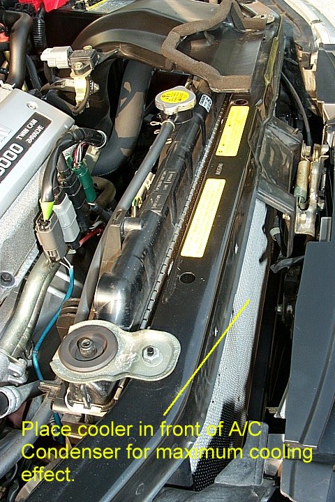
3.The picture below shows the A/C condenser before installation of the cooler. For optimal cooling effect the auxiliary transmission cooler should be mounted in front of the A/C condenser.
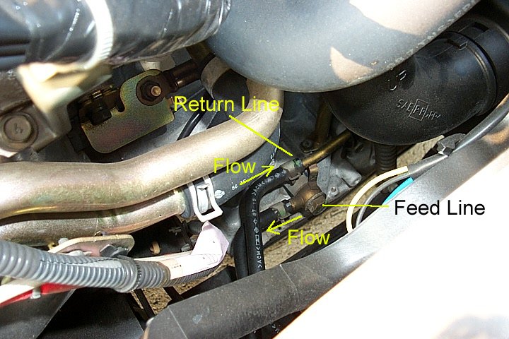
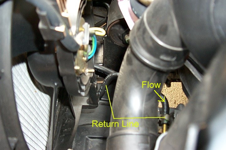
4.The cooler should be installed in “series” with the stock tranny cooler. To do this you have to locate the fluid return line. On the Maxima this is the upper line (without the “banjo” bolt). The two pictures below show the location of the transmission fluid lines before installation.
Click the image to open in full size.Click the image to open in full size.

5.It is necessary to remove the Driver’s Side Engine Undercover to expose the transmission fluid return line. The undercover is held in place with 7 bolts and one pop-on clip. I sacrificed the pop-on clip when I removed it. Casualty of tinkering with your car.

Click the image to open in full size.

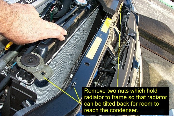
6.Remove the two nuts which hold the radiator to the car frame. You need to be able to tilt the radiator back so there is room to work.
Click the image to open in full size.

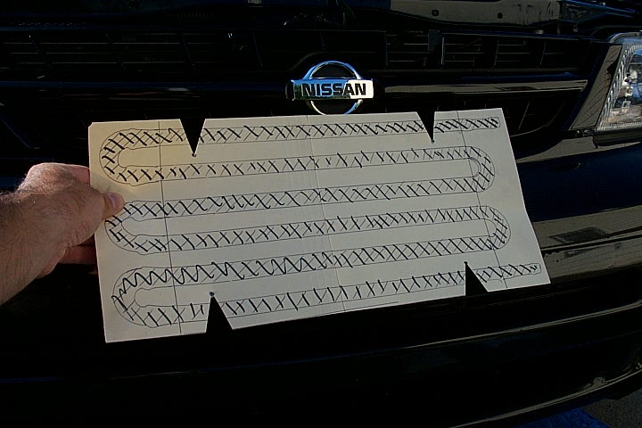
7.I traced out a template for the cooler on a piece of plain folder paper. The purpose of this was simply so I could line everything up and get an idea of how things were going to fit, how the hoses would hang and where, etc., before committing. It was also helpful in aligning the 4 holes where the zip ties would pass through the A/C condenser.
Click the image to open in full size.

8.The next step is to take each 4-foot piece of transmission hose and secure it with the clamps provided to the cooler. Then carefully slide the cooler in place in front of the A/C condenser. You can slide it in from the top or bottom, it really doesn’t matter – just be very careful not to bend or damage the fins on the cooler or on the car’s radiator. They are very fragile and will bend easily.

Click the image to open in full size.

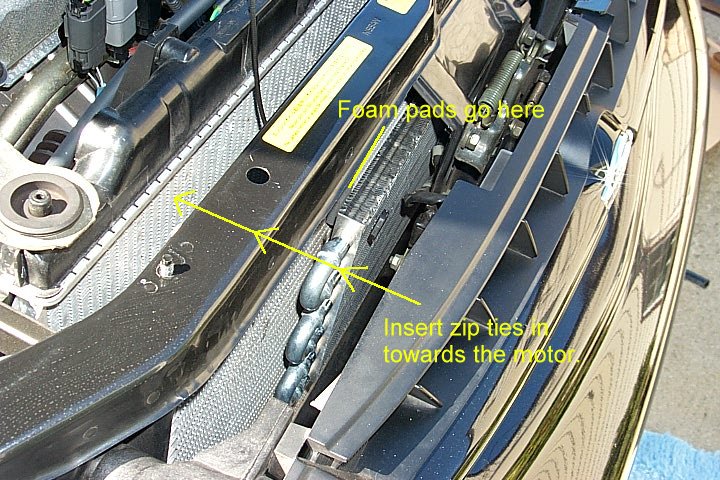
9. My personal recommendation is to insert the 4 zip ties through the cooler and the condenser from the grill side in towards the motor. It is much easier to do it this way and you will have a lot more room to insert the plastic cover caps in-between the condenser and the radiator than between the condenser and the grill. Trust me on this. Make sure to secure the 4 foam pads in between the cooler and the condenser before you insert the zip ties all the way through. This part takes a little bit of coordination, and a second hand wouldn’t hurt either.
Click the image to open in full size.

10. Once the cooler is secured properly to the condenser the next step is to remove the stock transmission fluid return line. The line is pre-bent and specialized for the stock setup and cannot be reused. The line is held in place at both ends by simple pressure clamps. I put a pan under the return line to catch about an ounce of transmission fluid which leaked out of the hose.

Click the image to open in full size.Click the image to open in full size.

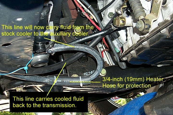
11. Take one of the lines from the Hayden cooler and cut it to length. Run this line to the radiator output port and secure with clamp provided. Make sure that the line is not bent or kinked and that it is away from the transmission pan. I bought some 3/4-inch (19 mm) heater hose from NAPA and wrapped it around certain parts of the hoses that I thought might rub or chafe. It is an added protection and a good idea, in my opinion. Secure the second line from the cooler back to the top of the transmission. I secured all of the lines with wire ties to ensure that they would not droop or move around too much.
Click the image to open in full size.

12.Here is a different view of how the hoses are routed from the cooler to the transmission.

Click the image to open in full size.

13.I used a heavy duty zip tie to hold up the top line and keep it from sagging. I later changed the zip tie to black for looks.Click the image to open in full size.

14.The transmission cooler is barely visible through the front grill and is in an excellent location to receive high airflow. The cooler will help out if you do a lot of stop and go driving or “spirited” driving that tends to heat up a transmission. In any case, it certainly won’t hurt anything, and is fun for about a 3 hour job. After driving the car around for a day I had to add about a half quart of ATF to make up for the added volume the cooler provides.

Loading

Member Credit: Greg

I took the Stillen Rear Sway Bar (RSB) off my ’99 Maxima before trading the car in and couldn’t wait to reinstall it on my 2002. I ordered new brackets from Stillen, because the trailing arms on the 2002 Maxima are much wider than the ones on my ’99, and the old brackets would not have fit properly. The bar itself can be reused.

I also bought all stainless steel hardware locally, to replace the Stillen hardware. For each side of the car you will need:

2 cap screws, 3/8-16×2.5 (top bolt holes).
2 cap screws, 3/8-16×3.0 (bottom bolt holes)
8 flat washers (3/8 hole)
4 stop nuts (3/8-16)

I found everything I needed in a West Marine store for very cheap. The stainless steel hardware will not rust as the Stillen hardware did after a few years. I reused the Stillen bushings after cleaning them up a little with a wire wheel.

I also reused the original Stillen aluminum spacers and M6 bolts for the E-brake cable.

This is how the trailing arm looks after removing the driver’s side wheel. The procedures are the same for both sides of the car.

Remove the 10mm M6 bolt holding the E-brake cable to the trailing arm.

Add the spacer and the supplied (longer) M6 bolt to hold the E-brake cable away from the brackets.

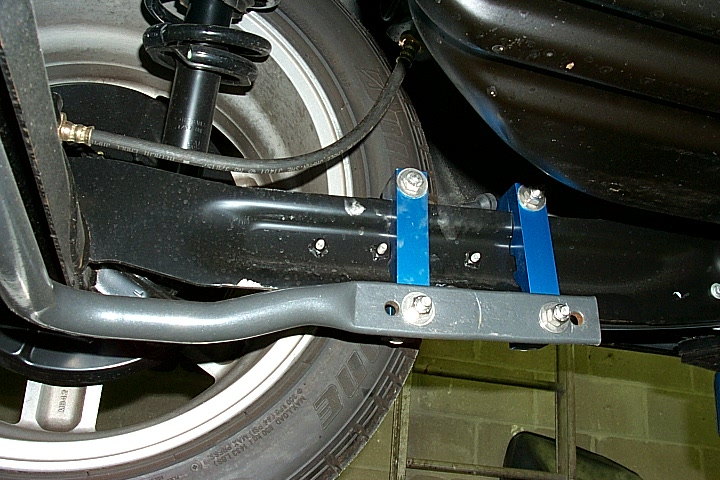
Here are the Stillen brackets installed on the trailing arm. Note that the nub on the end of the clip that holds the E-brake cable has to be bent slightly to clear the bracket. Also note that the bolt closest to the brake line has been turned such that it faces towards the outside of the car. It does not appear as though the brake line would rub, as it is pretty far from the bolt, but it is always better to be safe than sorry!

I used the 2 inner holes on the sway bar. Here is it mounted up to the car after all sides have been tightened. On the 2002 Maxima, Stillen recommends mounting the bar so that it lies right beneath the rear axle, however this is not easily done due to the positioning of the various ABS and E-brake brackets and clips, plus my bar was from a 1999 Maxima and Stillen is shipping bars for the 2000+ Maximas with extra holes (5 total) that allow it to be mounted right under the axle . My bar is mounted about an inch forward of the rear axle, which is fine. The further forward you mount the bar the more effective it is in the corners anyway.

The rear sway bar is one of the most effective suspension modifications you can perform on the Maxima. It virtually eliminates body roll during hard cornering and really tightens up the rear end of the car.

Loading

Member Credit: Greg

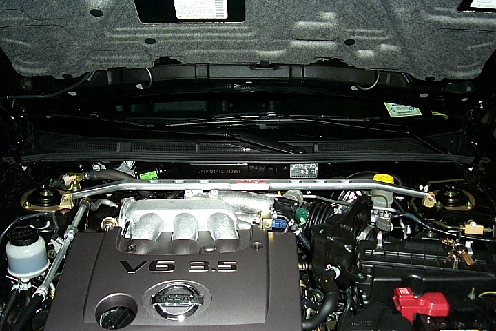
Stillen Front Strut Tower Brace before install. The simple purpose of this ingenious device is to lock the tops of the shock towers together in the engine compartment. Result is the suspension “box” is complete, and the car corners much flatter than stock, with a greater degree of stability. This wonderful device can be ordered from Steve Millen Sports Parts in Costa Mesa, California.

Close-up of the Stillen strut ring.

Here is the hardware which ships with the bar. This hardware is not used in the 2002 Maxima application.

The install is very easy and should not take more than 30 minutes, which includes putting all of your tools away. First step is to use a 14mm socket to remove the 3 strut tower nuts on each side of the car.

Remove the strut rings from the bar, and attach each one to the shock tower. Tighten the nuts to 43-58 ft-lbs.

Center the bar on the strut rings, and install the supplied bolts, washers and nuts. I added some anti-seize compound to the bolt threads in case I ever have to take the bar off.

Tighten up each end. For clearance purposes, I used a 14mm closed-end wrench on the nut in front, and an 8mm hex wrench on the back side.

Here is the completed install.

Another angle. Even if this simple modification did not dramatically improve the Maxima’s cornering capability, it would probably be worth it to install just to see the look on people’s faces when you open the hood.

Stillen-supplied instructions for the FSTB.

Loading

Member Credit: Greg

Curious whether my Unorthodox Racing underdrive pulley (UDP) from my 1999 Maxima SE would fit the 2002 Maxima, I arranged another appointment with Unorthodox to test fit the pulley to the new VQ35 motor. The staff at Unorthodox were very interested in the test fit as well and were nice enough not to charge me anything for the install or the “before” dyno testing which was performed on the stock motor.

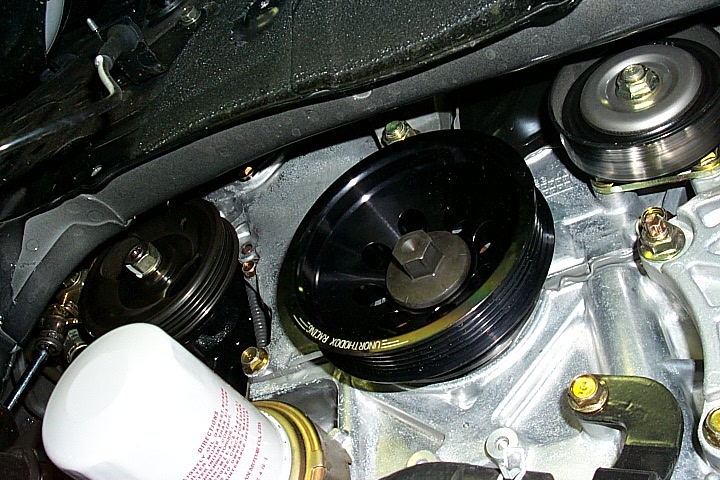
Steps to remove the stock pulley and replace it with the Unorthodox pulley are straightforward. The procedure is the same as the one followed for the UDP on my 1999 Maxima. This photo shows the stock pulley removed.

It was discovered that the serpentine belt (K060408) used for the VQ30 install fit the VQ35 fine, but the power steering belt was a little bit too small, so we replaced it with a Gates K040300.

The only modification required on the Unorthodox Pulley for it to fit the VQ35 was the removal of the timing ring. (Nissan removed the timing ring on the stock pulley as well). Performance gains will be measured again on the dynojet several weeks after the install. Check here for results!

Here are the Dynojet results after the UDP install, superimposed over the stock graph, Run #1:

Max Power = 208.8 (Increase of 4.45%)
Max Torque= 228.4 (Increase of 4.82%)

Loading

Member Credit: Greg

There has been some very uninformed and incorrect information going around the electronic Maxima community regarding use of the Unorthodox Racing Underdrive Pulley.  Some of the unsubstantiated comments I have heard are:

“It will blow your crankshaft”
“It will imbalance your motor”
“It will make your idle rough”

All of these accusations are totally and completely false, and unfortunately not one of them has come from a Maxima owner who has any experience with the Unorthodox UDP on the Maxima!!   Interestingly enough, everyone who has the pulley installed speaks very highly of it and has never had the slightest problem – either a blown crankshaft or rough idle.

Some have claimed that the Unorthodox UDP eliminates some non-existent “rubber ring” on the stock pulley.  This is incorrect!  The rubber ring people are referring to is the crankshaft oil seal, which is a separate part and must be replaced when changing the pulley.  Those who do not change this part, or worse – leave it out after changing their pulley will definitely have major problems!!

Secondly I have heard others mistakenly associate the incorrect assumption regarding the crankshaft oil seal with the equally incorrect assumption that this “ring” (really the oil seal) is some sort of harmonic balancer, and removing it will cause your crankshaft to explode!!!  It does not seem to matter how much factual information is presented, many continue to insist that the Maxima’s factory crank pulley is also a “harmonic damper”.  This is simply not true at all.  A direct quote from the Unorthodox Racing FAQ on their web site:

Our pulleys are so well balanced that when owners call us about how happy they are with the product they always mention their motor feeling smoother. Lastly is the misconception that the crank pulleys on these vehicles are harmonic dampers. A harmonic damper is a unit bolted to the crankshaft snout that is completely separate from the belt drive system.  An engine that uses a harmonic damper has the accessory drive crank pulley bolted to it, they are separate pieces that are attached to each other. Balance shafts, which are used by several manufacturers, are specifically designed to eliminate harmonic vibrations. None of the vehicles we manufacture pulleys for have harmonic dampers in the traditional sense.

Those that would discount the Unorthodox Racing FAQ as “company propaganda” should take a close look at the pictures of the stock crankshaft pulley above, and note that there are no rubber rings or other attachments on the pulley – it is one solid piece!!!

I definitely believe that when it comes to aftermarket engine modifications, one should always be very careful and know what he or she is getting themselves into before making a purchase decision.  The decision should be made based on facts and accurate information, not rumor and ignorance about a company or its products.  After well over a year, the UDP continues to be one of my favorite mods.  It delivers extremely smooth quiet power and has never given me the slightest problem or cause for concern.

Step 1 – Remove the stock pulley

This is the hard part. If you can get past this, you’re home free. First jack up the passenger side of the car and remove the front wheel and oil cover. This will expose the crankshaft pulley. You will need to loosen the bolt that holds the pulley to the engine. The bolt was 19 mm on my car. When you try to loosen the bolt, the entire pulley (and all accessories) will rotate counterclockwise – you need to stop this from happening or you will not be able to get the bolt off. With the 5-speed car, all you need to do is have an assistant get in the car, put it in 5th gear and hold the brake pedal. Then you can get under the car, get the 19 mm socket on the crank pulley and YANK for all you’re worth, being careful not to give yourself a hernia (I’ve had two myself). If you have air tools you can get this bolt off easily without having to lock the flywheel (regardless of manual or auto trans), but you will eventually need to lock the flywheel in order to torque the bolt down after the new pulley is on.

If you do not have air tools, and your car is an automatic transmission model like mine, you do need to lock the flywheel in place while the bolt is being loosened. On the ’99 Maxima there is a small access port just to the driver’s side of the huge steel support bar which runs down the middle of the engine underneath the car. The access port has a cover plate which is held in place with two small easily removed bolts. Removing the small bolts will expose the flywheel. We used a piece of hardened steel (a chisel bit) to stick in between the flywheel and the housing cover being very careful not to damage the flywheel teeth. If your car does not have the access port, it will be necessary to remove the starter motor to gain access to the flywheel. If you have the shop manual for the car, the access port is documented in the section on removing the timing chain, and in the section on removing the oil pan. Nissan calls it simply a “rear cover plate”.

It was not necessary to remove the starter on my car, but I do not know if all 4th generation Maximas have this access port. It was clearly put in place by the Nissan engineers with the express purpose of allowing access to the flywheel. Check your vehicle. Anyway – thanks Nissan for putting it there.

Step 2 – Remove the drive belts

Once the pulley bolt is loose, go about the normal procedure for removing both drive belts. To summarize, remove the large belt by loosening the idler pulley bolt and then loosening the upper bolt to raise the idler pulley. Next, lower the power steering pump and remove the smaller belt. This procedure is also outlined very well in the shop manual. This was not easy, even for Shawn, which is why I recommend a pro for this
job. The difficulty is in the placement of the bolts for the power steering pump, which are difficult to reach. Small hands, a universal, and a LIFT make this a lot easier.

Step 3 – Remove the stock crank pulley

Remove the stock crank pulley. My car was almost brand new so the pulley slid right off the spline without the need for a gear puller. If your car is older, the pulley might be a little more stubborn and require the use of a gear pulley. A good gear puller is an invaluable tool anyway and is available for about $25.00 from almost any automotive store or from a Sears hardware store.

Step 4 – Replace the front oil seal

The shop manual recommends replacing the front oil seal any time the crank pulley is removed. This may or may not be overkill, but considering that the rubber oil seal is only $6.50 from a Nissan Dealer (part # 13510-31U00) you might as well do it. Simply stick a flat bladed screwdriver in there and pop the oil seal out. Coat the new oil seal with motor oil and pop/tap it back in place. Real easy.

tep 5 – Install the new pulley

Coat the inside bore of the new pulley with anti-seize compound and then slide it onto the engine. The UDP is keyed so you can only stick it on one way. Snug the bolt down but do not torque it yet. According to Shawn, the primary purpose of the anti-seize compound is to limit the contact of the aluminum pulley with the steel crankshaft spline. Something about dissimilar metals not “liking” each other. One thing I noticed immediately was the weight difference between the stock pulley and the Unorthodox Racing pulley. The stock pulley weighs in at a whopping 5 pounds! I didn’t get a chance to weigh the UDP, so I don’t have a number but I can tell you that it is made from lightweight aluminum and weighs MUCH less than the stock part.

Step 6 – Replace the belts

Since the new pulley is smaller than the stock pulley you will need to get new shorter length belts. You cannot reuse the stock belts. I went to a local US-1 auto parts store and bought the exact belts recommended by Unorthodox. They are Gates belts, numbers K-060408 and K-040292. I tried Pep Boys and Auto Barn, but neither of those stores carried Gates belts. The price of both belts together was $31.44. You can buy the belts from Stillen directly, but their price was $54.00. I recommend getting the belts locally. Follow the factory procedure to put the new belts back on, and tighten them to factory specs. Now you can torque the crank pulley bolt to 140 ft-lbs. Again – follow the same procedures you used earlier to secure the flywheel from rotating. Torquing this bolt properly is very important – USE A GOOD TORQUE WRENCH. The last thing you need is to have your crank pulley come flying off the engine during spirited driving. I also cannot stress enough the importance of belt tension. FOLLOW THE FACTORY MANUAL. For a new compressor belt the deflection should be 3.8-4.1 mm, and the power steering belt should be 6.5-7 mm. If you do not tension these belts properly they will squeak like a stuck pig!!

That’s it. Put the oil cover and flywheel rear cover plate back on, put the passenger wheel back on, torque the lug nuts to 85 ft-lbs and drive away!. I noticed an immediate improvement in low-end torque, which increased over time as the ECU in the Maxima got used to the new pulley. I would estimate that about 75% of the improvement comes right away, with the other 25% coming as the ECU re-adjusts.

Loading

Member Credit: Greg

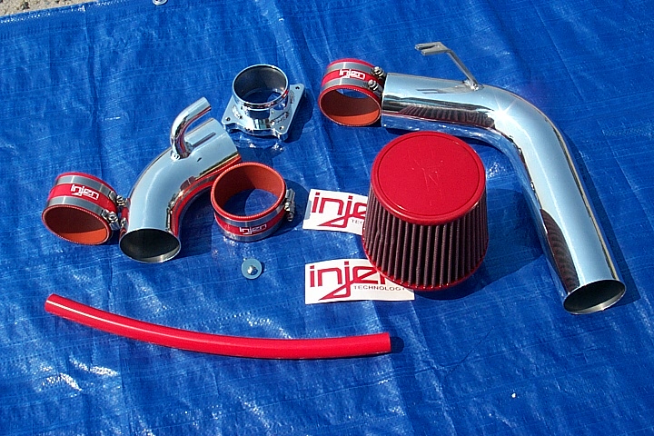
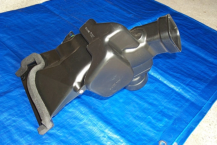
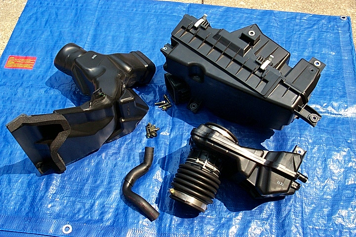
I ordered the Injen Cold-Air Intake from Adventon.Com for the price of $238.56, which included UPS 3-day shipping. If you don’t need it in 3 days, knock $13.75 off that price. I found Adventon a pleasure to deal with and would highly recommend them to anyone interested in this (or any other) intake. Pictured at left are all of the parts that come in the kit. Injen also includes an excellent set of clear instructions. My only complaint is that they are not in color, but that is minor.

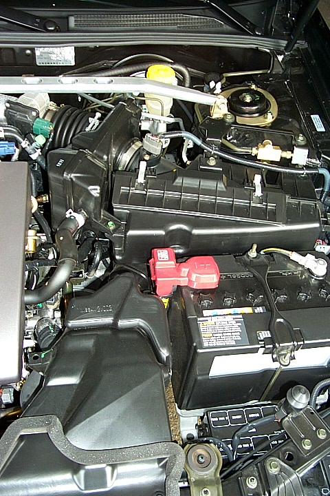
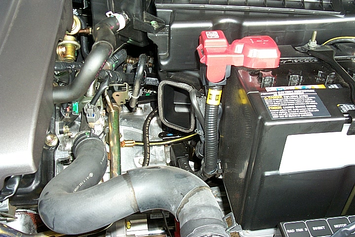
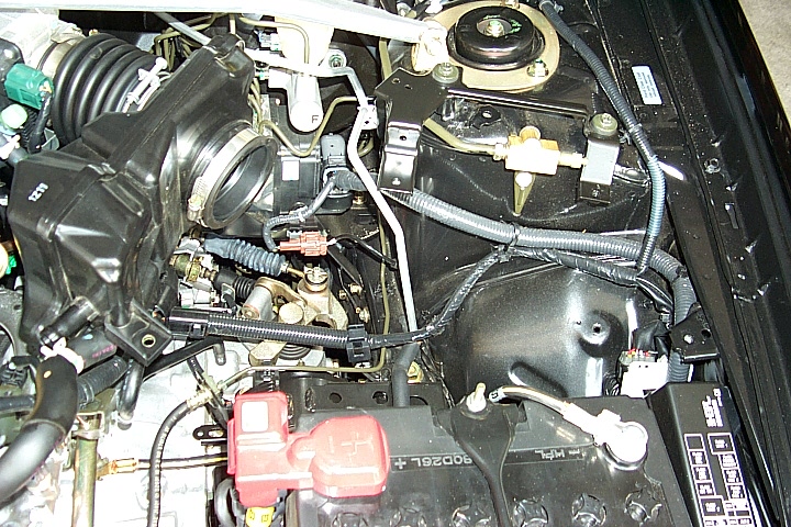
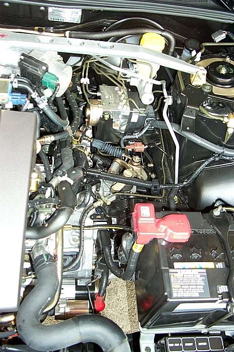
Shows the stock intake plumbing. It’s pretty complicated and has lots of pieces, but it does an outstanding job of completely silencing all intake noise.

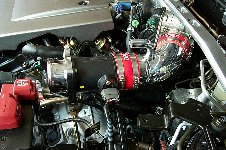
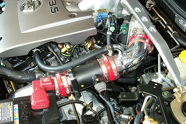
Shows the completed Injen intake installation in the engine bay. Now let’s see what’s involved…

Step 1. Remove the stock intake scoop. 3 screws, a tug and it comes right out.

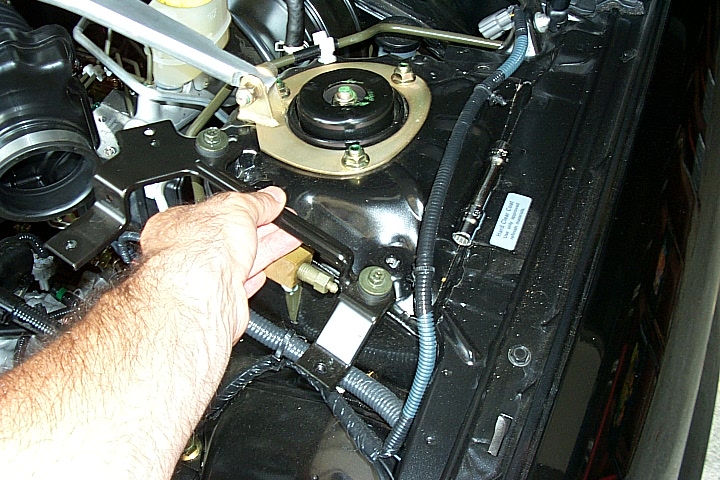
Step 2. I don’t believe all 5th-gen Maximas are exactly the same, but on my car (a 2002) I had to remove this short piece of metal on the driver’s side shock tower in order to lift out the large filter box. I put it right back on after removing the box. 2 screws are all that hold this piece on.

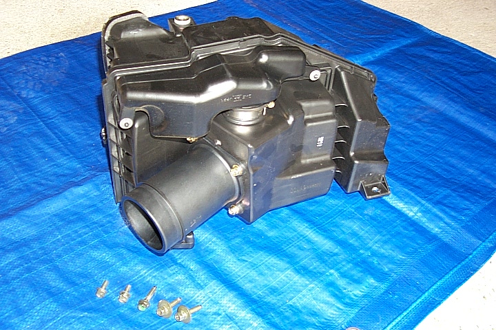
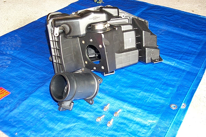
Step 3. 5 machine screws hold the filter box to the chassis, and must be removed in order to lift the box out. The clamp on the other side of the MAF sensor must also be loosened. Note the MAF sensor is still attached to the box and must be removed next.

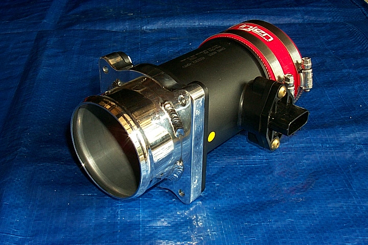
Step 4. Remove the MAF sensor from the filter box and attach the Injen aluminum billet adapter and rubber sealer hose. The combined assembly will be used in the Injen intake tract.

Step 5. The last piece to be removed from the stock intake plumbing is the small intake resonator. This exposes the throttle body and completes the disassembly process.

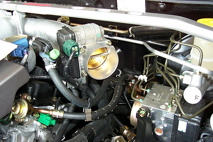
Here is the engine bay with all components of the stock intake tract removed. It is quite amazing how much space is taken up by something as simple as an intake!

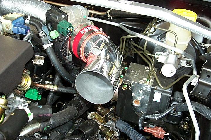
Step 6. Assembly of the Injen intake plumbing is straightforward from this point on. The elbow piece is the first to go on, attached directly to the throttle body. I recommend snugging the clamps but not tightening them all until the end, when the intake is positioned properly.

Step 7. MAF sensor assembly.

Step 8. The last piece to go on is the long filter tube plus filter, which is a little bit tricky to maneuver within the confines of the engine bay. A little patience will get you through. Last step is to reattach the red breather line. The red line seems a little bit incongruous against all of the other black hoses in the engine, and I may replace it with a black one from a local auto parts store. It is a 16-inch long 15mm line, and should not be difficult to find.

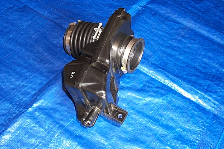
For interest purposes, here are all of the pieces of the stock intake which are removed during the Injen intake installation.

Impressions so far: Fit, finish, fitment, and ease of installation of this intake rank very high in my book. All of the pieces fit the car like they were made by Nissan, which is not always true with aftermarket parts. I like the idea that there is no cutting or drilling involved with this cold-air intake, and the filter is not inaccessible (like in the wheel well). If you want to sell the car, everything can be put back to stock easily.
Since the intake resonator is removed, I had thought this intake would be a lot louder than the Stillen high-flow I had on my ’99 Maxima, but I actually found the opposite to be true – possibly because the filter element is located far away from the passenger compartment, and this is where most of the “whoosh” from the Stillen intake came from.

Low-end power does not seem to be affected at all. Similar to the Stillen intake, the Injen is well-behaved until you stomp on it, and then it sounds, well – “interesting”. Not obnoxious or anything, but it is obvious there is something unusual under the hood. Injen claims 12-13 wheel horsepower increases, which I can neither confirm nor deny, but the butt-dyno can definitely feel the difference this intake makes.

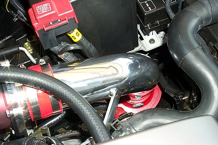
Here are a few more pictures of the completed intake. Note, the breather hose has been changed from red to black, and I secured it with a regular adjustable clamp instead of the Nissan squeeze clamp, which is really too small for the Injen. This shot shows the tubing from the throttle body, through the MAF sensor, and up to the main intake tube.

Here is a view taken from the passenger side of the car, looking to the left and down, showing the location of the filter element.

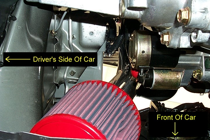
I had to break out the hydraulic jack to get this shot. It was taken from underneath the car looking straight up from the filter to the main intake pipe. The photograph is labeled for orientation purposes. As I was exploring around underneath the car, I realized that fabricating a makeshift air opening out of the existing undercover would not be difficult and would provide a direct flow of air to the intake. I will be working on this as a future project. Coming soon….

Loading

Member Credit: Greg

I might be going out on a limb classifying the changing of your manual transmission fluid as a “performance” modification, but considering how use of this stuff will improve your shifts in both cold and hot weather, the classification might not be that far off. I used Red Line D4 ATF in my 1999 Maxima, and the automatic shifts were much more crisp and smooth, so I decided to give the manual transmission equivalent a try. Nissan recommends gear oil of API grade GL-4 and a viscocity of 75W-90 or 75W-85. Red Line MT-90 meets these specifications.

Transaxle oil capacity for the 6-speed is significantly less (roughly half) that of the prior Maxima’s (1995-2001) 5-speed. You will only need 3 quarts of MT-90, and you will not even be able to use all of the 3rd quart.

Not many tools are needed. A 3/8-inch drive ratchet with a 10mm hex bit is all that is required to remove both the drain and fill plugs, which are identical on the 2002 6-speed transmission.

You also need either a funnel with a long (~3.5 feet) flexible hose, or you can string together anything that will give you the appropriate length. I used a large funnel with a hose extension that allowed me to turn the flow on or off (important if the tip slips out of the fill hole!!).

When replacing the drain and fill plugs, it is a good idea (although not totally necessary) to replace the gaskets. These gaskets do not “crush” like the crankcase oil plug gaskets do, so they can be re-used. Price for each from Nissan was $2.21. You’ll need two. A bit steep…

Here is a blowup from the shop manual. Some of you might notice that this transmission looks quite differently than the 5-speed in earlier 4th and 5th-generation Maximas.


This photo (and the one below) should look like the drawing (above). Photo at left was taken from near the left-front wheel, shooting towards the passenger side of the car. The tranny fluid drain hole is visible in the lower right corner of the picture.

Here is the fill hole. Contrary to what some have done, it is not necessary to jack the car up or put it on ramps to do this job. In fact, I do not recommend raising the car, as all of the fluid will not drain out. I put an old rug on the garage floor and did everything lying on my back – it was not difficult at all – you just need good lighting.

Transax-FillHole.jpg (720×480)

Here is another image from the shop manual, with highlights. After draining/refilling the transmission fluid, you should replace both crush gaskets before putting the plugs back in.

Here is the drain (or fill) plug removed.

It only takes 10-15 minutes for all of the fluid to drain out. The 2002 6-speed transmission will give up roughly 2.5 quarts of very brown-looking fluid.

Here is my funnel system, all rigged up. This is actually the most time-consuming part of the whole process. Making sure your setup is good enough so that it will not leak, fall out of the fill hole, or drop down to the floor. I recommend roughly 3-3.5 feet of hose. You fill the tranny until oil pours back out the fill hole. It should take roughly 2.5 quarts. Note, this is half the capacity of prior Maxima manual transmissions.
After performing this simple change, I noticed that all shifts (especially 2nd-3rd, for some reason) seemed much smoother, and engagement was crisp and positive. An extremely worthwhile investment.

Loading

Member Credit: QNO_A32

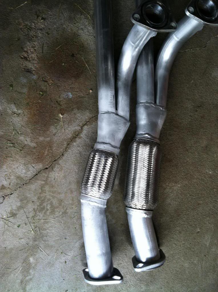
I installed the Warpspeed Y-Pipe today in my driveway. It is a nice piece and im happy with it. It came with all hardware that you need, and even comes with a nice hanger as well. Took me about 1 hour using hand tools.

Things you will need:
Floor jack
Jackstands
1/2″ ratchet
14mm deep impact socket
14mm shallow impact socket
12mm impact socket
22mm wrench
Penetrating oil
1/2″ swivel
1/2″ impact extention

Here is the hanger that came with the y pipe it uses factory mounting points and works very well. It also came with two new cat to y pipe bolts and nuts and gasket.

Here is where the rear downpipe meets the manifold. take out the O2 sensor to give a little more room. The swivel must be used back here at least on two of these nuts. I used the short socket for one and the long one for the other.

There’s no need to show the front it looks just like the rear but is easier to do. same thing…remove 02 sensor and loosen the 3 nuts. Once you take both O2 sensors out and the 6 nuts for the headers you just have to undo the cat to y pipe bolts. My exhaust is new so this wasn’t a problem for me but others might have trouble with rust. After everything is unbolted there are still two 12mm bolts holding the y pipe up…remove these and drop the pipe out.

Putting the aftermarket pipe is much easier you have more room to work with. install the crush gaskets and get the down-pipes on the studs and hand tighten all 6 nuts. put the new gasket for the cat and hand tightened the two bolts. than install the new hanger and tighten it down. Tighten down the 6 nuts but don’t crank them down or they will snap. than tighten the y pipe to the cat and you done. start it up and check for leaks.

I’m OK with the way mine sounds i have a 2.5″ test pipe and a 2.5″ crush bent cat back to a 5.5 gen muffler. The added power is nice too. thanks for reading and I’m sure i forgot something but i hope some people will chime in. THANKS

Loading

Member Credit: SrgScott

Hey guys, I had an oil leak in my upper oil pan, so decided to give you a write-up on how to remove it! I’m going to assume everyone knows how to apply liquid gasket and seals, so I will be leaving that part out. So, if you ever have to remove your upper oil pan, whether its for a simple leak, or your replacing your rear main seal (the “correct” way) then I hope this helps!

I should also warn you. The first time I did this it took me just over 7 hours. But, this being my third time, it took me 5 hours. So be ready to spend the day under your car. I know it will take each person different amounts of time depending on experience. But this just gives you an idea.

Also, I suggest you clean up your engine and engine bay really well while you are in there. I used berrymans B12 carb and throttle body cleaner. The stuff is insane. But be careful to dry it off painted surfaces, just in case

Tools needed:
1/4″ Ratchet
Extension
Breaker Bar
Universal Joint (Swivel Head)
10mm Socket
12mm Socket (Shallow & Deep)
14mm Socket (Shallow & Deep)
17mm Socket
13mm Wrench
17mm Wrench
Gasket Scraper
Flat Head Screwdriver
Rubber Mallet (May not be needed, I did need one)

Now on to the process!

Step 1: Remove the ground cable from your battery, safety first!

Step 2: Drain Engine oil (Mine was a 13mm Plug, however, yours may be 14mm or another, just try wrenches till you find the right one for you), and remove oil filter.

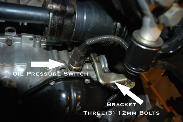
Step 3: Remove both CKPS sensors, three(3) 10mm bolts total, and the Oil pressure sensor(along with the little bracket that holds the wires, three(3), 12mm bolts)

Step 4: Remove the ten(10), 10mm bolts that hold up the steel oil pan. Picture only shows five, but you get the idea.

Step 5: Remove the oil strainer, two(2), 12mm bolts

Step 6: Remove the Y-Pipe, eight(8), 12mm nuts(Aparently on some other Maxs or I30s the 6 nuts at the manifold may be 14mm, again, just try them till you get your correct size). You will need your extension, universal joint, and both shallow and deep 12mm sockets here. Also, you may need some liquid wrench for the nuts, as they may be rusted on, be gentle yet firm and TAKE YOUR TIME, you don’t want to break a stud off. (Sorry, I don’t have a photo for this step, but if you need one let me know and I will get one for you!)

Step 7: Place a SUITABLEfloor jack on a SAFE location on the trans to support it for the next step. In the photo is where I placed my floor jack. You could also use an engine hoist if you want.

Step 8: Remove the eight(8) center beam bolts

Step 9: Remove your drive belt. 14mm deep socket and an extension is what I use.

Step 10: Remove the A/C Compressor, and its brackets. Six(6), 14mm bolts, and two(2) 12mm bolts.

After removing the compressor, I place it on an extra jack stand so it is not just hanging there adding stress to the lines.

Step 11: Remove the cover plate, its black and literally covers a hole that lets you inspect the timing ring. Two(2), 10mm bolts. Sorry it’s not in the photo, but you get the idea.

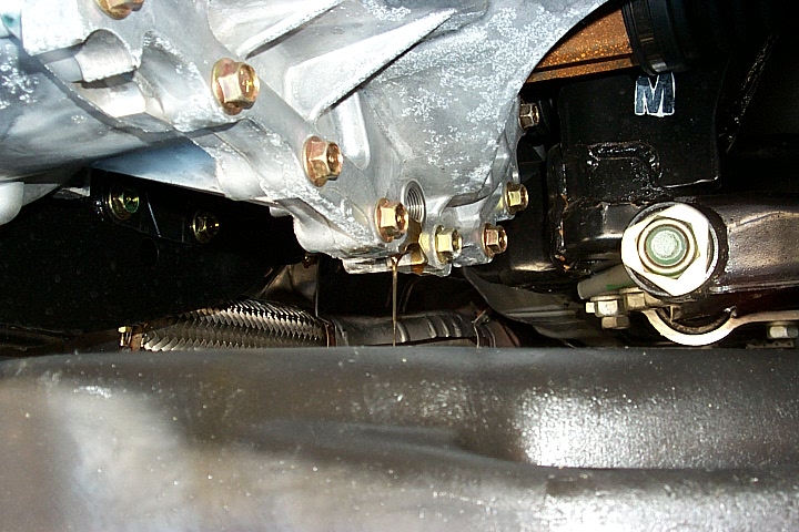
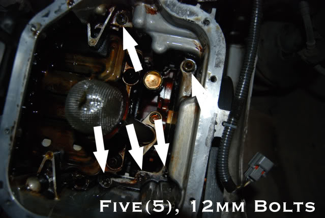
Step 12: Remove the Upper oil pan. Twelve(12), 12mm bolts(Five are inside where the oil strainer was, see photo), and then remove the four(4), 14mm tranny bolts(see photo). I’m sorry I dont have a photo of all twelve bolts the hold it up there, its just a little difficult to get a D80 under there. If you need me to get some photos of the bolts for you let me know and I’ll do my best.

The upper pan won’t come out too easily. Just be patient with it, there are a few spot that have a slight indention where you can place a flat head screw driver(or the recommended tool the dealer uses) to pry it off. Just take your time and it will be off soon.

And here is the upper oil pan off of your car, congrats! I’m so proud of you…..

See the two little o-rings there? If they are still in good condition (as mine were) just clean them up and use them again, otherwise, replace them (dealer part?). Look at the bottom of your engine, you should see where they go, I just put a tiny bit of liquid gasket on them to hold them in place while I installed the upper oil pan. Be sure to scrape all of the old gasket out of those little crevasses, so that your new liquid gasket will work as intended!

And here is the view from the bottom of your engine, not the best photo, but you get the point.

Loading

Member Credit: marktab

Hi All — thanks for the other posts on maxima.org on EGR tube cleaning. I spent several hours cleaning mine, and decided to take comprehensive pictures. Enjoy!

Why are you posting so many pictures and information since this topic is often on maxima.org?

The EGR Tube cleaning took me hours to finish. Also, this cleaning job does not appear in my generic Nissan service manual, nor is it in the official Nissan service manual. People who repair cars a lot or who are advanced will NOT need this much detail (and there are many advanced or professional-level people on this forum). I consider this project as an intermediate-level service task, and the directions can help you or help someone you might pay to do it for you.

Do you recommend removing from the top or the bottom?

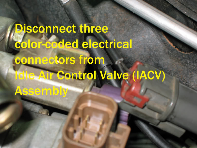
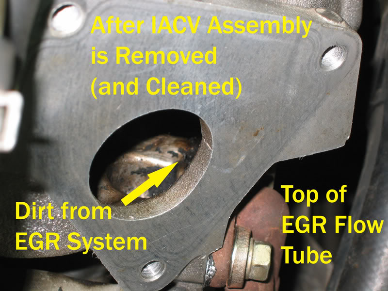
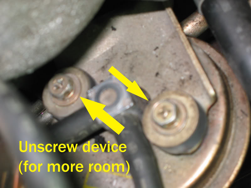
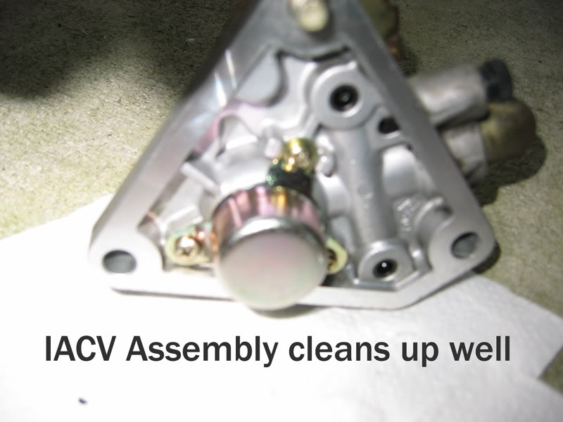
Some have had success removing the tube from the bottom (under the car). However, I believe a better solution is to remove the IACV assembly so that you can clean it. Also, the hole where the IACV assembly goes provides a way to scrape and clean the area where the EGR Tube empties into the main air flow chamber. I did NOT remove the intake manifold.

Do I need to purchase replacement gaskets?

I did not, and I made sure that I was not soaking my original gaskets with the cleaning solvent. If you do destroy yours, you could probably cut your own new ones from gasket material designed for exhaust pipes.

Did you replace your EGR flow tube?

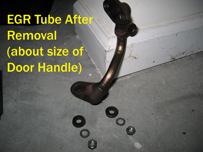
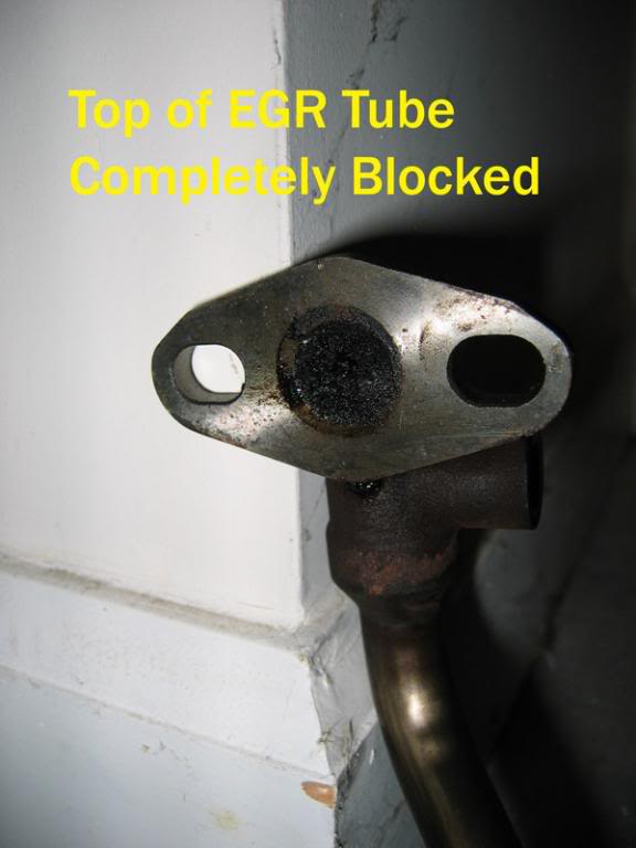
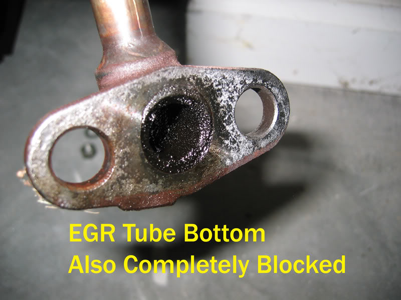
Someone mentioned that they bought a replacement tube. I think it’s sufficient to clean the tube you have unless you have some reason to get a new one (say if it rusted or cracked). Even if you buy a replacement tube, you will still need to clean the sensor off, and also the ports where the EGR tube connects to the car. I found more carbon at the top end, and I believe there was more there because of the sharp airflow angle. The IACV assembly also can be cleaned, and the IACV assembly port allows for cleaning the main airflow chamber.

How quickly can the job be completed?

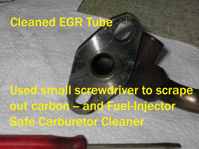
We can compare how long it takes to remove the EGR tube from the vehicle. Some say they can remove it in minutes, and I believe experienced people can do it that quickly. However, the entire time is affected by how much cleaning the tube needs, and how much time you need to clean the connection port areas and the IACV assembly. In cleaning blockage, you need to at least scrape enough out to allow airflow again, and at best, you can clean these areas back to the original bare metal surface. If someone claims to do this whole job quickly, I would wonder how much time and care they put into the cleaning. Poor cleaning will shorten the time until the next required cleaning.

How often should the EGR flow tube be cleaned?

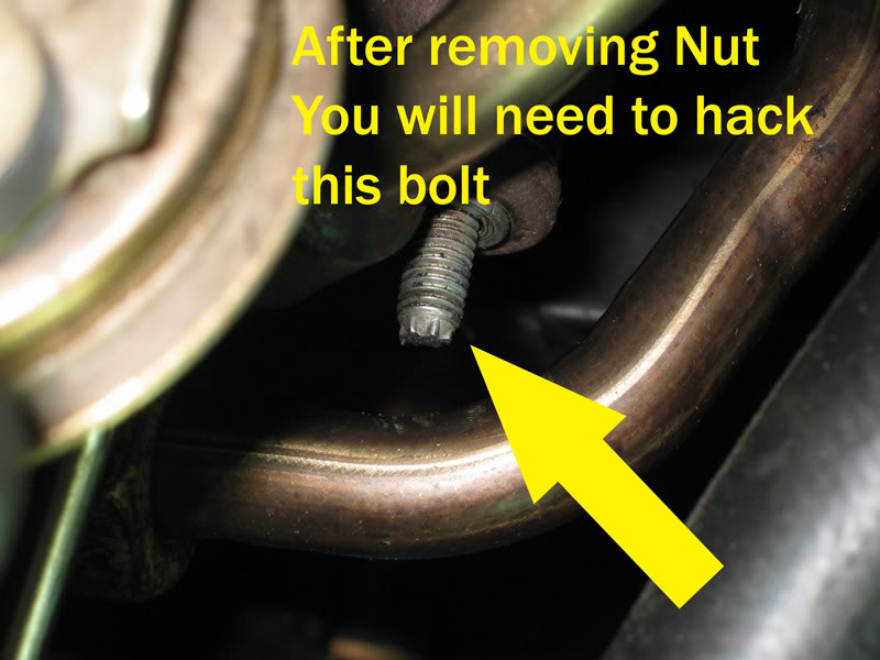
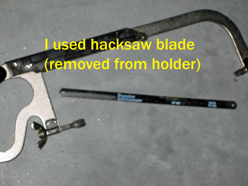
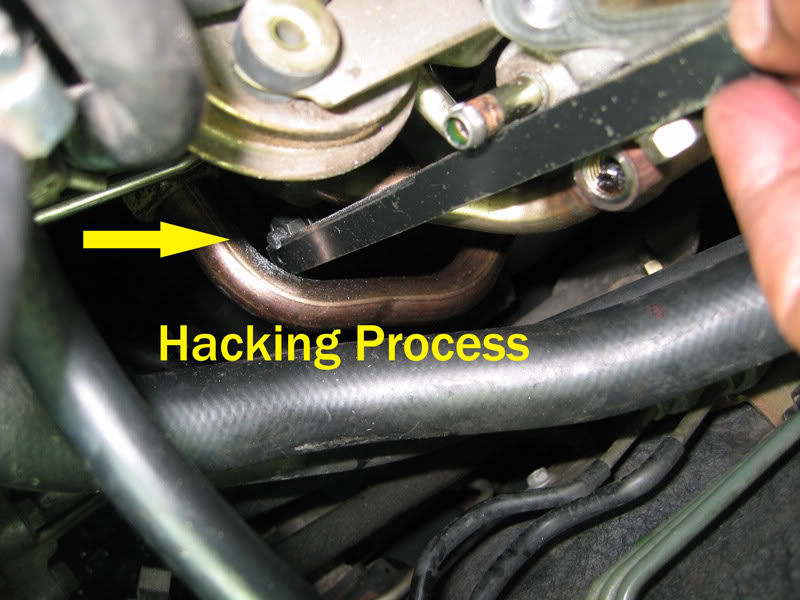
My tube was cleaned for the first time at 111K miles. It was already blocked and throwing the P0400 (same as P400) code (which is one code which will turn on the yellow engine light on the dashboard). I believe the answer varies on your oil choice, driving habits, and typical use (meaning city or highway driving). I believe that 100K is too long to wait. Now that my bottom connection nut has been hacked, cleaning it in the future will take less time.

Did the problem prevent passing emissions?

I have passed Georgia emissions every year since I got the car in 2000 (with 22K miles). This year (in January 2009), I had to replace the faulty gas cap. I do not know if this issue has been preventing people from passing emissions.

Do you recommend blowing the EGR carbon through the engine with seafoam or other solvents?

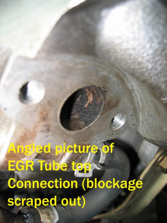
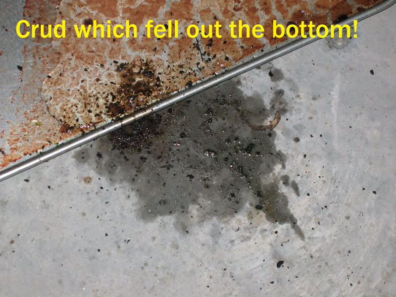
I believe that solution is NOT a good idea for this application. It is better to carefully scrape and remove the carbon deposits with fuel-injector safe carburetor cleaner. You can also spray this cleaner into the port where the IACV assembly goes. I would NOT expose my Maxima to excess oxygen or fuel, and expect it to run well, so I would NOT expect that putting extra carbon into the engine is a good idea. The carbon left by the EGR is not just black deposits on the metal wall, but thick tough carbon that I needed to carefully scrape out (mostly with a small screwdriver head).

What is the difference between cleaning the EGR flow tube and leaving it alone?

In my case, I simultaneously received the P0325 and P0400 codes together. The P0325 (or P325) code means change the knock sensor, and I was able to do that with directions from the maxima.org forum (and a replacement part from Ebay at about US$28, bought mine from the Ebay seller “abcmarts”). Changing the knock sensor alone improved my acceleration, and also improved engine starting (the engine used to require more cranking). Changing the EGR Tube has just about removed all pinging, and also improved acceleration (more). I track MPG, and have NOT seen a difference. Also, if you do NOT clean the tube, your engine will probably run (if that is your goal), but cleaning it helps restore toward the original engine performance (and probably extend engine life, even though no one could probably prove that point in all cases).

Do you believe blocking the EGR system is a good idea for Maxima fourth generation?

I do not, because of all the systems which connect into the EGR valve. You can study these connections in the official Nissan service manual (check eBay if you want to buy one). If you happen to be an automotive engineer and could prove to me comparable or superior performance using some workaround, I would like to hear about it.

Do you believe the EGR tube could be redesigned?

I believe the tube could be redesigned to allow for smoother air flow. As it is, the sensor comes into the tube at a right angle to the airflow (the sensor looks like a thermistor, a device to measure heat, and therefore a proxy for air flow). My EGR tube was most blocked at the top connection side, where the tube bends at about 90 degrees, and then goes into the main airflow chamber (and that part has a sharp bend too). None of us needs advanced automotive training to know that these sharp corners do not help airflow, and certainly not airflow filled with carbon particles. I believe a better air flow tube (and wider diameter) would be better. I have a theory that a better-designed tube would need to be cleaned less. The spacing, however, is tight, but maybe someone with good welding skills might want to fabricate and test a replacement.
So, has the light stayed off?

Yes, the light has stayed off for the last 500 miles. My story started with two engine codes, and in my case, I replaced the knock sensor first. The P0400 (same as P400) came back after less than 30 miles, and after a few weeks, I had a weekend where I decided to take on the EGR tube cleaning project.

Hopefully, this information will help you tackle the job 

Loading