Credit: Craig F.


![]()


")
Community Member Credit: twiggy144 / khemraj1999
The rear O2 sensor (downstream of the cat) failed. I had both codes 0512 and then 0912. This lights up the SES warning lamp, but the ECM does not use any other signal from the rear O2 sensor as input to manage the fuel and ignition system in a closed-loop operation. The only purpose of the rear O2 sensor is to monitor the function of the catalyst. So I didn’t care much about having a functioning rear O2 sensor. I wanted a creative solution to turn off the SES lamp. A search on eBay resulted in an “O2 sensor simulator”.
I ordered one unit and installed it. My installation also included 2 additional 25 ohms resistors rated for 15 Watt load to simulate the O2 heater function. The ECM also monitors the heater function of the O2 sensor. So I had to take care of that error code as well to have the ECM turn off the SES lamp. I tapped in the 2 resistors in series in place of the heater wires. As an alternate to resistors, I think a simple 12V 3Watt automotive bulb ( No 194) could have simulated the heater function of the O2 sensor.
The whole installation went smooth, and the ECM switched off the SES lamp. I recommend very much the DualO2Sim. It costs much less than a genuine rear O2 sensor. Please remember this simulator works only for the rear (post catalyst) O2 sensor.
The simulator is offered at $30. A genuine O2 sensor costs at least $60. I can make a write-up. I will post it later.
Wanted to share my experience with all.
The rear O2 sensor has 4 wires (on my 1998 Maxima).
Cut all 4 wires of the O2 sensor. Cut the wires close to the bad O2 sensor. That will give you some good wire length after the connector located under the driver’s seat. (On my 1998 Maxima the connector is located under the driver’s seat. This is where the O2 sensor wires emerge from under the car through a rubber grommet). Leave the bad O2 sensor in the exhaust pipe.
The sensor simulator also has 4 wires:
Use a voltmeter to identify which of the white wires above (3- or 4- ) is the +12V feed. The voltmeter will show a +12V signal with wire 3-. Connect this wire with wire a-.
Connect wire 1- with wire c- or d-. (My car only had one O2 sensor ). Leave the other purple wire unconnected if you have only one rear O2 sensor.
That will take care of ECM code 0512 Downstream oxygen sensor high voltage fault.
In my case, I also had to simulate a functioning O2 sensor heater. I used 2 x 25 ohms resistors (rated for 20 watts each) and connected in series them between wires 3 and 4. Polarity is not important for these. Under 12 V these should dissipate 1.5 Watt each, with 0.24 amps running through them. Be careful where you locate these because they get hot. Not burning hot, but hot. I tied these down under the driver’s seat. I estimated this area had enough open air to dissipate the heat. That took care of ECM code 0902 (Downstream oxygen sensor heater or circuit fault).
I have not tried but I think a simple 3Watt automotive bulb (No. 194 for example) connected between wires 3 and 4 will do the job of fooling the error code 0902.
I found the O2 sensor simulator on ebay.com Look for “O2 sensor simulator”. The supplier, Baker electronics, includes detailed electrical schematics for installation. This simulator will not detect a malfunctioning catalyst. Therefore check with your local regulations for compliance with such an installation on your car.
Thought I’d revive an old thread with some pics to help others with an o2 sim install on my 1997 Maxima. I followed twiggy144’s wire codes and o2simulator.com’s installations codes.
I used a sharp knife to slice through the plastic on the wires (DONT CUT). The o2 sensor wires are hard to work with, so I sliced the harness wire. I also left the o2 sensor in to simulate the heater signal but I cut the Sensor’s signal wire (black).
So following twiggy’s instructions:
If u need to get rid of the sim..just pull wires out and tape up the slice. (no cuts involved..except the cut from the o2 sensor signal wire..my sensor was failing so I didn’t care.


![]()
")
Community Member Credit: CS_AR
NOTE: This thread covers remedying the timing chain rattle on 1998 and 1995 model VQ30DE engines. There are differences between those engine years that require a different approach.
If you have a 96-99 model VQ30DE, a new tensioner and gasket can be installed without removing the timing cover and replacing the guide. The tensioner can be accessed via the access panel door on the lower left side of the timing cover using a 10mm socket wrench.
Only the 95 model engine required timing cover removal to replace the guide with the updated version.
Today I performed a Timing Chain Tensioner transplant from a 99 model I30 to the 98 Maxima. The 98 Maxima had the typical morning timing chain clatter noise that comes from a worn tensioner piston inner seal and leaking valves.
The 99 I30 received a new Tensioner and Gasket sometime in 2012. This used tensioner has approximately 40,000 miles. However, this old tensioner has a gasket. I will find the gasket part number and report back more information on how to perform a quick tensioner transplant.
Meanwhile, the 98 Maxima appears to be getting along very well with the replacement tensioner. The engine runs smoothly and quietly now. Hopefully, when I start it at 5 AM tomorrow morning, the usual clatter will be gone.
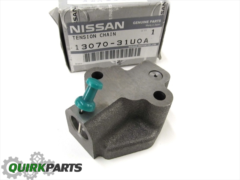
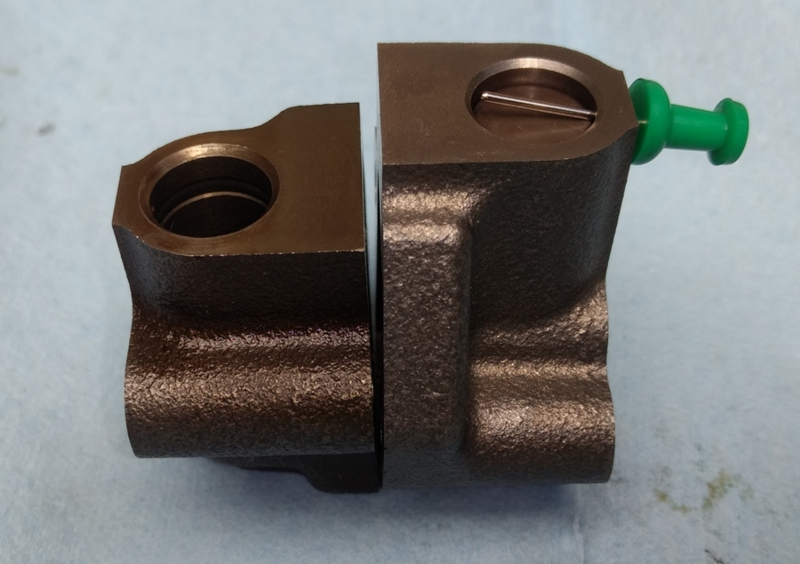
Here’s a picture of the replacement tensioner with a gasket on the left with a regular OEM tensioner from a 97 model SE “junkyard vehicle” on the right.
The results are almost unbelievable. After sitting all night, there was no morning clatter or valve train noise today at 6 AM. This must be how it sounded when it was new.
—————————————————————————————-
Note that I just ordered a tensioner for a 95 model with two gaskets and four bolts from CourtesyParts for the 99 models that is running a 95 model engine. The 95 models use a different tensioner.
The Tensioner I ordered for the 95 model engine is 13091-31U26 for $83.84 at CourtesyParts. The only picture I see of this part contains a guide and the tensioner. If that tensioner requires a new guide, then I’m stuck with removing the timing cover. I need to see how this 95 part is going to work before I can recommend it.
Here’s a picture below for engines built from 1/96 +.
For an I30, I see OIP has the part listed for $61.62.
This tensioner looks like the ones I’ve pulled from a 97, 98, and 99 model engine.
Somehow I think the gasket seals the drain vent to hold oil inside the chamber for long periods of time to reduce the amount of morning clatter.
—————————————————————————————-
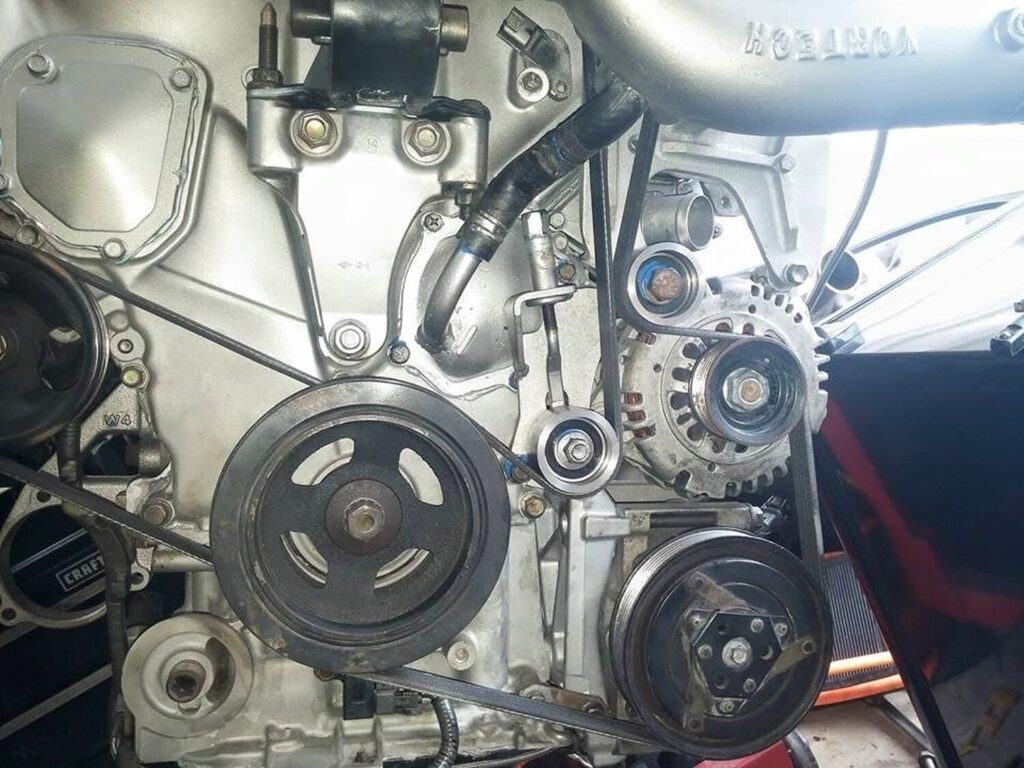
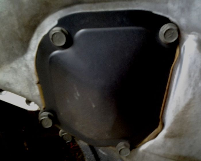
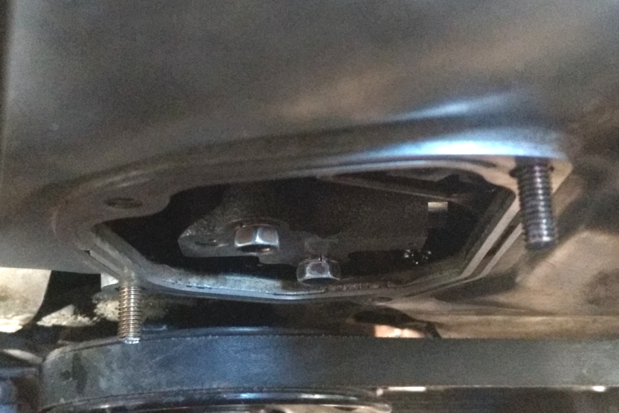
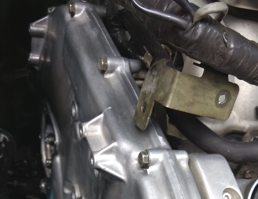
The tensioner sits behind this timing cover access panel. The access panel is held in place with four 10mm bolts.
Note: ALL bolts associated with timing chain tensioner replacement are 10mm.
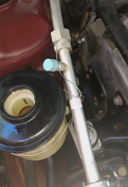
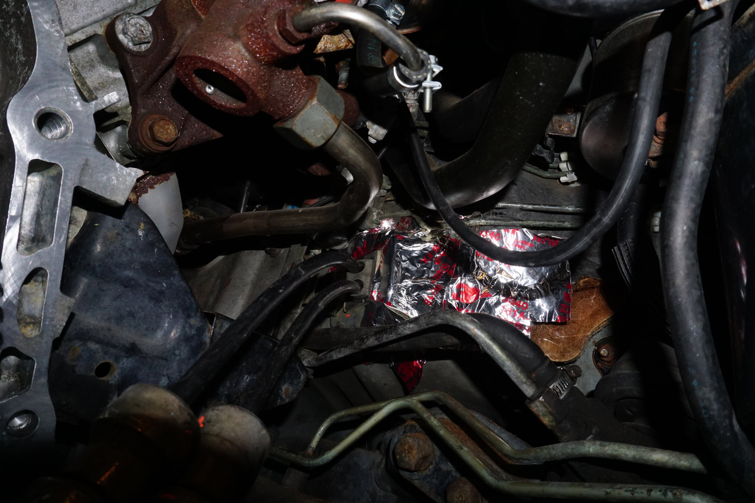
Remove the Power Steering return hose from the reservoir and loosen the A/C line bracket. The idea is to get the PS hose and A/C line out of the way to provide more room for working with the tensioner.
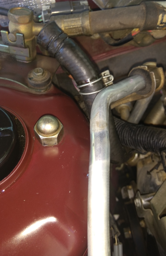
Mechanics wire came in handy to secure the A/C line to the PS fluid reservoir. You can see the tensioner cover in the lower right center of this picture.
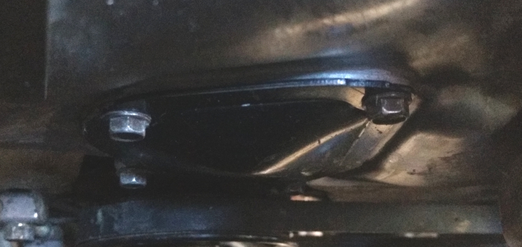
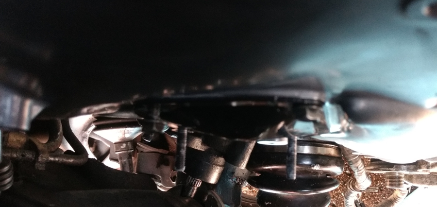
When the tensioner access panel has been removed, you can see the tensioner and the two 10mm bolts that hold it to the engine.
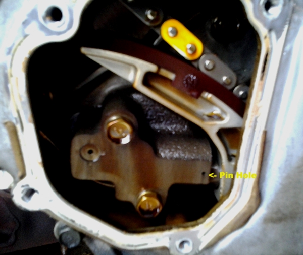
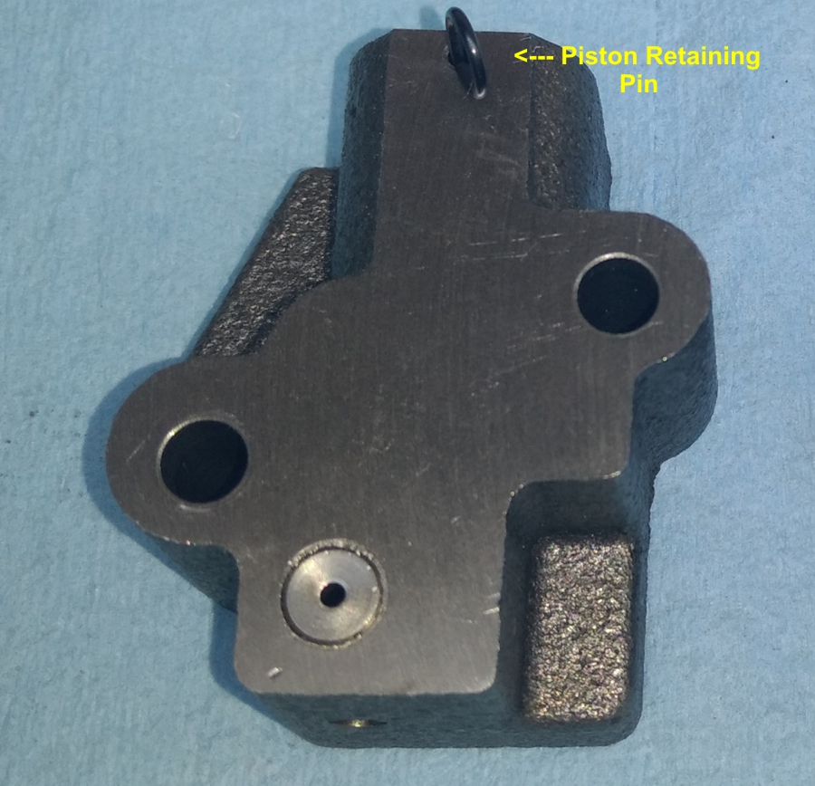
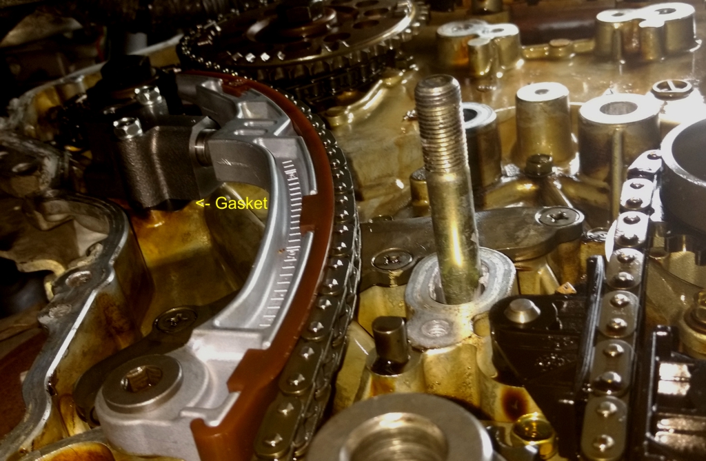
A close-up of the tensioner shows the piston is held in position for installation by the retaining pin. I used some mechanics wire to make a pin for an old tensioner that kept for example purposes.
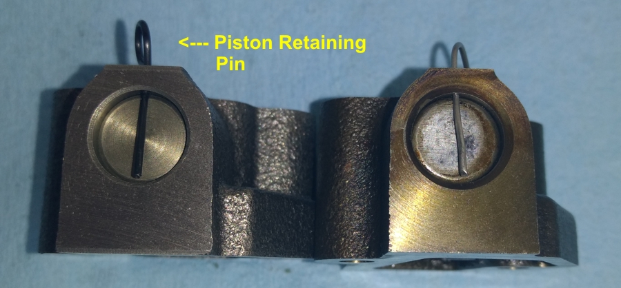
Here’s another picture of the retaining pin. The pin must be left in the tensioner until after it has been bolted down. The final step in the installation before closing the access door is to pull the retaining pin.
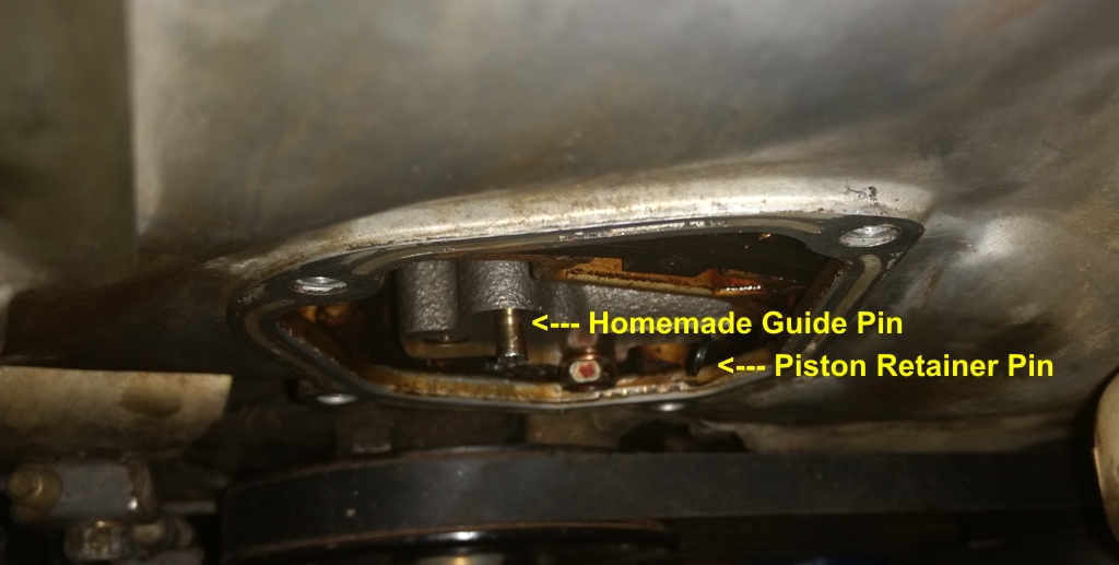
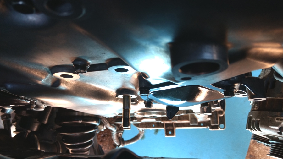
To get the tensioner to align properly over the bolt holes, I cut off the head of an extra bold to make an installation guide pin. I turned the guide pin into the block just enough for me to hang the tensioner on it to get the lower bolt started. Once I had the lower bolt started, I removed the guide pin and installed the upper bolt.
To get the access door properly aligned over the timing cover when the edge was covered in RTV, I used some extra 10mm bolts and made two additional guide pins. Once the access door was in position, I installed two cover bolts, then removed the guide pins and finished installing the remaining two bolts.
Here’s a picture of the access door at the end of the operation. You can see that I used Permatex Ultra Grey RTV.
————–
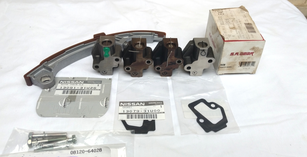
The parts arrived from Courtesy Nissan today. Now that was a Nissan Fast order. It looks like I have everything I need to work on the 99 models (with the 95 engine) this weekend.
So I purchased the tensioner for a 95 model that comes with a guide. I really do not want to use the guide. It was just over 3 years ago that I had the timing cover off of that engine and examined the guides. That engine only had 82,000 miles at the time. I will get a mileage reading this weekend when the car returns. That engine easily has under 150,000 miles.
The new OEM tensioner is on the left. The two tensioners in the middle are from a 97 (salvage yard car) and the 98 models. The tensioner on the right is an SA Gear that I purchased over 3 years ago to go in the 99 models. The guy that did the engine installation and changed the water pump did not install it. While it looks like the OEM, it doesn’t have the same tight/precise feel as the OEM. I can tell the OEM has been built to some very exacting standards. So I don’t know if I will ever use the SA Gear guide.
The gaskets are the right parts exactly. The bolts are correct. I ordered an extra set of bolts and gaskets. I suspect the secret to success here is to always include the OEM gasket with a new tensioner.
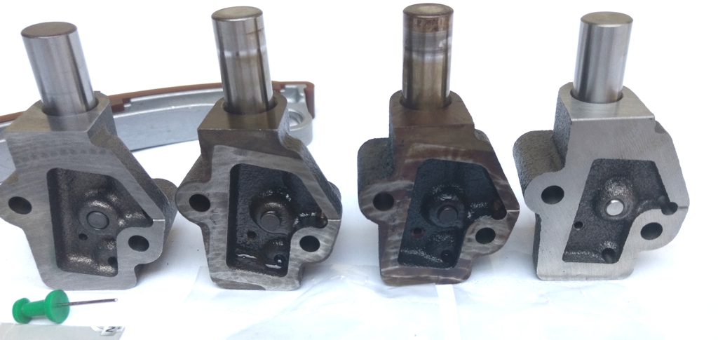
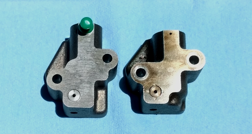
Here’s a close-up of the tensioner back sides below. Again the new OEM is on the left with the SA Gear on the right.
The piston on the new OEM has a very tight and precise fit. There is no piston wobble or shake with the new OEM part. I sure hope I can use it on the 95 model engine.
The SA Gear part (far right) is listed for 95-04 models with both 3.0 and 3.5 engines. I call the SA Gear part a “generic aftermarket” tensioner.
Here’s a video of the 99 Model (95 Engine) before the new tensioner. Yeah it sounds like a diesel in the morning.
The 98 sounded like this before the tensioner upgrade.
Here’s a video of the 98 model after the new tensioner and gasket installation. The 99 model will sound like then when I finish the upgrade. This engine has approximately 237,000 miles.
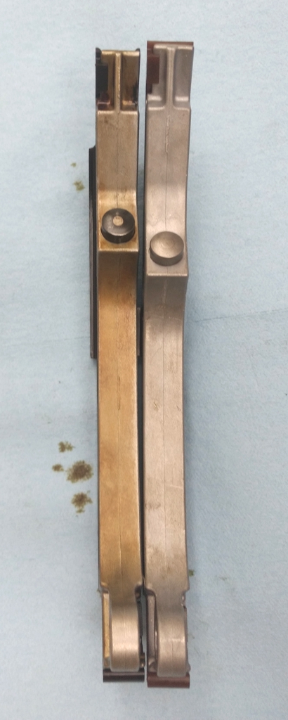
Here’s a picture of the old 95 model tensioner (left) compared to the new (right). I like the new design.
Here’s picture with the new tensioner on the left and the old on the right.
Side-by-side comparison of old 95 model guide compared to the new replacement.
The new tensioner, bolts, gasket, and guide installed.
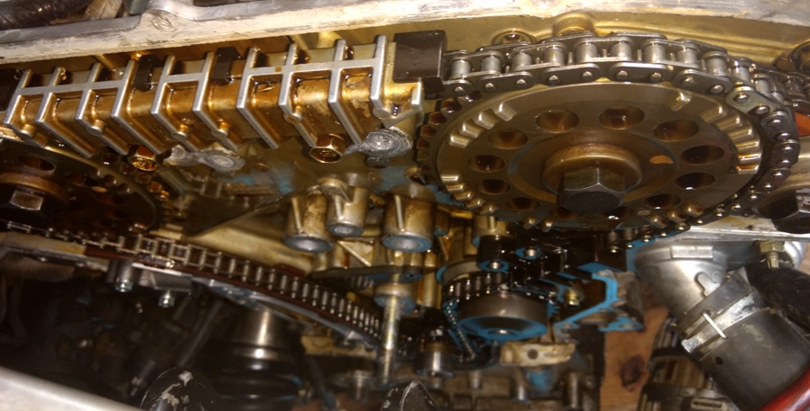
Based on the chain health from the picture below, I think the chain and engine will outlast the rest of the car.
The car (body) now has over 210,000 miles. It looks like a low wear engine.
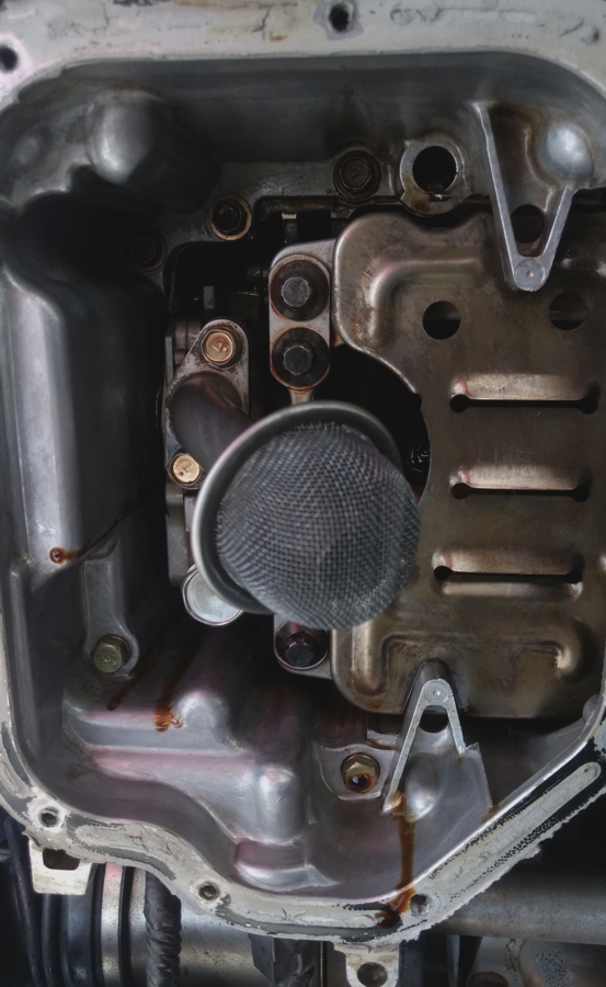
No oil sludge in the upper oil pan parts.
I used the M6 -1.00 x 31 mm automotive stud bolts from Ace Hardware as guide pins to hang the Timing Cover and access doors today. Here’s some pictures from today’s work below.
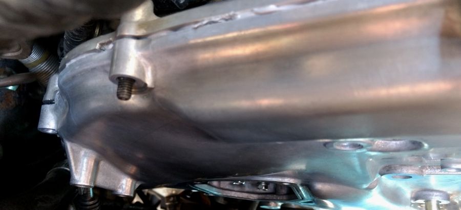
Another picture of using a stud bolt as a guide pin to hang the timing cover.
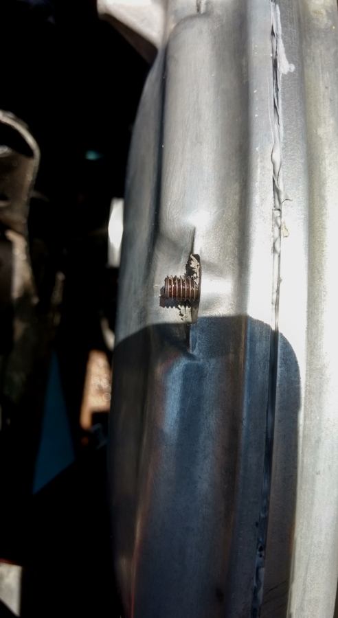
Removed the stud bolts and then used the regular 10 mm TC bolts.
Using stud bolts as guide pins for installing the access doors.
Here’s a picture of the water pump access door after installation. Note that I did not completely remove the alternator or A/C compressor for this operation. I used some wire to suspend the compressor so it would not dangle by the hoses. The alternator is resting on the compressor.
The upper oil pan has been released but not completely removed in this picture. I reinstalled the passenger side engine mount so the engine would be held up by at least two engine mounts before I removed the center cross-member to remove the upper oil pan.
Started the engine this evening. After the expected new tensioner noises that sound like a train clattering down the tracks, all chain and valve system noises stopped. You’ve got to hold the RPM at 2,500 for about 10 minutes after the initial warm up to let the oil circulate through the tensioner system for the system to get quiet. This is a very different running and sounding engine now.
I will make a “cold start” video tomorrow morning and upload it to youtube.
I can’t recall having a 4th gen without some amount of clatter. It almost seems weird.
Here’s the before and after videos from the 99 (95 model engine) so show the difference made by replacing the tensioner, guide, and using the gasket as recommended in the TSB.
Before
After
![]()


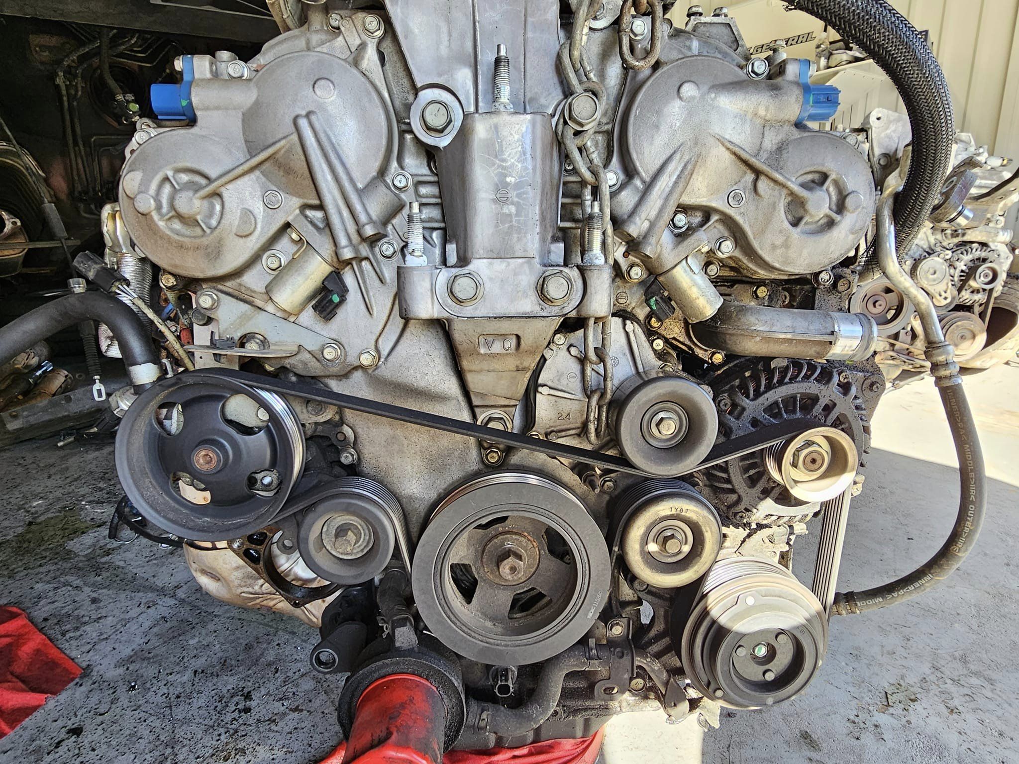
Credit: NISformance
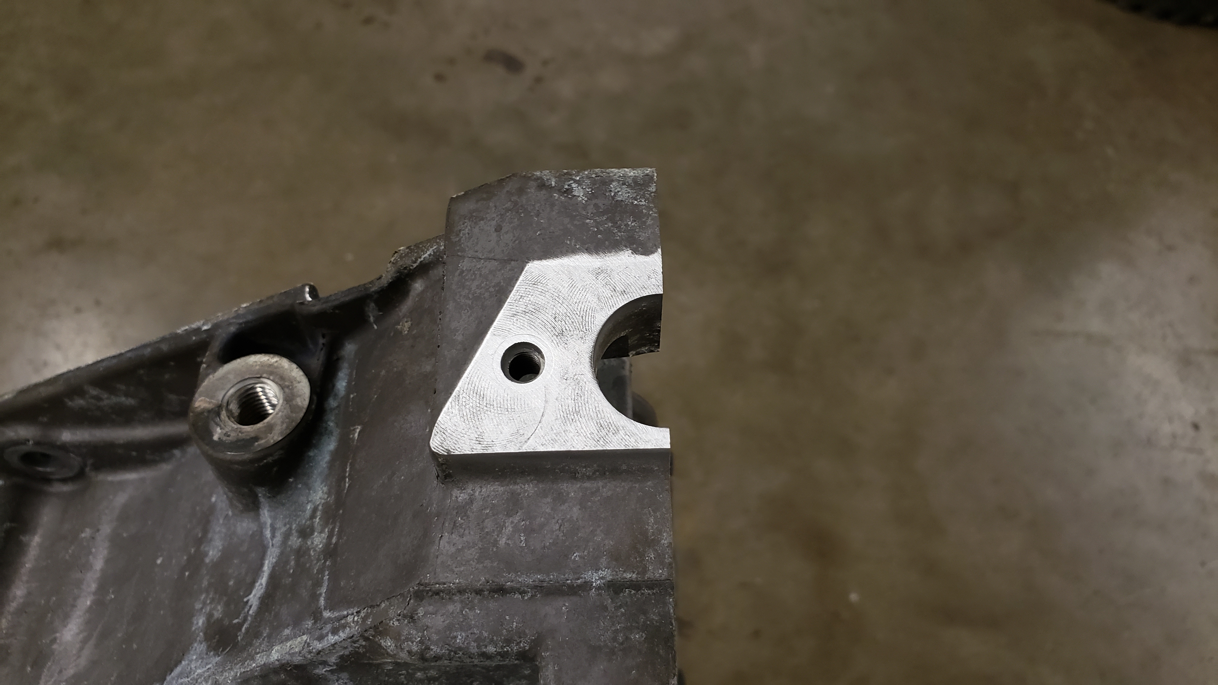
Crankshaft position sensor issue VQ35
Crankshaft position sensor related issue on front wheel drive VQ35 vehicles.
We have found that many FWD VQ vehicles using an aftermarket flywheel often encounter a “hard start” or trouble code “p0335”. Improper distance of sensor to the trigger wheel on the flywheel.
Luckily the fix is relatively easy.
You will need to sand the surface onto which the sensor mounts to the upper oil pan. This will remove build up and put the sensor closer to the trigger wheel, getting a cleaner signal.
In most cases we have seen this when installing an aftermarket flywheel or engine swap.
Before:
After:
![]()
")
Oil Pressure Valve: 15241-43UOA
Part Description: VALVE-OIL PRESSURE REGULATOR
Order Link: https://www.nissanpartsdeal.com/parts/nissan-valve-oil-press~15241-43u0a.html
Price: $10.00
You may get one of the Nissan vehicles listed below in the shop with engine oil accumulated on the engine block below the engine oil cooler area. Inspect the engine, engine oil cooler and the oil cooler gasket for oil leakage. You may use a fluorescent oil dye leak detector to help more easily determine which component is leaking. If the oil is leaking from the oil cooler rubber gasket, replace the rubber gasket using the following manufacturer’s Service Procedure ….
You may get one of the Nissan vehicles listed below in the shop with engine oil accumulated on the engine block below the engine oil cooler area.
Inspect the engine, engine oil cooler and the oil cooler gasket for oil leakage. You may use a fluorescent oil dye leak detector to help more easily determine which component is leaking. If the oil is leaking from the oil cooler rubber gasket, replace the rubber gasket using the following manufacturer’s Service Procedure.
Vehicles:
Service Procedure:
Posting this up just to clarify the relief valve part number and identification, the FSM is pretty vague.The O Ring part number OEM 21304-JA11A or Dorman part 917-036 (Dorman come 3 in a box and can get it at any parts store)
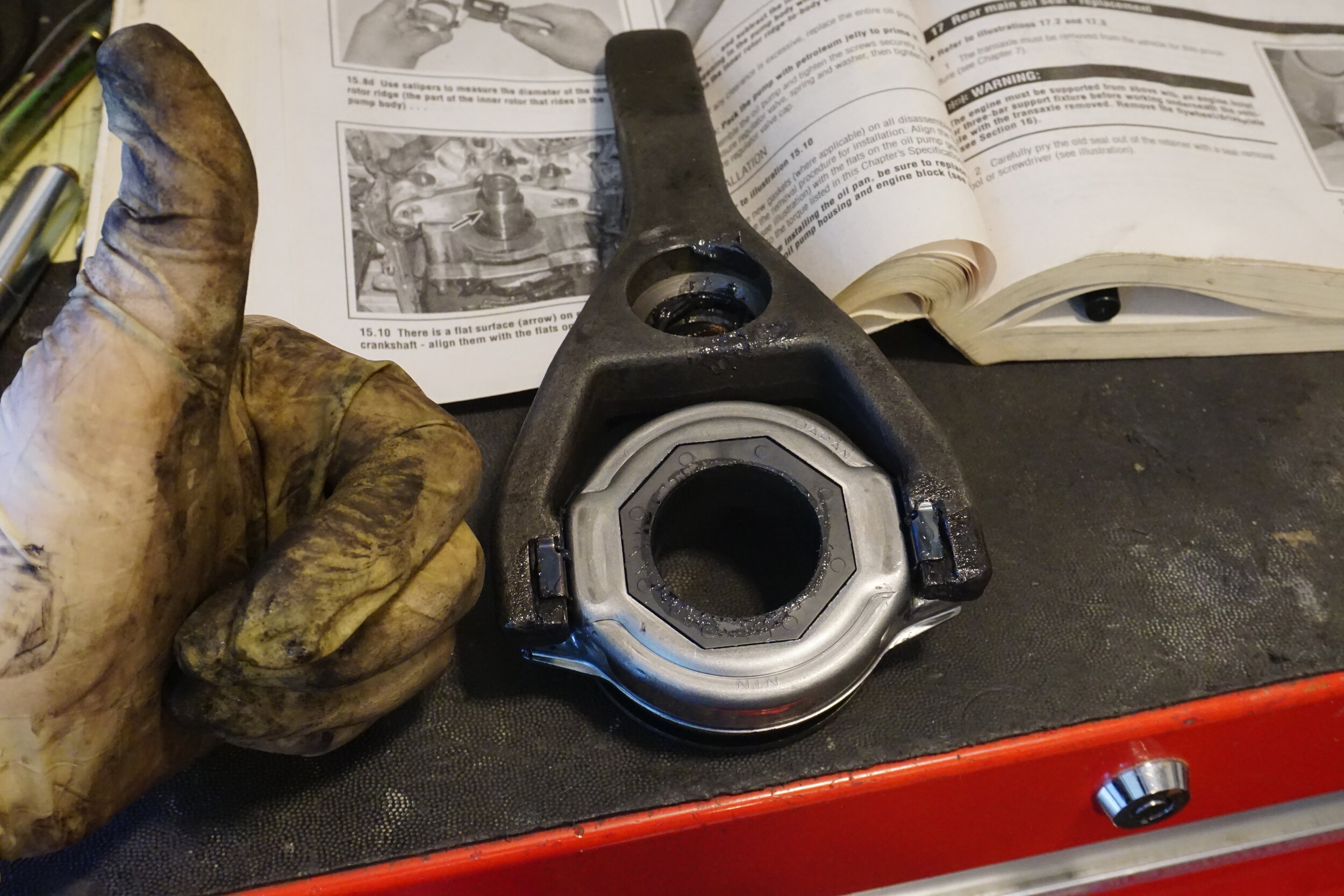
My problem was I also had a broken relief valve? One man show here, pretty tough holding the camera and trying to hold that bearing in place.

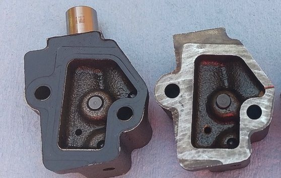
 Part Number for relief valve 15241-43UOA, you can see the broken one on the left I stretched the spring trying to unseat it. You can also see half of the ridge that retains the spring and ball bearing which cracked off. Over tightening the oil filter, metal fatigue(200K) ? It comes assembled in the new relief valve.
—
Just wanted to thank you for posting this fix for the oil cooler on a G35. The part numbers were a huge help as it is often not available and you waist lots of time trying to get them. Removing the oil pressure relief valve required some thinking in order not to scratch the mating surfaces of the oil cooler itself.
I found a bolt with course threads that would actually start threading itself inside the ball bearing side of the valve. Once I had made about 2 turns of the bolt and knew it was securely inside the valve, I place a crescent wrench behind the head of the bolt and closed the jaws of the crescent wrench. I gave the wrench a few taps and the valve came out very easily and without and damage to the surface of the oil cooler.
I aligned the new valve correctly and used a 6 or 8 mm deep well socket to tap the new valve back in to place until it bottomed out. I cleaned both mating surfaces well and installed the new o-ring with fresh clean oil on it in order to make sufficent contact. I installed the oil filter bolt with 36 lbs of ft, torque and installed a new oil filter.
It could not have been a better out come. I saved lots and lots of $$ and my car has not leaked another drop of oil. I have always been one to over tighten and years of changing the oil and filter caused this oil leak without a doubt. Never again will I go past 2/3 or 3/4 turn after contact again.
Thanks for all of your help.


![]()
")
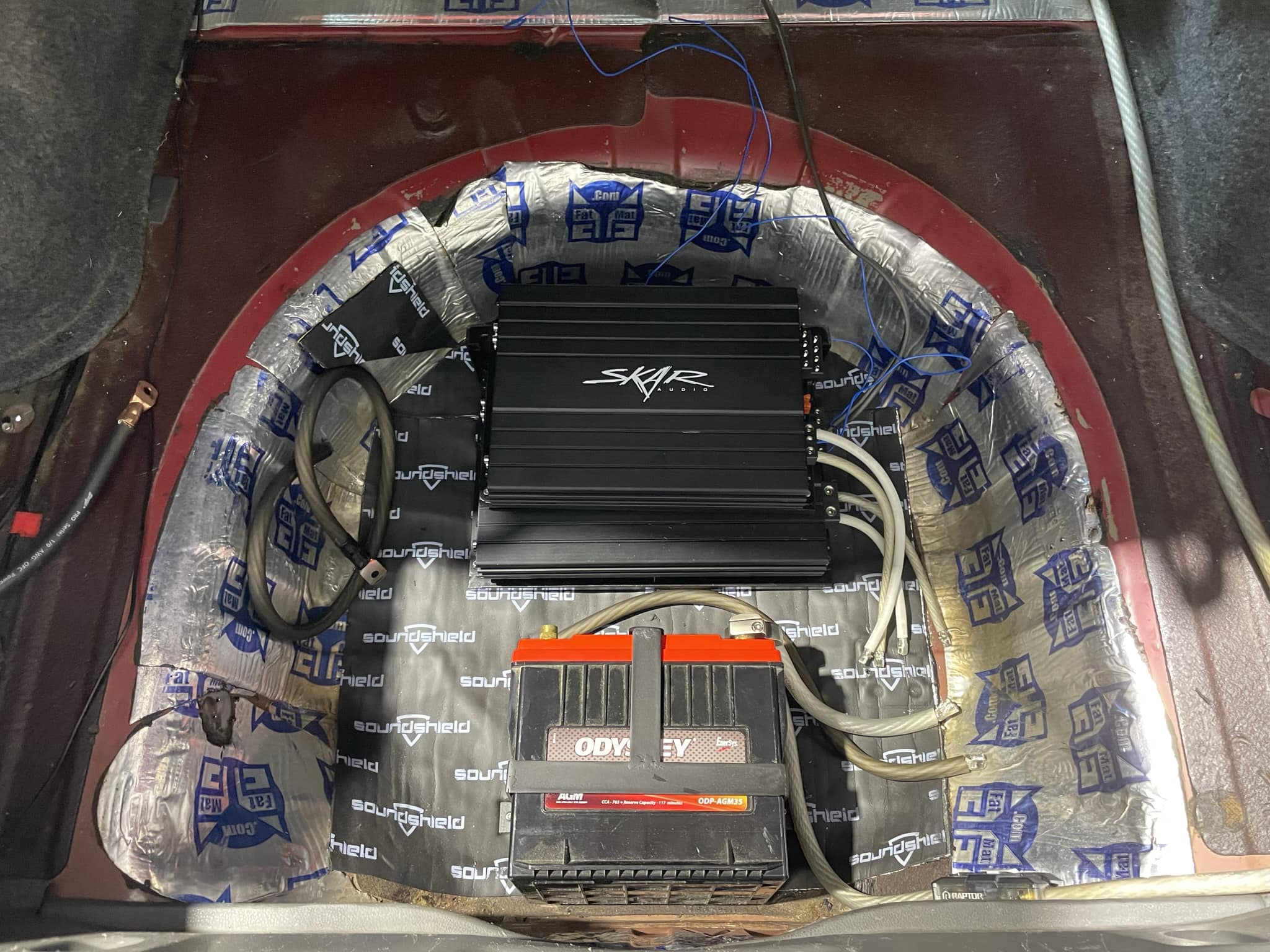
Credit: Voltaire D.
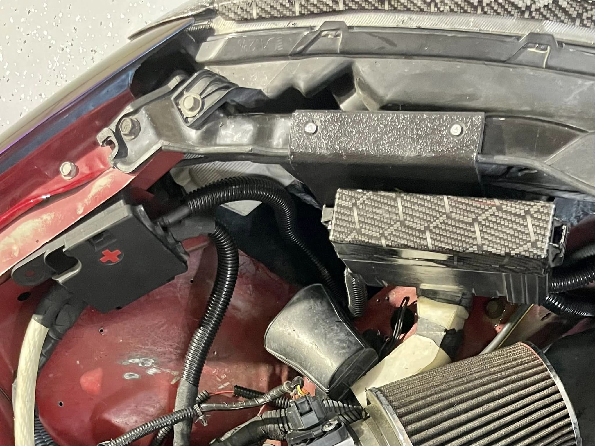
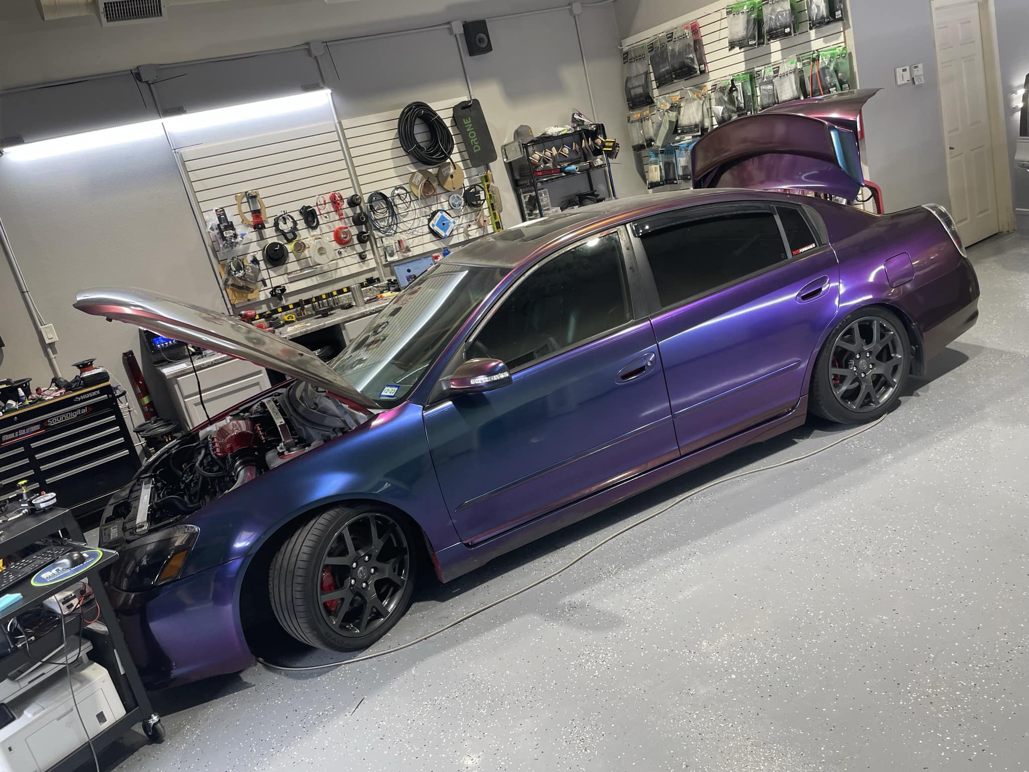
My daughter and I are getting started on the trunk again… as well as prepping the engine bay for things to come.
![]()

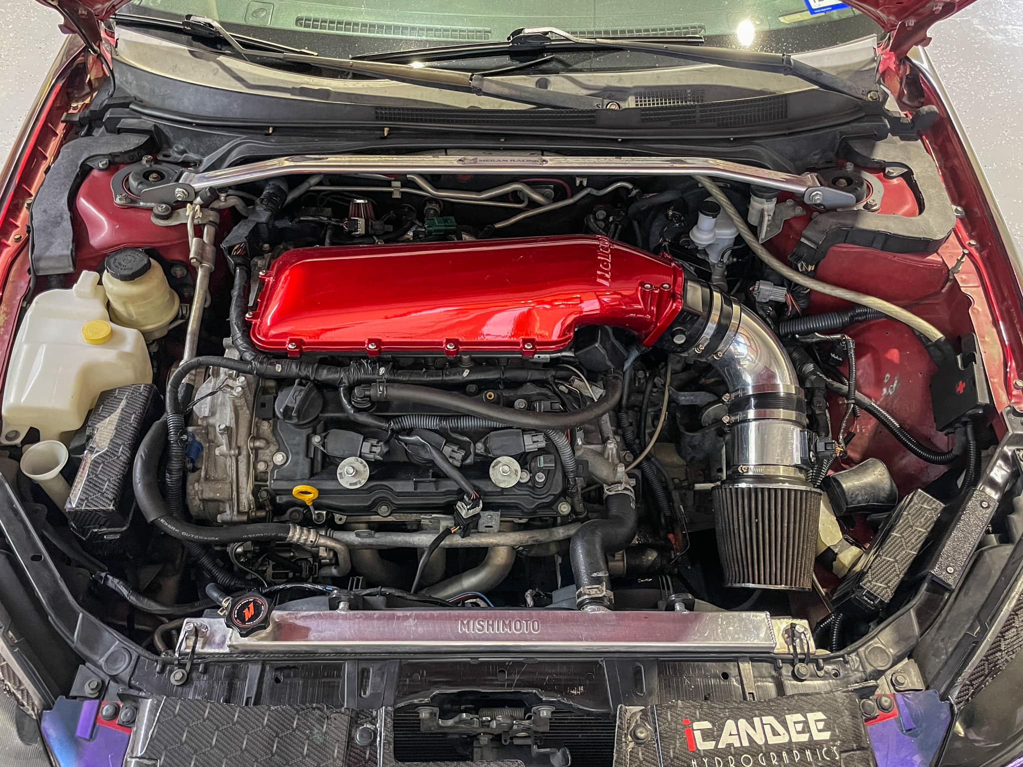
Credit: Wiley H.
Notes:
![]()
")
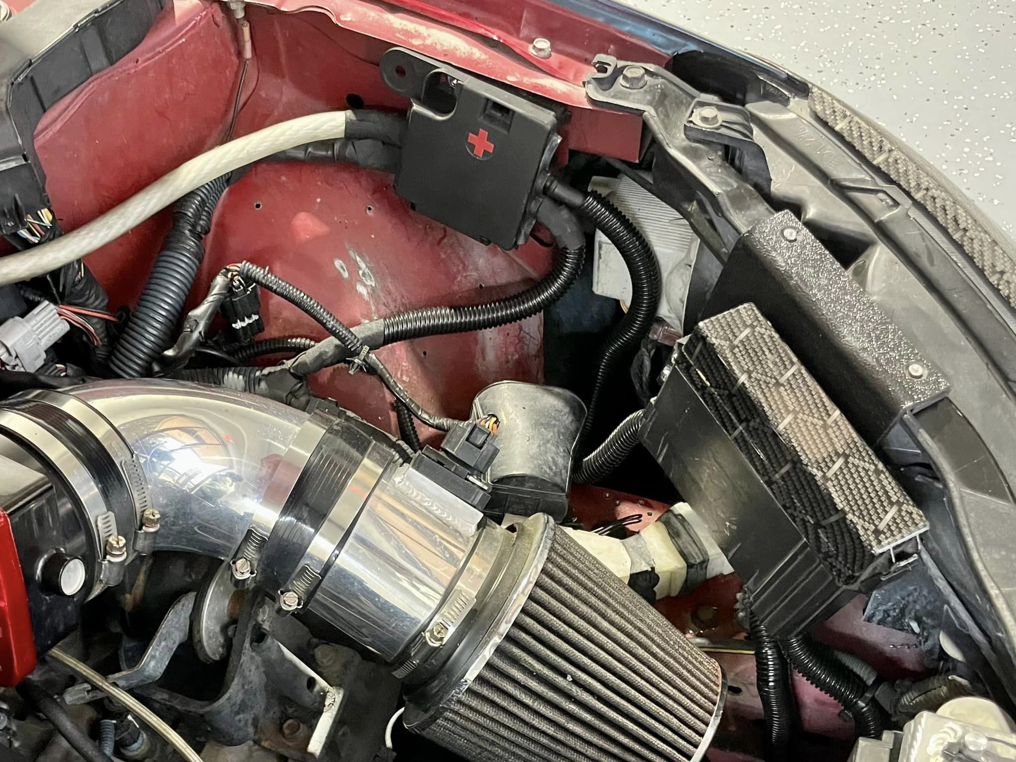
Credit: Kristan C.
I’m currently using a 100 shot wet kit that produces around 400 WHP. The nitrous is injected near the throttle body in the intake; in the first video, you can see the CEL light flashing. On that run, I melted a spark plug.


This video captures my final run of the day against a Scat Pack. By this time, the bottle pressure had dropped to 700, essentially reaching a cold state.
![]()
")
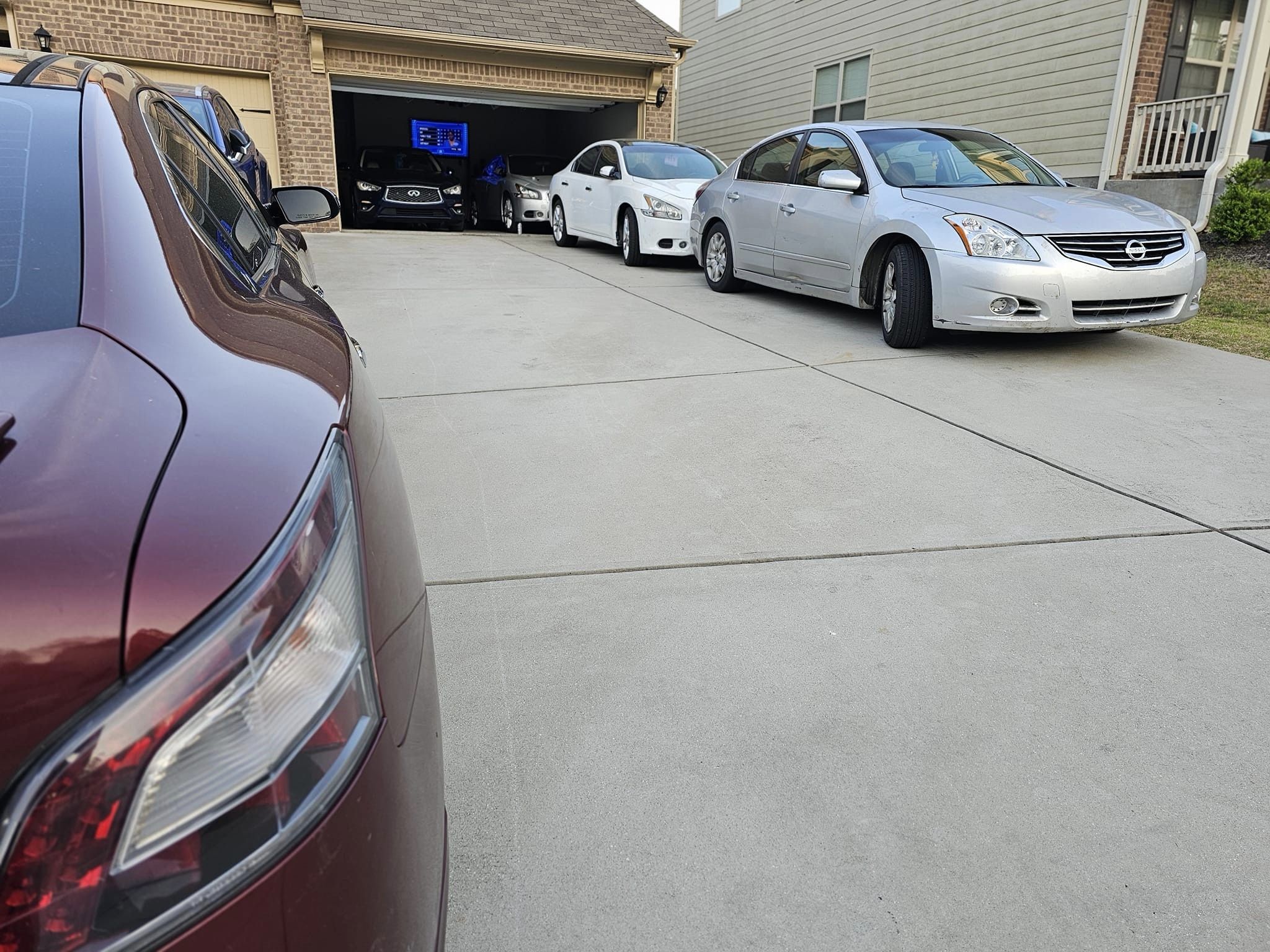
Community Member Credit: 95maxrider
I recently installed a 6 speed into my 4th gen using one of the how-tos, and while it was improved over the original guide, it left out a lot of details, so I wanted to make my own guide with new pictures and details to help people do this swap in the future. New parts are also available now that weren’t available when older guides were written which make the swap easier and reversible.
Various sized metric nuts and bolts
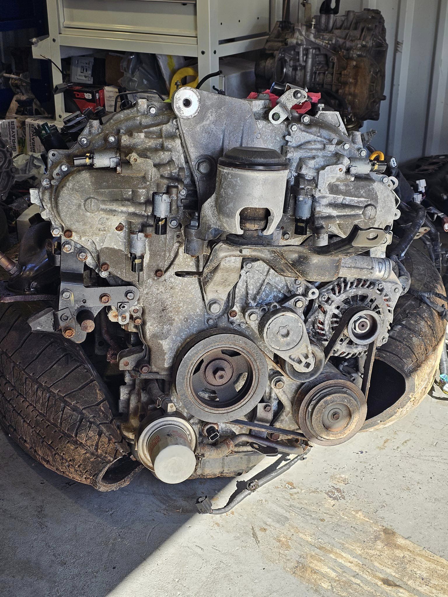
Identifying transmissions in junkyards:
You can also visually inspect the transmission and tell if it’s HLSD. If you look through the axle holes on either tranny you can see out the other side. On the HLSD you can see through with nothing in the way. You’ll see a perfect circle. On the open diff tranny there is a round bar in the way partially blocking the view through. You’ll see a half circle.
How to tell if HLSD?
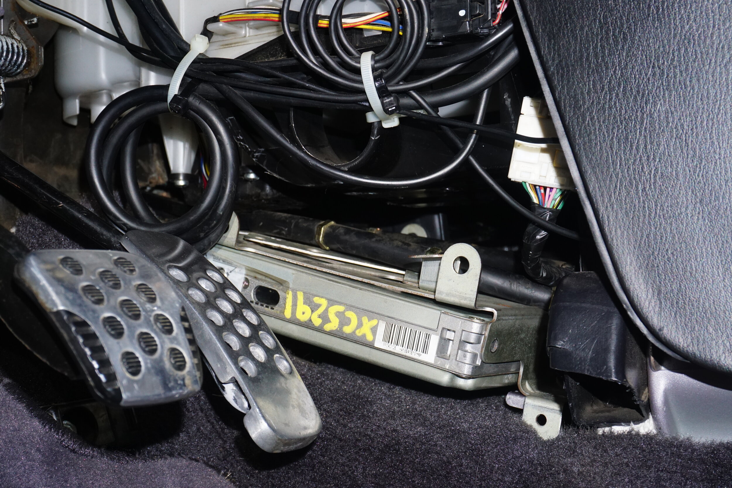
-Metal pedals with rubber grips
-Plate on firewall by driver, RS6F51H, H as last digit means HLSD, A is open diff
6th gen axle info:
6th gen passenger side axles are slightly longer than 5.5th gen axles, and 5.5th gen axles are quite a bit longer than 4th gen axles. When installed, 5.5th gen axles are already compressed and close to binding, so 6th gen axles are not recommended for 4th gens. Also, the carrier bracket for 6th gens is very different from 4th/5.5th gens, and can only be used with 6th gen axles.
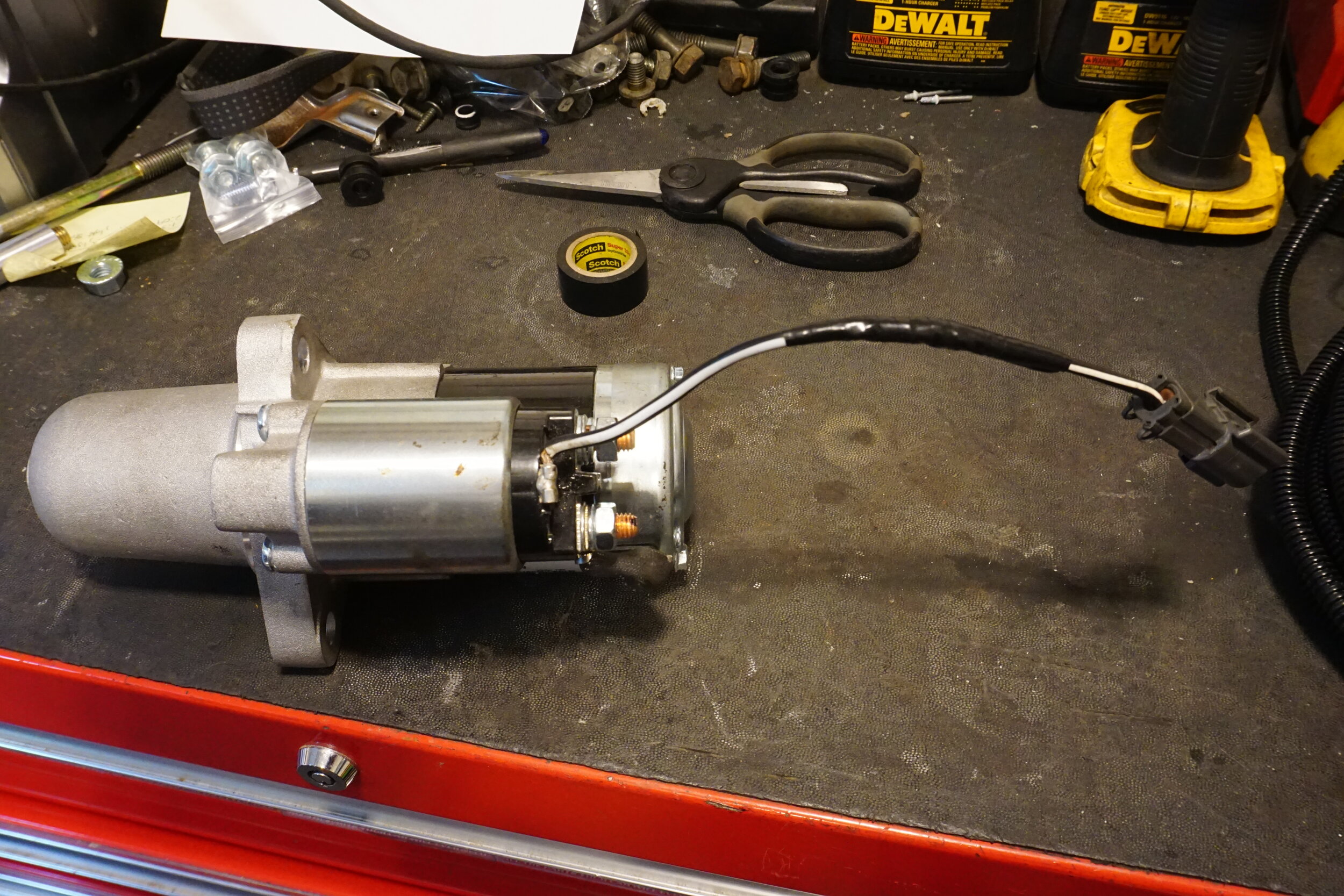
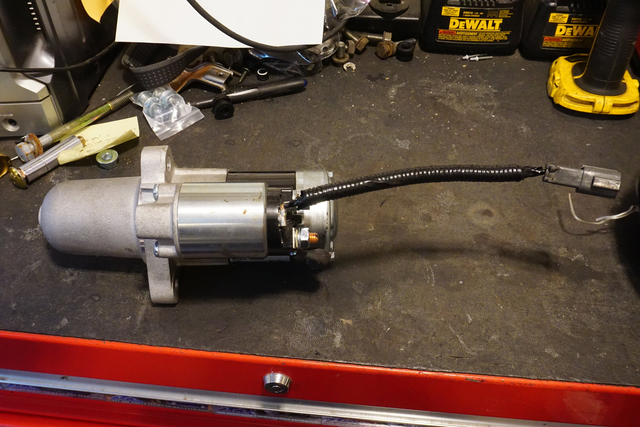
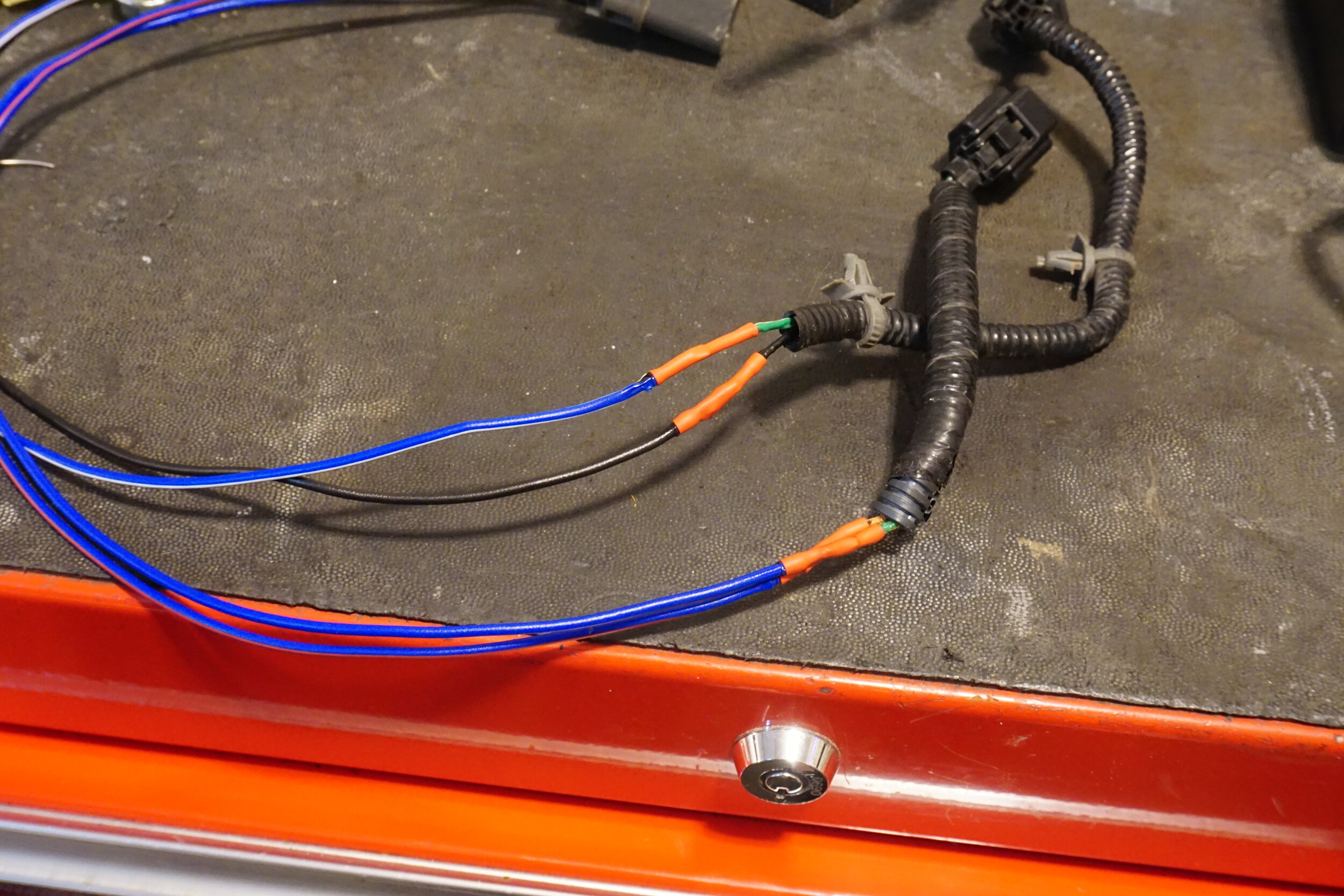
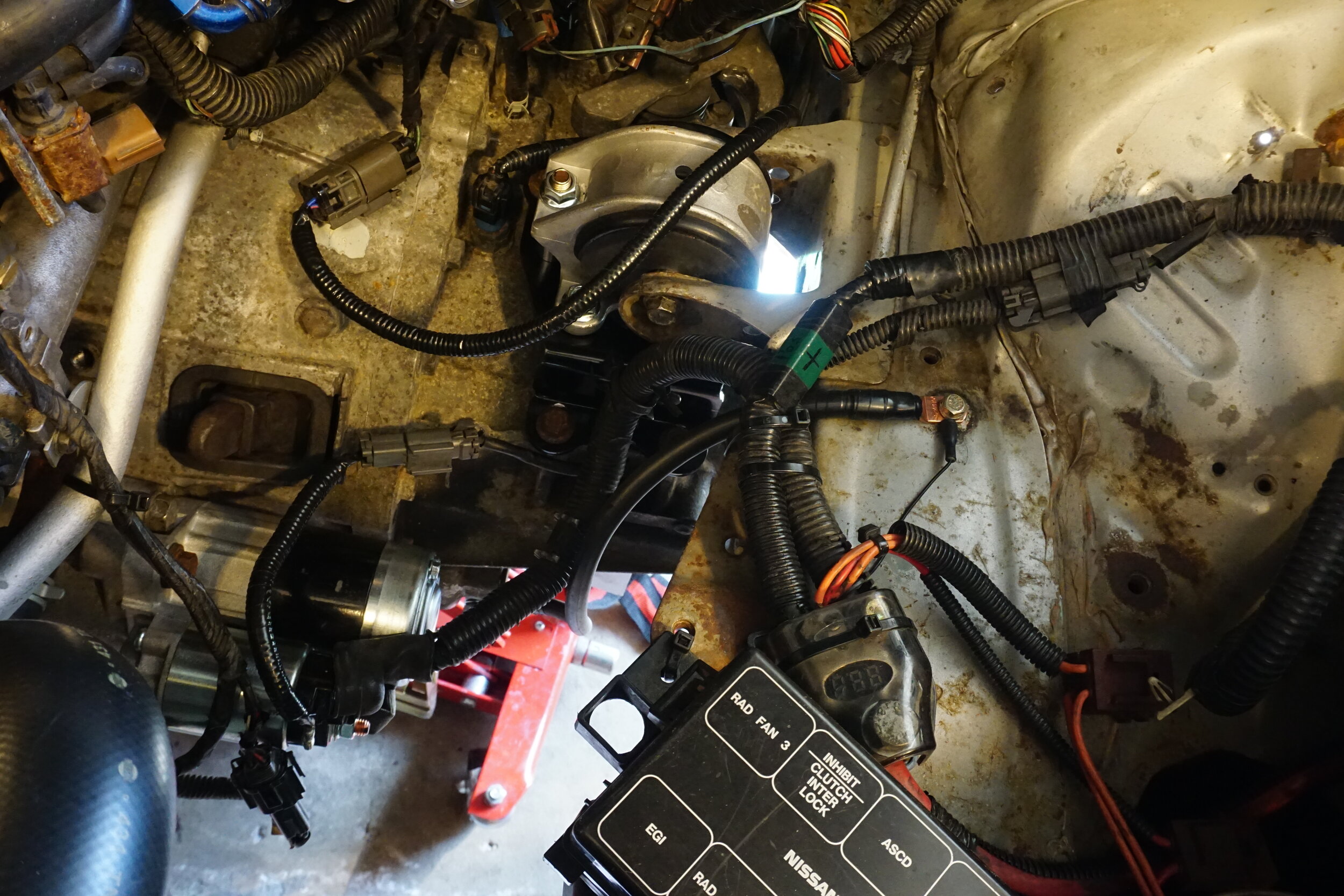
Wiring up the 6 speed starter:
The 6 speed starter ground cable is a female connector, and so is the connector on the engine harness. I cut the male connector off of a 5 speed starter and soldered it onto the 6spd starter. Don’t forget to slide some heat shrink tubing on the wire before soldering together. I forgot to do this! For extra protection you can wrap the area with electrical tape. And for an OEM look, protect all the wires with split wire loom tubing.
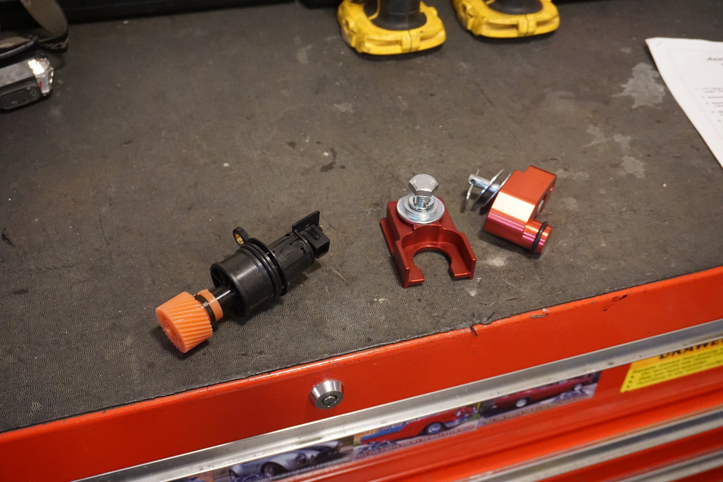
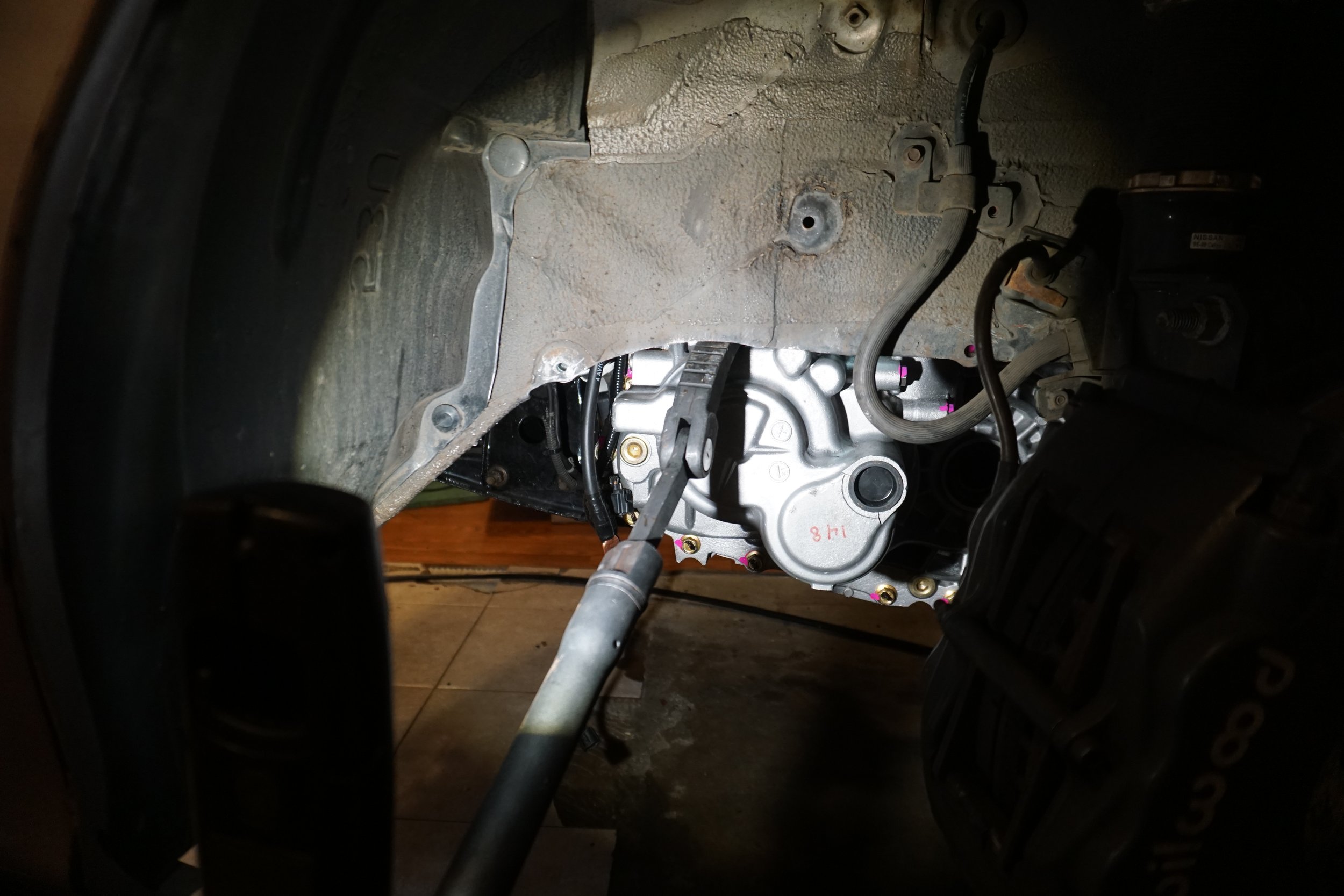
Wiring up the park/neutral position sensors for the 6 speed:
On 5 speeds the PNP switch/sensor is a single piece on the bottom of the trans. On 6 speeds, it was switched to being two switches/sensors, so you will need to need to splice wires together so your car gets the right signals and doesn’t throw a CEL. You want your reverse lights to work, don’t you? On the 6 speed, the blue sensor on top is for reverse lights, and the black one on side back is for neutral. Cut off the wires from the PNP switch on your 5 speed so you’re left with about 12″ of wires and the connector that plugs into your body harness. Leave the switch in the 5 speed. Here’s how you’re going to wire that up to the connectors for the 6 speed.
Reverse (blue connector on top of the trans)
Connect the orange (12V+) wire on the 6 speed harness to the blue/red wire on the 5 speed PNP harness.
Connect the green/white (to backup lamps) wire on the 6 speed harness to the solid blue wire on the 5 speed PNP harness.
Neutral (black connector on the back of the trans)
Connect the green/white (to ECM) wire on the 6 speed harness to the blue/white wire on the 5 speed PNP harness.
Connect the black (to ground) wire on the 6 speed harness to the black wire on the 5 speed PNP harness.
Make sure you slide some heat shrink onto the wires before you crimp or solder them together to protect the connection from moisture. For extra protection you can wrap the area with electrical tape. And for an OEM look, protect all the wires with split wire loom tubing.
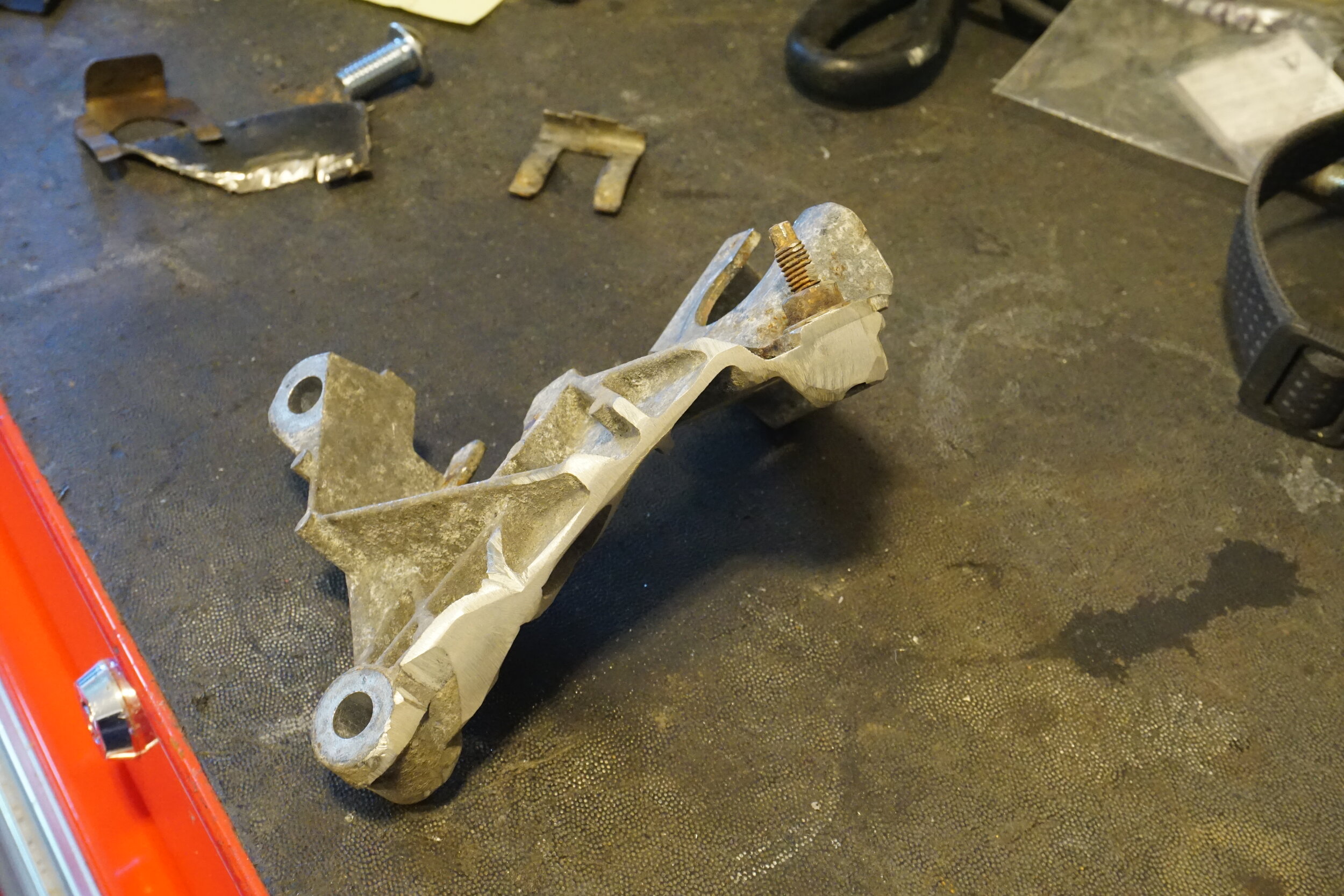
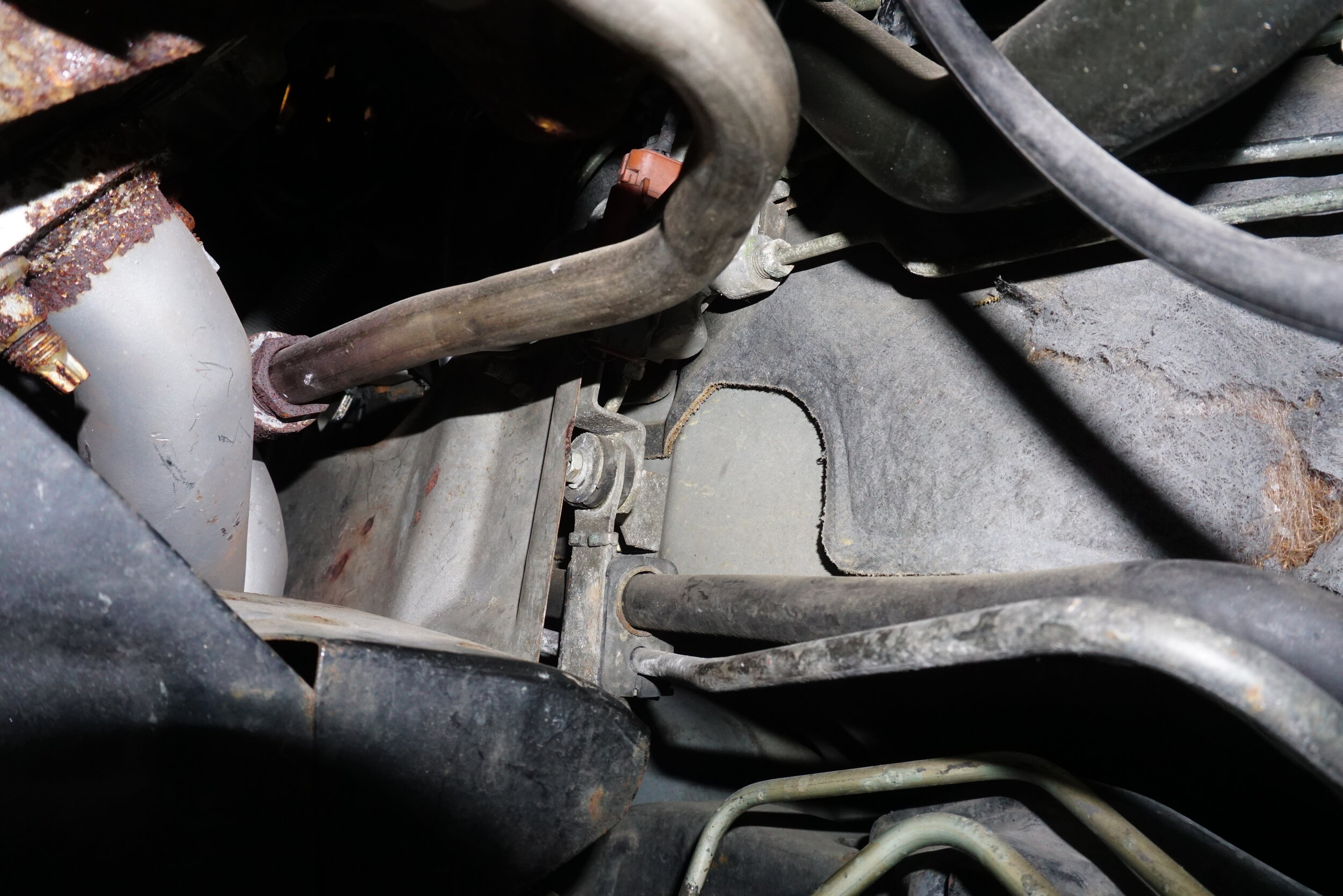
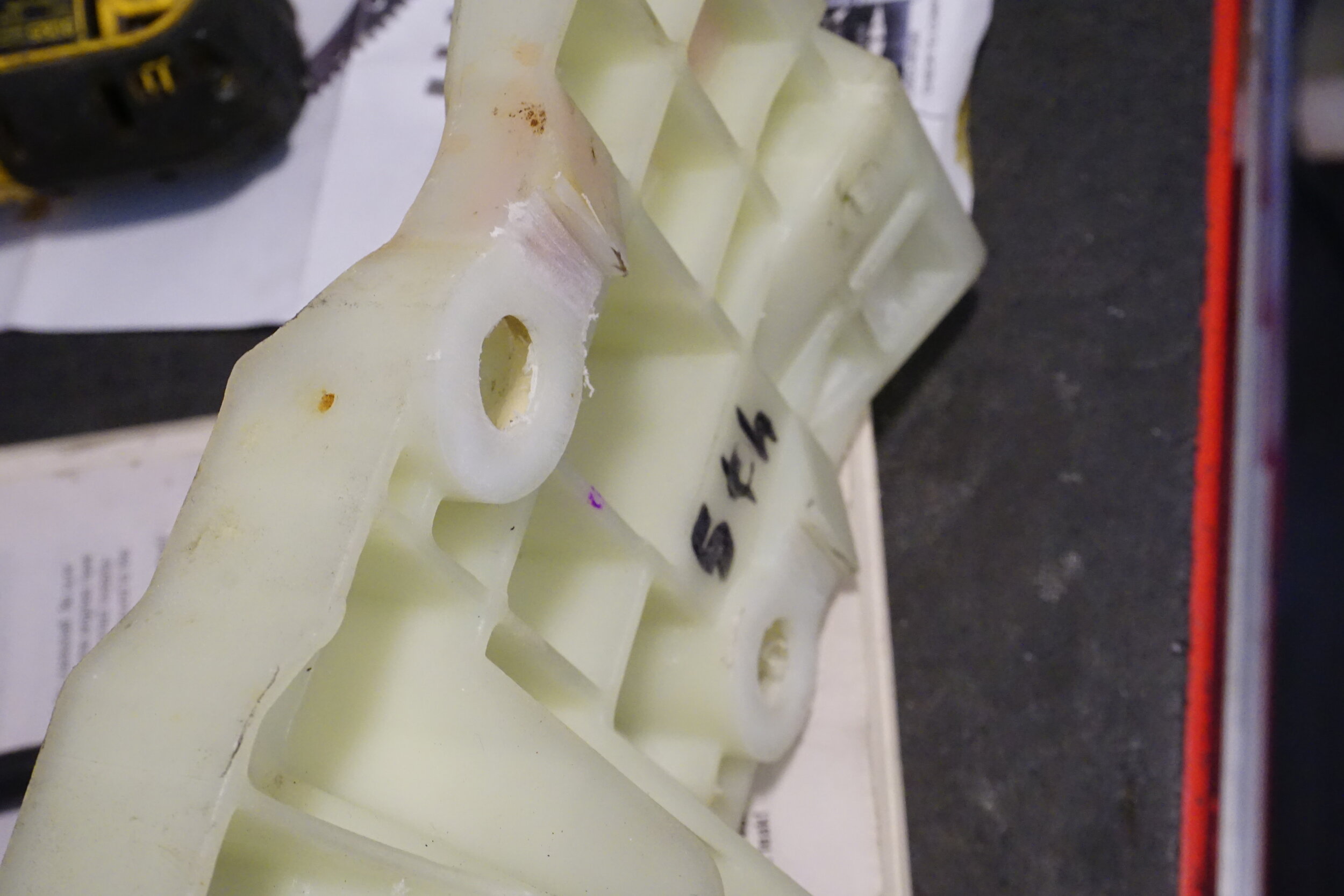
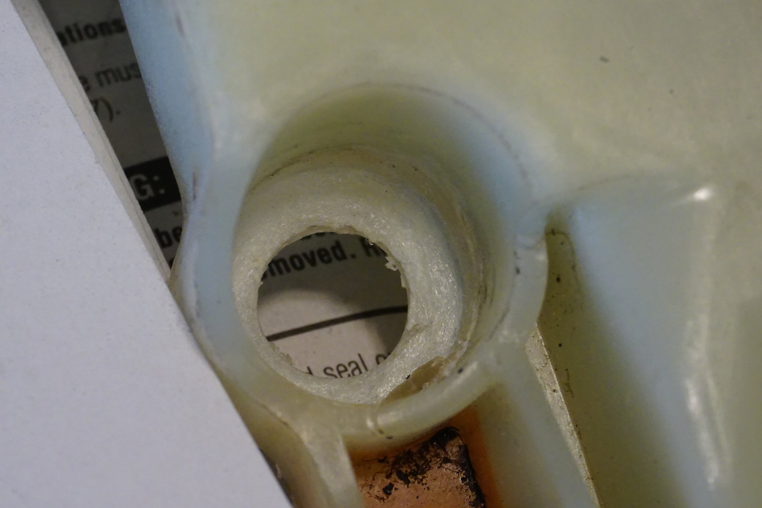
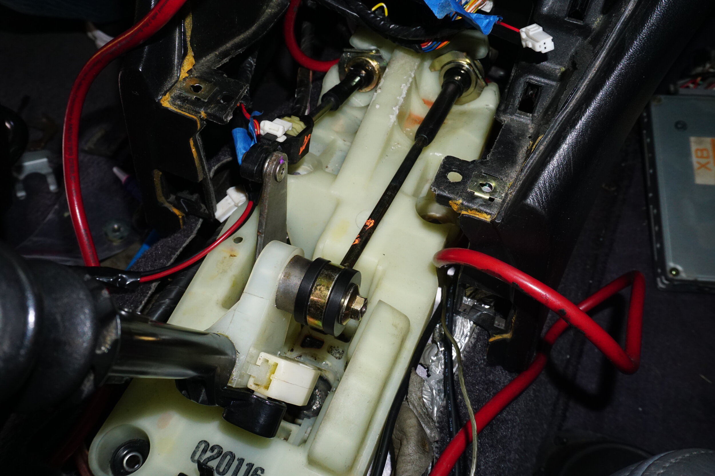
1995/96 cars with giant EVAP canister on firewall under master cylinder:
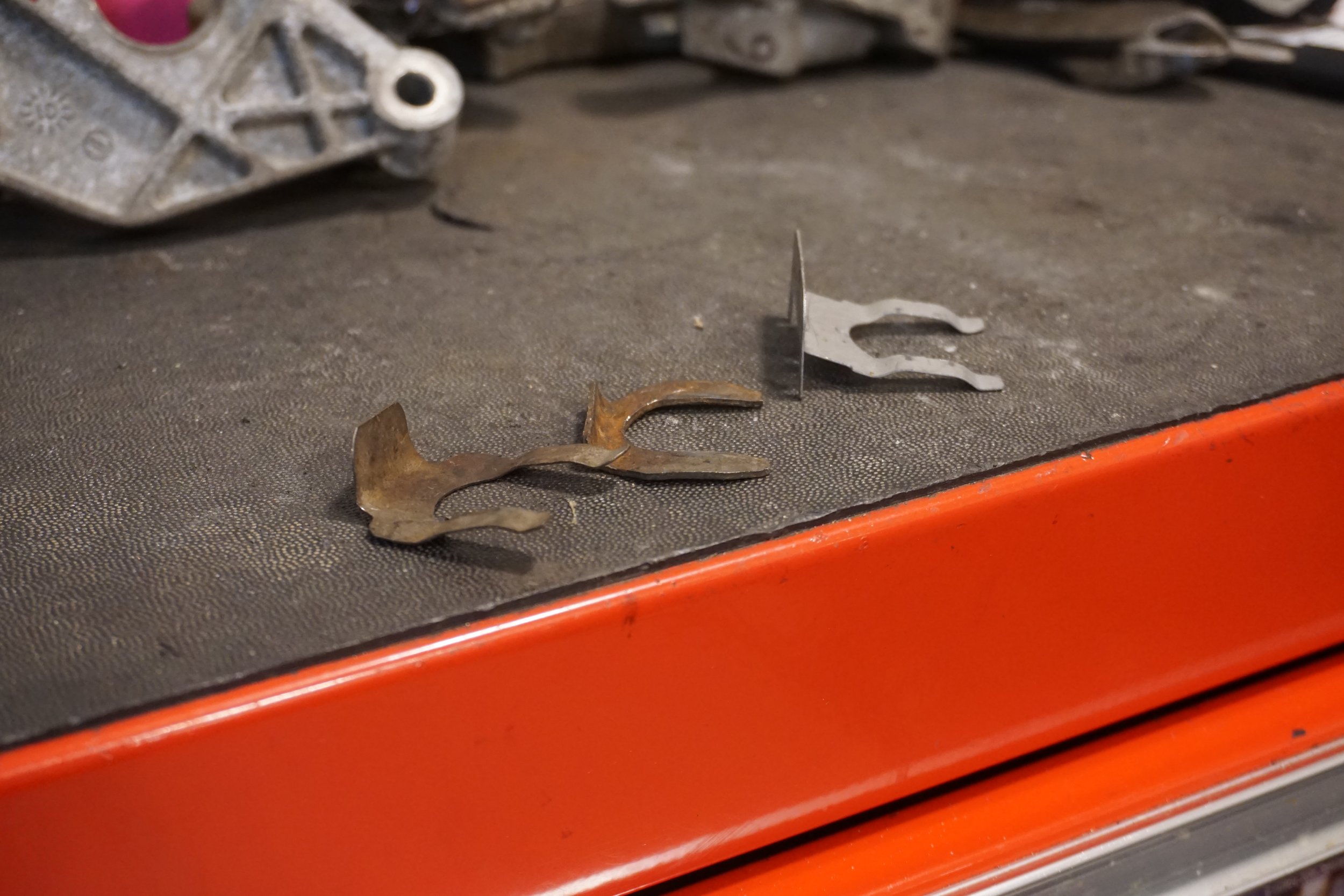
You will need to cut/grind the shifter cable bracket so it doesn’t break your EVAP canister when you try to get the trans mounted in place.
Interference:
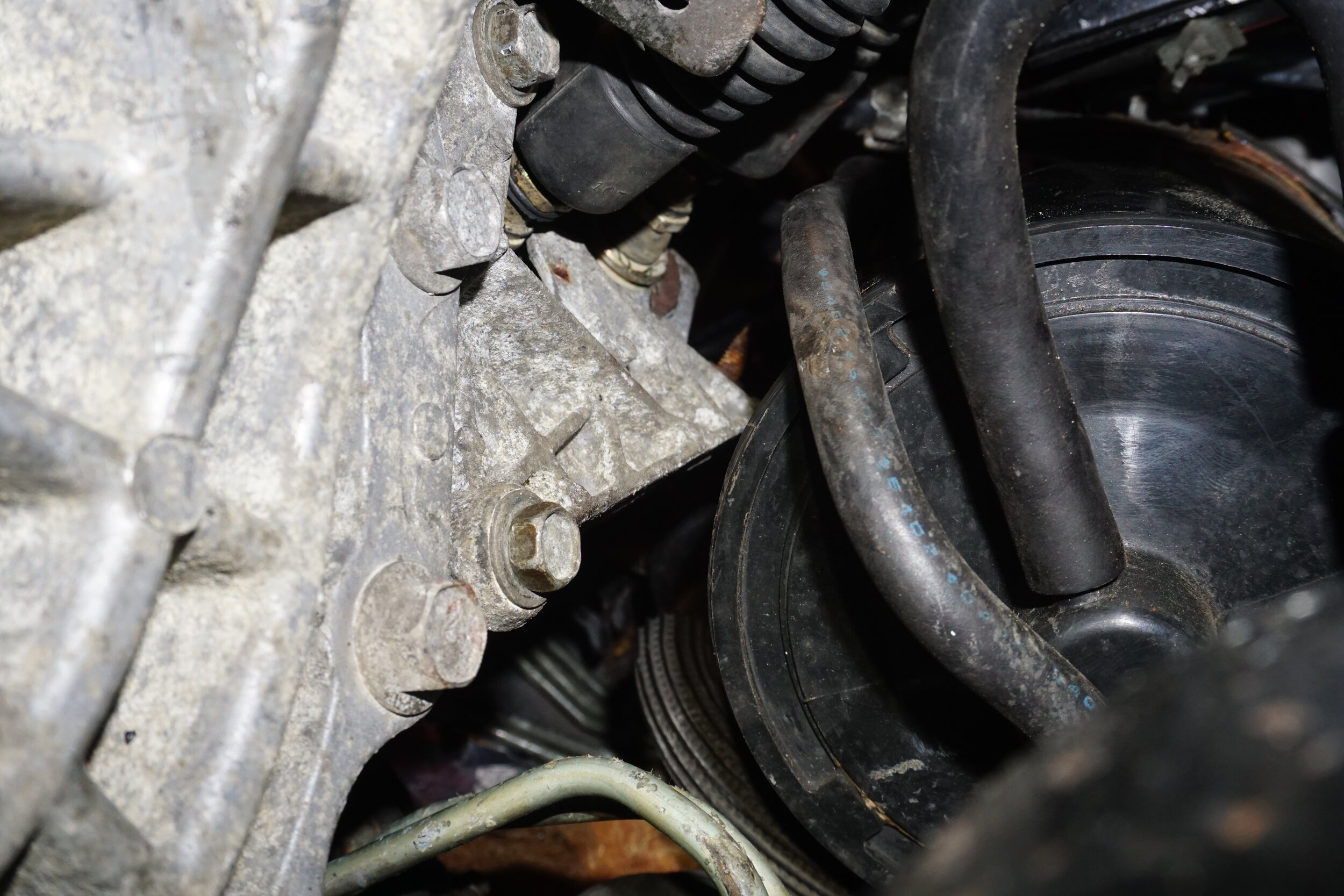
Original:
After cutting and grinding:
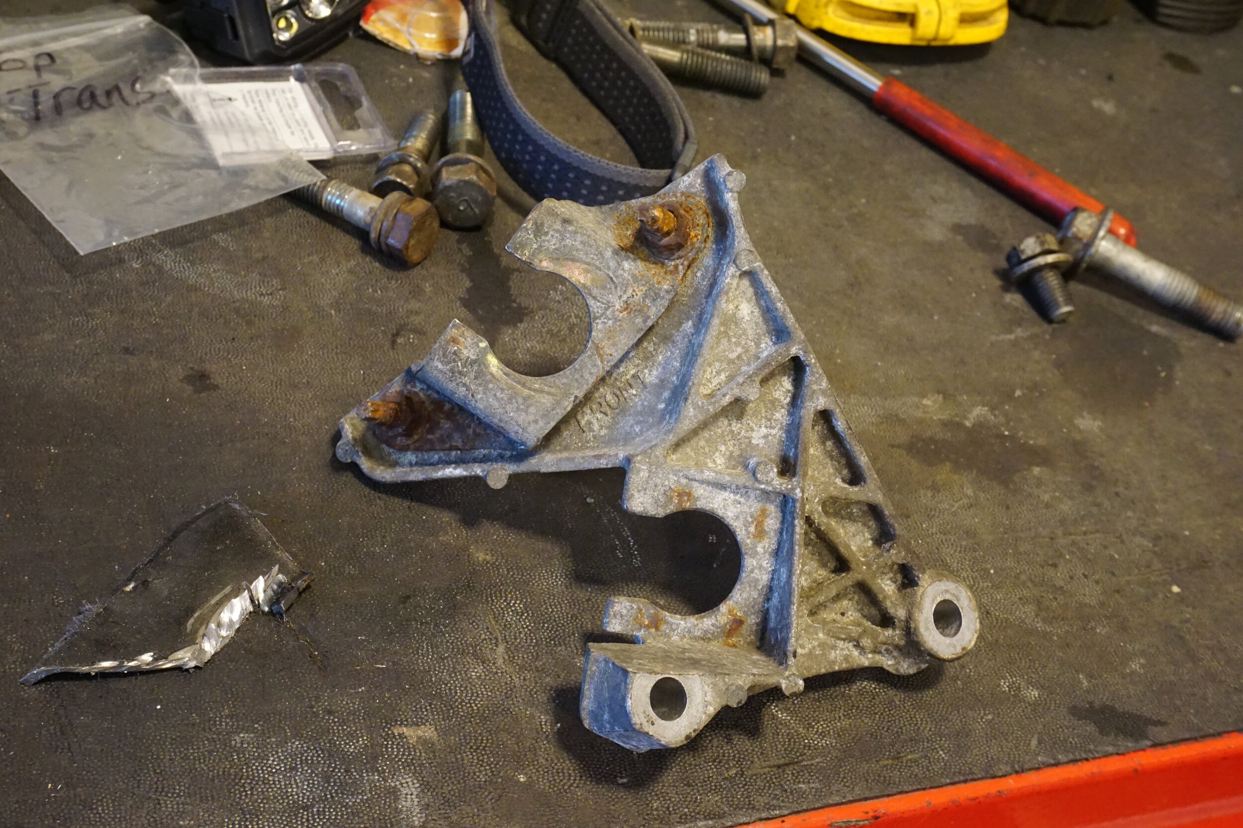
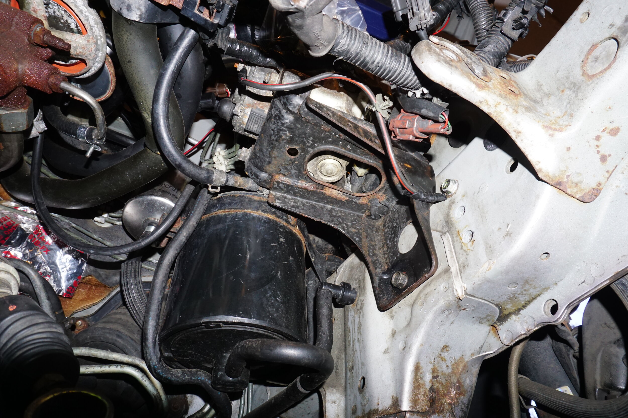
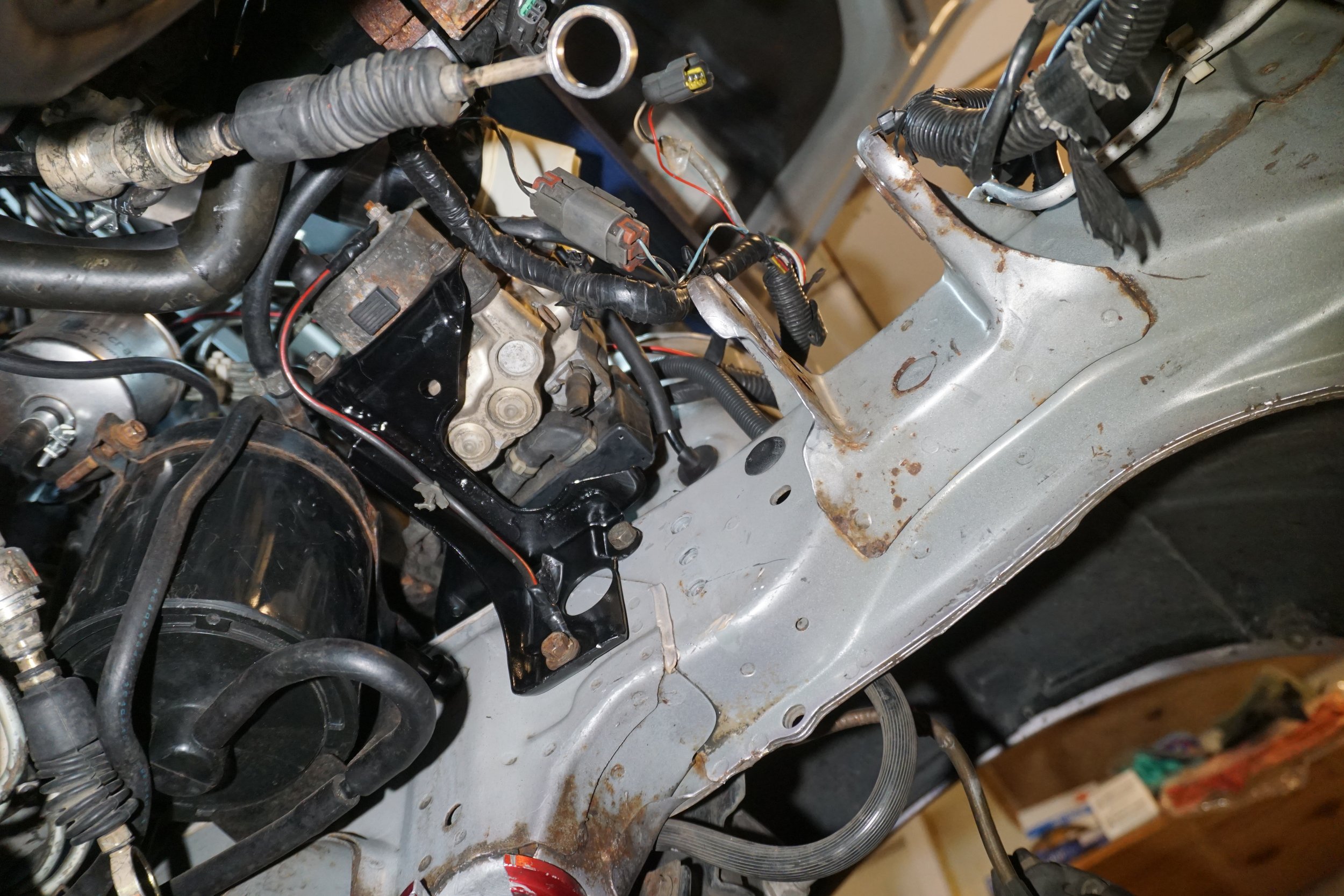
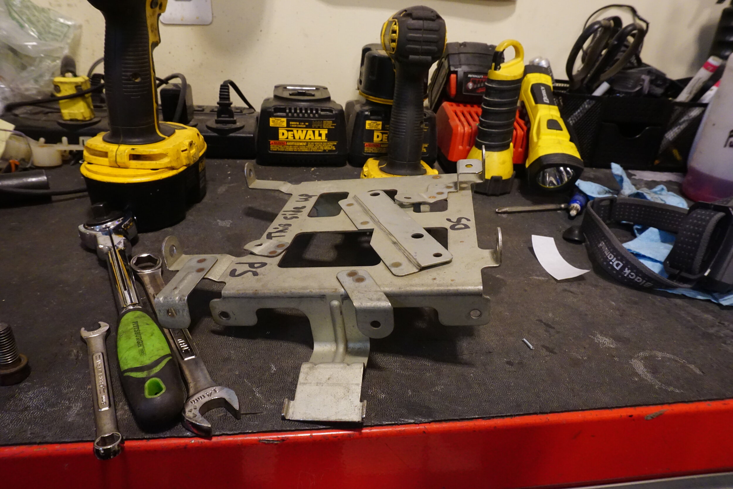
If your car has ABS:
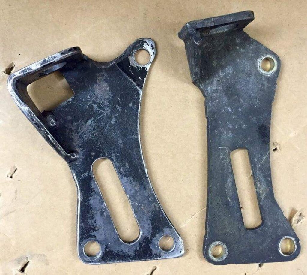
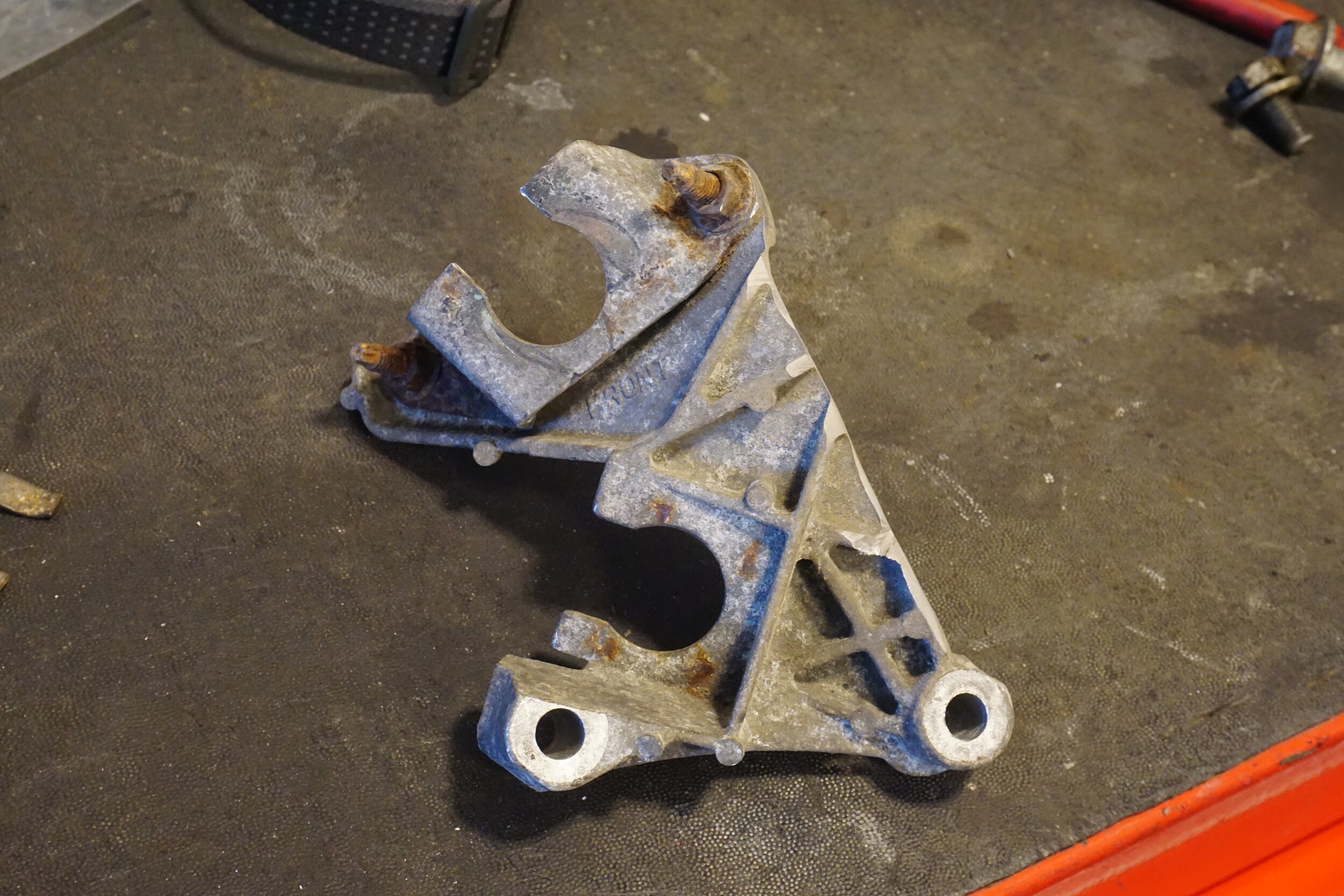
Previous guides correctly noted that the bracket for the ABS pump (under and in front of master cylinder) gets in the way of the shifter cables/levers and said to remove the bracket for the ABS pump. I believe this is unsafe and strongly recommend you do not do this. Their solution was to hang the heavy ABS pump with a zip tie from the master cylinder. This is a bad idea and would not pass tech inspection at any sort of racing organization. The proper solution to this problem is to use either an angle grinder with a cutoff wheel or a Dremel with reinforced cutoff wheels to remove portions of the bracket that interfere with the shifter parts, and leave the rest of the bracket to support the pump. This is much easier with the bracket removed from the vehicle, so remove and cut yours while you don’t have a transmission in the car. I recommend painting the bracket when you’re done cutting to prevent the bare metal from rusting.
Original bracket:
Cut and painted:
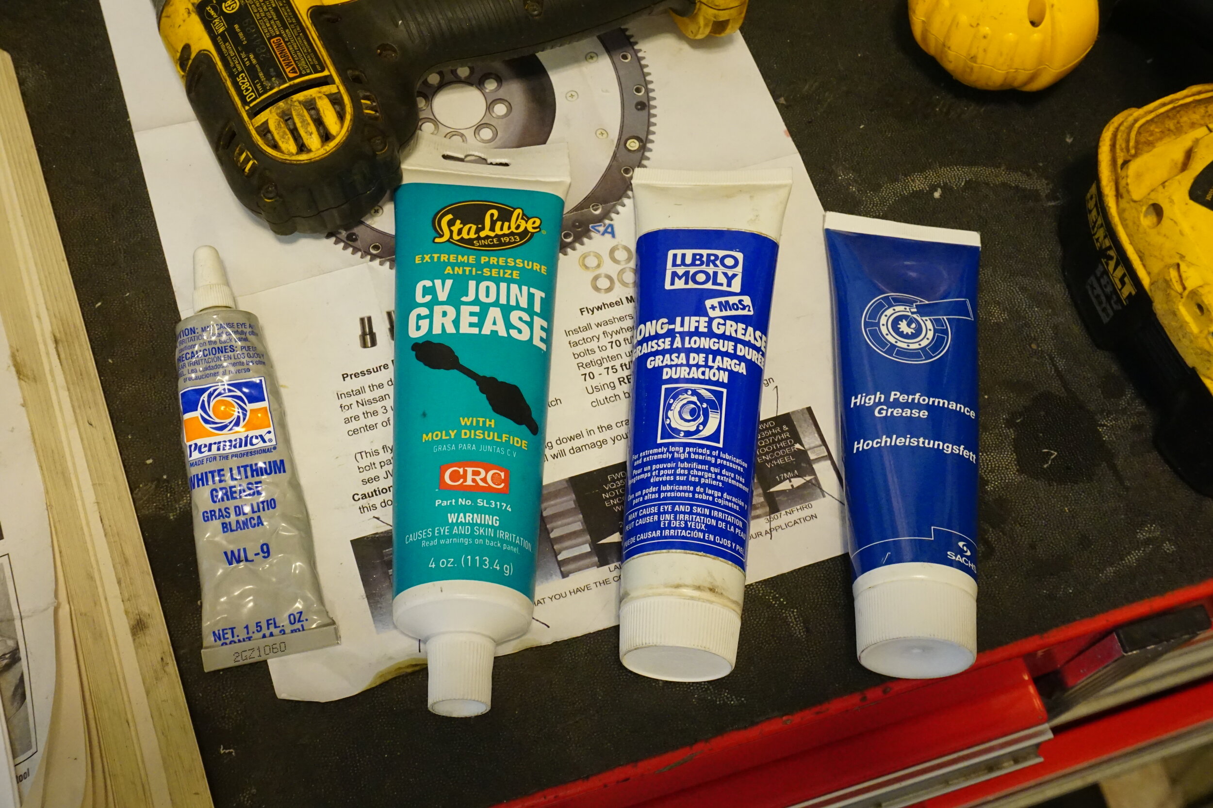
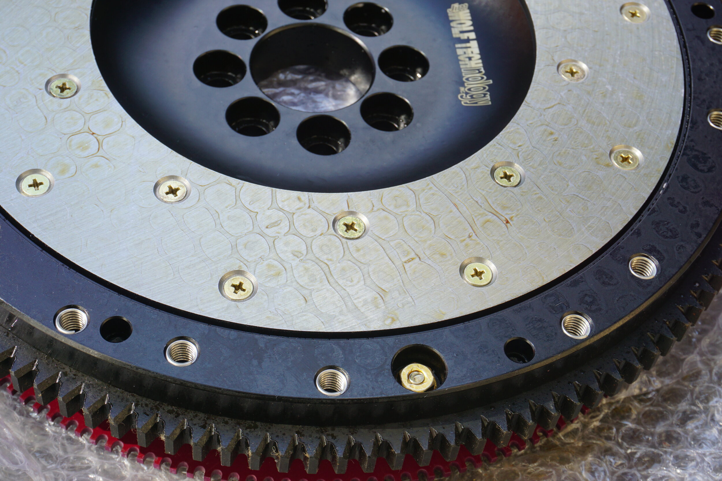
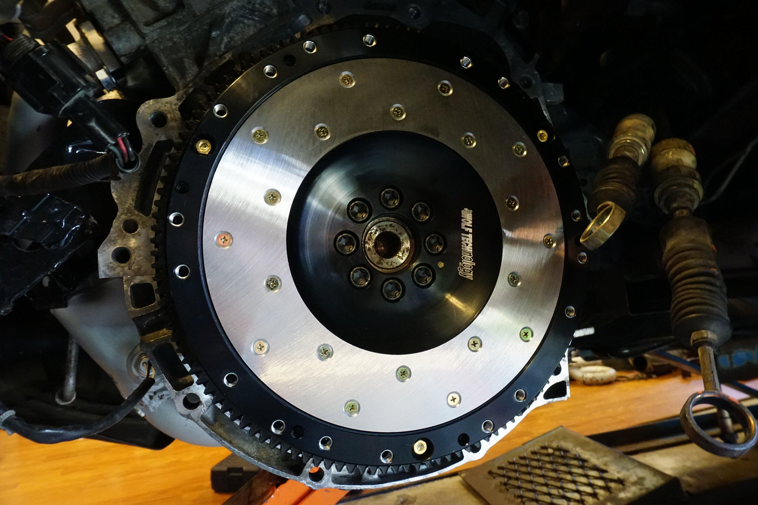
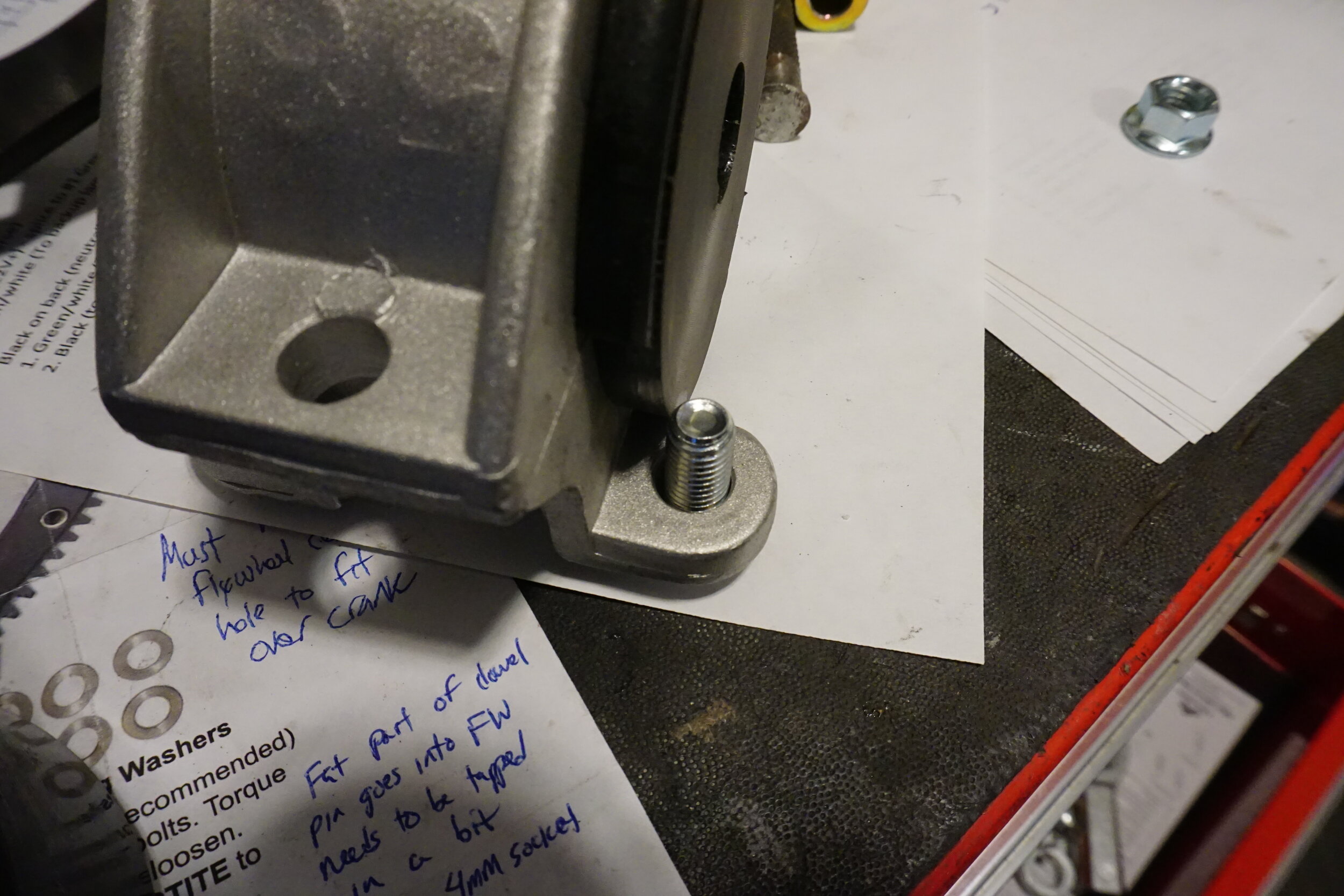
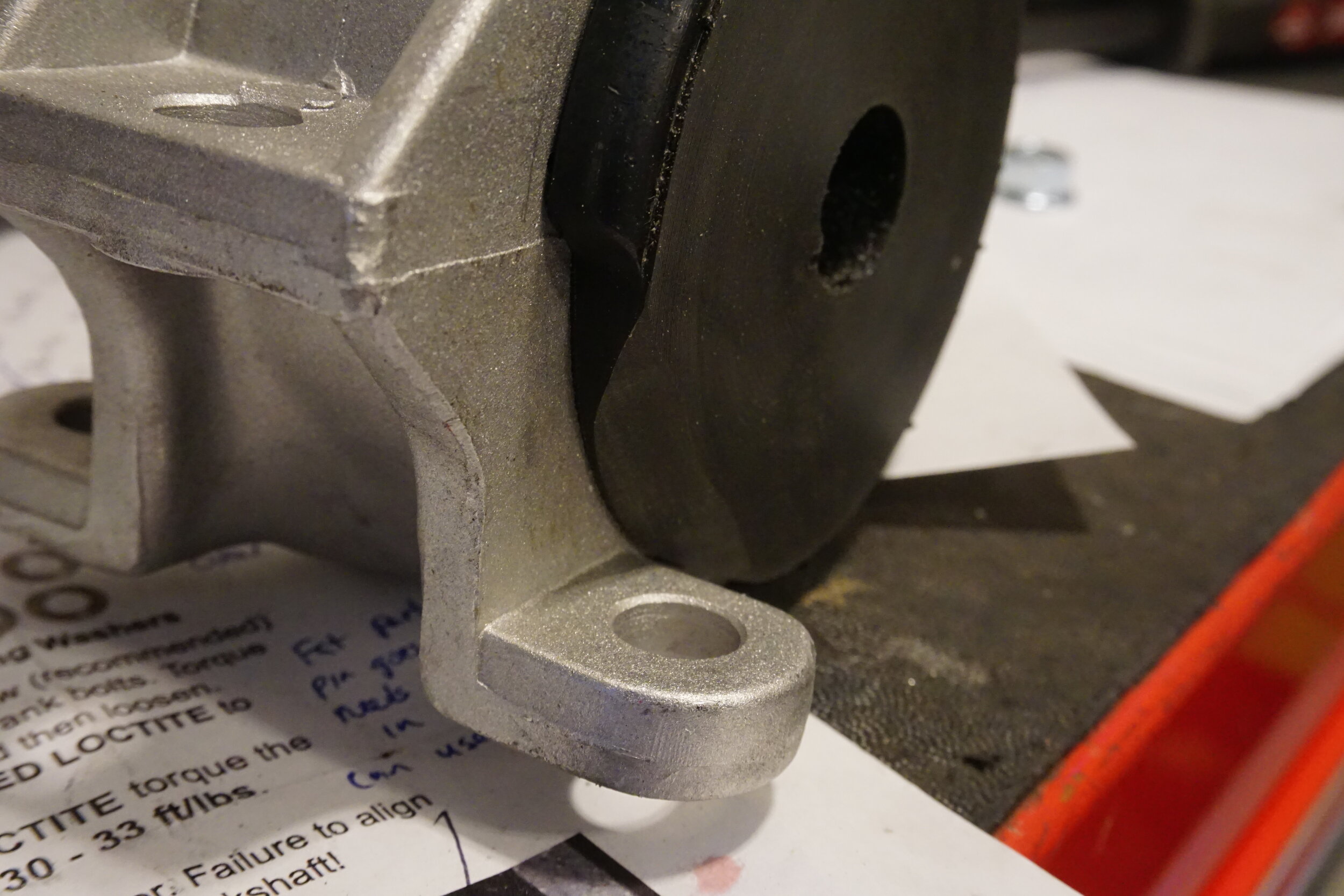
JWT Flywheel: To install the custom timing ring from Schmellyfart onto your JWT or Fidanza flywheel, you will need some sort of torch to apply heat to the screws that hold on the ring that JWT supplies. JWT uses Red Loctite to the small screws, so if they are not heated up you run a very good chance of stripping them, which is really going to suck. Heat them up one at a time, then loosen by hand, do not use an impact. One they are all removed, remove the JWT timing ring and install the one from Schmellyfart. Apply Red Loctite to all the little screws and reinstall them. Since they are so small there is no torque spec, just make them hand tight and do not tighten with an impact.
The JWT flywheel arrived with a thick waxy/oily coating to prevent the surface from rusting. This will need to be fully removed before installing so you don’t contaminate your clutch disc material. I first used some 3M Adhesive Remover on rags, making sure to also remove the wax from the top of the screw heads. Once it looked clean, I blasted the whole thing with brake cleaner to remove any residue. Make sure you also spray your new pressure place with brake cleaner for the same reason.
To install the JWT flywheel follow the included directions. Mine barely fit over the crankshaft and had to be hammered on with a rubber mallet. I recommend leaving the flywheel in the sun for a few hours before installing so the metal heats up and expands. You will need something to keep the crankshaft from rotating while you torque the bolts that attach the flywheel to the crank. I used the OTC Pulley Holder tool mentioned above, although some people will just put a socket over the crank bolt and hold it with a breaker bar. I chose to have a helper hold the pulley holder tool for me while I worked the flywheel bolts. It’s very important that you torque the flywheel bolts to the proper spec and that the flywheel is perfectly flush with the crank. JWT also recommends using Red Loctite on the flywheel bolts, and while that may make them damn near impossible to remove in the future, I chose to follow their instructions. I just didn’t apply very much. If you need to remove them later, be sure to use plenty of heat.
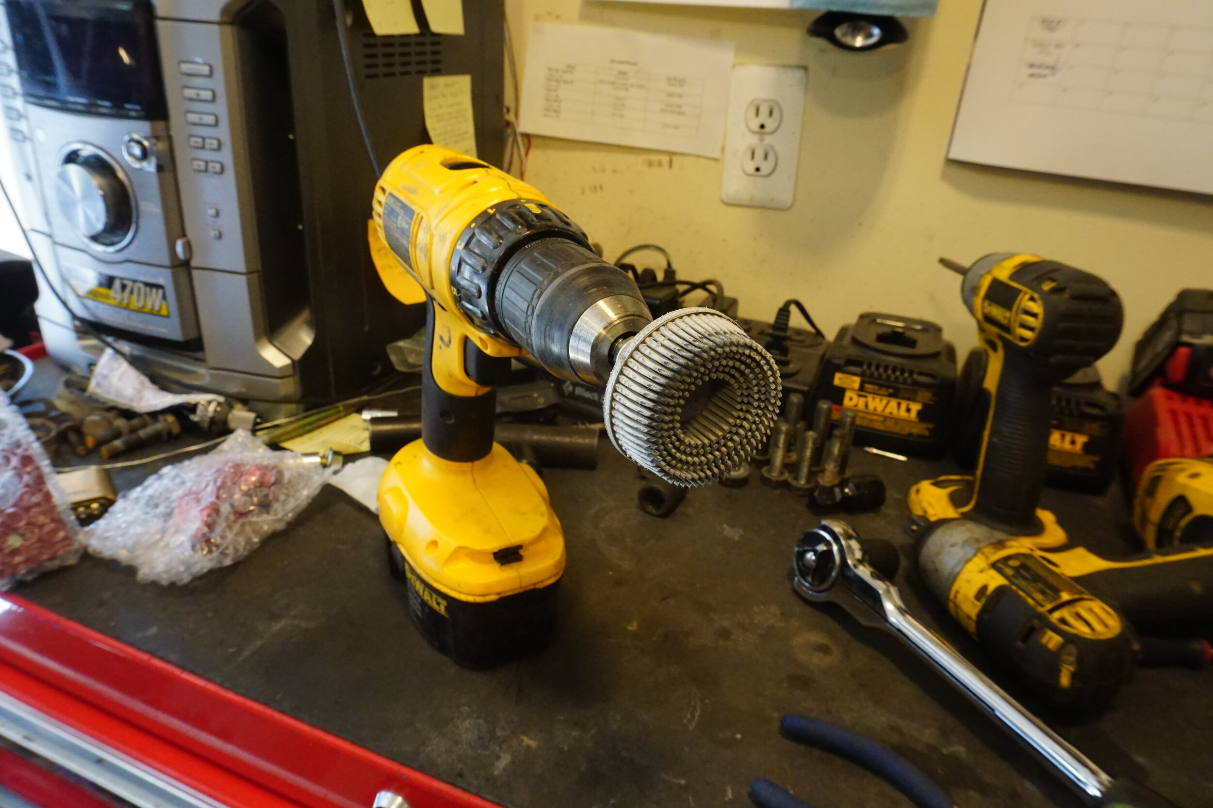
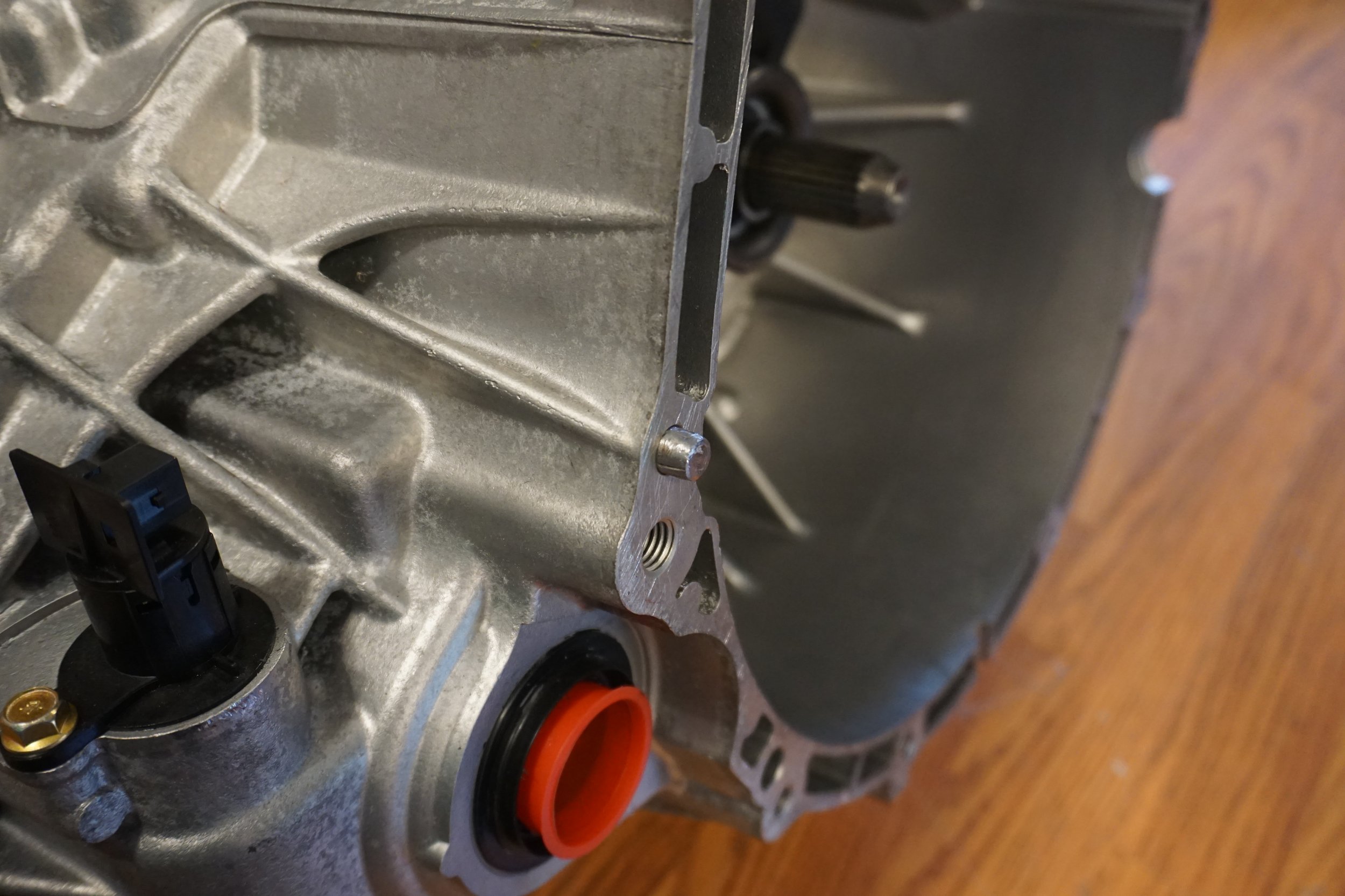
Don’t forget to very thoroughly clean up the mating surface between the engine and transmission, otherwise your starter might not have a good ground path and the car won’t start. Clean both the engine and the transmission! I used one of these plastic bristle things so I wouldn’t damage the aluminum.
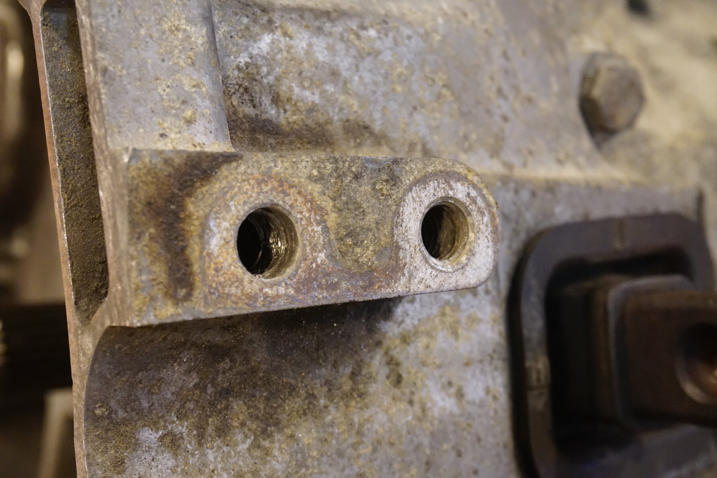
Now is a good time to chase the threads for the two bolts that hold the slave cylinder in place, mine were pretty grungy.
I recommend also cleaning up the area around the ground cable on the transmission so it can make a good connection.
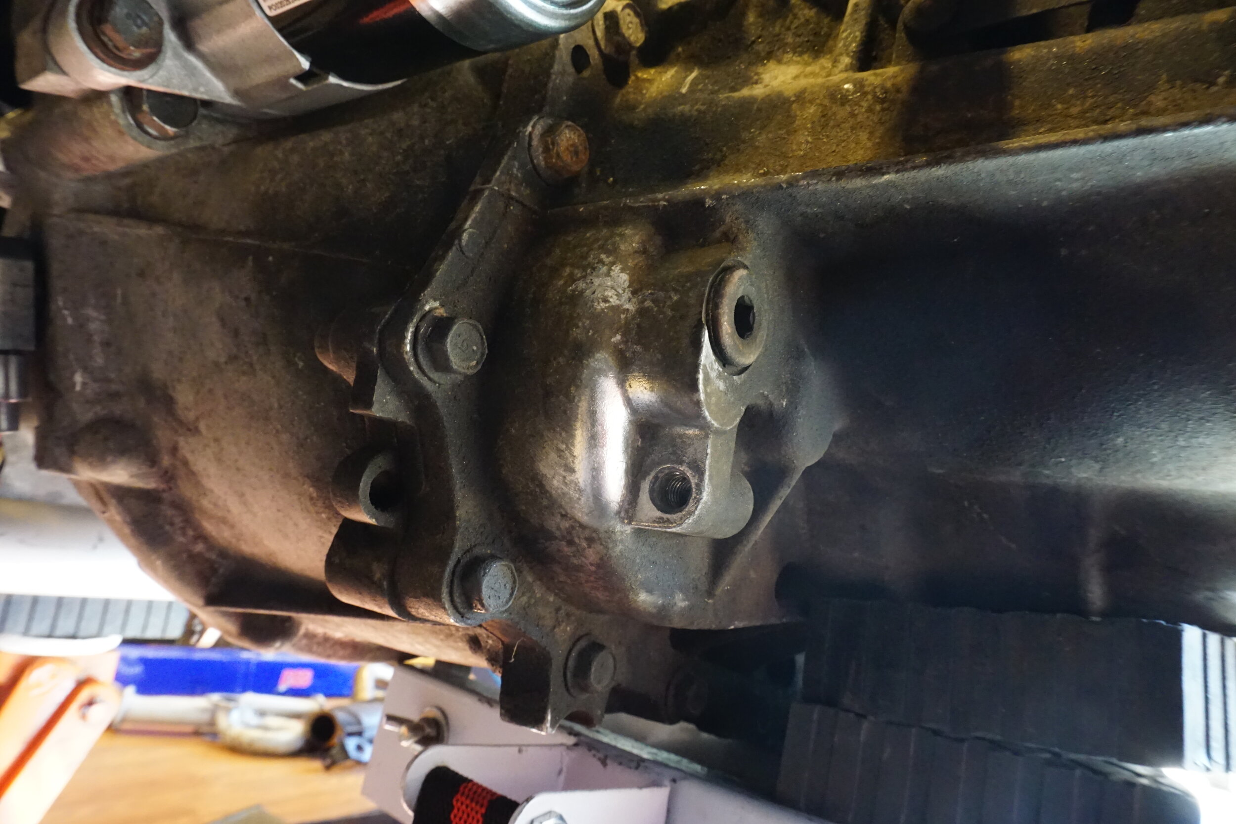
Make a new ground cable using the appropriate glue-lined heat shrink.
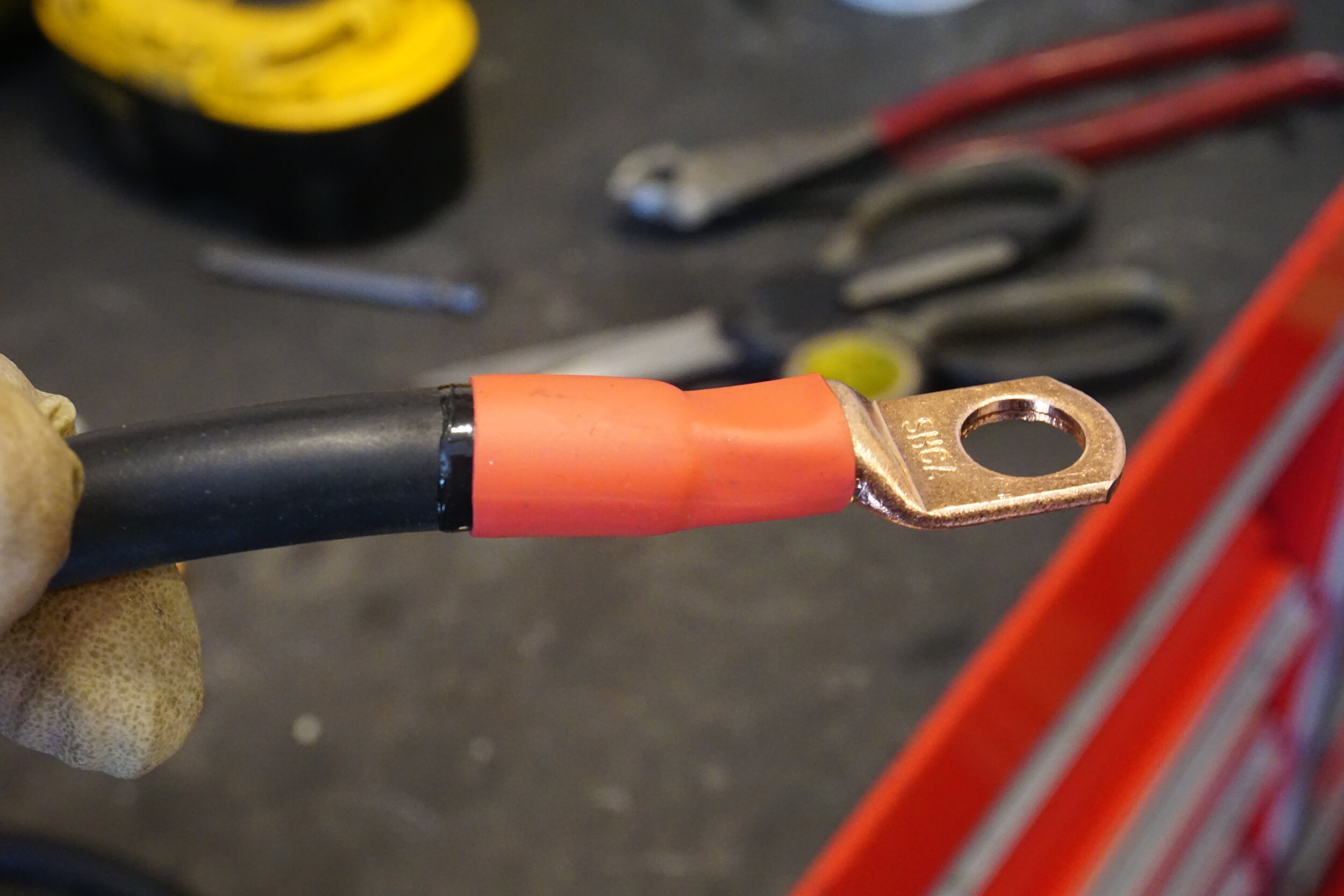
Here’s how mine looked when I was done:
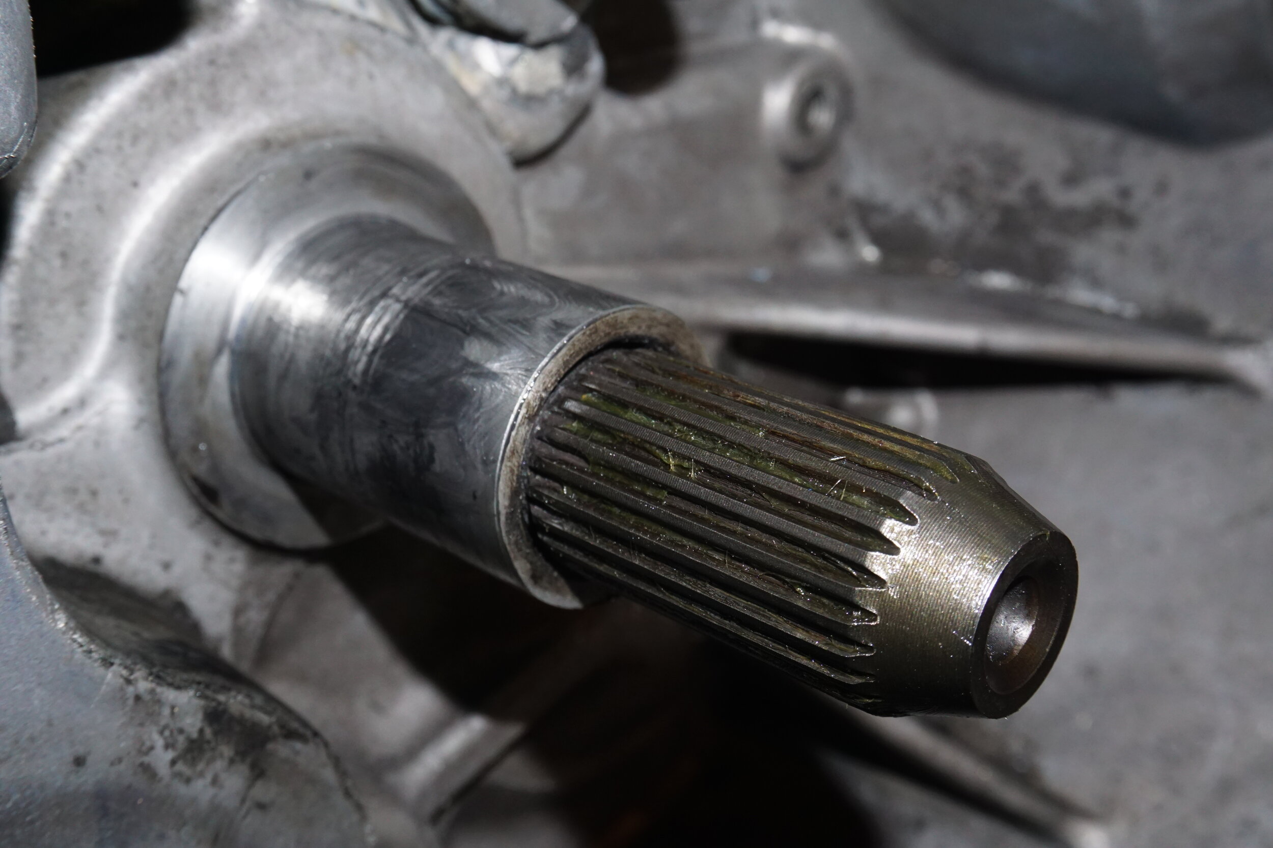
Getting the transmission in place:
I removed my crossmember when I removed the 5 speed. You will need to support the engine from the top before you remove the crossmember so the engine doesn’t fall on you. Theoretically you could support the engine oil pan with a jack stand, but that’s really not a good idea as your only means of support. Best bet is to use an Engine Traverse Bar.
I tried to use my transmission jack to get the 6 speed in place, but no matter how I oriented things, it just wouldn’t fit. Don’t waste time like me, just bench press the trans until the input shaft lines up with the hole in the crankshaft, it takes like two minutes. Be mindful of the dowel pin on the rear, it needs to line up before you start tightening bolts.
I removed the shifter cable bracket from the trans before installing it, which made getting it into place much easier.
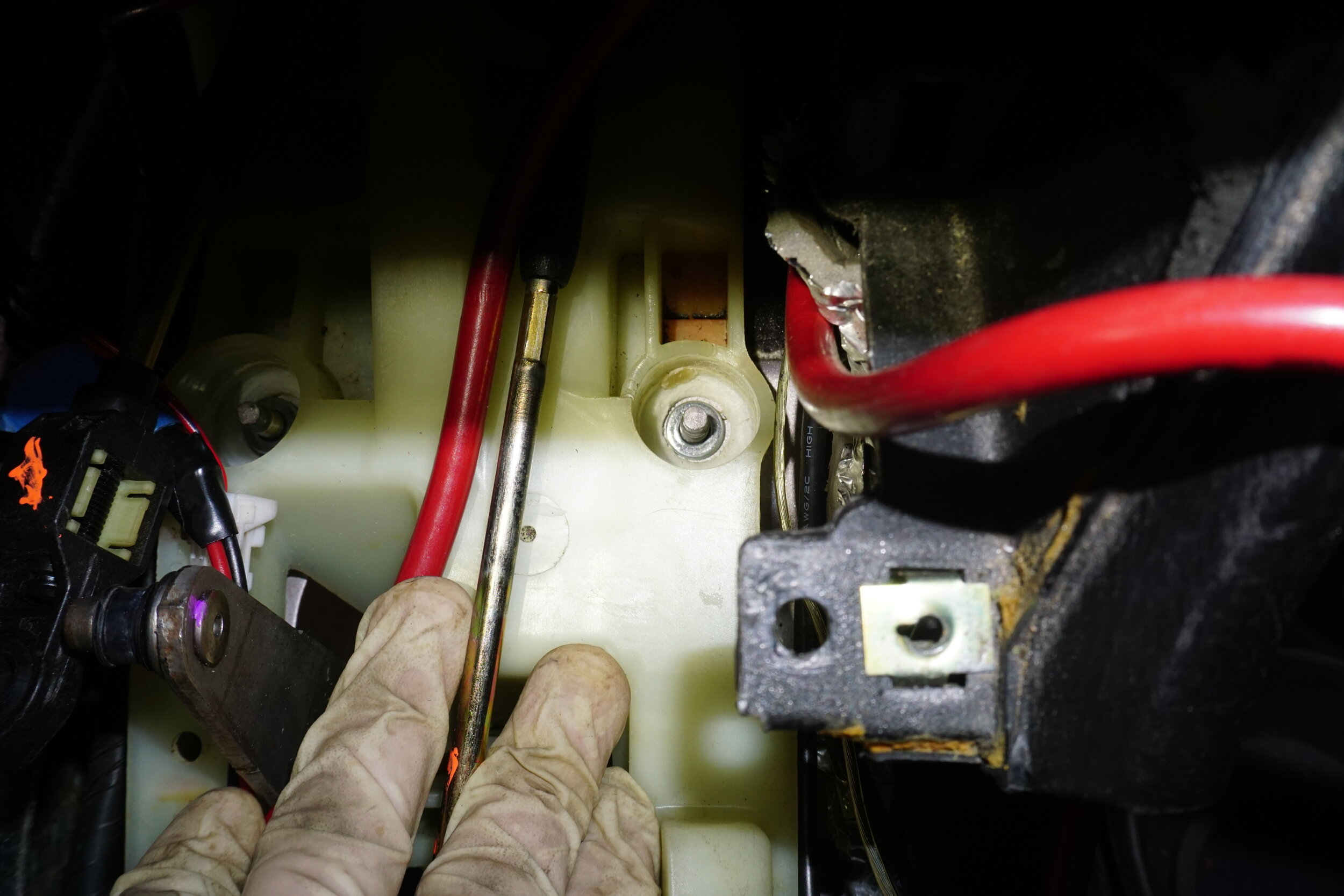
Cutting the firewall, running the shifter cables, and installing the shifter:
If you are doing this with the engine still installed, be prepared for a tight squeeze. I could not get a straight shot on the firewall to use a step bit on my drill gun to make a nice round hole, so I had to improvise. I have a flexible arm attachment for my Dremel that allows it to reach into tight areas very easily, and that’s what I used to cut my ugly, square-ish hole with reinforced cutoff wheels. I’m embarrassed by the results, but it’s what I could do with the space available. You will need to seal the hole in some way, either with sound deadening material, silver HVAC tape, or something else. When I pull my engine I plan on drilling two holes and hard mounting it to the firewall.

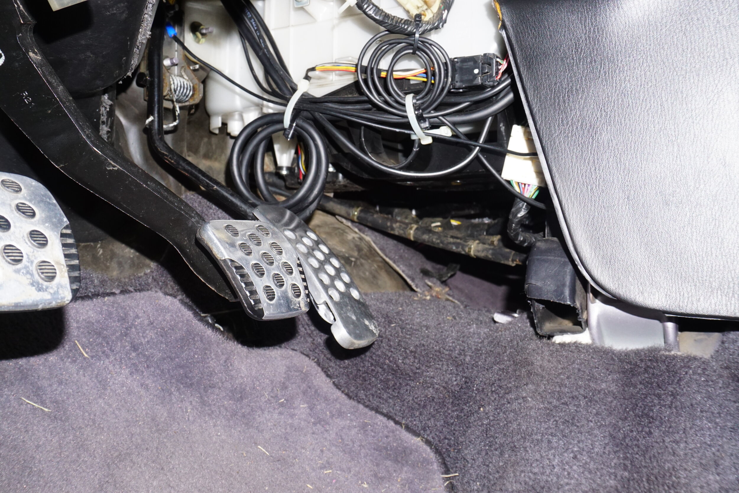
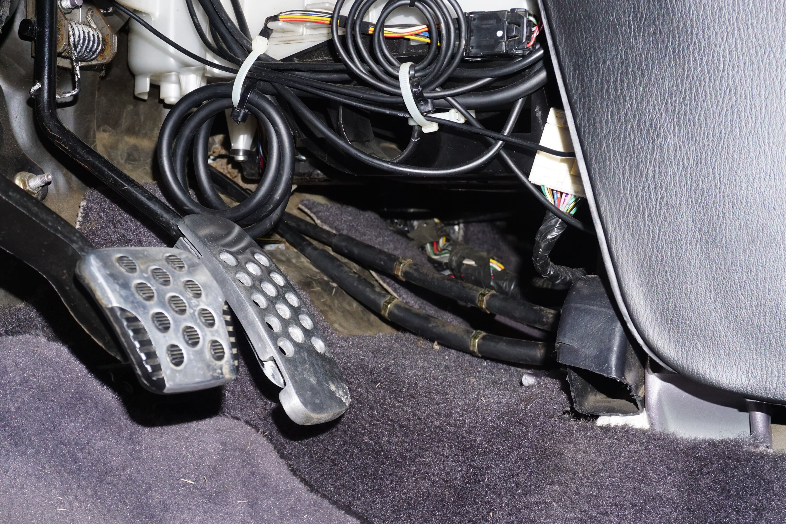
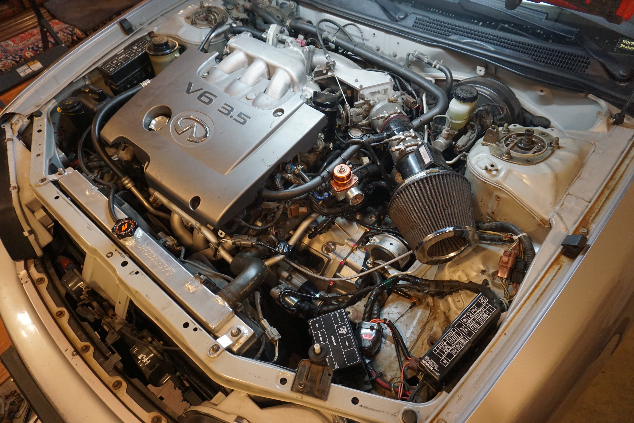
I had a hard time getting the cables into the cabin of the car. I chose to remove the ECU and the metal ECU cage from the car as I just didn’t see a way to get the cables to the shifter with them in place. This part is much easier if you have a helper guiding the cables in the car while you push from the engine bay. Get the cables roughly in place and reinstall the ECU cage and ECU. I had to fold some metal flat on top of the cage to allow the cables to go where they wanted to go since space is so limited in this area.

As for the shifter assembly, there are bushings on each of the 4 bolt holes. The two front bushings must be removed because if not, the bolts attached to the floor won’t be tall enough for nuts to thread onto. You will need 2 nuts and bolts for the back holes. I noticed that even with the front bushings removed there were very few threads for the nuts to grab onto, so I decided to grind away some of the plastic from the top and bottom of the shifter assembly around the bolts to thin the plastic out and allow the nuts to grab more threads on the studs from the body. I used an oval grinding stone on my Dremel to grind away material from the top down, and then a flap wheel on my angle grinder on the bottom. I’m guessing I removed about half of the material thickness, and this allowed me to securely install nuts. Before installing the nuts, I installed a washer or two in the hole so that the washers were level with the plastic, which I hope will prevent any movement in the shifter assembly and will also provide the best base for the nuts to clamp down on.
Regarding the shifter cables and bushings on the transmission, I used a set of 2J Racing delrin bushings instead of the stock rubber bushings. I added a couple washers above and below the bushings to bring the stack up closer to the retaining pin/clip. But the assembly needs to rotate freely, so do not stack washers too tightly against the pin/clip.

Another thing I learned was that the retaining clips that holds the shifter cables to the bracket really should be the thicker variety, rather than the thinner and flimsier version. I no longer remember which cars had which version (whether 5.5th or 6th gen), so if you only have the thinner ones, you may want to order the beefier versions from the dealer or go scrounge around in junkyards. If you can only get the thinner ones, the more important thing to note is their orientation when you install them. I initially installed one of them from the top down, but this allowed the bottom of the shifter cable to not seat fully and wasn’t flush with the bracket. Installing the clip from the side resolved the issue and the cable was properly secured against the bracket.
Thick version is in the middle:
Schmelly’s transmission bracket
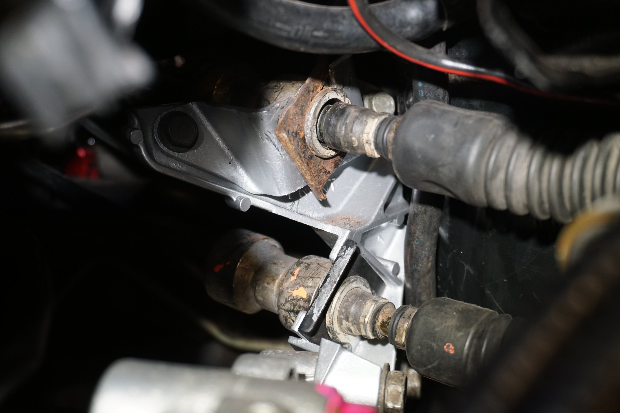
I’m writing this section something like two years after I did the install, so I’m going to gloss over a lot and possibly forget things. The bracket I got from Schmelly was a prototype, so fitment wasn’t perfect. Things may be different now, so please check with him. I basically had to grind some metal from a couple areas, nothing too serious.
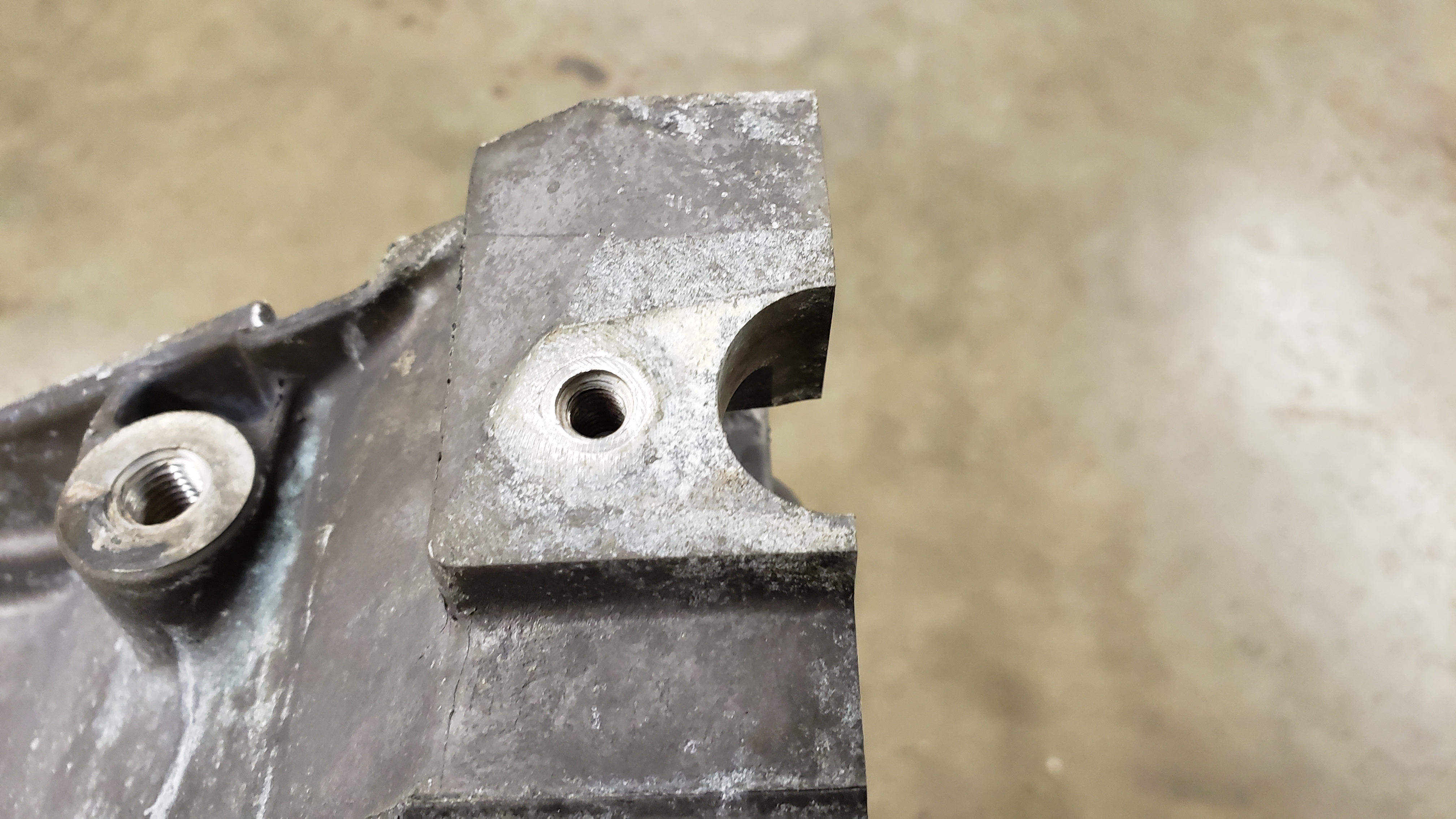
First up was a small area of the body mount, on the rear part of the mount. Do this while the transmission is still out of the car!
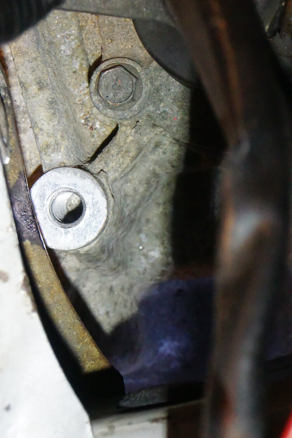
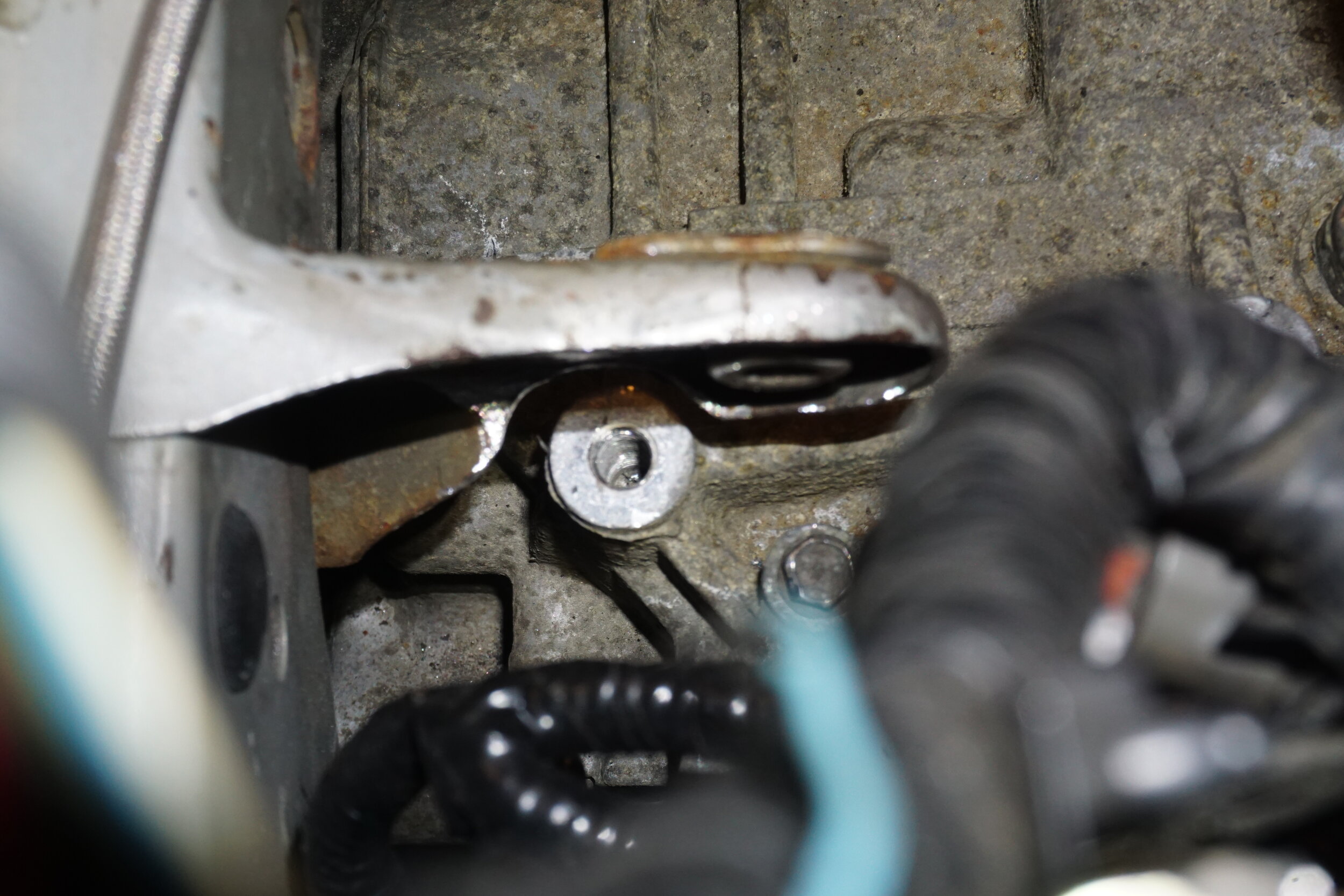
I eventually took even more metal out to make tightening up the bolt below easier.
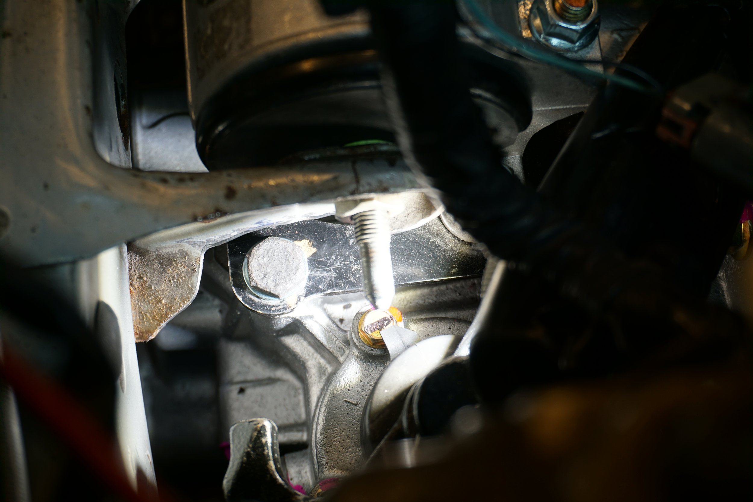
Then I had to grind a bit from the SR20 mount so the nut could sit flush, as I encountered some interference from rough casting marks.
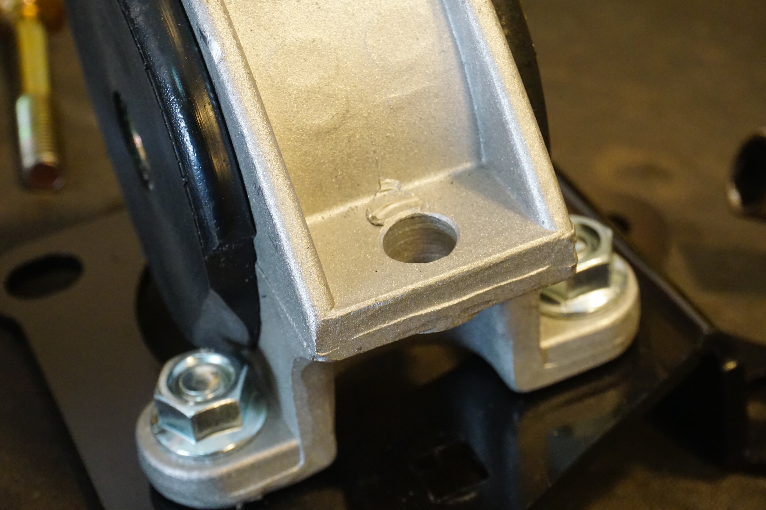
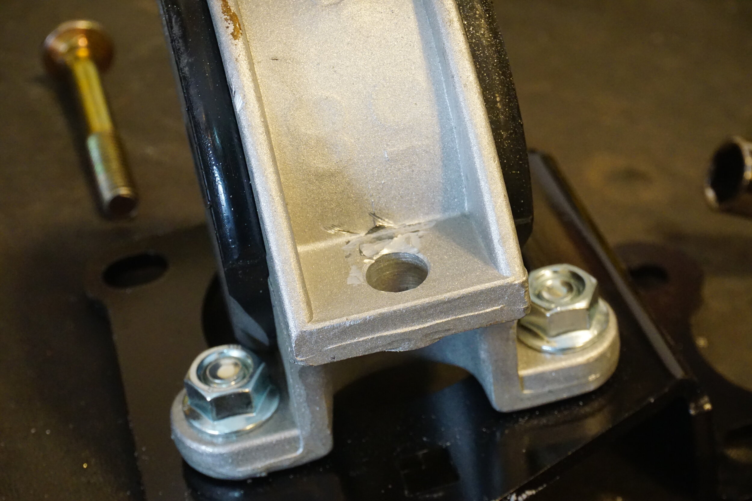
One of the bolts was too close to the Energy Suspension insert for the SR20 mount, so I shaved off some poly.
And to get the bolt/holes to line up for the mount, I had to use a pry bar between the frame and the trans to force things into alignment.
All done!
![]()