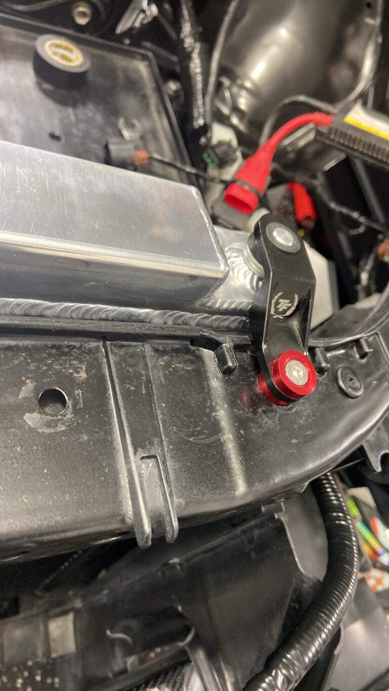
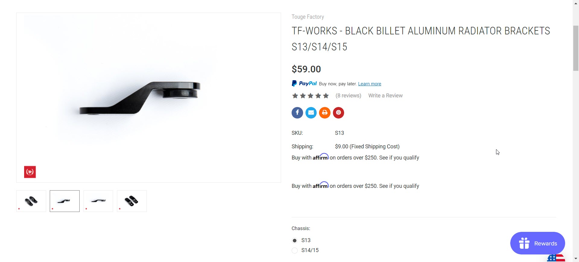
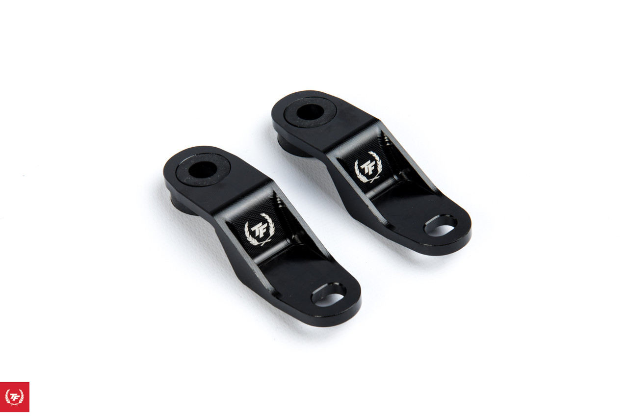
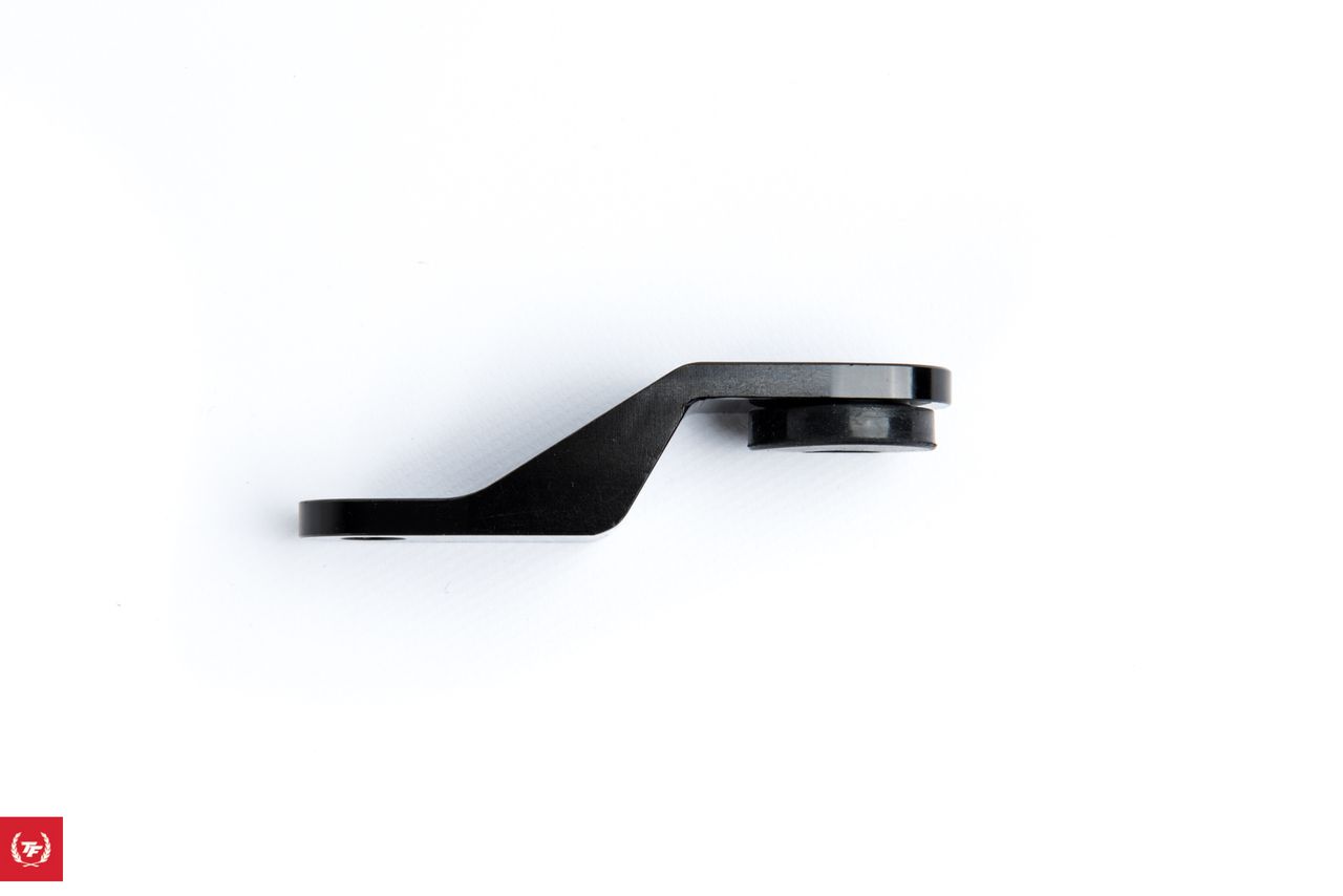
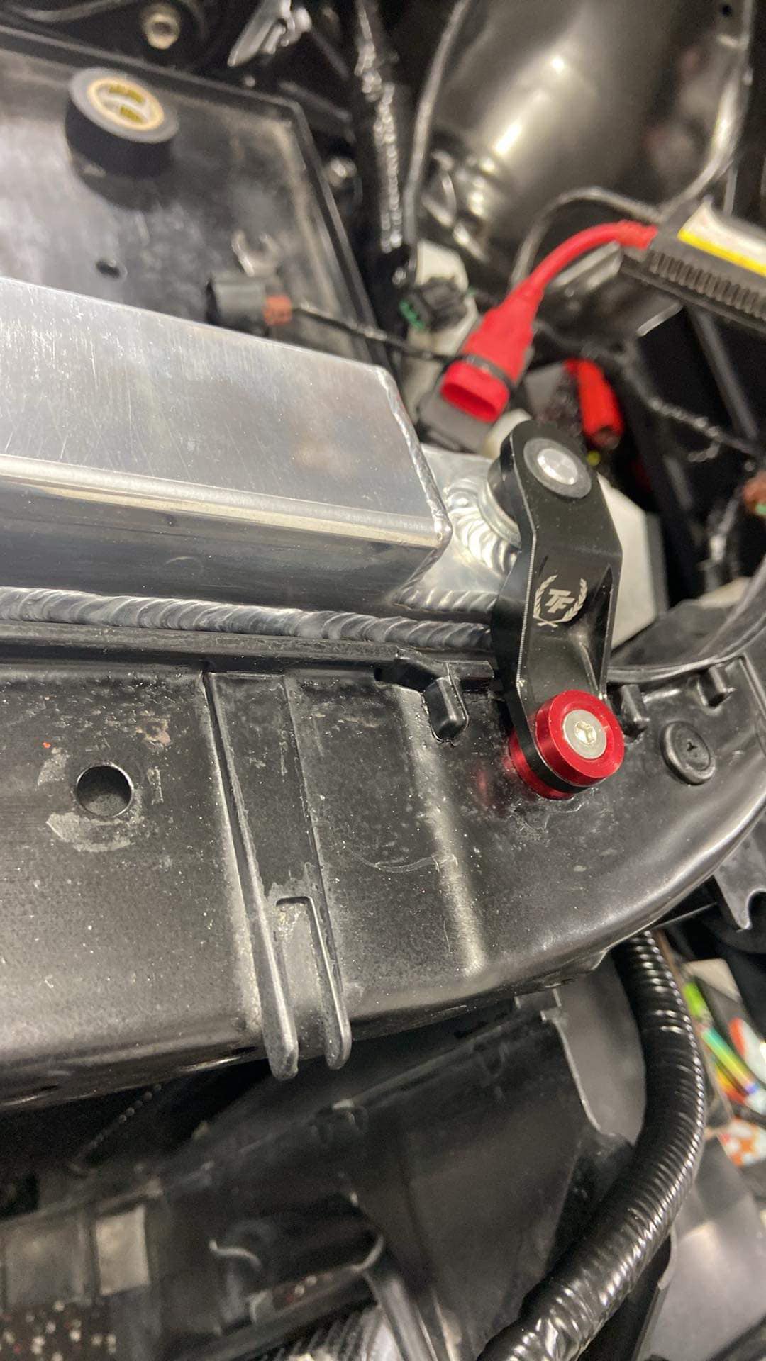
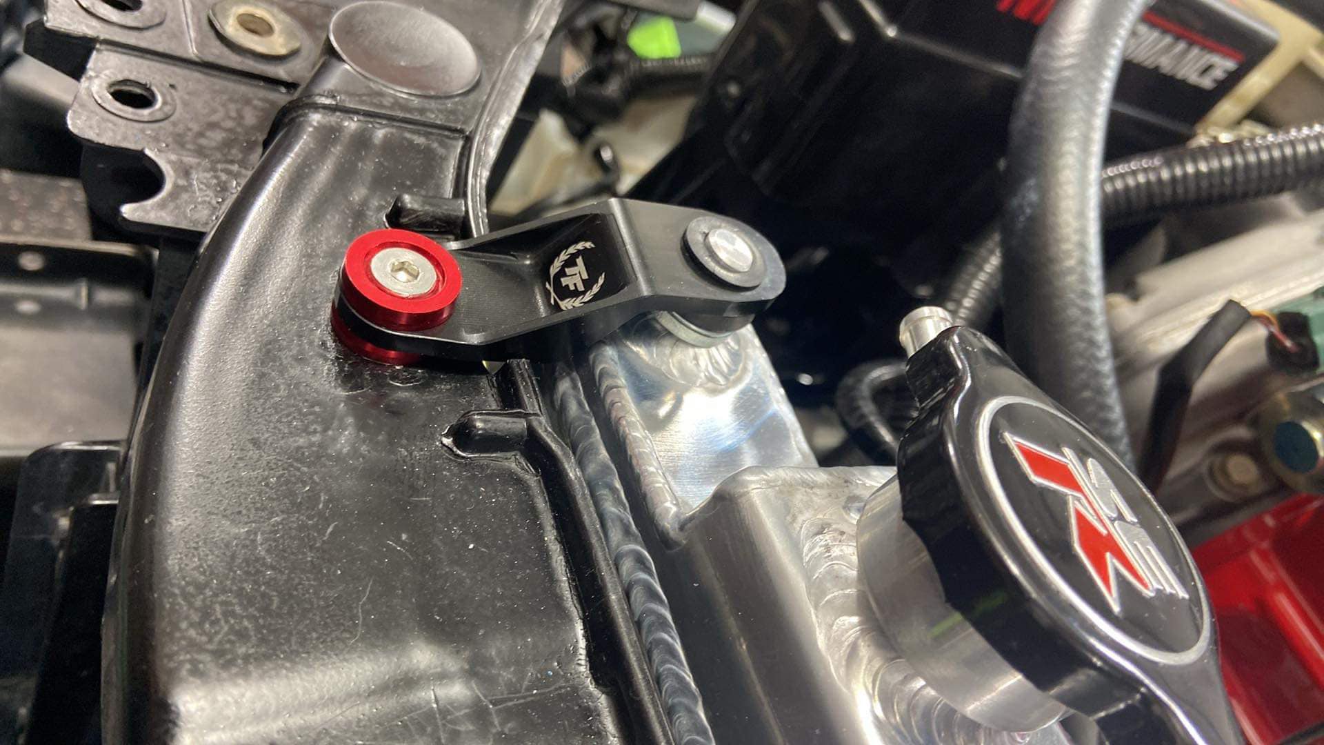
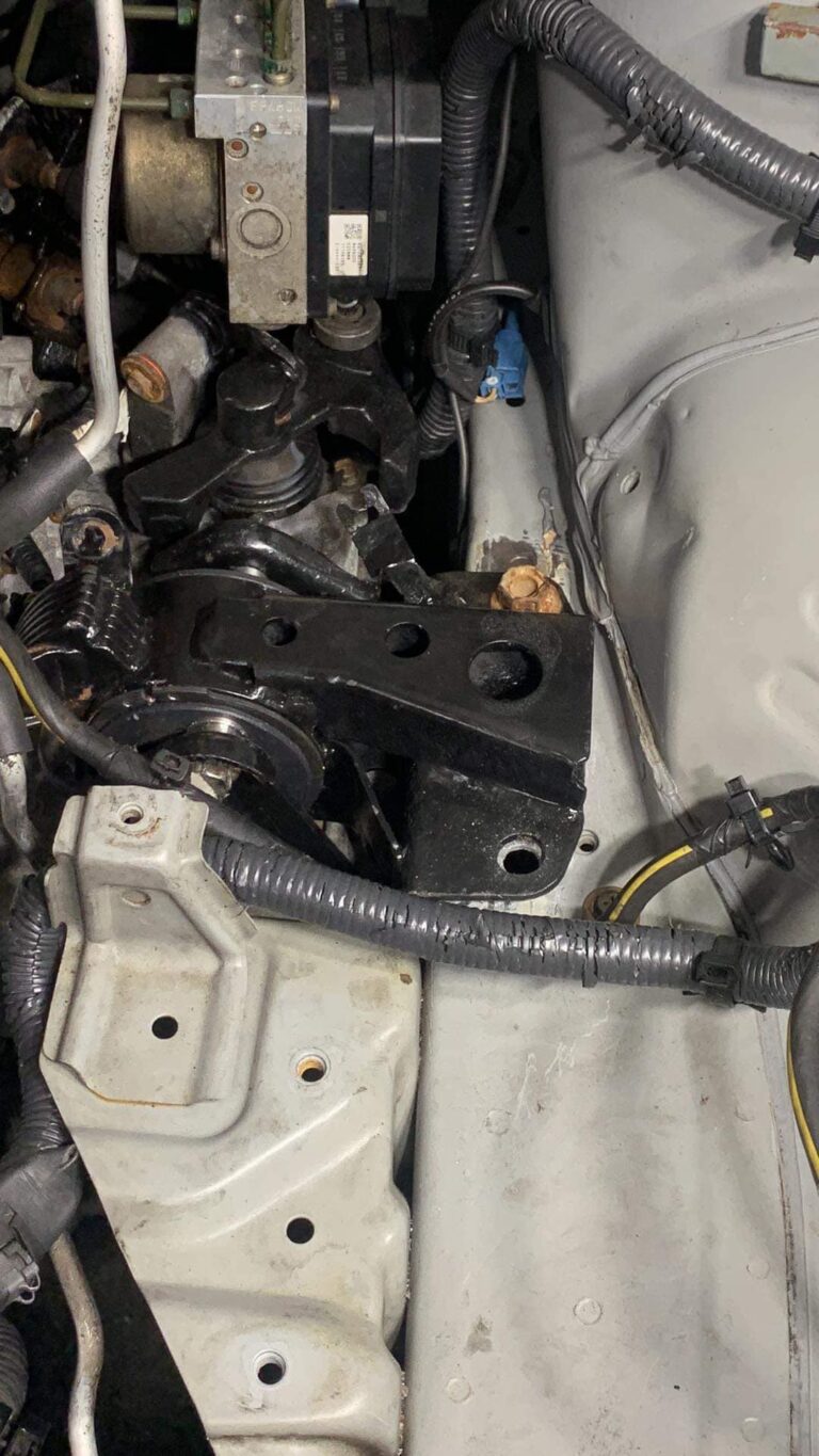
Alright so I found some radiator brackets that are way cooler than the OEM ones! Some slight modifications but they otherwise work great and look so much better than the OEM brackets!
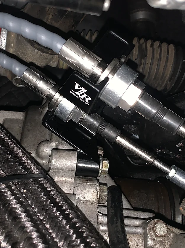
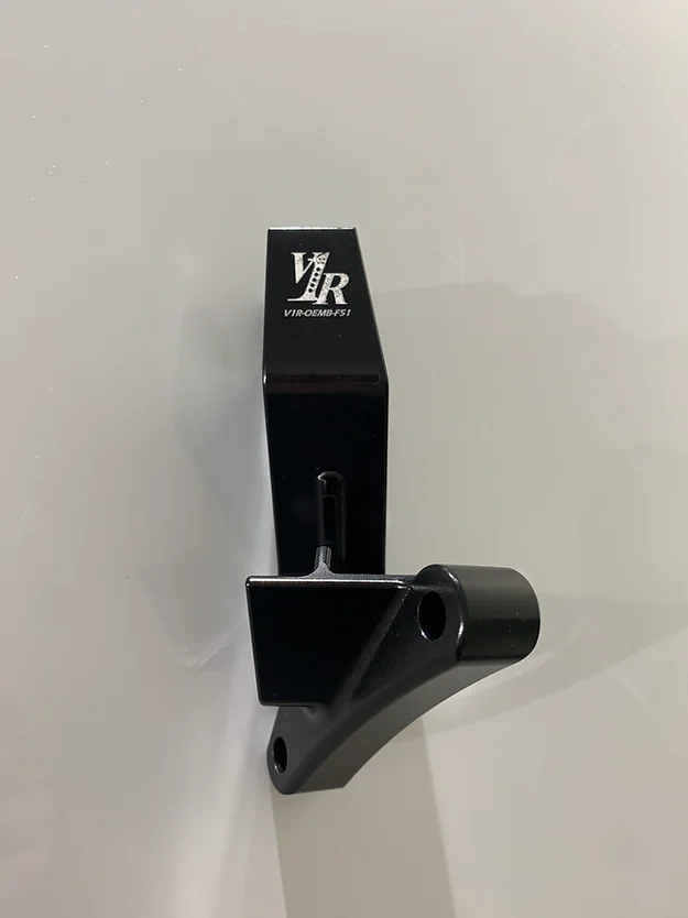
Our HD Shift Cable Bracket has been in development for a large part of past year. With a product we’re now proud to put the V1R brand on we’re excited to officially bring this to market!
Machined from 6061-T6 Billet Aluminum, this piece retains your cables in the precise factory location and orientation. Each bracket is then anodized with a Type III Hardcoat finish and capped of with our signature V1R laser etched logo.
Scavenging scrap yards for old, used brackets are a thing of the past! This is the perfect complement to the rest of our drivetrain-related lineup and is sure to be the LAST bracket you will need to buy!
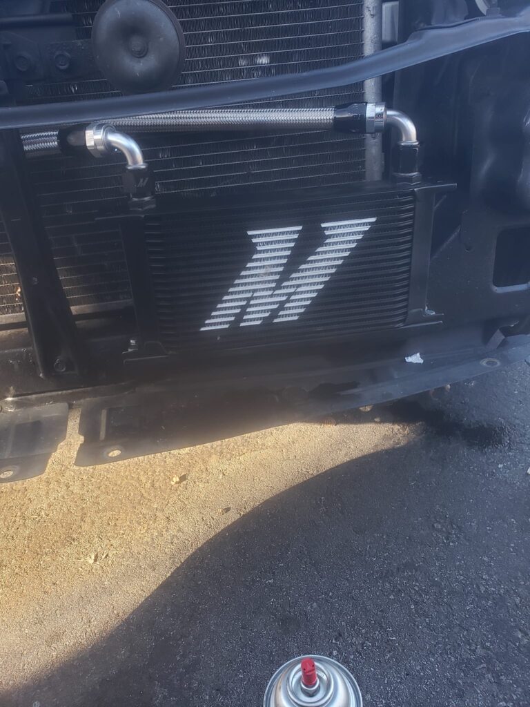
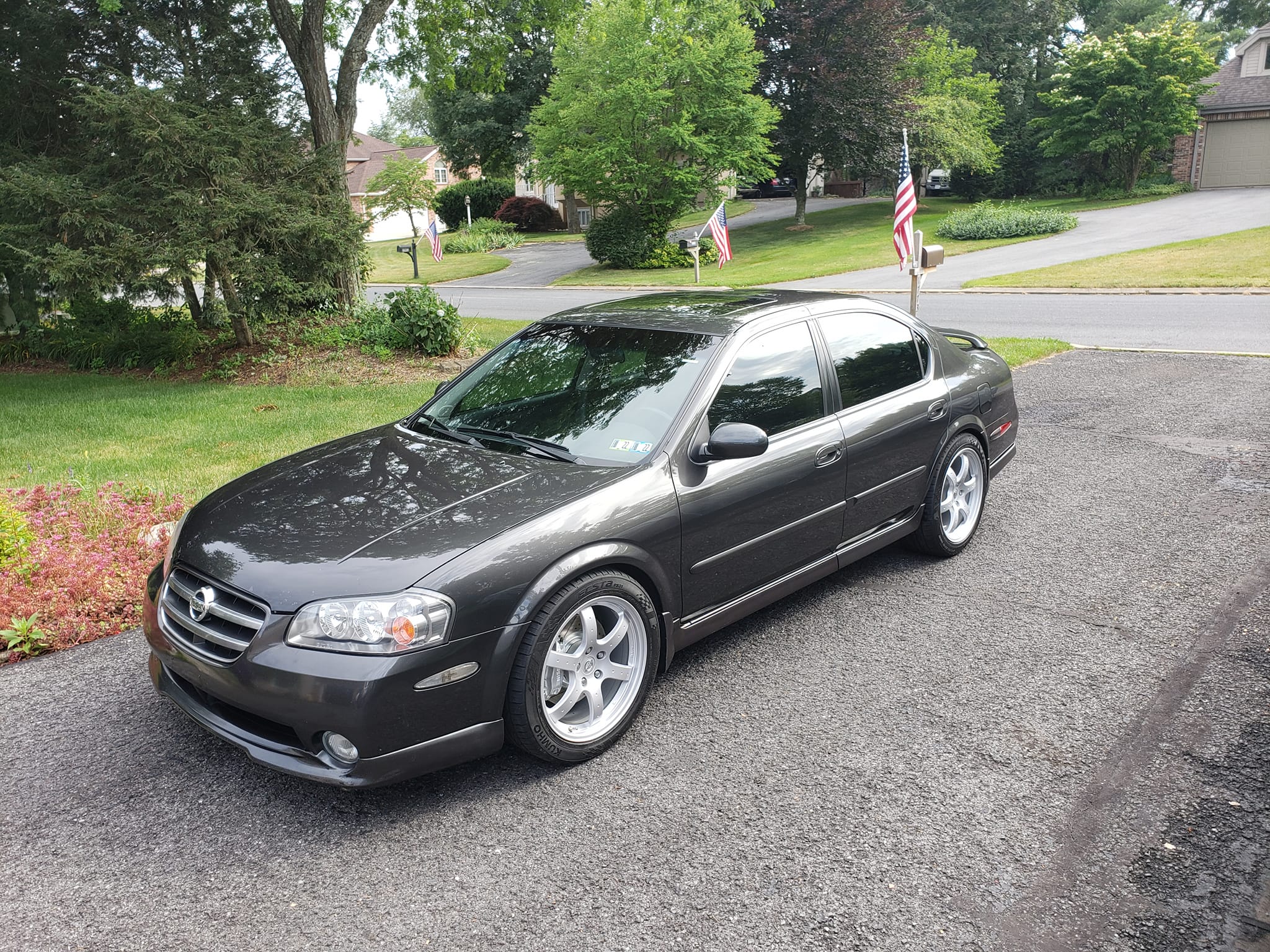
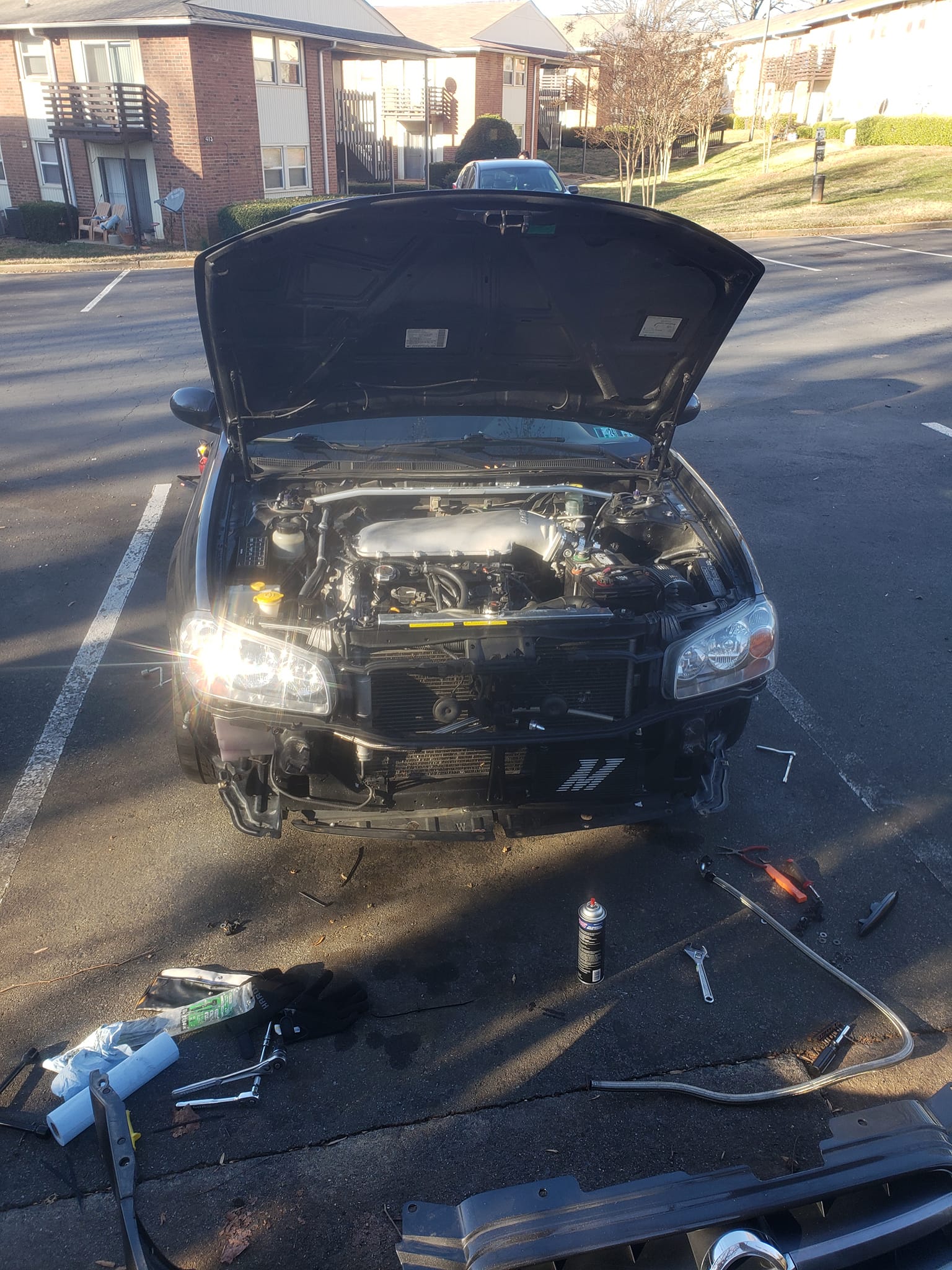
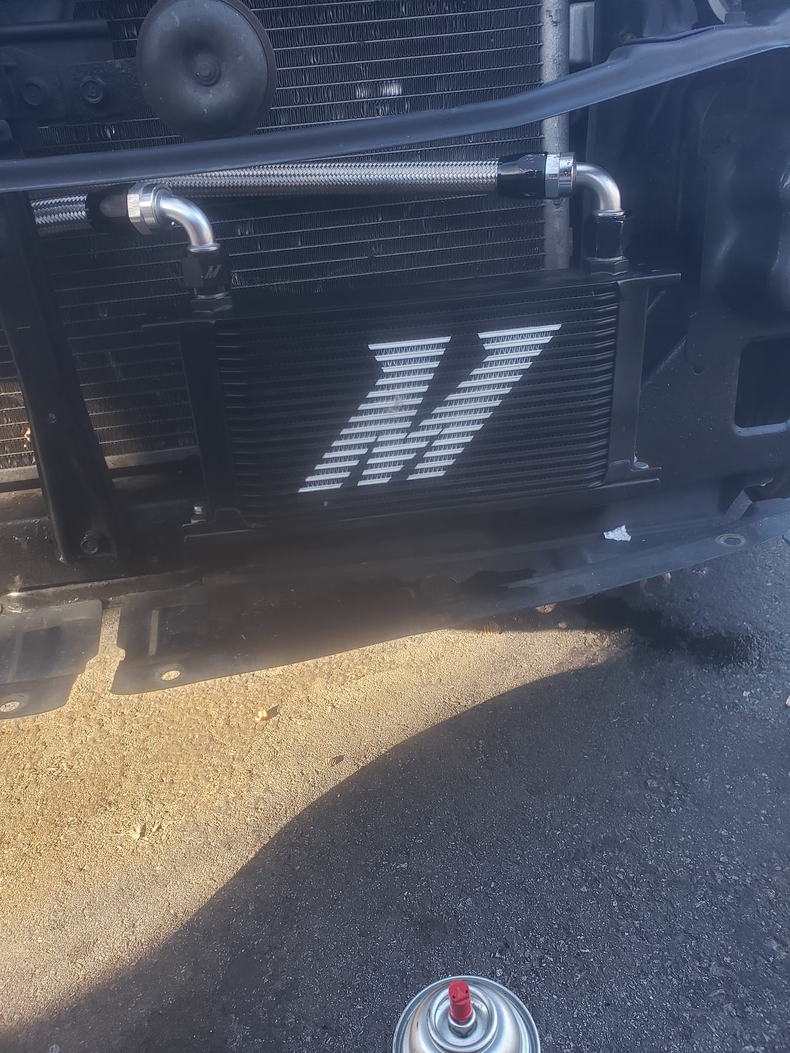
For all those wondering, you can make a Mishimoto 350z/G35 oil cooler work on a maxima! Of course there are a few modifications needed.
I cleaned up a few bolt holes already on the cross member already tapped to m6x1.0 for the bracket to bolt to. The one supplied by Mishimoto had to be redrilled for the one hole to line up.
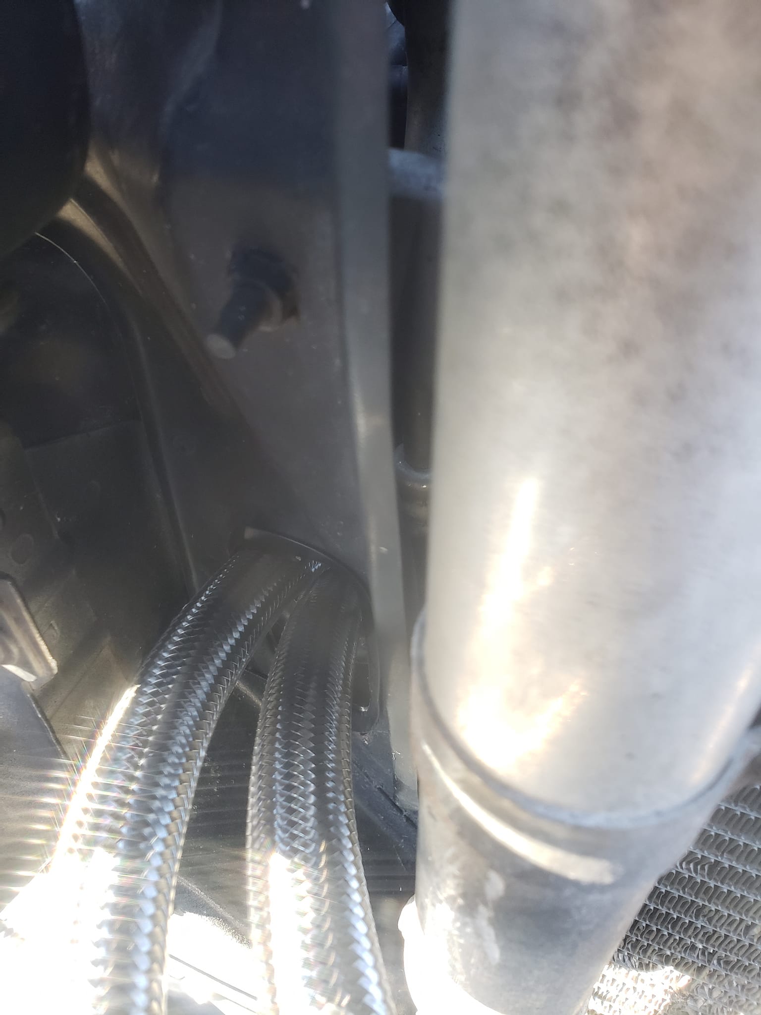
I had to use a 2″ hole saw to open up the pass through for the PS lines on the 4th gens for the -10an lines to go through. Then put some plastic door edging around the cut so it doesn’t rub through the lines.
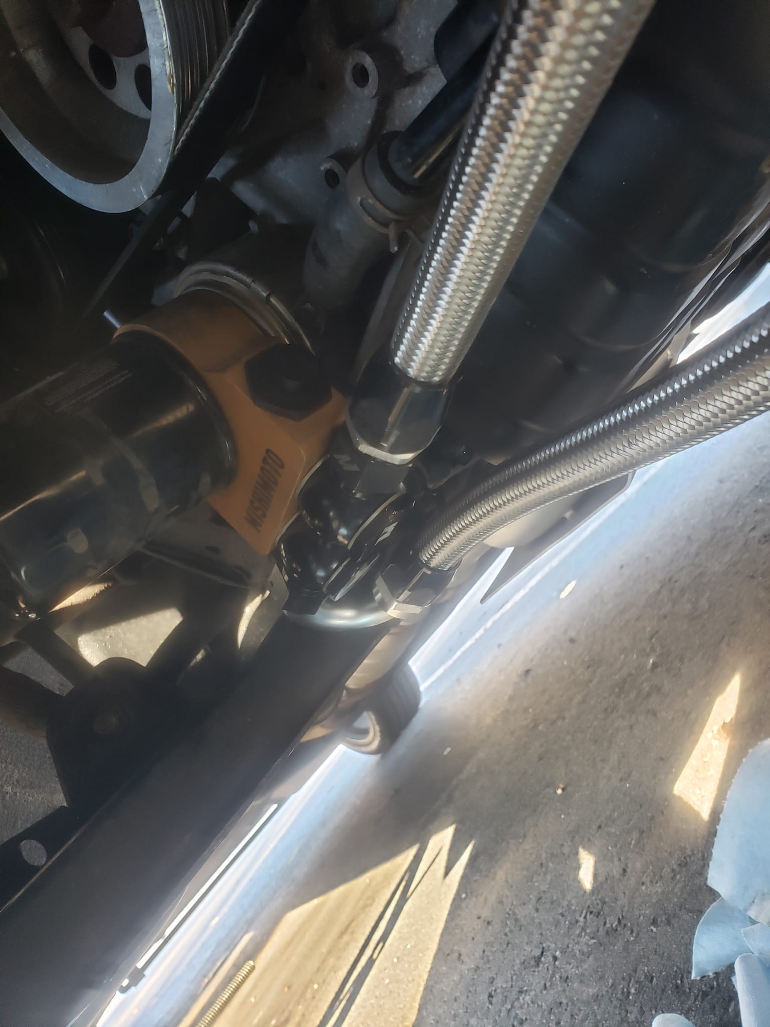
The kit comes with a 4′ and 5′ line but I needed a little bit longer line to work with the 180° fitting I purchased. While not ideal I used the 180° to get it out of the way of the tire as much as possible. The 245’s would rub it a bit with a 90° fitting when fully turned to the left. I got 6′ of -10an braided and and cut it down to 5.5′, the 4′ line worked fine
Purchase some hose separators and zip ties to keep the lines out of the way of anything dangerous. Now you’re done!
Now is this necessary? Not really, but because of the cattman designed headers I couldn’t run my extended stillen oil pan. This helps get a little more capacity to the system. I also noticed that it does seem to be working. When the car is up to temp I can put my hand on the cooler through the bumper and feel it significantly warmer than anything around it. I also opted for the thermostatic cooler since I run the car in the winter and dont want the oil to be too cold.
Gerson Flores aka GTuned Performance is now providing tuning services for Nissan Maxima and Altima using UpRev. Well-known in the Maxima community for his significant contributions to the 7th generation Maxima parts list, Gerson has been a key figure for some time. His parts list has been instrumental in over 20+ successful 7th generation 6-Speed swaps. Leveraging his extensive experience, Gerson provides optimal and safe performance tuning for your Nissan Maxima or Altima.
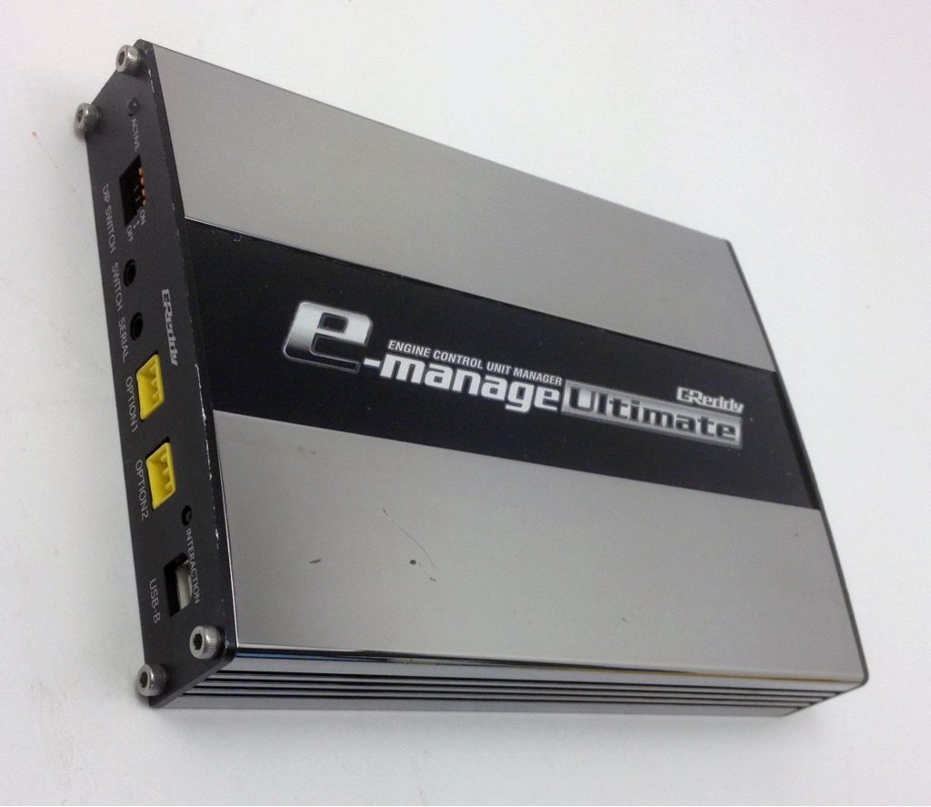
I purchased a used an E-Manage Ultimate a couple of weeks ago and I finally got everything installed and set up so I figured I should share my experience, as this is not a commonly used device for the 5.5 gen Maximas.
Install:
I used DandyMax’s write up for some other useful information, but his guide was for the A32 and 2000-2001 A33, so I had to do certain things differently. Link Below:
My Emanage actually came with a plug and play harness for the 350z/G35 and 04+ Maxima, but this was not compatible with my ECU, so I had to cut and splice every wire individually. I used a combination of heat shrink tubing and silver bearing solder.
Important Notes:
I added diodes (Radioshack rectifier diodes, the black ones) on the ignition output side of the Emanage, as it is rumored that the ignition drivers inside the Emanage leak small amounts of current, which triggers the ignition coil transistors to partially “turn on” the coils. This can fry the coils due to over heating. The voltage drop of the diodes is supposed to reduce the amount of current seepage from the ignition drivers of the Emanage. This was more common for the Emanage BLUE, but I figured that it wouldn’t hurt to do it on the Emanage Ultimate also.
As stated in DandyMax’s guide, you have the choice of running either the coolant temp sensor and the intake temp sensor, or replacing one of the temp sensors with the knock sensor. Please note if you are going to use one of the inputs for a knock sensor, set the appropriate jumper to OPEN. Not doing so will send false knock signals to the ECU. You’ll know if you are getting false knock because your car will pull about as hard as a moped.
Please note, I was not able to get the knock sensor input to show anything, even on the newest firmware (as of September 2010) version 2.20.
The autotune (AFR Target) feature will NOT work unless you have the coolant temperature sensor hooked up.
You DO NOT need to have the crank sensor input hooked up in order to advance or retard the ignition timing, it is only there to be able to show you your real time ignition timing.
Problems and Solutions:
Upon doing my first datalog, I noticed random spikes/dips of my ignition timing and RPM’s and other RPM dependent functions. If I switch the RPM Input to “Ignition Coils” instead of “Crank Sensor”, the RPM spikes went away, but the ignition timing spikes were still there (this is determined from the crank position sensor). After some research, I came to the conclusion that my crank sensor wire was getting some electromagnetic interference from the engine bay.
I thought that I could fix it by replacing the Crank sensor wire with a shielded audio cable that I had laying around. Well, this did not change anything. This ruled out interference as being the problem.
After some MORE research, I saw a post on here about how someone else was getting random ignition timing spikes and they fixed it by downgrading to FW version 1.14. I did that.
This did reduce/eliminate the random ignition timing spikes, but read on…
Fried Coil Anyone?:
After driving around for an entire day with the Emanage Ultimate hooked up, I pull into a parking lot and shut the car off. Once I get back in, I turn the key to the “ON” position and put my seatbelt on.
I start the car, and I notice that I am only running on five cylinders. I limp home and determine that my center/rear coil melted. Figures that it’s one of the coils that you can’t get to without taking the entire UIM off.
I replaced the coil with a coil from PepBoys for $70 with a lifetime warrenty.
My theory is that the coil got fried because I was running the older firmware version 1.14. I upgraded back to firmware version 2.20 and I haven’t had a problem, and it’s been two days.
This surprised me actually, as I figured that I protected myself by installing the diodes, but apparently not.
Just remember to never leave the key on the “ON” position for extended periods of time, as the small current leakage of the Emanage will heat up the coils and eventually kill them.
Timing Advance (Or Not):
Once I got everything situated, I decided to do some logs to see where my timing was at.
I tried adding some timing here and there, to bring my total curve average to around 24 degrees, approaching 28 as it gets closer to redline.
Well, I was able to add about 3 degrees until I noticed that for each extra degree that I added, the timing in that area ACTUALLY WENT DOWN. This was because the ECU was pulling timing because of “knock”.
I was running 93 Octane gas and I was only at like 23-24 degrees of timing and I was getting knock. This can’t be right because I’ve seen VQ30’s run much higher timing (28-30 degrees) and the VQ35 is supposed to be less prone to knock.
It appears as if the 2002-2003 ECU is much more sensitive to knock input from the knock sensor.
I temporarily bypassed the knock sensor by putting a 470k Ohm resistor in its place and I was successfully able to advance my timing to around 25-26 in the low end (1000-4000rpm), 23-24 in the midrange(4000-5000, torque peak), and 27-28 in the high end (5000-6600).
I did advance it too far at one point and I was able to actually HEAR the knock so I immediately stopped and retarded some timing. It is extremely important if you are going to do this, to do all your pulls with the windows down so you can hear any potential knocking.
At this point, I am researching ways to reduce the sensitivity of the knock sensor. I am thinking about putting some sort of rubber bushing under it to muffle some of the noises that it “hears”. I will report back with results. I don’t really feel comfortable driving around with no knock sensor. If I can at least get SOME knock protection, that would be great.
AFR Tuning:
I am using an Innovate LC-1 wideband to monitor my air fuel ratio. I did not want to buy the Greddy Option port harness for $20, so I made my own. I used one of the old cables for the audio port of a CD ROM drive in a computer (not the ide cable, the 4 pin little audio cable). I grinded the connector down so it would fit. Remember that the ground is the pin closest to the option 2 port. The positive is the pin on the opposite side.
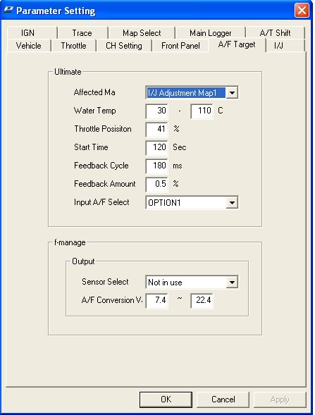
I set the AFR Target settings to activate above 41% throttle. I left the feedback cycle and amount alone.
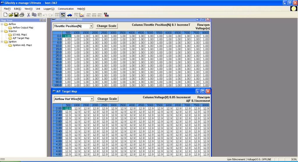
The target AFR map is 12.9 everywhere.
I plan on leaving this on all the time, which I heard is bad but I don’t care, as it gives me perfect 12.6-13.2 AFR’s in every gear at every RPM.
Coolant Temp Problem:
I noticed that my car never quite heats all the way up. This causes the idle to remain high. I think this is due to JP13 being set to “1-2”. I will switch this to “open” tomorrow and report back.
Blown E-Manage (October 2010 Update):
Well, I did the above (about switching the jumper setting for the coolant problem), and I fried my E-Manage! Within five minutes of the car running, after I switched the jumper, it stalled out and the E-Manage’s green power LED would not come on. This is believed to be because when jumper 13 is set to open, it is expecting a knock sensor input, which is a lower voltage than a coolant temp sensor.
DO NOT RUN THE E-MANAGE WITH JP13 SET TO OPEN IF YOU HAVE A 5.5 GEN! In DandyMax’s guide, it states to try switching the jumper settings if you are having problems with your coolant temperature reading correctly, which I was, but his guide is for the 4th and 5th gen Maxima, not the 5.5 gen , which has a different coolant temperature sensor.
I had to purchase another E-Manage unit. This time I did something different. Read on…
Tricking the E-Manage:
I needed a way for the E-Manage to think that the car was warmed up so that the Autotune feature would work, but I had no way to properly hook up the coolant temperature sensor from the car. If I hooked it up with JP13 set to 1-2, it interferes with the signal and causes the car to think that it is cooler than it is, and when I switched the jumper to OPEN, I fried the E-Manage.
So, I discovered that when fully warm, the car’s temperature sensor sends out ~1.00 volts. I connected the AIRFLOW VOLTAGE OUT of the E-Manage to the WATER TEMP IN on the E-Manage. Then, I configured the E-Manage’s airflow correction map to output a constant 1 volt signal at all RPM ranges. This is with JP13 set to 1-2.
I am basically using the E-Manage to send out a constant 1 volt signal to itself, to trick it into thinking that the car is always warm. Now I don’t have to have my coolant temperature sensor connected to my E-Manage at all.
Screen Shots:
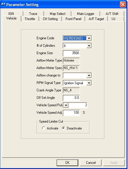
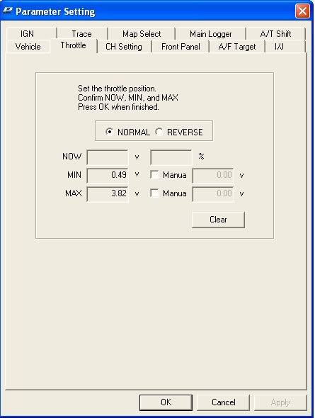
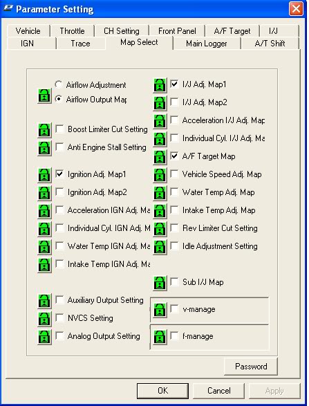
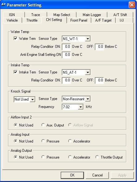
Parameter settings.
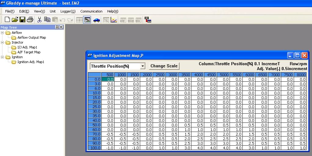
My ignition adjustment map. (Don’t just copy mine, as every car responds differently to ignition advance)
Screen shot showing the airflow adjustment map and my AFR target map.
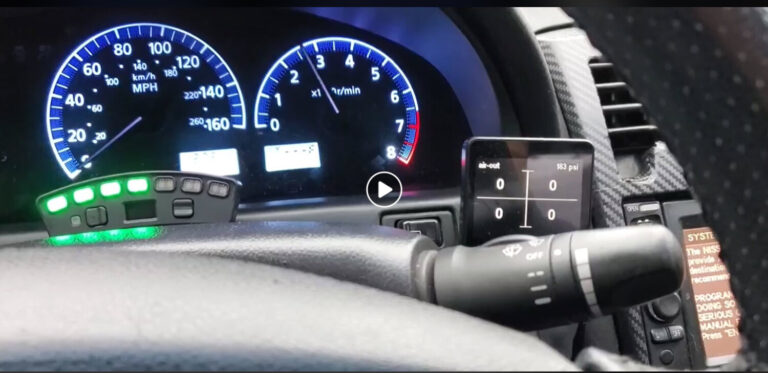
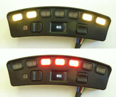
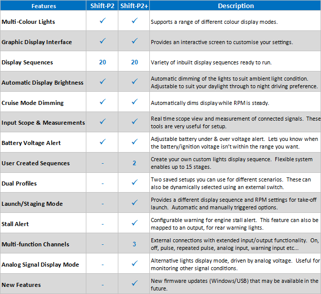
I wanted to add a sequential shift light to my 2002 Nissan Maxima. After doing some research, I decided to go with the Ecliptech Shift-P2 Shift Light Light. Pretty simple and straightforward to install. I ordered it from the link below and these guys shipped it out super-fast. Would recommend ordering from them if you choose to go this route. It was super easy to install as well.
You get smooth and consistent anticipation of your shift point.
It reduces driver workload and fatigue, both in sprint races and endurance events.
It provides drivers with reference points for performance.
You can achieve consistent staging RPM for standing starts & launches – so no more watching the tacho on the start line!
In enduro events, you can manage your fuel by short-shifting at an indicated point below the peak RPM.
You can improve your lap time consistency and get up to speed at new tracks and with new suspension setups faster.
Eliminate unnecessary engine/transmission wear by keeping the RPM within the range you want, without bouncing off the limiter.
A good progressive RPM display can give you what you don’t have… a gauge in your peripheral vision showing the range of RPM you’re interested in! It gives you a reference for improving performance and building on skills. For example, maintaining staging RPM while concentrating on race start, smooth anticipated shift points and maintaining corner entry pace.
This is a great alternative to replacing your 6-speed knob on your Nissan Maxima. The original knobs are discontinued and no longer available. If you do find them brand new, the pricing is usually over $200. The GTR R34 is the same and will work great. It’s only $30 bucks more than the original pricing of the 2002-2006 6-speed shift knob. You’ll also require an adapter to convert M12 thread to M10, which is available for under $10.00. Additionally, we suggest using Permatex 25210 High Strength Removable Threadlocker.
OEM Part Number: 32865-AA420
Original Price: $160.00 to $180.00
I promised I would do this, and here it is ages later lol. This is a write up on swapping an auto 5.5 Max to a 6spd. It’s off my memory and old posts, so I will add stuff as I remember. All pictures are on the bottom!
Parts Needed:
First thing is first, you will need all of the parts to complete the swap before even reading this. There are a few good posts on the Org which cover this. Basics of course are the transmission, shifter assembly and cables, manual trans mount, flywheel and clutch, clutch pedal spacer, clutch pedal itself, and a few other misc things I will add as I think of them. You DO NOT need to swap engine wiring harnesses. If you want to, go ahead, but Nisformance actually recommends not swapping any harnesses or computers.
Onto the process itself- I found myself a donor car, so my first order of business was breaking that car down for all of the parts- this makes things easier.
Installation Steps:
Step 1. Obviously, you need to cut loose all of the parts from your auto. This includes; The brake pedal, the transmission, the shifter and it’s cable, and cutting off the automatic trans mount. I only cut it on the side of the frame rail, no need to cut the top off, it assists with the strength of the metal.
Step 2. Possibly one of the harder parts of this job for me was mounting the master clutch cylinder. On my car, I had a patch in the firewall insulation on my auto car, but no holes in the firewall itself. What I did was mount the patch piece up to my donor car, and drew a couple holes. I then taped the piece onto my firewall and drilled two holes, followed by the large middle hole for the cylinder itself.
Do not worry about having the best accuracy here, the clutch pedal itself has two bolts under the dash. But please, TAKE YOUR TIME with this. The more precise you are, the better. When installing the clutch pedal and cylinder, be sure to install the spacer in between the firewall and pedal, there are spacers out there, but might not be any new ones left so you may have to get creative. Also install the brake pedal from the manual car while you are down there. Okay, now that your clutch pedal and master cylinder are attached, you can proceed to step 3.
Step 3. Mount your shifter assembly and route the cables through your firewall. What I had to do was cut the bracket that covers the opening a bit, and then I was able to make it work. Use Dynamat to cover the hole, or whatever your creative brain desires. You will have to find two bolts that fit through the trans tunnel as the studs the auto used, no longer exist.
IMPORTANT: Use loctite and lock washers, otherwise you will lose your bolts.
At this point, you should have the pedal/cylinder mounted as well as the shifter, that’s a good bit. You can now install your flywheel and clutch, see other posts for torque specs until I post them.
Step 4. Put the transmission in. This takes a lot of time and patience, esp if you have raised motor mounts. You can look up tips and vids on installing it. As far as mounting the bracket, there’s a couple options here. You can weld it on, or run two bolts through the top like I did. I wanted the part to be removable so pick your poison. This mount doesn’t really hold the motor/trans up, just keeps it all tight and straight when driving hard. Install your MANUAL transmission axles.
Step 5. It’s now time for wiring, this is easy, even for me who hates wiring. So you will see a few methods on wiring the car so that it cranks over. You do as you please, multiple methods work!!! But I suggest to wire it like a factory car. To do this, you will need to have the REAR connector off the clutch pedal. Take one wire and ground it, and the other wire needs to go to the INHIBIT relay in the relay box in front of the battery. You will be tapping into the
Green/Orange wire with the wire off the clutch pedal. This allows the car to function as it came from the factory, it will not crank without the clutch pedal depressed. Now you have to wire the starter. The automatic starter has the connector you need. Cut it off (as well as the one off the manual starter) and attach the auto connector to the manual starter.
You can now connect your shift cables to the trans, one piece clutch line to the slave cylinder (bleed it of course), and you should be ready to start the car.
Reverse lights also need to be wired up
Step 6. Wire in the reverse lights. On the auto harness, you will see 3 connectors that don’t plug into anything. The bigger of the 3 is what you use. Take the Green/White wire and put it to the green/white wire on the manual trans. Same for the Orange wire (I believe the orange wire you want is the one further from the green/white wire, I will update when I can). I cant remember off the top of my head which orange and which green/white to use. There’s two of each, so just experiment a bit. I can update this when I’m with the car again and have a picture.
At this point you should have a manual transmission car! This is the major steps, of course there are other components such as filling the trans with the PROPER oil, swapping clusters if you don’t want to see the auto gear letters, putting a manual trans shift bezel on, etc…