Tag

Engine Bay Mods

Browsing

Community Member Credit: CMax03

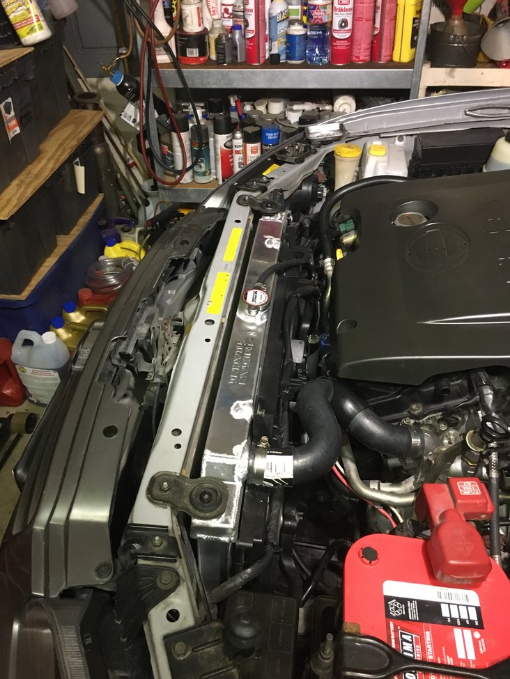
I’ve installed the Megan Racing Radiator and I love it! It’s 1-7/16” thick core versus the OEM 1” thick core. No drain! So what, it has a lower radiator hose. Everything fit the only minor issue is the upper support pegs are slightly lower than OEM & the filler cap is slightly to the right causing the overflow hose to have a little less slack. That’s it fan shroud is closer to my Cattman Headers but they’re ceramic coated so and they don’t really radiate that much heat so applying some of that thermal barrier tape might be a good idea. Function tested it and it works great!

Side by side view with OEM radiator.

Reference Info by SquidBeak

Thanks for the follow up wellshii19.

CMax03, perfect timing! Thanks for the info and the pics. Looks great!

I know it’s overkill, but I really wanted a drain plug. So I bought a bung, drilled the bottom of the radiator then had a local guy weld it in. Then I got an aluminum elbow, plug and a pvc valve for draining. Now, it’s pretty slick. I’m going to do the install this week.

I did a test to see how everything would work this afternoon and I think it’s going to be nice. I was surprised to see that the Megan radiator only holds 1 gallon. I thought it would hold more. I think the original radiator only holds about a gallon also, but I’m not positive about that.

I just finished installing the radiator. Overall, I’m pretty happy with it.
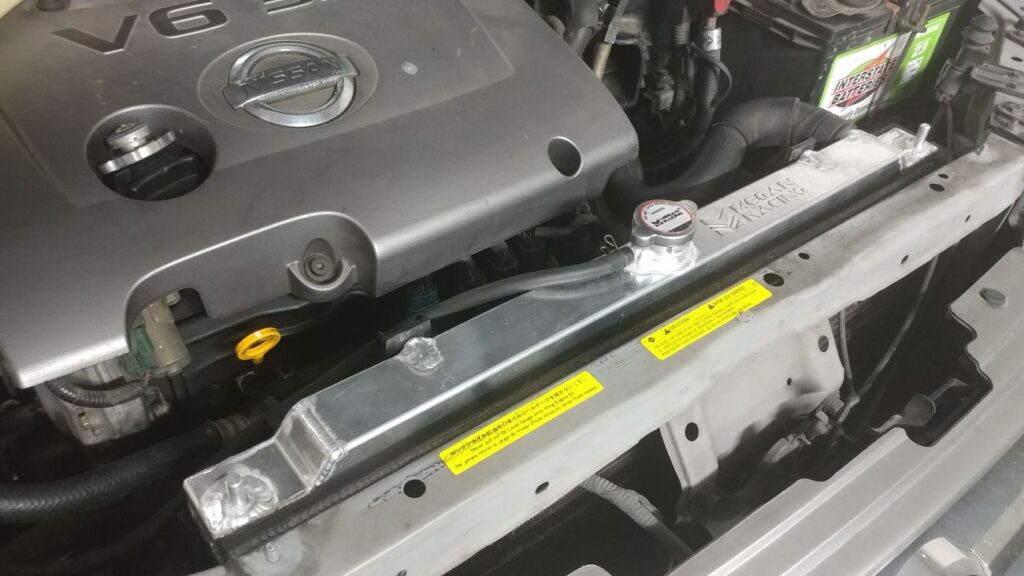
Here are some observations I made in the process:

1. I wasn’t very impressed with the AN6-5/16 barb fittings that came with the radiator. They looked like leaks waiting to happen so I used some nicer aluminum fittings. Add 5-10 HP minimum per fitting.

2. I had to file down the welds on one of the fan brackets to allow the fan shroud to fit. Not a big deal. Add 1-2 ponies due to weight savings.
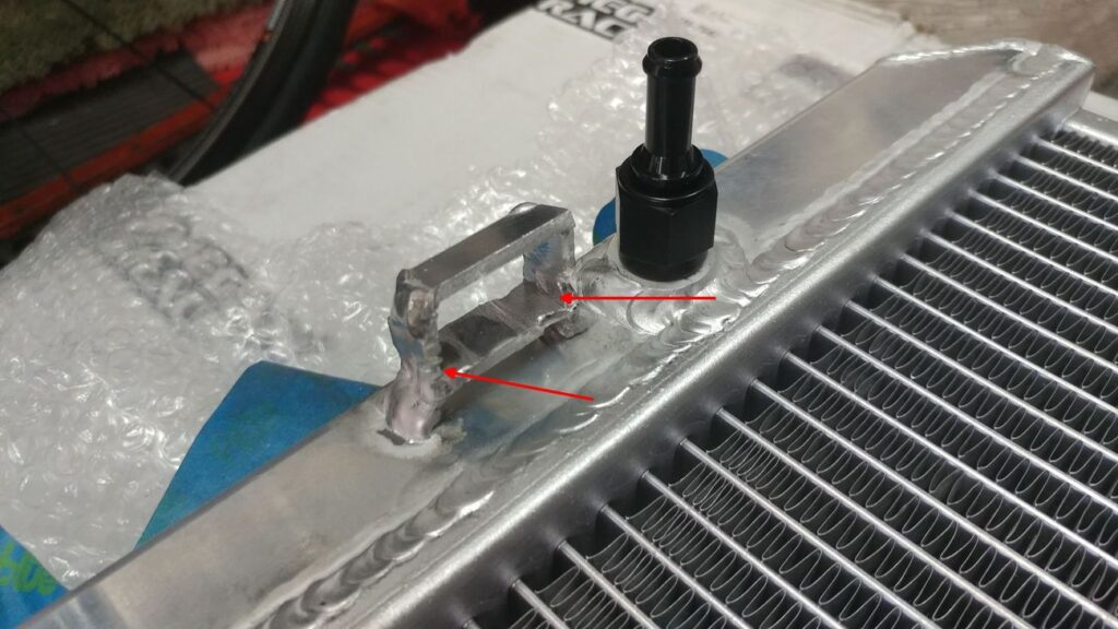
3. The 2 screws that hold the fan shroud on the original radiator thread into plastic and are basically sheet metal screws. You can’t reuse these screws, you will have to get some M6 x 1.0 screws for the new radiator. These cool red screws easily freed up 15 ponies each.
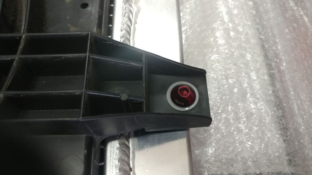
4. The drain plug made the 7-8 drain & fills much easier. Really too bad they didn’t include one. The plug was good for at least 15-20 ponies.

5. This is the most important. The original radiator cap is rated at .9 bar (13 psi). The Megan cap is 1.1 bar (16 psi). With the Megan cap there was no exchange between the radiator and the reservoir at all. None, no fluid nor air. I decided to re-use the original cap and this restored the function of the reservoir. -10 ponies for reusing old cap.

6. I decided to dissect the old radiator mainly because I was curious to see how the trans cooler works. I thought it would be just an aluminum pipe immersed in engine coolant. However, it’s actually a pretty ingenious design. It’s a hollow cylinder that the ATF flows through. This allows coolant to cool the inside and outside of the cylinder. I looked inside the Megan radiator with a scope and it has the same design.
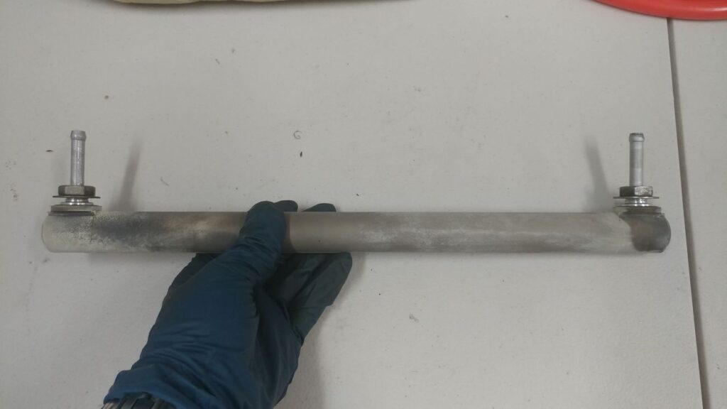
Original ATF cooler.
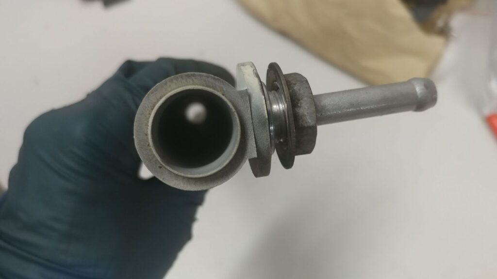
ATF Cooler side view.
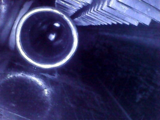
Megan ATF cooler

7. I did the intake manifold coolant bypass while I had the old radiator out. When I pulled one of the hoses off, some black liquid came out. This is strange because all of the coolant looked immaculate when I flushed it. No idea how this could happen. Any ideas? I blew out the coolant lines in the manifold with compressed air then looped one of the spare hoses to the other port of the manifold to plug them both.

8. During a 30 mile test drive, I noticed that the coolant temps now range between 190 and 208. Previously, it was 195-205. It probably doesn’t mean much, but it’s interesting.

9. Easily 50-60 HP gained on the butt dyno. Easily. Probably way more. WAY MORE. Definitely.

Loading

Community Member Credit: asand1 / maxima_se007

Important Note: This should really be used as a temporary solution. The proper fix is to replace either the knock sensor itself or the harness which is known to go bad. Most people do both at the same time.

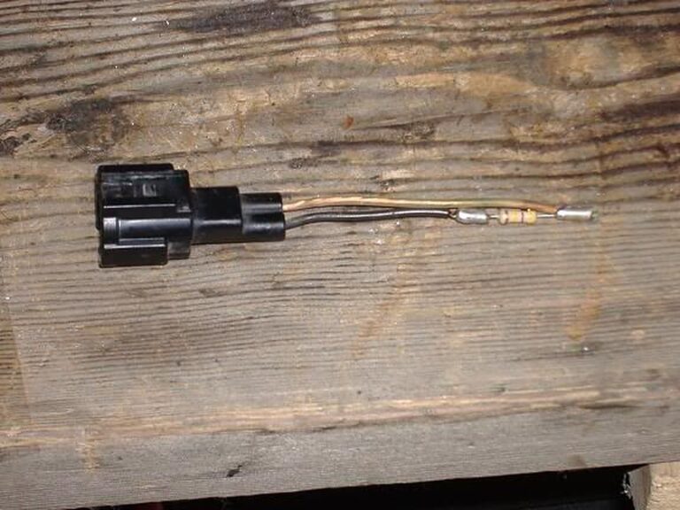
Resistor: 470K

Order Link: https://www.radioshack.com/products/radioshack-470k-ohm-1-2w-5-carbon-film-resistor-pk-5?variant=20332249541


Instructions

  1. Disconnect the knock sensor at the easily accessible connector. (you can find this by looking at the knock sensor and following the wire and wire loom towards the engine bay.)
  2. Buy a package of 5 one megohm resistors at radio shack for $0.99. (Part #: 271-1134)
  3. Take 2 of the resistors out and put them next to each other (side by side) and twist one wire on each resistor onto the one next to it from the other resistor. You now have a 500k resistor. (you can buy a 470k resistor, but i felt this would give truer results to knock sensor specs seeing as how a good knock sensor is between 500k-600k ohms.) DO NOT twist only one side, creating a 2000k ohm resistor (by going —(***)-x-(***)— (imagine the —(***)— is a resistor and x is a twist) that is the wrong way, just imagine you have to make one resistor unit out of two. If this is confusing, just get a 470k resistor.
  4. Insert one twisted wire (single wire if using 470k) into one receptacle of the connector in the engine bay (not the one leading to knock sensor) and the other twisted wire (single if using 470k) into the other receptacle on the same connector. You are eliminating ANY use of the knock sensor or the wire connected to it.
  5. Use electrical tape to keep it secure and to avoid any short-circuiting.
  6.  Enjoy some extra power (if your knock sensor was bad), but look out for knocking which can be potentially harmful to the engine if excessive.
  7.  I would recommend you check your codes before doing this to find out if your ks is in fact bad. I would also use this as only a TEMPORARY solution until a new ks is purchased and installed. Use the highest octane you can get too, because it will help in the prevention of knocking.

Installation Photos

Stock Sub-Harness

Notice the KS Sensor attached at the right. You will want to use the end at the left. Strip off the electrical tape and wire loom. Then strip the tape from all the connections. Clip the black wire where it is crimped to the shielding. Pull the shielding from the clear wire. Strip the black wire about 1/4″. I used a 16Ga butt connector cut in half, and solder to connect to the 470k resistor. Now clip the other end of the resistor and the clear wire even. Strip about 1/4″ from clear wire and solder using the other half of the 16Ga butt connector.

It should look like this now.

Now use shrink tubing to protect. I folded the end over and added another short piece of tubing.

Now put the sub-harness connector back on its bracket and plug the engine harness plug back in.
Loading

Owner: Jose Gutierrez

Year: 2000
Model: Maxima
Color: Red
Engine: Gen2 VQ35DE (Full Swap)
Transmission: 6-Speed Manual (Originally 5-Speed Manual)

Highlights:


Videos:

Loading

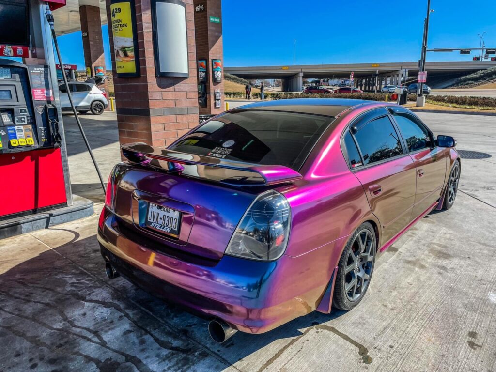
Owner: Charis Cacal

Year: 2005
Model: Altima
Color: Charcoal
Transmission: 6-Speed Manual
Trim: SE-R

Mod List:

  • 2005 Altima SE-R 6MT
  • 2014 Maxima Motor
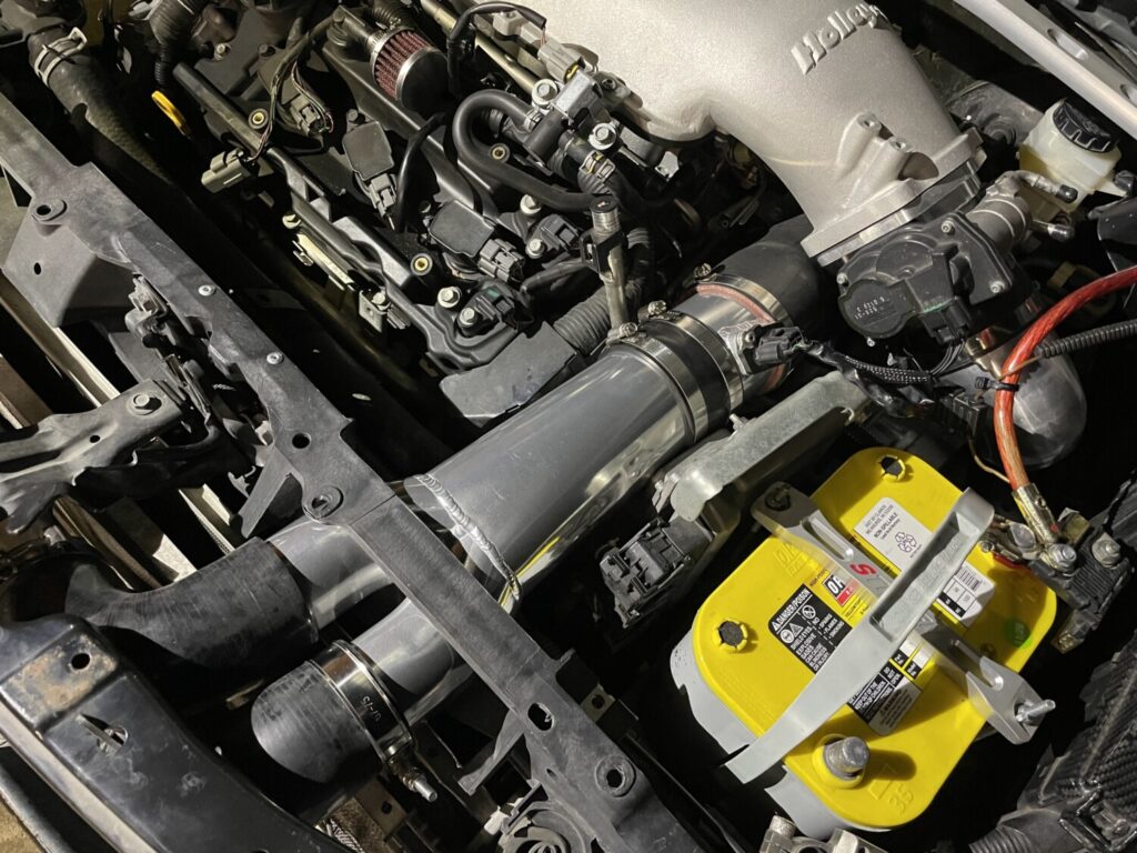
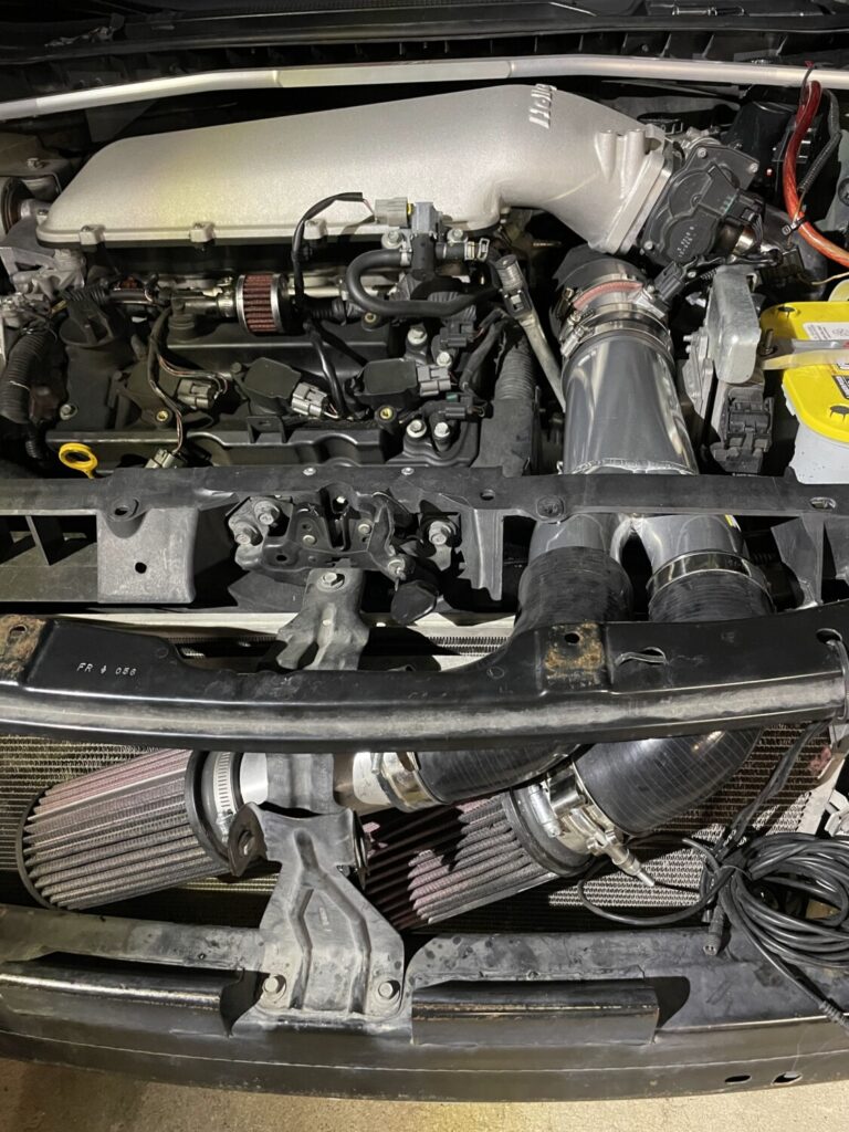
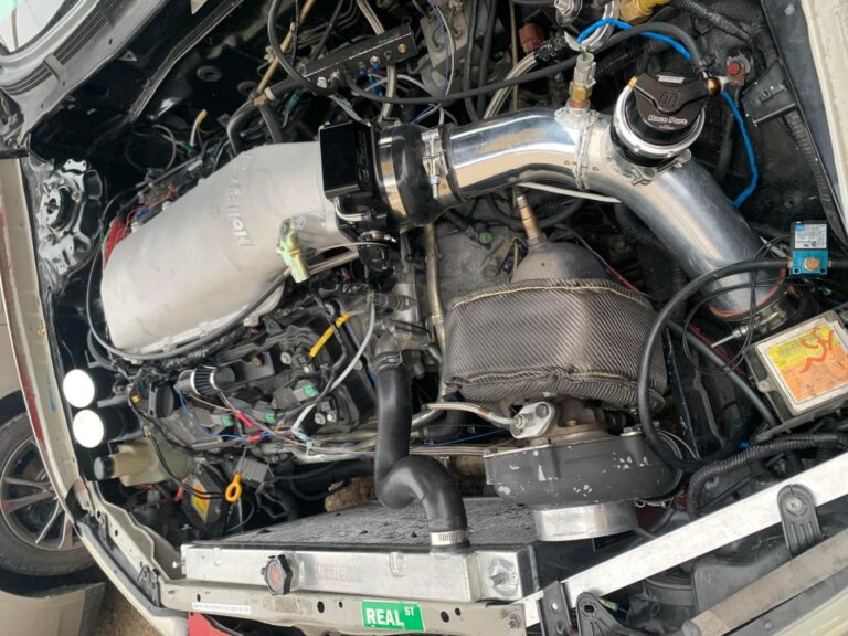
  • 105mm Holley Plenum Top
  • 102mm LS Throttle Body
  • 4″ Intake
  • Genuine Nissan GT-R Injectors
  • AEM 50-1200 E85 In-Tank Fuel Pump
  • SR*S headers (No Cats), 3″ Exhaust w/ 3″ Resonators, and Dual Borla Mufflers
  • NGK 93026 DILKAR8A8 Laser Iridium Spark Plugs—Heat Range: 8


Loading

 Community Member Credit: tatanko

 (vs. USDM 4th Gen)

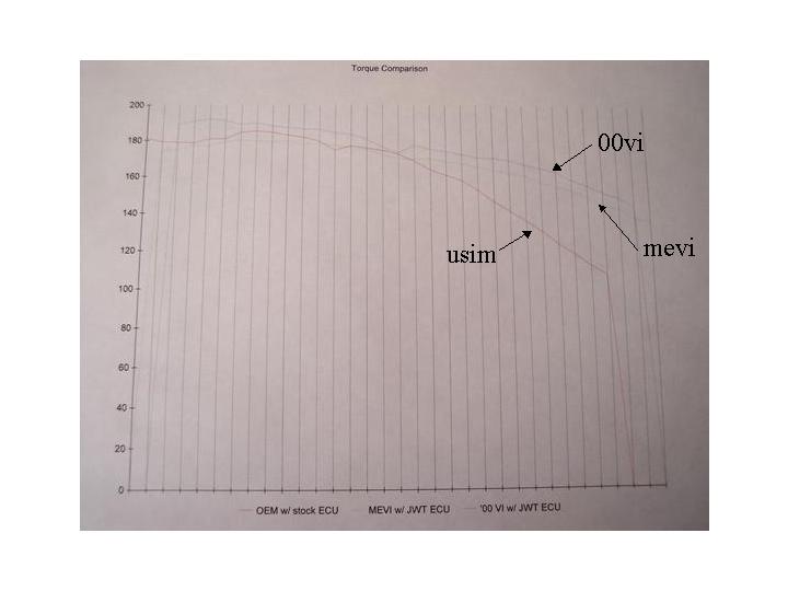
 Although not many have completed this swap thus far, it has proven itself to be a far more potent solution than the MEVI. The MEVI, however, has it’s own advantages.

Advantages

00VI…

  • Low RPM power. Rather than lose power at low RPM’s over the USDM manifold, the 00VI actually gains a significant bit of power.
  • Midrange and high RPM power. Although the 00VI and MEVI are both variable manifolds, the difference in operation and design simply allows the 00VI to outflow and outperform the MEVI even as RPMs climb, resulting in even higher peak numbers.
  • Ease of finding parts. Because the 00VI was used as OEM equipment on 2000 and 2001 Maximas in the US, parts are easily accessible at a Nissan dealer or in junkyards.

MEVI…

  • Ease of installation. The MEVI has many similarities to the USDM manifold in terms of design and layout, and was meant for a 4th gen engine. It is basically a bolt-on part.
  • History. Simply put, people have been using the MEVI on their cars for years and years and there is lots of experience and knowledge regarding it.
  • Parts. Almost all of the parts off of your current 4th gen can be re-used with the MEVI.

Disadvantages

00VI…

  • Installation and preparation. The 00VI is simply a much more daunting task. It requires modification to the manifold, wiring work, many custom parts, and a lot of time.
  • History. Or it’s lack thereof. The 00VI swap is still relatively new (by comparison) and very few people have done it.
  • Parts. Almost nothing from your 4th gen manifold can be re-used, and even re-using your stock 4th gen intake becomes a task that involves ordering parts.

MEVI…

  • Power. It doesn’t make as much peak power, and you actually lose low RPM power as a result of it’s design.
  • Parts. They are hard to come by, and often must be ordered expensively through a Nissan dealer and require a good wait to get, due to the manifold never appearing on US Maximas.

On the Dyno

Boosted…
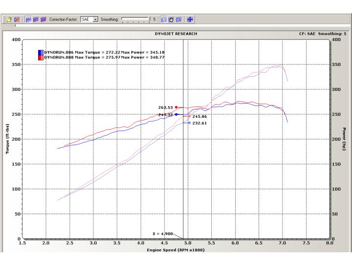
(Stephen Max’s car: 14.3 tq, 13.2 hp over MEVI and gains from 2500 rpm to 7000 rpm)
All Motor…
(BSwithTF’s car: 11.45 tq, 8.61 hp over MEVI, and gains at every rpm)

200 WHP vs. 200 WHP
(jenk01SE’s car [00VI] vs. Zack342’s car [MEVI])

Loading