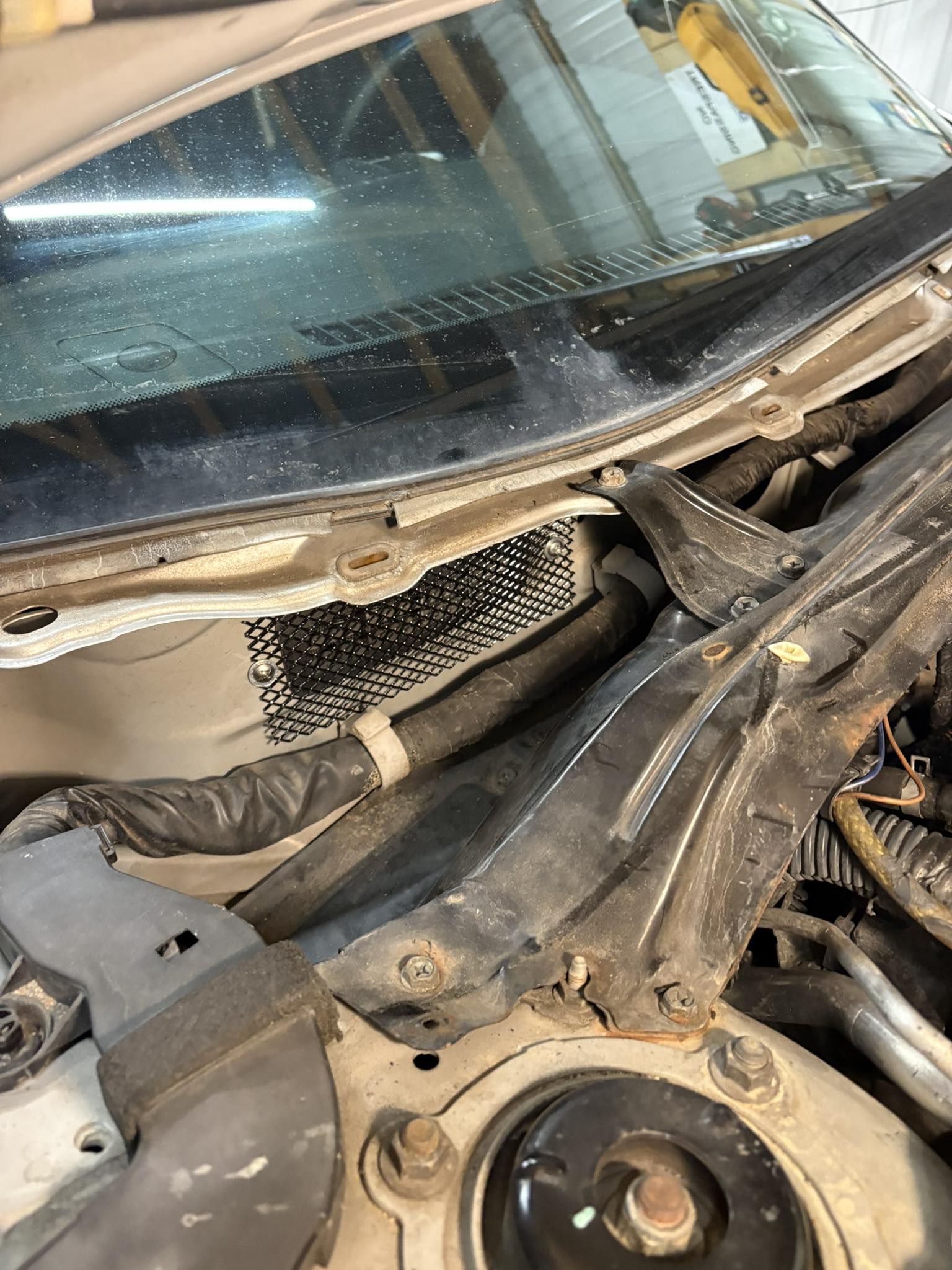
I’ve now had two separate incidents where my blower motor failed because of critters. When I opened the cabin air filter housing, I didn’t find debris—I found feathers and a full-on nest. It was so bad that my K&N reusable filter couldn’t even be saved.
If you’ve dealt with the same issue, here’s a simple and inexpensive fix: Head to your local hardware store (Lowe’s or Home Depot works great) and pick up some gutter mesh. I came across this solution on a forum, installed it, and it’s been a game changer.
Bonus: I had extra mesh left over, so now I’m adding it to my other vehicles too.
Cheap, easy, and it might save you from replacing a blower motor down the road.
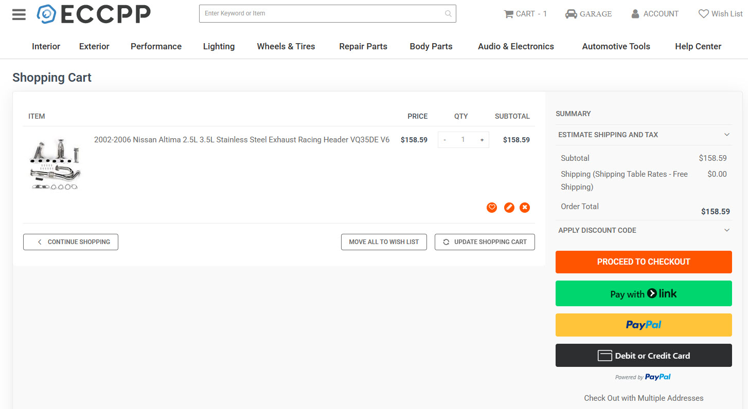
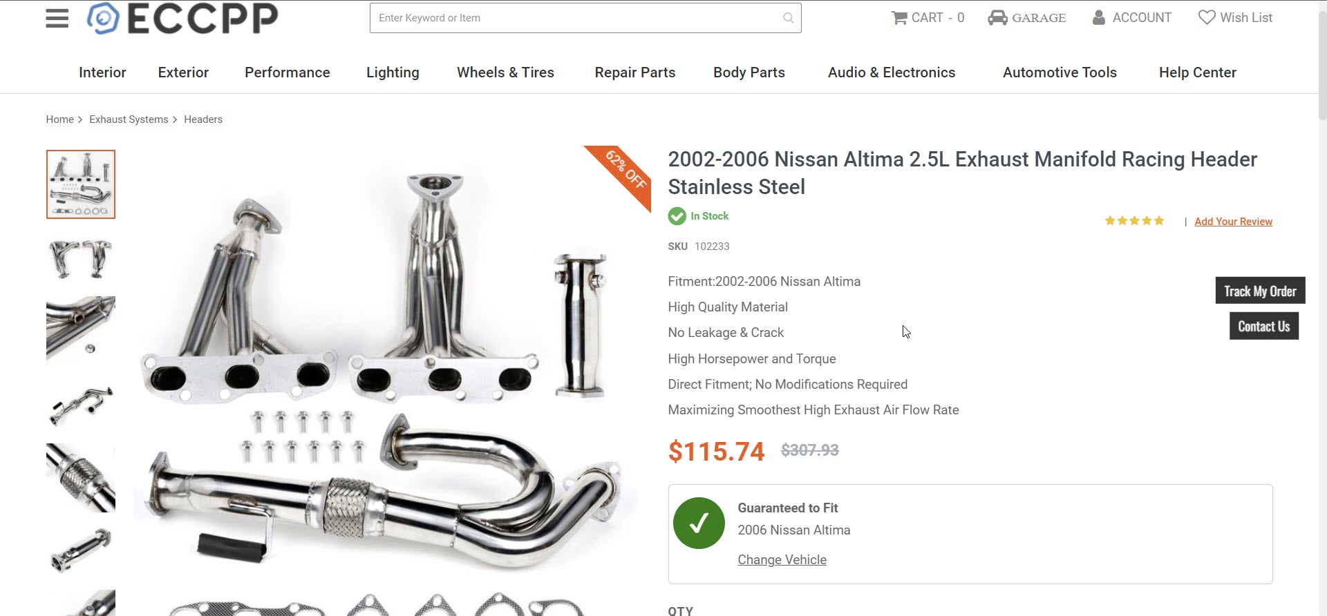
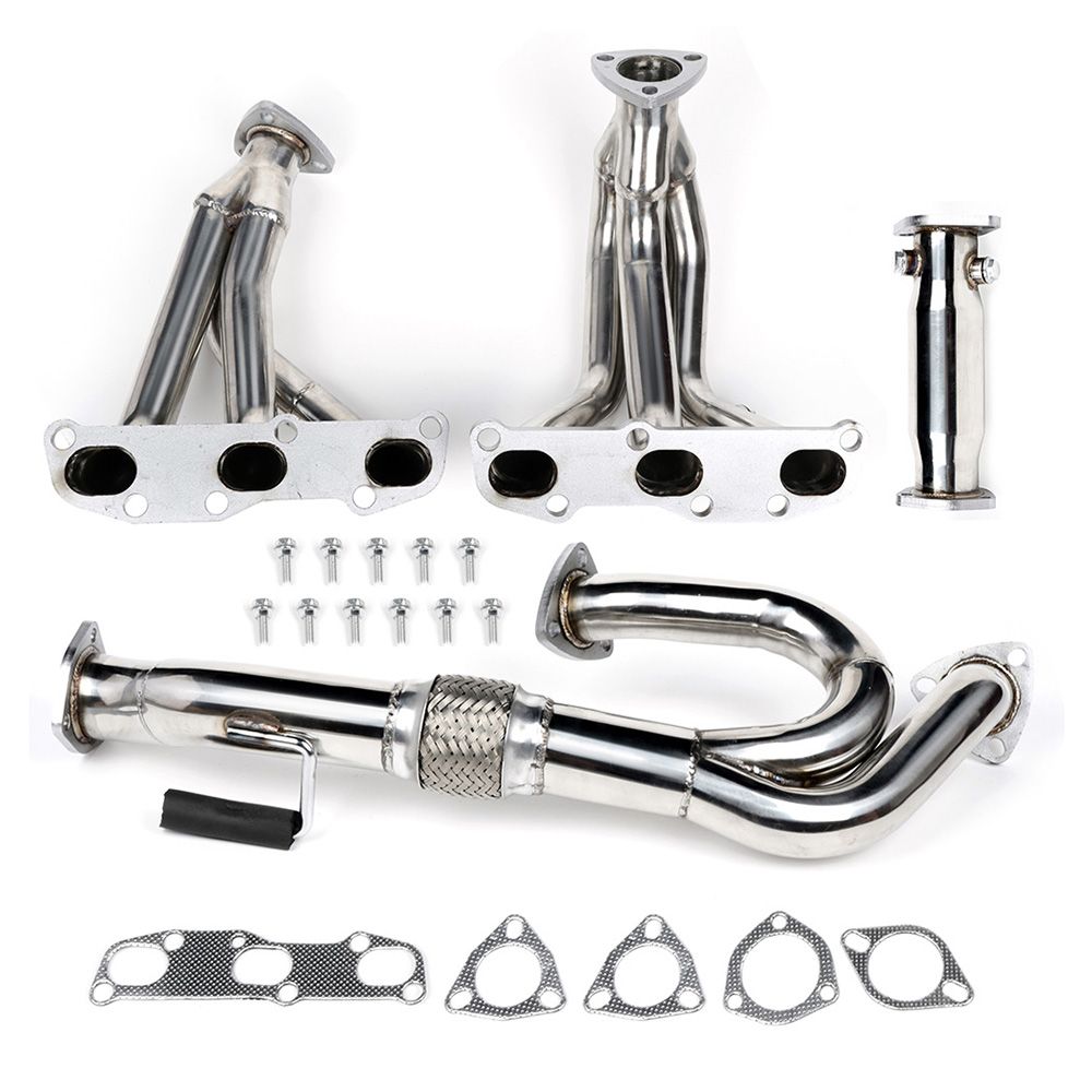
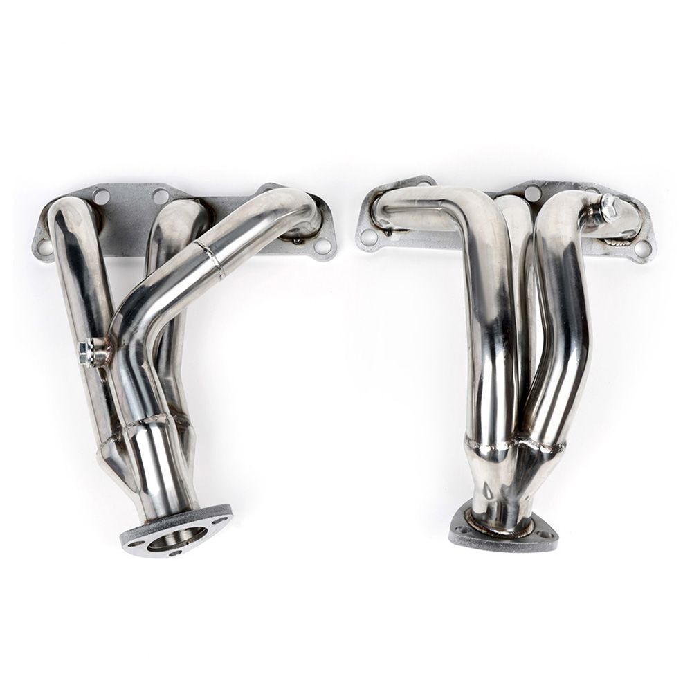
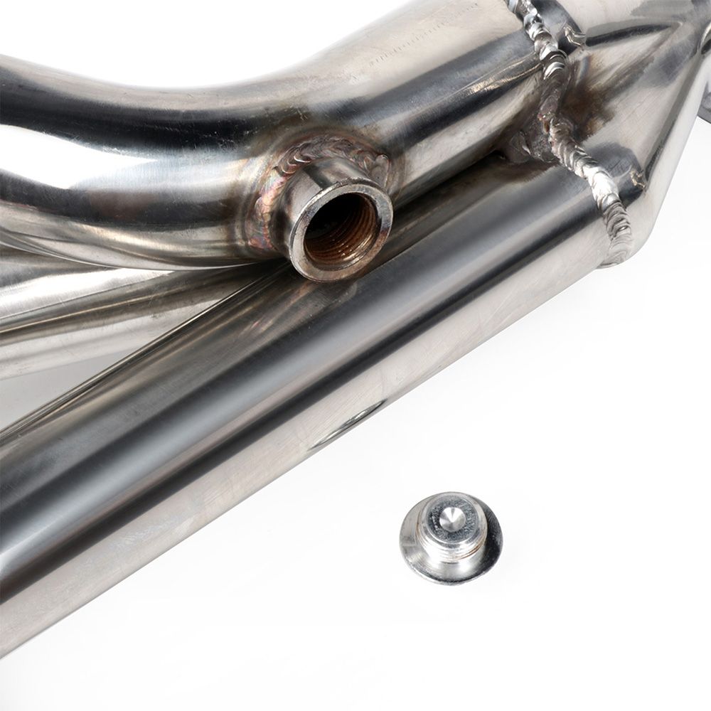
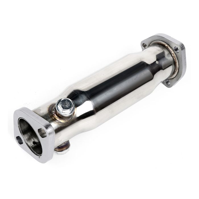
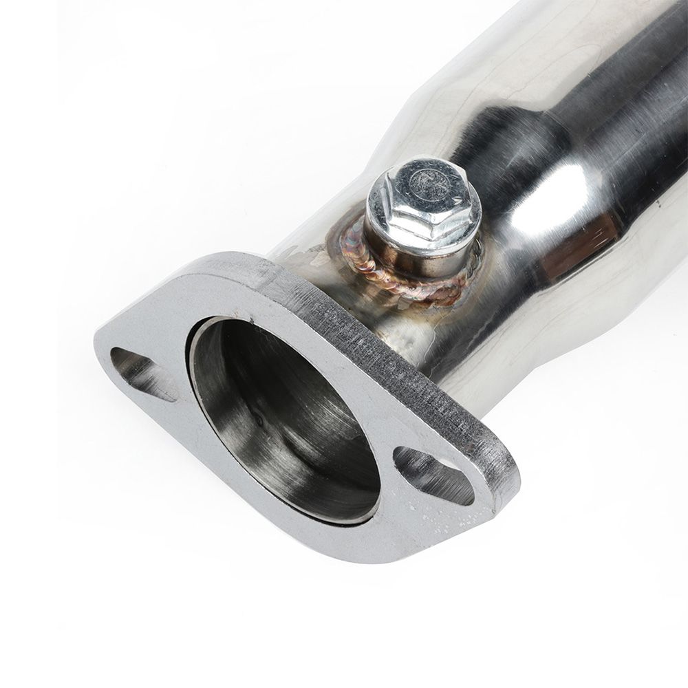
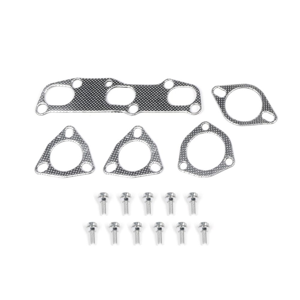
Description: 2002-2006 Nissan Altima 2.5L Exhaust Manifold Racing Header Stainless Steel Part Number: 102233 Price: $158.59 (Shipped)
Important Note:
These show 2.5L vs 3.5L. Josh confirmed they are for the 3.5L and he installed on his Maxima. He is local to them.
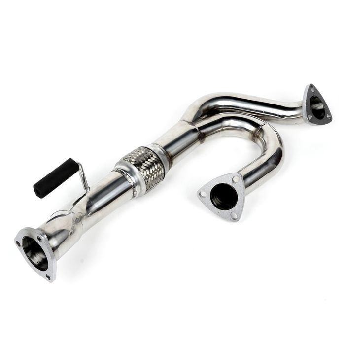
As you’re aware these require modification of y-pipe for perfect fitment. Please research it. This has always been known with the Altima VQ35DE headers. They are NOT plug-n-play. But for the price, they are very well worth it. These also come with a downpipe so it makes an even more awesome price.
A few maxima members have already ordered and confirmed this is a legit shop. They’ve received their ordered with no issues.
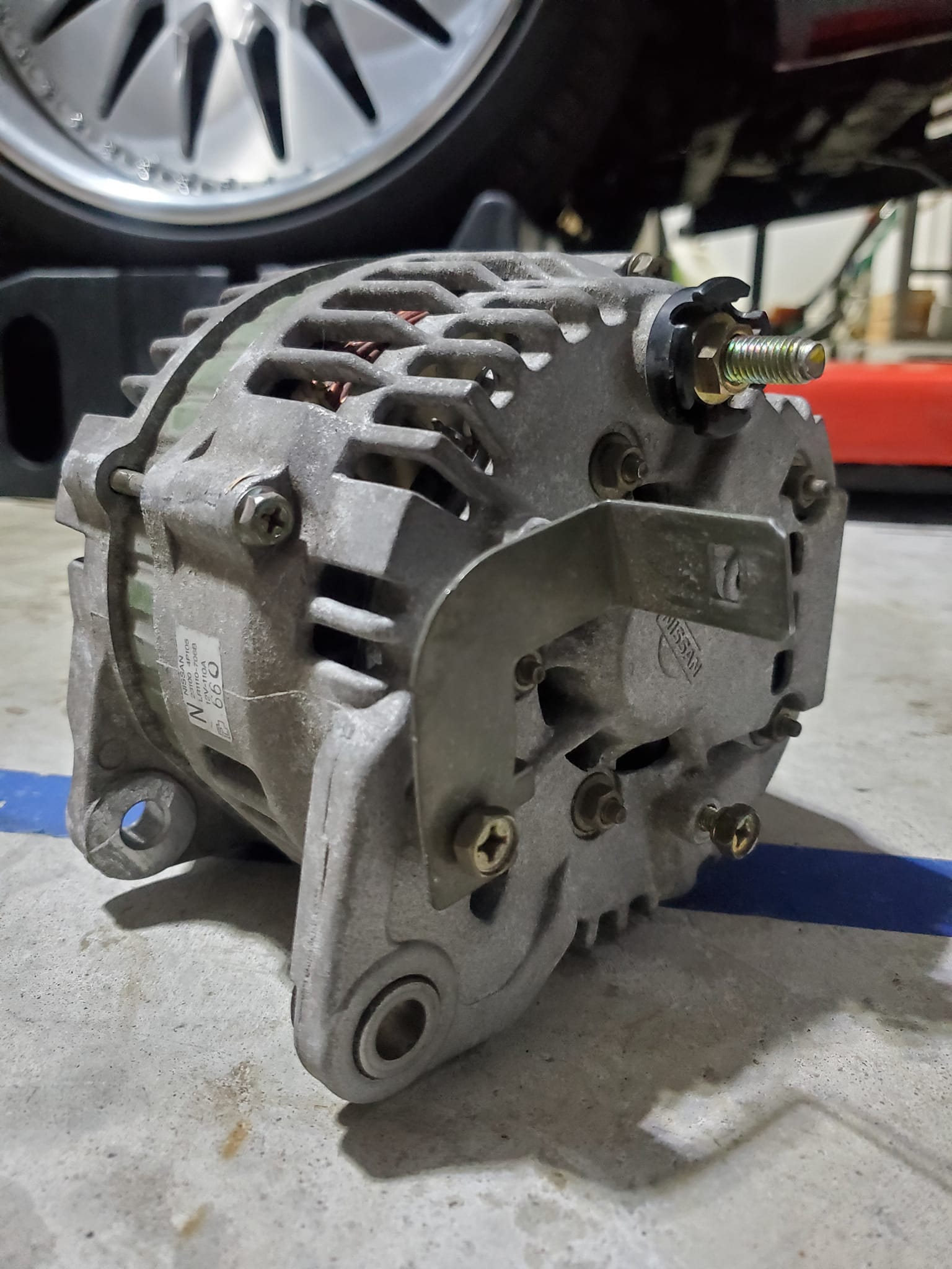
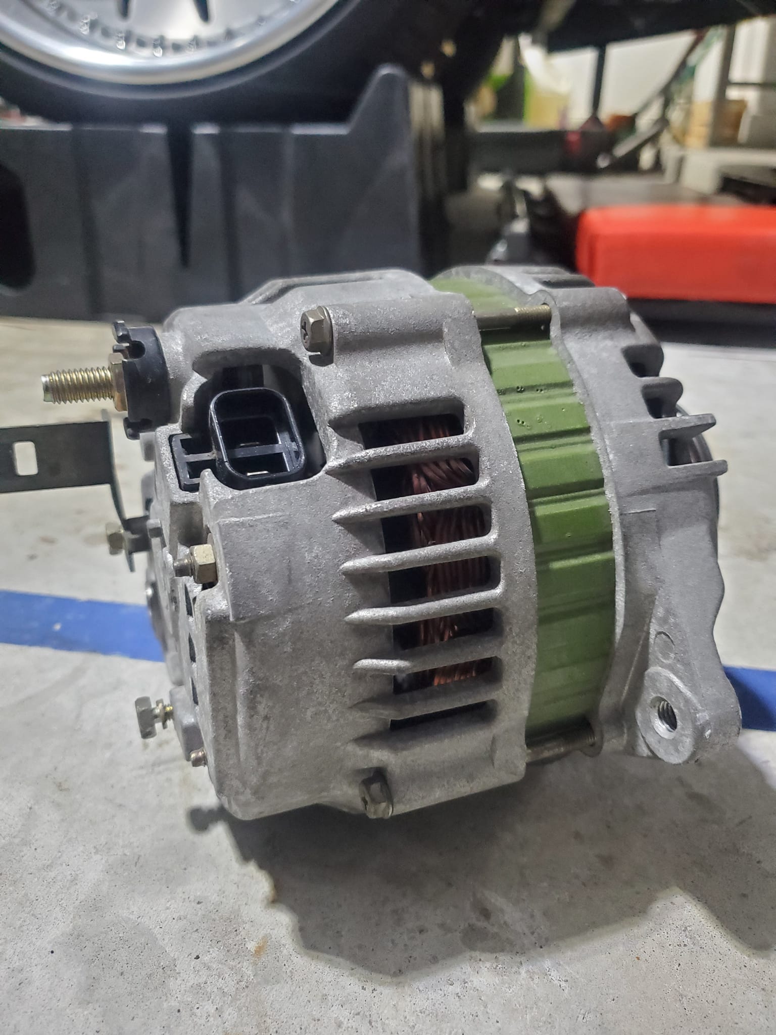
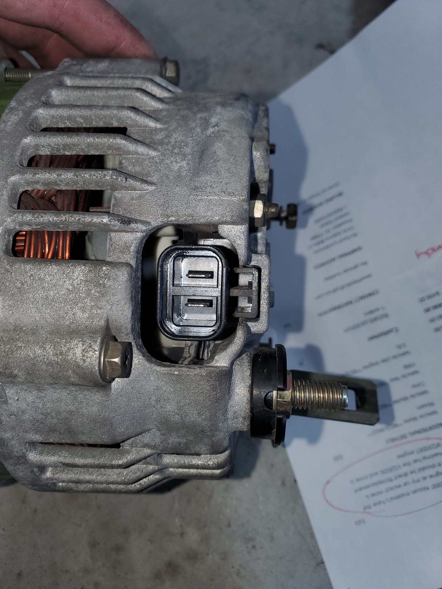
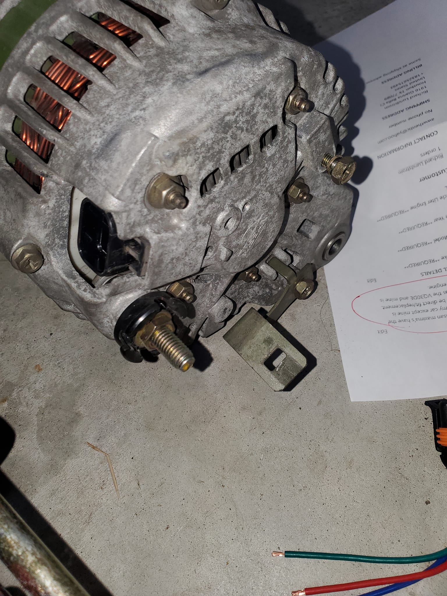
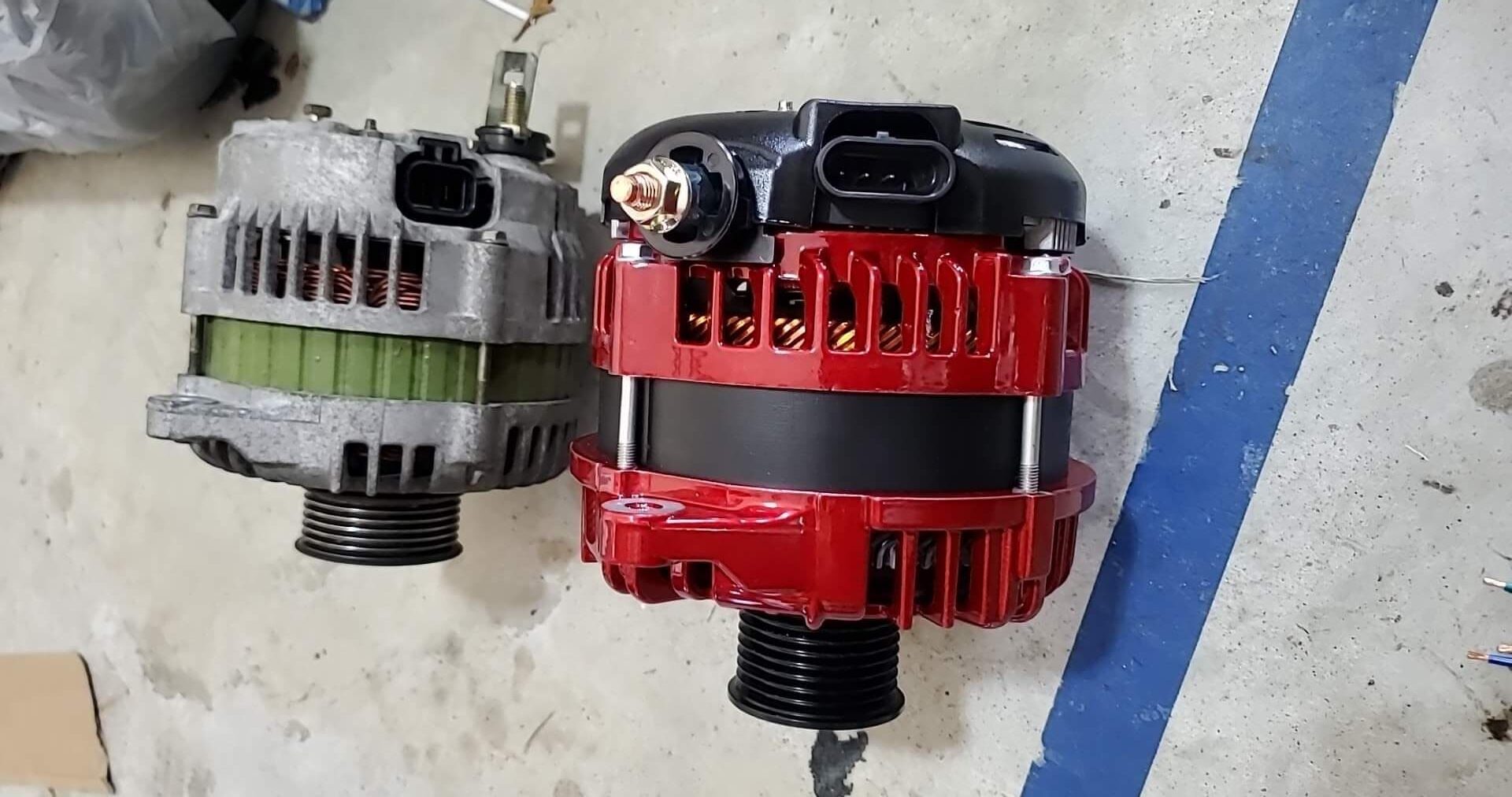
I used a high-output alternator from JS Alternators for my setup. Since I’m running a VQ30DET, I used one from a ’96 Nissan Maxima.
Important: Make sure to tell them that the power post needs to be on the backside of the alternator—not on the side. They originally sent mine with the post on the side, and I had to ship it back for modification. Once they moved it to the rear, it fit perfectly.
Also, make sure they send you the 2-pin plug connector, not the 3-pin version they initially sent me.
After spending more time with the Turbo Specialties kit, I’ve got some real-world feedback to share — both good and bad. I’m not here to sugarcoat anything; this is what you can actually expect when wrenching one of these onto your car.
The Fitment Struggles: When “Bolt-On” Isn’t Really Bolt-On
Let’s start with the bad news. While this kit looks great on paper, installation was far from smooth sailing. I ran into a laundry list of issues that turned what should’ve been a weekend project into a deep dive in creative problem-solving.
1. Manifold Misalignment
The turbo manifold wouldn’t fit over the studs — every single hole needed slight enlargement to line up properly. It’s a small tweak, but frustrating when it’s the very first step of the install.
2. Hardware Headache
The kit includes no manifold nuts. I guess they expect you to reuse the stock ones, which don’t work on about 75% of the studs. Tracking down M10 x 1.25 nuts with no flange locally was a nightmare. A small bag of proper hardware would’ve saved hours of wasted time.
3. Wastegate Bracket Clearance
The wastegate actuator bracket absolutely will not clear the motor mount bracket. I had to extend the actuator arm outward and fabricate a custom bracket just to make it work. This should not be something the end-user has to figure out.
4. The “What Were They Thinking?” Moments
Someone, somewhere, decided that red Loctite and finger-tight torque was good enough for a compressor housing bolt. Spoiler: it wasn’t. It stripped right out.
Then, to make matters worse:
The compressor housing hits the motor mount bracket.
The motor mount hits the crossmember.
The motor mount also hits an oil or coolant line — though that one was easy to fix.
And the oil return line? Yep, it interferes with the motor mount bracket too.
As if that weren’t enough, the motor mount itself doesn’t line up properly, forcing me to use spacers behind the mount bracket. That just made the compressor housing and wastegate clearance problems even worse.
Dear Turbo Specialties: Please, Do Better
To whoever at Turbo Specialties is following these threads — seriously, take this as constructive criticism from someone who wants your product to succeed.
Here’s what would make this kit great instead of just okay:
Establish proper production tolerances and actually stick to them.
Improve your quality control — small issues compound fast when everything is tight under the hood.
Buy a 4th Gen Maxima mule car. It doesn’t have to run; it just needs to exist. Use it for every single test-fit before you ship a kit. Scratched parts are better than ones that don’t fit.
Charge $500 more if you need to. Most buyers would happily pay extra for a kit that truly bolts on cleanly instead of spending days fabricating fixes.
I’m not just venting — I make money from installs like this, and even I’m frustrated. Imagine how a regular weekend warrior would feel tackling these issues in their driveway.
To Be Fair: It’s Still an Impressive Kit
Now, credit where it’s due — I don’t want this to sound like a total takedown. Despite all the fitment headaches, I’m still impressed by how complete the kit is. It includes nearly everything you need, and once everything is sorted out, the performance potential is absolutely there.
But quality control and consistency matter just as much as horsepower numbers. The foundation is solid — it just needs refinement.
Current Setup and Upgrades
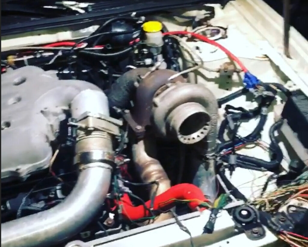
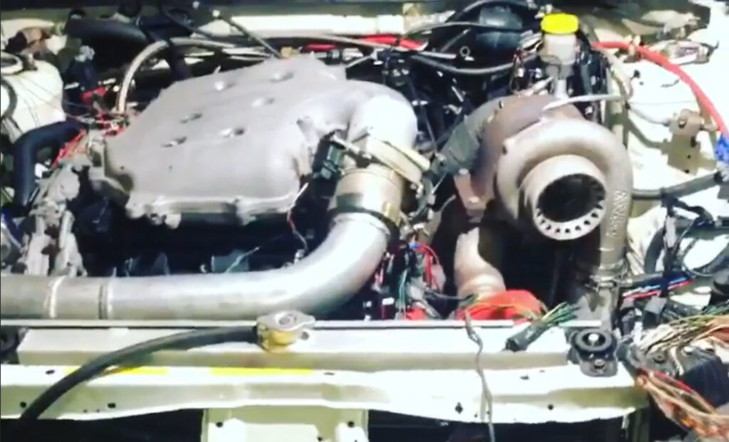
There have been quite a few changes made to the kit since my initial install. I’m now running a Garrett GT3071R with a custom 3″ downpipe — a huge improvement over the stock setup.
At the moment, I’m still tuning with an FMU, but I’ll be switching soon to GReddy E-Manage paired with 440cc injectors for finer control and reliability. The MAF sensor has also been relocated to the charged side, which has helped smooth out airflow readings under boost.
I don’t have dyno numbers just yet, but they’re coming next week. For now, the car is running 7 psi, and even with an open downpipe (which makes it insanely loud), it feels incredibly strong — easily more powerful than the previous dyno numbers posted by Doc when he installed the kit.
A big shoutout to Kevin (KRRZ350) from Goodwin Motorsports for handling the installation. He worked through every issue that came up, and the fabrication on the downpipe is absolutely top-notch. One note: if you go with a 3-inch downpipe, you’ll have to sacrifice your A/C system — there’s just no room to keep it.
Final Thoughts
The Turbo Specialties VQ30 Turbo Kit is a bold product for an under-supported platform. It delivers great results once it’s working, but getting there takes patience, fabrication skills, and a willingness to improvise.
If Turbo Specialties tightens up their manufacturing and test-fitting process, this could easily be the go-to kit for Maxima enthusiasts. Until then, consider it a solid project — not a plug-and-play solution.
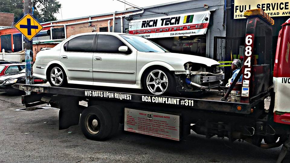
Turbocharging the VQ30: My Experience with the Turbo Specialties Kit on a 2000 Nissan Maxima
As many of you already know, I recently installed the Turbo Specialties VQ30 Turbo Kit on my 2000 Nissan Maxima. Since quality turbo kits for the Max are few and far between, I wanted to share my honest experience — from unboxing to tuning — for anyone considering taking the plunge.
First Impressions: A Surprisingly Complete Kit
Right out of the box, I was impressed. This is easily one of the most comprehensive kits I’ve seen for the Maxima platform. It includes:
A standalone control unit that combines multiple functions — turbo timer, boost controller, boost data logger, and injector driver.
A set of injectors included in the kit, meaning no need to source your own or risk running lean.
New motor mount, engine bracket, bolts, turbo manifold, and downpipe — all included.
The control unit deserves special praise. It’s well thought out, easy to wire, and performs exactly as advertised — turbo timer and all. Having everything integrated in one module saves a ton of time and money versus piecing together electronics separately.
Installation Notes: The Good, the Tricky, and the Workarounds
Oil Return Line
The only part I outsourced was dropping the oil pan for the return fitting — that cost me about $450. The kit’s return line is a fiber-wrapped 5/8″ rubber hose, but I recommend upgrading to steel braided 5/8″ line for durability. Pick one up from Pep Boys for around $30, along with a 5/8″ L-fitting and collars to protect it from road debris.
Heat Shield
The included heat shield requires trimming to fit. A rotary grinder or Dremel makes this job much easier. Mark your cut lines first, trim carefully, and smooth the edges — sharp metal near a turbo is never a good idea.
Turbo Fitment
The top oil inlet tube needed a slight bend to clear the cooling fan. I used a $6 aluminum tube bender from AutoZone and a Dremel to shave the fitting edge — just enough to clear, not weaken it. I also had to rotate the compressor housing (“snail shell”) to align it properly with the intake. After several radiator test fits, I locked everything down tight. Be careful with the oil return fitting; if it’s not seated correctly, you’ll have oil everywhere — ask me how I know.
Manifold and Wastegate
Mounting the manifold is a two-person job. Follow the FSM torque pattern, and finger-tighten the bottom center nut first before working outward. The wastegate bracket needs minor trimming to allow the O₂ sensor to thread in properly — mark carefully, trim sparingly, and test-fit multiple times.
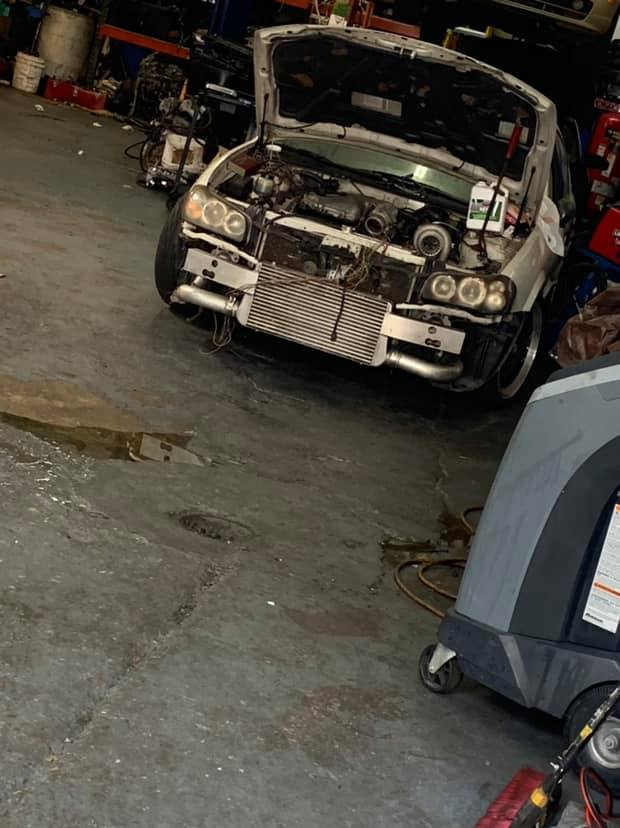
Charge Piping and Intercooler
Once you reach this stage, you’re almost done. You’ll need to cut holes in the plastic underpan to route the charge pipes. On my setup, the driver’s side pipe (#7) hung too low, so I shortened it about 1.5 inches to sit flush with the fascia. I mounted the intercooler brackets to the lower frame using self-tapping screws. Tip: mock up all the piping before bolting in the intercooler to ensure perfect alignment.
Wiring
Follow the provided diagrams carefully. The wiring is straightforward, with the only tricky part being the tachometer wire tap at the ECU. If you don’t have a factory service manual (FSM), you can find it at PhatG20.com — trust me, it’s a lifesaver.
Startup, Tweaks, and Break-In
Once everything was buttoned up, I double-checked every connection, started the car, and checked for leaks around the manifold and fuel lines. A few bolts needed retightening, but otherwise, the system came alive beautifully.
I drove gently for a week to let the ECU adapt, and sure enough, it adjusted timing automatically. The blow-off valve sounds fantastic — smooth and sequential in tone — and the turbo spool is addictive. It completely transforms the character of the car.
Dyno Results and Performance
Under test conditions:
Humidity: 94%
Dew Point: 60°F
Barometric Pressure: 30.5 inHg
Temperature: 62°F
Time: 1:15 PM
At 7–8 psi, the results speak for themselves:
Metric
Stock
Turbo Kit
Wheel Torque (wtq)
~173
244.3 @ 4650 rpm
Wheel Horsepower (whp)
~186
220.3 @ 5100 rpm
That’s a solid gain for a bolt-on kit running modest boost through an automatic transmission with a T28 ball-bearing turbo. If you want to push it further, you can easily upgrade to a larger turbo down the line.
Final Thoughts
At $2,888 shipped from California to New Jersey (arrived in 5 days), this kit is an outstanding value. The instructions are thorough, the hardware fits well, and the performance is night-and-day compared to stock.
If I had to do it all over again, I wouldn’t change a thing. The install was challenging in spots but deeply rewarding — and the end result feels OEM+ in both reliability and response.
If you’re considering this setup and need help during your install, feel free to reach out. I’ll be happy to walk you through any tricky steps.
The Turbo Specialties VQ30 Turbo Kit truly brings new life to the Maxima platform — and in my opinion, it’s worth every penny.
The Radium Engineering VQ35DE top-feed fuel rail setup fits perfectly under the stock VQ30DET intake manifold when using 33mm top-feed injectors of your choice.
You can route the fuel lines either direction — out the front (like factory) or out the back. I’m going with -8 lines for feed and return and a -10 crossover at the rear.
The only modification needed is to trim a small bump-out section on the lower intake manifold (pictured).
I’ve already done a test fit, and everything lines up nicely.
CV axle had a torn boot, so I decided to try out a universal replacement instead of pulling the whole axle. The quality was actually surprisingly good — durable material and a solid fit.
After gluing the two halves together, I gave it a few hard pulls to test it and it didn’t budge. While I was at it, I also cleaned and coated the other boots with some goop to help prevent future tears.
I’ve gone this route before and never had any issues, so we’ll see how this one holds up — but so far, I’m impressed.


")


 — Upgraded with High-Output Alternator")


")


 Installed on Altima SE-R")