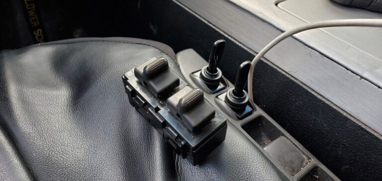
My recline and power seat move button stopped working. Seems like they were stuck. I’m sure I could have taken it off and tried to prepare it but I found a better solution that worked for me. I bought two Dorman 85919 toggle switches and swapped the button with that. The switches fit great and work 100%. A good option for those who don’t want to pay $100 bucks for a new one. This costs less than $10 bucks to do.
So I was having some cold start problem. I knew that my battery was good so I did some research and it seemed like the AC Amplifier was the best culprit. So here is the process of replacing the AC Amplifier.
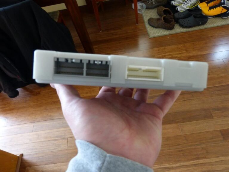
First off, the AC Amplifier is the most expensive plastic box that I’ve ever bought and this is what it looks like.
The only explanation I could find was that the AC amp gathers climate information( outside temp, humidity, etc), sends it to the ECU and that determines the fuel/air mix on start up.
2003-2005 FX35 / FX45
Part Number: 27760-CG000, 27760-CG700, 27760-CL000, 27760-CL01A Part Description: AMPLIFIER – CONTROL, AIR CONDITIONER Price: $650.97
2006-2008 FX35 / FX45
Part Number: 27760-8Y71A Part Description: AMPLIFIER – CONTROL, AIR CONDITIONER Price: $650.97
There are three cable connections at the back of the unit.
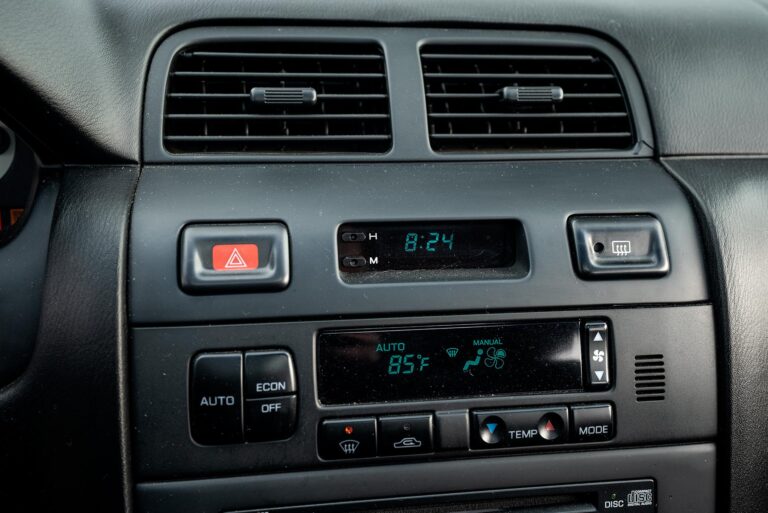
The AC Amplifier sits immediately behind the AC Controls under the main display stack in the middle of the dashboard.
To replace your AC Amplifier, do the following:
1. Take a plastic pry tool or something non-scratching and slowly pry around the bezel of the center display panel.
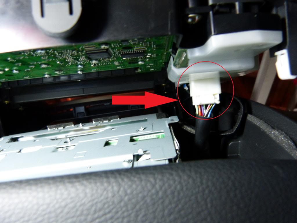
2. You’ll need to slowly make your way around the entire bezel until it starts to pry up, before you pull the center stack out, there are two cables that need to be disconnected. One white connector, seen here from the bottom.
…and one black ribbon cable seen here from the passengers side.
Once these cables are disconnected, you can remove the entire center stack and set aside for the time being.
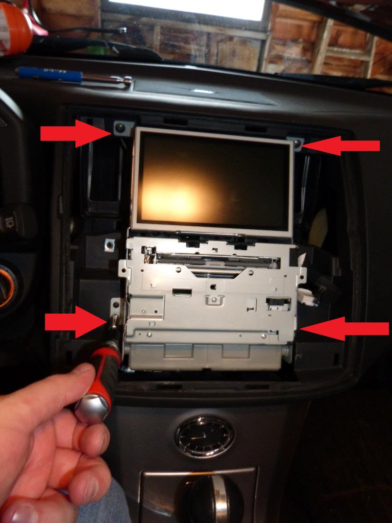
3. You will now see the guts of your center stack, and the AC Amplifier, the gray plastic box at the bottom. You will need a Philips head screwdriver to remove the 4 screws holding the center stack in place.
4. Now you can pull the entire center stack slightly out of place so you can access the 2 Philips head screws that hold the AC Amplifier in place. There is one on either side of the unit, remove them both.
5. Once these two screws are out, you should be able to pop the box out of place and more easily access the 3 cables at the rear of the AC Amplifier.
6. Remove the three connectors, replace with the new AC Amplifier and reconnect the 3 cable assemblies.
7. Put the AC Amplifier back into place and return the screw on either side of the unit.
8. Slide the Center Stack back into place and return the 4 mounting screws back into place.
9. Before returning the faceplate, re-attach the white cable and the black ribbon cable.
10. Place the bezel back into place and slowly push firmly around the entire outside of the bezel, you’ll feel the face click back into place.
11. Start up your car and go through all of the functions on the center stack to ensure that everything still works.
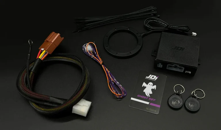
Hi guys! Jordan Distributors recently made a full plug and play kit for our cars so I figured I would do a write-up on how to install it. Here’s everything the kit comes with (the button you choose may vary)
WARNING: If mounted in factory key location, you WILL lose your steering wheel lock feature. If you have an automatic, you WILL lose your shifter lock as well. For 99+ models, you will need to bypass your immobilizer. The install guide that comes with the kit will tell you what wires to use. For 95-98, you can just ziptie them out of the way.
1. First thing you will want to do is disconnect the negative terminal on your battery.
2. Remove all trim surrounding the steering wheel and the ignition cylinder, as well as the panel covering all the wiring underneath.
3. Disconnect your ignition cylinder, and remove everything. There are two tamper proof screws holding it on, as well as the steering wheel lock mechanism. You can either Dremel some flathead indents into them, or use a screwdriver and a hammer and chisel them around so they unscrew. They are not tight.
4. Unplug your brake connector switch above the brake pedal. This kit comes with a clip connector that you will clip onto the red and green wire. Clip that on, then plug the orange wire into the clip.
5. Install the JDi main harness from the control box to the male connector where your original ignition cylinder plugged into. Ground the black wire from the harness somewhere.
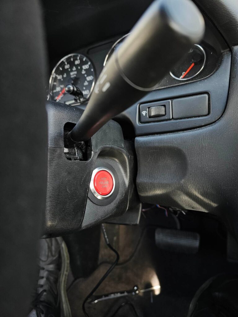
6. Put your new start button into the original key cylinder location.
7. You’re nearly there! Plug everything into the JDi control box, and tuck everything into a place that it won’t move. The key sensor can also be mounted anywhere, but I’d recommend taping it with some 3M tape behind the bottom trim panel.
8. Reconnect your negative battery terminal, go over all of your connections to make sure everything is where it’s supposed to be, scan your JDi keyfob or keycard over the sensor, put your foot on the brake, hit the start button, and you are done! Just be sure to put all of your trim pieces back together as well.
NOTE: The car will not turn off if you hit the button while driving. You must push your brake pedal in when pushing the button to turn your car off.
Jordan Distributors inc. Ghost Key – Plug and Play Push to Start Conversion Kit comes with everything that you will need to add Push to Start to your vehicle without any guesswork, cutting or splicing needed!
Start Button – Either Red or Silver (both have red backlit letters)
Start Button Adapter for Factory Key Hole
2 Standard Black Key Fobs
1 Ghost Key card
Sold Separately:
Additional keys (Leather Fob, Adhesive back disc, Additional cards)
Hole saw (only needed if you will be mounting your button somewhere other than the factory key hole)
Kill Switch (prevents the vehicle from starting even if someone steals your unique key)
New Features Included with Ghost Key:
Black key fobs included standard
White LED Button Included Standard
Ability to Long Crank From the Second Key Position
Upgraded Relays, Chips and Components
4 DIP switches for custom settings
1. Adjustable engine cranking time
2. Adjustable Auto Re-Locking Time
3. Ability to Auto Fuel Prime Before Starting (if needed)
Add some much needed security to your vehicle! Make it harder for thieves to steal your pride and joy while adding the style and functionality of a modern vehicle!
Using The Ghost Key – Push to Start Kit:
1 press is like turning the key 1 click
2nd press is like turning the key 2 clicks
3rd press turns everything back off
Or press the brake pedal and press the button and the engine will start
Easy Install
Plug and Play
No programming, even if the car battery dies
No cutting
No splicing
Even works with performance engines that take longer to start! (Just hold the button until the engine starts)
This kit is completely plug and play and will come with everything you will need to install it in your vehicle.
**If you do not see your vehicle listed we may have one available soon as we do have other applications currently in development.**
No cutting or modification is necessary.
Install time is approximately 30 minutes – 1 hour.
For a complete install guide, please refer to our install video under the Install Guide tab here on our website.
Shipping: Shipping in the Continental 48 US States is included free of charge. If you are located outside of the Continental US you can simply add your desired products to your cart and, after entering your address, the website will calculate the exact shipping cost for you.
All of our kits include a 12 Month Warranty against any manufacturing defects. Legal Disclaimer: By purchasing this product, the customer takes full responsibility for any use, and/or misuse of the product and agrees that Jordan Distributors inc. holds no responsibility for any consequences, legal, or other, of such use and/or misuse. Off-road use only. Any cutting or modification of any of our products will void all warranty.
**DO NOT clean your start button with harsh chemicals. This can damage the finish on your button. We recommend using a mild detergent on a damp cloth. Our warranty will not cover damaged start buttons due to misuse. As long as harsh chemicals and sharp objects such as car keys are kept away from the button, the finish will remain nice for years to come. All of our buttons have been proven reliable to over 400,000 presses**
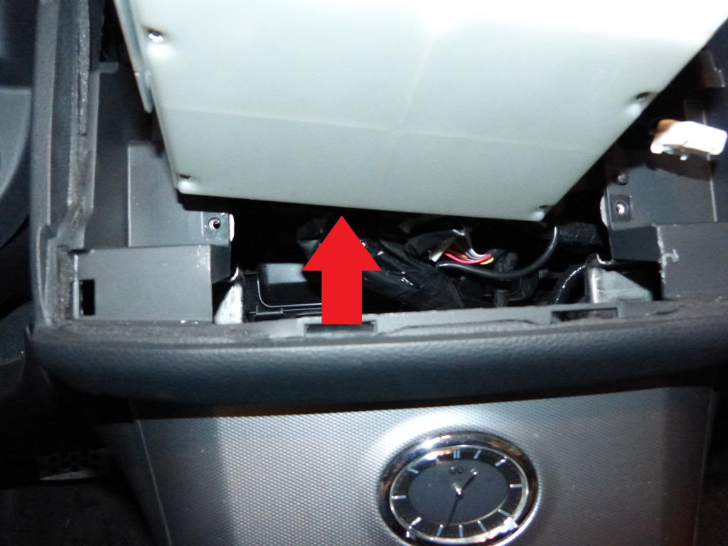
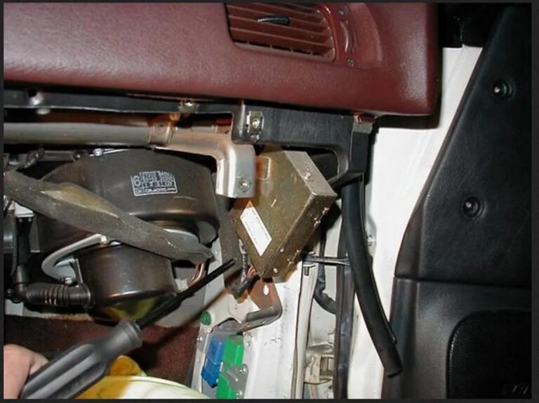
Okay I am Seeing a lot of problems how to reset the keypad, Well my part of the write up is to help those with some pics of the location of the security unit. Get a flash light and move the passenger seat all the way back. and lay on your back facing up, head under the glove box where the passengers feet would be. now look up to your left… facing the door you will see a brass box with wires coming out of it.. locate the number starting with the letter “S” ex. S1329123..write those numbers down. IT SHOULD BE 7 DIGITS LONG!
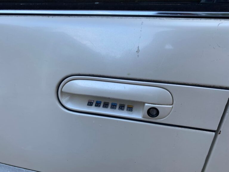
Get out the max and and lock the doors. The Security light should come on the dash and then turn off. Press the St Button (last button to the left) Enter the digits you got from the box, after you enter it you hear beeping from the horn, at this time you must enter a new code with in 10 seconds. Pick a number that you can remember easily. The Code cannot be repeating
Below is an example:
Code consists in this pattern:
Keypad Button 1= 12
Keypad Button 2= 34
Keypad Button 3= 56
Keypad Button 4= 78
Keypad Button 5= 90
Pattern Notes:
Any combo of the keypad buttons 1,2,3,4,5
Cannot be repeated… 1 1 5 4 3
Good code is……… 1 4 2 4 1 numbers dont repeat back to back
like the first one.
I think the code can be anywhere from 3-8 numbers.
I used this photo since my image station account no longer exists I Googled and found this pic from here on the org.
I had my Maxima since Sep 01.. and i was wondering the same thing on how to change my code… The dealership (stealership) wanted to charge me 100+ to take out the glove box and “Reprogram” the computer. B/S, and all it took me was 3 minutes…when you put your pass code you can open the window, open the trunk and or course open the doors.. the only thing you can close is the door.. the windows and the truck have to closed manually.
To find the code, grab a flashlight, then look behind the glovebox, toward the right side tire.. you’ll see a gold colored box with a sticker on it. It has three numbers on it. the middle set (IIRC) is the correct number. it should be around 7 digits.
Now go back outside the car to the keypad. Hit the clear button, then punch that number into your keypad, then you’ll hear a long, sustained beep. While it’s sounding the beep, enter your NEW key code into it. It has to be at least 3 or 4 numbers, forget the total. When you’re done punching it in, just stop pushing buttons and let it sit for a few seconds.
When it gets done beeping, hit the clear button again and punch in the code you entered. It should unlock the doors if they’re locked. Hit the button with TRK on it and it’ll pop the trunk. Hit the WDW or whatever button and it will roll down the front windows.
The information display on my 2014 recently stopped working I suspected a bad connection. I removed the gauge cluster and found the ribbon connector, located at the rear of the cluster, This ribbon connects the small LCD display to the cluster.
Because it is pretty cheap and flimsy this connector can come loose and cause the display to not work at all or not work properly. I just removed the plastic connector and reseated it and the ribbon cable. The display now works fine. I’m willing to bet this is the cause of the majority of the problems with this display. Removing the cluster is a surprisingly easy job. I think most people could do this repair in 30-60 minutes.
I would not be surprised if other Nissan vehicles such as the Altima have the same issue. The instructions, although relatively simple, make it look more complicated then it really is. If you work slowly and carefully there really is not much you can screw up. I think I had to remove a total of 5 or 6 screws to get the display out You may have to remove a couple of connectors.
Instructions (Credit: walters_12)
Well, we finally got some near-freezing temps on a sunny day that allowed me to be outside for a while. Nopike was correct on two fronts: the fix worked and the entire job took about 30 minutes. So, an absolutely huge thanks; you saved me at least $1,000! I should mention that, much to my disappointment, this fix did not work immediately; however, my Information Display came back online after about 30 minutes of driving. It could have something to do with how I placed the Information Display’s ribbon cable (see below). Admittedly, I was a bit nervous before starting, but I think most anyone can tackle this job. As a reference, I’m handy, but have no experience with anything auto-related. Pictures are posted in the next post (the first and last pictures were taken just over a month apart). Below is a description of the steps I followed to complete the job.
Documents
1) I downloaded the 2012 version of section IP-Instrument Panel and printed pages IP-10, IP-11, and IP-16.
*Note parentheses indicate the part number on page IP-10, whereas the brackets indicate the document page numbers.
Move the steering wheel to middle-lower position. I didn’t, but it would have made getting at the Combination Meter screws easier.
Disconnect the battery
Remove the Instrument Side Finisher (5) [IP-16]. It pops off with standard screwdriver and gentle pressure.
Remove the Fuse Block Cover (8) [IP-16]. It just pulls off.
Remove the Instrument Lower Panel (7) [IP-16]. There is one screw you’ll see after removing Fuse Block Cover. There are also three metal clips near top (two left; one right) that pop off with a gentle pull. I let the Instrument Lower Panel hang gently, but you could (optionally) completely remove the Instrument Lower Panel by disconnecting the harness connectors and aspirator hose.
Remove Cluster Lid A (22) [IP-16]. There are two screws near the bottom and four metal clips evenly spaced at top that pop off with a gentle pull. I just let it hang over the center console.
Place a towel or t-shirt on top of the steering column to prevent scratches and remove the Combination Meter (15) [MWI-122]. There are three screws (bottom left, bottom right, top middle). I completely removed the Combination Meter by disconnecting both wire harnesses. I did the rest of the job inside the house.
On the back of the Combination Meter, identify gold ribbon cable for Information Center (bottom, middle). Using a needle-nose pliers, I removed the long, tan plastic piece holding ribbon cable. I then placed the ribbon cable back into position (there will be leeway left and right) and reinstalled the long, tan plastic piece that holds the ribbon cable.
Reassemble by following steps 1-7 in backwards order.