The next two pics are meant to show how much more of a straight thru shot that the flow path is in the 350Z LIM.
The first one is the FWD Maxima LIM
Notice how the 350Z path below is much straighter.
Notice on the 350Z port below there is a small machined step on the inboard lip. It only goes about halfway around the port circumference. It is on the wrong side of the port to prevent flow separation so there must be another reason.
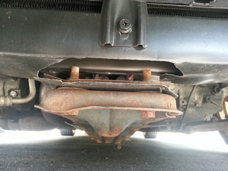
So upon installation of the kit, my car developed a small oil leak that turned worse as time passed. It started after installing the supercharger, so I tried everything possible. I replaced sandwich plate & fittings, feed line fitting and eventually after pulling the blower, I saw that it was not coming from the drain back tube or seal on the drain back nipple. The drain back tube was not kinked either.
So this is about 2 months of driving with the leaking seal…
The cleanup process was possibly the most tedious task of this whole process
First step is to take the blower off the plate, then remove the pulley. Here is the blower with the pulley off, as you can see there is a whole lot of oil around the input shaft.
In order to take the front cover off, you need a standard allen set (I can’t remember the exact size, but I got a variety pack at Lowe’s for $20 that you’ll need anyways to take the blower off the plate).
Remove the 10 allen bolts. Next, use a small flat head screwdriver to pry the front cover off the two pegs that keep the cover aligned.
Front Cover:
Supercharger internals:
Note: You can see the two “pegs” in the last picture that are at the two oval ends. The input shaft/gear is on the right and the impeller gear is on the left. There are 2 sets of bearings, one for each shaft.
You can see in this picture how destroyed the seal actually is…
Next, take a large socket (I used a 27mm) and press out the old seal and tap the new one in. Here’s the remains of my old seal…
And here is the front cover with the new seal installed and all cleaned up
Back side:
S/C internals with the old seal removed and double checked to see there was no remains in the input shaft bearings. Also make sure you clean up the entire front surface where the front o-ring seal is seated.
Finally, you need to replace the large front cover o-ring seal, as they are a one time use seal. Also make sure that both metal gaskets that go over the bearings are in their original place, the flat one directly on the bearings, and the wavy one on the outermost part of the cover.
Finish by tapping the front cover on softly with your hands or with a rubber mallet, making sure that the o-ring stays placed (sorta a pita, it took a couple tries but finally got it).
Finally put the 10 allen bolts back on to seal the front cover to the blower. I torqued them relatively tight (hand tightened) and did not use any thread locker/sealant, as there was none previously on the threads.
Put the pulley back on, and throw the plate back together and you’re good to re-install on the car.
Here is the link for the website that I bought the seals. You need:
So when all said and done, I spent $45 dollars and about an hour of my time that would have cost me $380 plus shipping and 3-8 weeks down time of sending the blower into Vortech for a rebuild. Granted they would have replaced the remaining seals and bearings, but there was no need for them to be done. Also props to s1mplyV for moral support while I undertook this relatively simple task. And thanks again George for talking me into doing it myself.
I bought the Maglite at Home Depot for about $18 bucks. It’s a 4D size Maglite and you can get it in different colors. The mounts are sold in pairs so you only need one, they are about $3-$4. Just screw in the mount to the body of the car and you are done.
The -11 part of the NGK number is multiplied by .004″ to get the gap size for an engine producing stock hp. This would make the stock gap 0.044″. Most people with SC’s and such are running 0.034″ – 0.038″ in order to further reduce tendency for detonation.
Gates belt sizes for V2:
3.60 to 3.33 – K060710
3.25 to 3.125 – K060705
3.00 to 2.62 – K060703
Well for a fact I can tell you that anything @ 3.25 too and including ASP’s 3.0″ pulley will use the 6 rib 695 length. I think that is the stock belt in the V1 kit which means it will work with the 3.33, 3.48, and 3.6, but I didn’t buy the kit new so I can’t speak for sure.
V1 owners deduct half to one full PSI from each pulley
Can I add an intercooler/aftercooler to my Vortech supercharger system?
A: Yes, but it’s not clear how beneficial it will be.
First off, know that any intercooler you want to add to your vortech supercharger will have to be custom. Nobody makes an off-the-shelf intercooler so you’ll have to put it together yourself or pay someone else to. At a basic level it will consist of the intercooler iteself, piping from the blower to the intercooler, and piping from the intercooler to the MAF. In the case of an air-to-water aftercooler you’ll also need a water reservoir and water lines to and from the aftercooler.
Why go through all this touble? Well as your blower spins and compresses the air on its way to the engine, it also heats it up. Hot air is less dense than cold air, and all things being equal, a colder, denser charge will make more power than a warm one. In addition to creating more power with a denser charge, the cooler air will also help to combat detonation by lowering cylinder temperatures.
Sounds great, right? Unfortunately this added power and safety comes at a cost. Because the air must now follow a longer path before getting to the engine you will get a drop in boost pressure when measured at the throttle body. So while the blower may be pumping out 10psi, 2 or 3psi are getting lost on the way through the intercooler system. The amount of boost lost is dependant on the efficiency of the intercooler, the amount of piping required, and the “smoothness” of the bends in the piping.
So when does is become “worth it”? Credit goes to Stephen Max for this detailed explanation…
An acceptable pressure loss through the intercooler and piping is on the order of 1 to 1.5 psi. The 3.6″ pulley gives 7 psi and is good for a 80 hp gain, and people running 10 psi are typically seeing 300hp at the wheel, a 120 hp gain. So that translates to about 10-15 hp per psi, with decreasing power gain the higher you go in boost pressure. So lets say a good intercooler setup with 1 psi boost loss costs 10 hp, and if the setup is not so good, a 20 hp loss.
A widely accepted figure for power gain from charge air cooling is 1% for every 10 deg F of temperature drop. So working with a 300 hp figure, to get back the 10 hp the charge air needs to be cooled 33 F, and to get back 20 hp we need 66 F of cooling.
I have done an extensive amount of data logging with an intake air temperature gauge. I have one thermocouple at the blower inlet and one at the throttle body. Boosting to 11 psi results in a maximum charge air temp of 185 F. That was on a hot day where the air temp at the road surface was about 100F, so the temp rise was 85 F. I have never seen the temperature higher than 185 F.
Assuming an intercooler with 80% cooling efficiency, the 185 F charge air will be cooled to 117 F, assuming 100 F ambient ( convert to absolute temp by adding 460; ==> [645-577]/[645-560] = 80% )
So, to summarize, an intercooler working at 80% efficiency will cool 185 F charge air down to 117 F, which is a 68 F temp drop. So for an intercooler and piping system that results in a 10 hp loss due to pressure drop, we have gained back about 20 hp due to temperature drop, for a net gain of 10 hp. If the intercooler and piping results in a 20 hp loss, then we have broken even with the temperature drop.
I did a 5 speed swap two weeks or so ago and there was a lot of time spent wading through the FSM pages to make sure the electrical system of the automatic chassis was compatible with the manual transmission, and the functionality of a manual chassis. This is a guide I came up with the try to easy the confusion when swapping a automatic transmission out for a manual one. I followed the procedure outlined below and used a 1997 manual ECU in my 1997 automatic chassis and can happily report that I have no CEL.
I. Introduction
This is a guide to those of you who wish to swap the automatic transmissions out of your fourth generation Nissan Maximas. It will walk you through the procedure to convert the electrical system. There are four areas that must be addressed in order for your car to be as close to stock as possible, electrically and functionally speaking, after the swap:
As always, when working on the electrical system of your car, disconnect the battery.
II. Reverse Lights
Relevant FSM section:
EL – Exterior Lamp – Backup Lamp
In order to pass safety inspection in many states, the reverse lights must come on when the vehicle is placed in reverse. On the automatic this is achieved thought the inhibitor switch which is mounted to the front of the automatic transmission. On the manual version of the car, the reverse/neutral (R/N) switch handles this. When reverse is selected, the switch completes the circuit and sends battery voltage to the reverse lights.
I used the R/N switch harness from the manual version of the car, and soldered it in place where the inhibitor harness used to be. You will notice on the R/N harness you have two think wires and two thin wires. You will need to connect the thick wires in this step. First thing is first, cut off the two connectors that plugged into the inhibitor switch when the automatic was in the car. Next, locate the green and green/white wires on the inhibitor harness. The green wire supplies battery voltage, and the green/white wire runs back to the reverse lamps. Luckily for you, the wire colors on the R/N switch harness are the same. Using the thick green and thick green/white wires on the R/N harness, connect them to the green and green/white wires on the inhibitor harness (Figure 1). I have used shrink wrap tubing to insulate the joints, but electrical tape will work as well.
III. Clutch Interlock Switch
Relevant FSM section:
EL – Start
AT – Wiring Diagram
In order to prevent you from starting the car in gear, the vehicle is equipped with a circuit that will only energize the starter solenoid if it detects you are in neutral or park. Again, with the automatic, this is accomplished based on which contacts of the inhibitor switch are connected. On the manual, this is accomplished by sensing when the clutch pedal is fully depressed. To keep this functionality after the 5 speed swap, you must connect a wire in the inhibitor harness to the clutch interlock switch (switch that senses when the clutch is fully depressed). The other side of this switch must be tied to ground, so that when the clutch is fully depressed, the wire on the inhibitor harness is grounded. Fortunately, when you do a 5 speed swap, you will have a bunch of wires left over that are unused. This will allow you to easily run a wire to from the engine bay to the cabin by using some of those unused wires. For this task, I have used a yellow/blue wire to complete the circuit to the clutch interlock switch (Figure 1.) This yellow/blue wire used to tell the TCM (Transmission Control Module) when the vehicle was in drive. Connect the green/orange wire from the two conductor side of the inhibitor harness to the yellow/blue wire, on the seven conductor side of the harness.
The next step is finding where this wire comes out in the cabin. The TCM is underneath the BCM, directly in front of the shifter. Its harness looks similar to the ECU harness in that it has a 10mm bolt securing it. Find the yellow/blue wire and cut it from that harness (Figure 2). It will be in position 18. Also, find one of the black ground wires, and cut it as well. This will be the ground that one side of the clutch interlock switch is connected to. The grounds are positions 15 and 48. Next, you will need the clutch interlock switch from where ever you got the clutch pedal. It will be in a harness with the ASCD brake and clutch cancel switches, along with the brake light switch. Remove the clutch interlock switch connector from this harness and extend the wires on it (Figure 3). Add enough so that they reach the TCM connector with about six inches to spare. At this point I wrapped electrical tape around these wires to keep the harness looking stock. It also keeps the wires in a bundle, which makes them easier to keep out of the way. Route these wires under the dash and around into the center console. Now connect one of the wires from the clutch interlock switch to the yellow/blue wire from the TCM harness. Connect the other wire from the switch to the black ground wire on the TCM harness (Figure 2).
IV. Park Neutral Switch
Relevant FSM section:
EC – Park Neutral Position Switch
AT – Wiring Diagram
Nissan engineered the electrical system in the fourth generation Maxima to be able to sense when the car is in park or neutral. If you have been paying attention up to this point you would have probably guessed that in the automatic, this is done by the inhibitor switch in the P or N position. Of course, we removed the inhibitor switch. To take its place in the manual, the reverse/neutral switch is used. Look back under the hood and find the additional two wires coming from the manual R/N switch harness. They will both be thinner than the two connected for the reverse lamps, and will be green/white and black in color. Now, locate the two wires coming out of the inhibitor harness that are pink/black and purple/white. I connected the wires with the white tracer together (purple/white to green/white) and I connected the pink/black to black (Figure 1). Again, find the TCM harness and connector, and cut off the pink/black (position 17) and purple/white (position 16) wires. Also, cut off the other ground that you did not use in step III (position 15 or 48). Additionally, you need the wire that runs to ECU pin 22 form the TCM connector. This wire is green/orange, and is in position 13. You now need to connect the wires from the R/N switch to ground on one side, and the ECU on the other. Connect the pink/black wire to the ground wire from the TCM connector, and connect the purple/white wire to the green/orange wire that runs to the ECU (Figure 2). Now, when the transmission is in neutral, ECU pin 22 will be grounded.
V. ASCD Cancel Switches
Relevant FSM section:
EL – Automatic Speed Control Device
Automatic Speed Control Device is a fancy phrase for “cruise control”. In order for this system to function properly, it must disengage when the clutch is pressed or the brake is applied. Of course in a car that used to be an automatic, there is no clutch, so only the brake pedal has a switch. Because you will be adding a clutch pedal, you will need to sense that as well if you wish for the system to function properly. You will need the ASCD pedal switch harness from a manual car. This harness is easily identified as the one that plugs into the pedal switches. You should have already used a portion of it in the Step III when you hooked up the clutch interlock. You can remove the brake light switch connector from the harness, as that is not used (it is the larger one). Now, unplug the ASCD brake cancel switch from its connector, and remove that connector from the car. Connect the wires running to the ASCD brake/clutch cancel switch harness to the wires that used to connect to the ASCD brake cancel switch. Effectively what you are doing is wiring these switches so that if either the brake of clutch pedal are pressed at all, the ASCD system will turn off the cruise control until you reset it (Figures 4 and 5).
VI. Conclusion
If you have followed the directions outlined above, you should have successfully completed the electrical portion of the 5 speed swap enabling you to have all the functionality of the 5 speed car in your automatic chassis. If you have also received a manual ECU from a car compatible with your model year’s emissions, you should be able to complete your swap CEL free.
Figure 1. Inhibitor and R/N switch harness
Figure 2. TCM harness and connections.
Figure 3. Extend the wires on the clutch interlock switch harness to reach the TCM connector.
Figure 4. ASCD brake pedal cancel switch disconnected and wires from the ASCD brake/clutch pedal cancel switch harness.
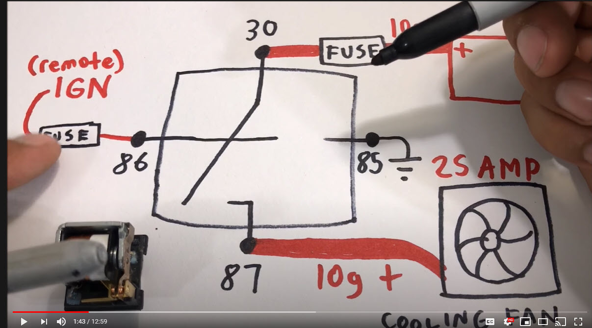
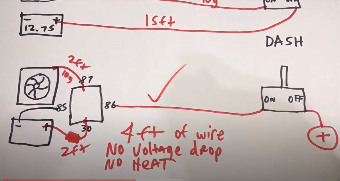
This is an awesome video explanation on Automotive Relays. Many Nissan Maxima members like to install high-performance cooling fans. If not properly installed using a relay, you can risk burning the wiring out. This has happened to us various times. The video below will help you understand how to do it correctly.
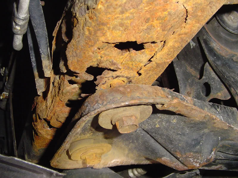
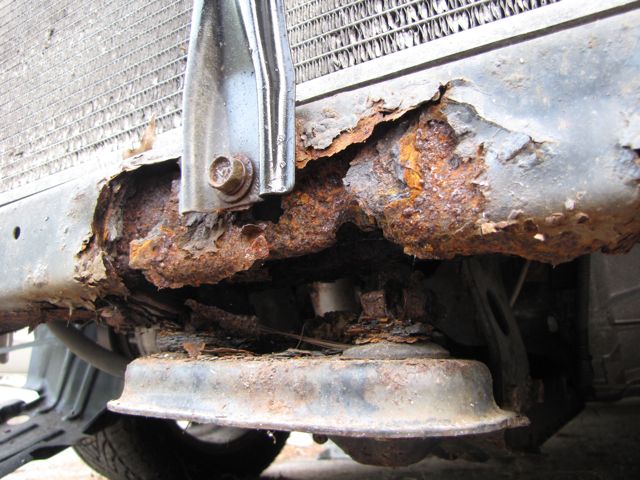
As many of you may know the radiator core support is a known “weak point” on the A32 chassis. This is an extremely common issue among A32’s from “wet” states. This thread will address a number of key points with these issues
Signs of a bad radiator core support
How to replace said radiator core support
And why you shouldn’t use a cheap radiator core support
I: Let’s start off with spotting a failing core support (NOTE: The images shown are of very, very badly rusted supports)
II: We move on to How To replace the core support and what is the proper parts to be used and where you can purchase them.
To correctly replace the core support, the old unit will need to be cut out and the new unit will need be be bolted and welded in place..This job is definitely not one of the easier things to do an A32 and will likely need to be done by a professional or a fairly knowledgeable DIY mechanic with access to air tools and a welder.
Their are two common methods to to replacing the core support; one is replacing just the lower support (under the radiator) and the other is replacing the entire front core support. Either of these parts can be sourced at your local Nissan dealer or through a reputable online dealer such as Courtesy Nissan Parts.
PARTS
The part number through Courtesy for the entire support is 62500.
The part number through Courtesy for the lower support is 62530M.
III:
We will move on to why you should buy an OEM core support and not a cheap piece off of ebay or rockauto. This is one of those things that “if it sounds too good to be true, it probably is”…meaning that $50 core support on eBay may sound like a steal of a deal right now, but 3 months down the road when you notice your engine cradle is sitting 3 inches off the ground and you have to pay to do all of this work again, you will wish that you had just spent the extra money to begin with because in the long run an OE piece is going to be the cheaper AND better investment.
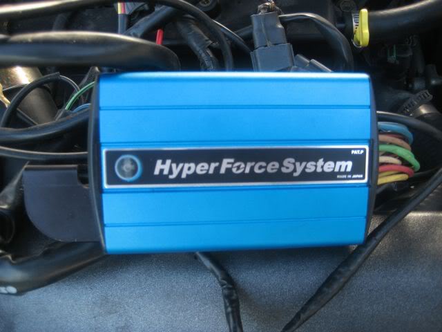
The Sun Auto Hyper force is an ignition enhancer, in which provides greater throttle response and smoother engine performance by providing optimal spark duration and maximum voltage output. This product is very effective at higher revs where a normal spark would diminish, specially on boosted 350Zs/ G35s. It prevents high rpm ignition miss that reduces peak power and the longer duration allows the Twin Power to improve lower RPM throttle response and torque.
The Sun Hyper Force system is the next generation high-efficiency ignition tuning and strengthening system. It works by absorbing all back electromotive force, which aids to improve plug voltage and promote complete combustion by producing higher coil efficiency. Also, the Sun Hyper Force System eliminates any ignition performance loss due to decreased electrical current under heavy throttle. Since ignition efficiency over the entire revolution range improves, available torque and acceleration response improves; this efficiency enhancement also contributes to better fuel efficiency and a reduction of harmful emission.
Features
Increased horsepower
Increased torque
Better gas mileage
Improved throttle response
Longer battery life
Improved battery efficiency
Reduced emissions
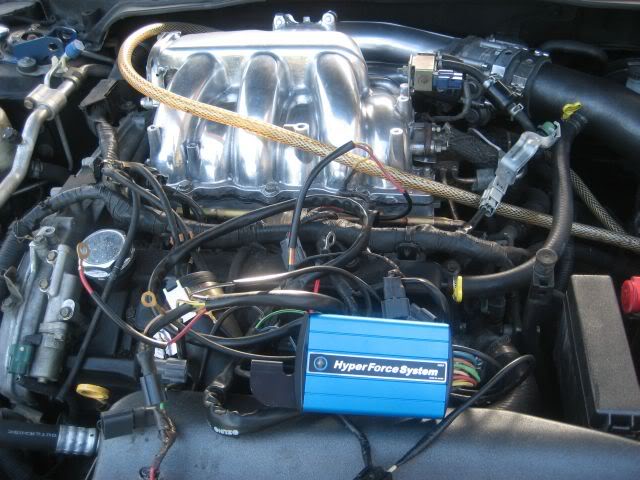
This is a plug and play system, you connect the plugs from the coilpacks into the harness and there is a plug there goes back into the coilpacks.
6 Ground wire and 1 positive to the battery from the Blue box.
It flashes Blue LED light so that you know everything is up and running.
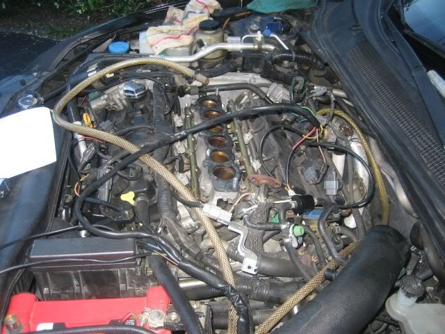
Uncovering the CF cover
After these it got really dark so i didn’t bother taking anymore pics, I need to clean up the wires and mount the box near the firewall , this system was design for the 350z but will work for our cars.
If you know how to do your own spacers or change your spark plugs you can do this upgrade. This is how I would rate the difficultly.
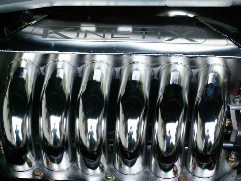
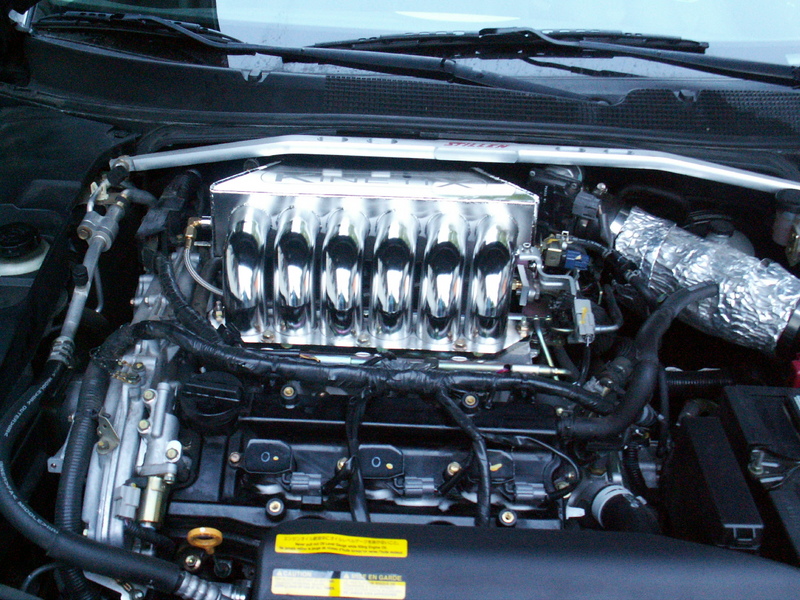
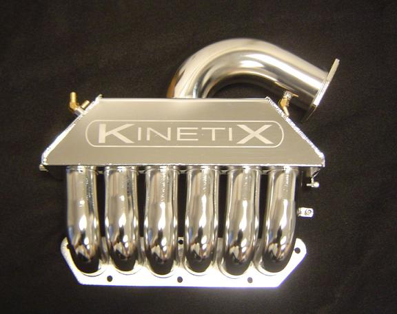
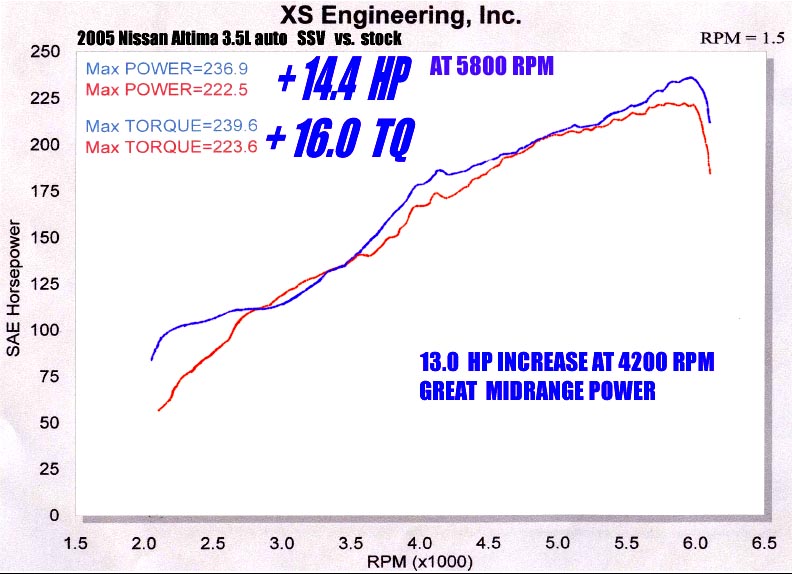
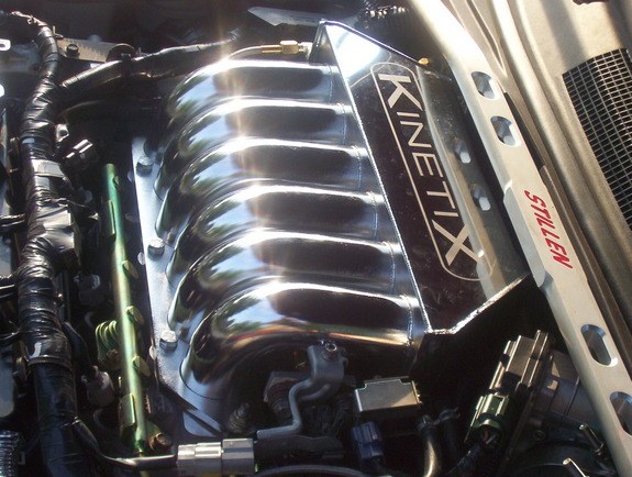
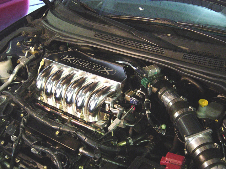
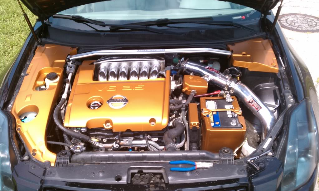
The procedure for removing the OEM intake and replacing it with the Kinetix was fairly straightforward. With basic hand tools, I did the job at a casual pace in under 2 hours.
Tools Needed:
Allen wrench (supplied with manifold)
10mm, 12mm, and 14mm wrenches and sockets
Flat blade screwdriver
1. Disconnect battery and remove engine cover with Allen wrench
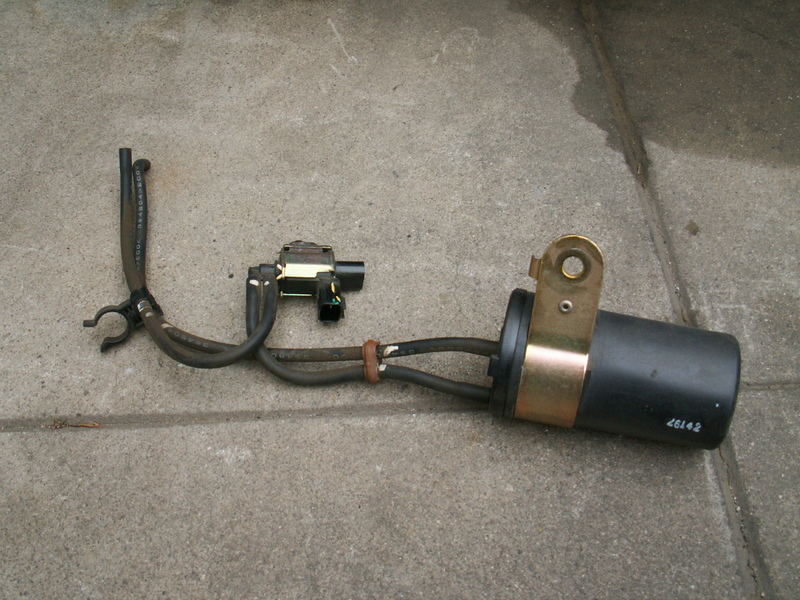
2. Remove attachments on the manifold, including this canister shown here:
3. Remove air intake
4. Remove throttle body with 4 allen bolts. Now is the time to clean the throttle body.
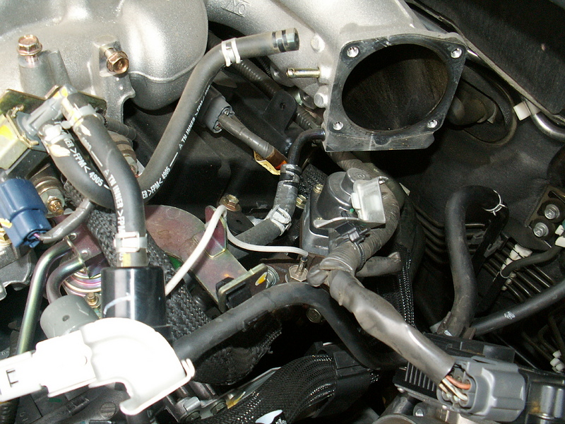
In this picture, the disconnected hose is a vacuum hose. But the hose below, that is still connected, with the black fitting is a COOLANT hose. Be careful when remove this hose as coolant leaks out. You can also see the EGR hose which has black braided material, which is right below the two vacuum hoses near the left center of the picture.
5. The bolts at the back of the manifold are now accessible . .. barely. They are hard to get to, and you have to have a good touch. I believe they are 12mm, and there are two of them.
6. Once all hoses and front brackets are removed, and the rear middle bracket is disconnected, the EGR tubing must come off. Its very stiff and hard to take off.
7. Now is the time to undo the manifold nuts and bolts. Do it in a cross pattern and start it a 1/4 turn at a time until they are loose so you don’t warp anything. There is one more bracket to remove, but its easier to remove it when the manifold is raised a bit.
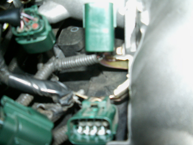
8. The bracket on the passenger rear side of the manifold is very hard to remove because of the lack of space and the angle. Its a 10mm bolt head. Here is a pic of the green connectors that attach to it:
The manifold should come clear from the car.
Installation:
1. Unscrew the plug from passenger side of manifold. Screw in the fitting from the EGR hose; only the fitting, NOT the hose yet. Make sure its positioned in line where the hose will eventually connect.
2. Lay the hose across, behind the lower manifold. Connect the braided EGR hose to the OEM stiff pipe. I reused the gasket but you should get a new one.
3. Install manifold. Tighten in cross pattern so nothing warps.
4. Connect the EGR braided hose to the fitting in the manifold.
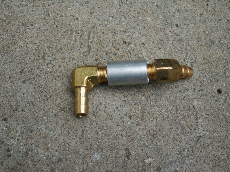
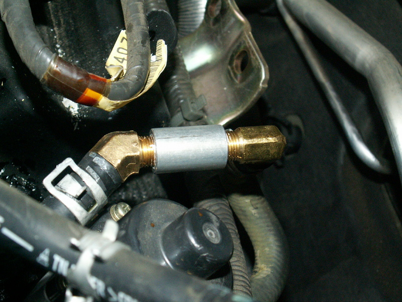
5. The coolant hoses need to be joined together. Identify the coolant hoses (green fluid dripping out) and join them together with this fitting:
After its connected, it should look like this:
6. Connect hoses, the throttle body and air intake. This should be fairly obvious if you’re careful when you disconnected things.


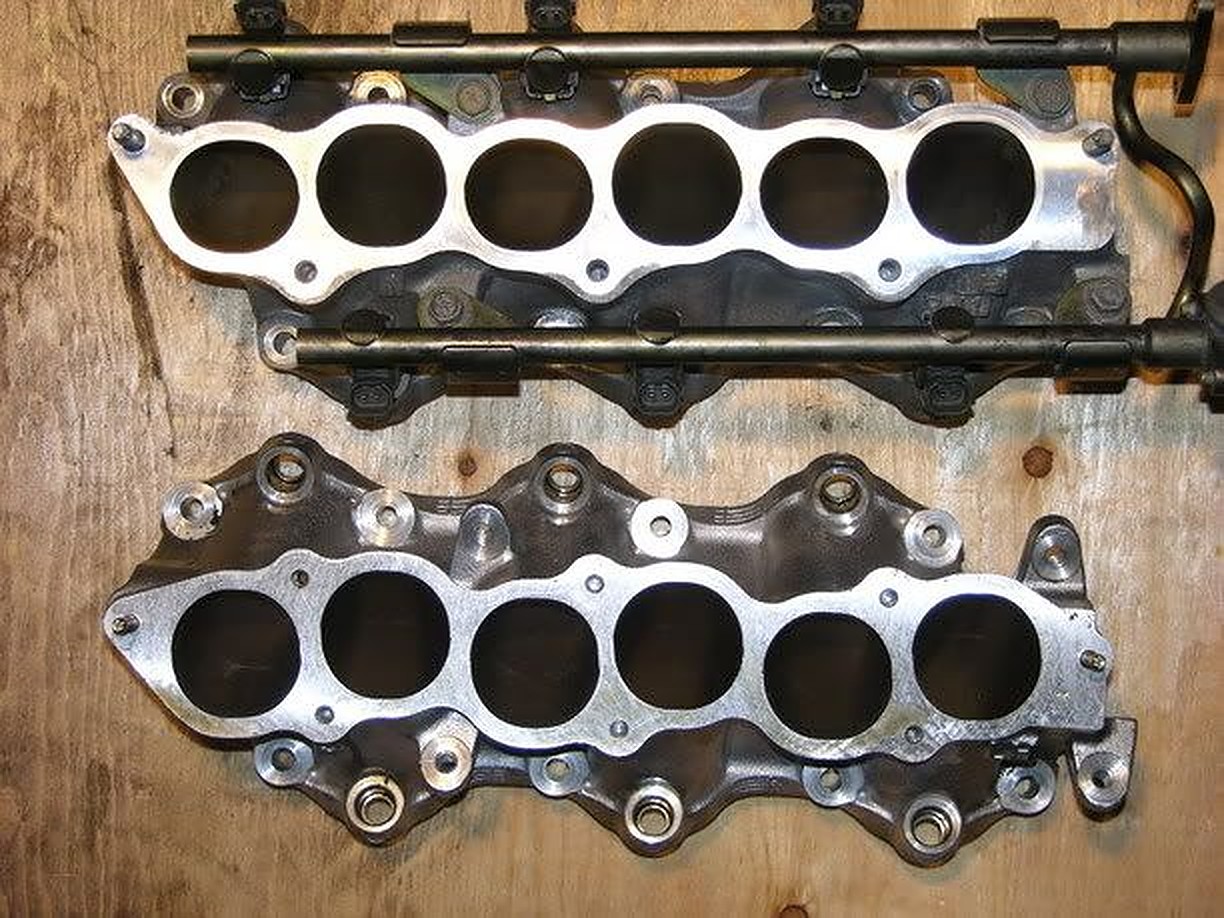
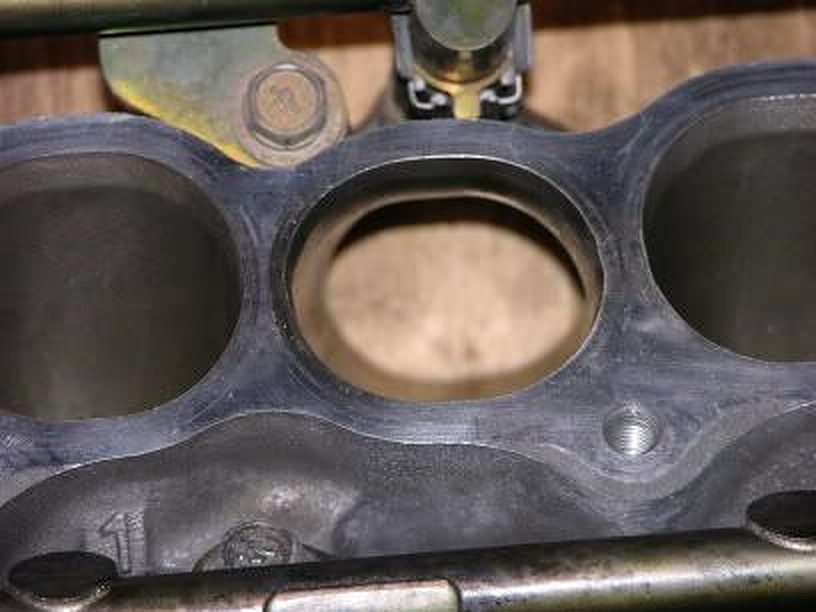

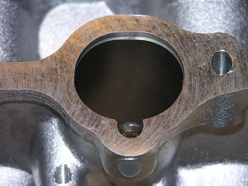


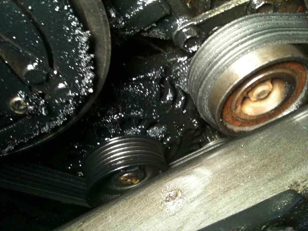
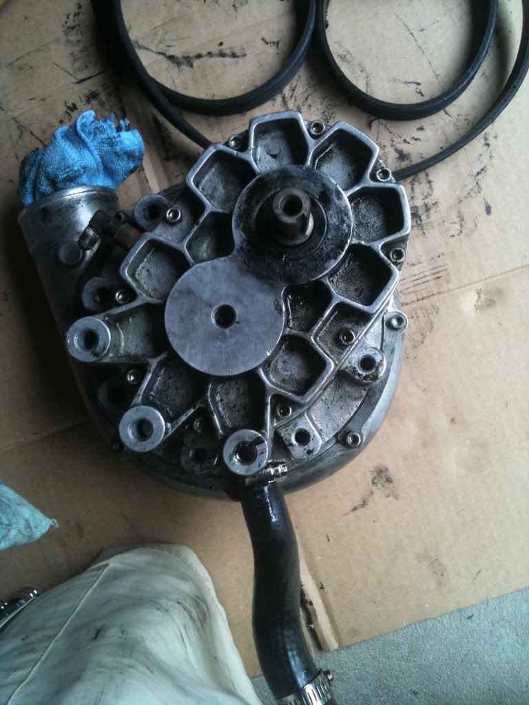
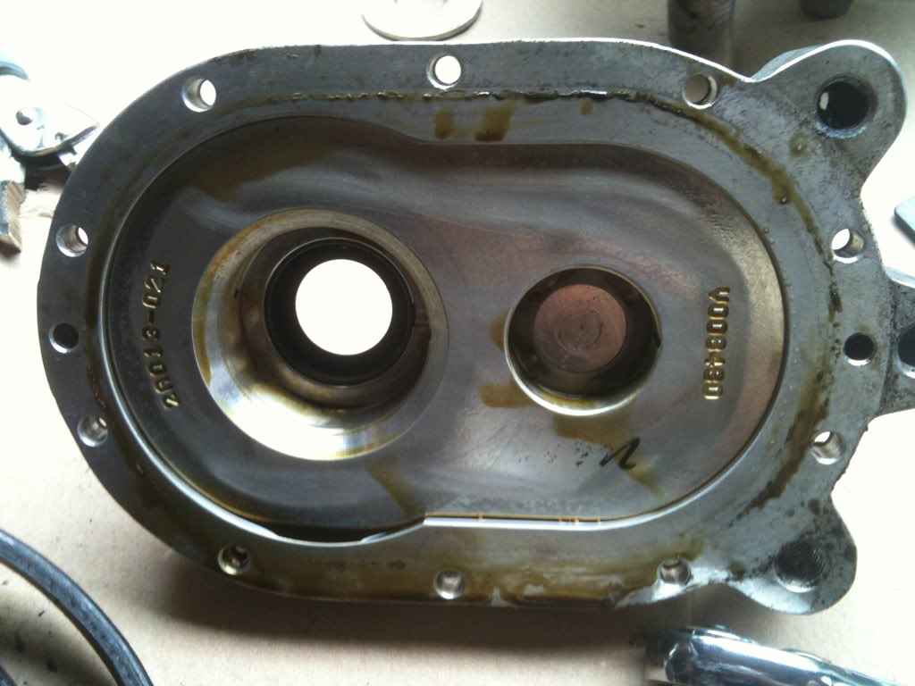
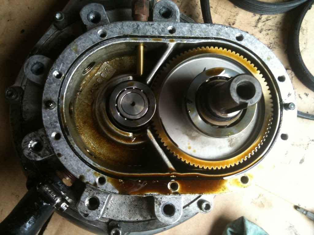
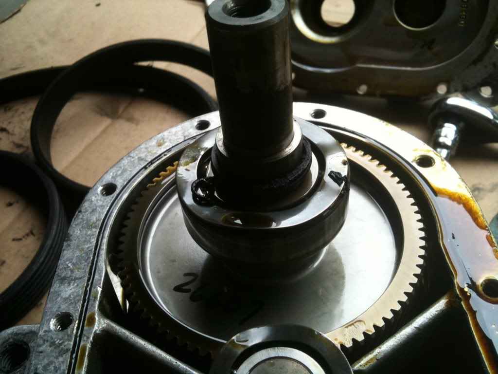

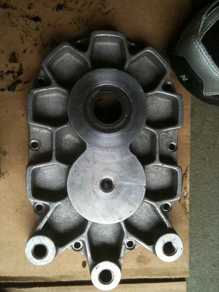

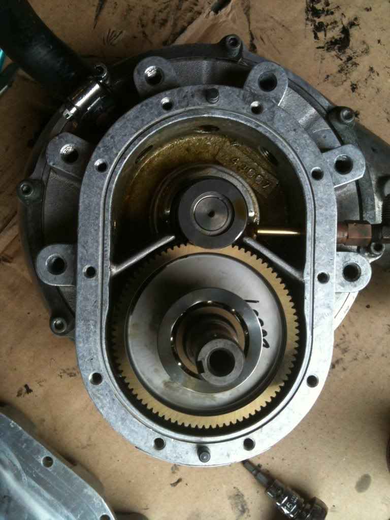
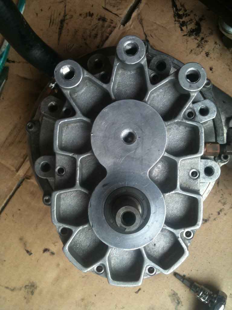


 Figure 2. TCM harness and connections.
 Figure 3. Extend the wires on the clutch interlock switch harness to reach the TCM connector.
 Figure 4. ASCD brake pedal cancel switch disconnected and wires from the ASCD brake/clutch pedal cancel switch harness.
 Figure 6. Manual R/N switch harness and automatic inhibitor harness become one.
")