Ok guys after spending a lot of time and money last year I ended up using an automatic shifter dubbed shift-fast for my automatic transmission.. It is just some relays connected to a RPM switch (Emanage\UTEC\MSD). It works fine, it allows me to shift at any RPM I desire automatically which is great for the track. However it doesn’t control the converter lockup and I have to use the exact same shift RPM for each gear. The trans takes longer to shift from 2-3 than from 1-2 so the RPM is higher for the 2-3 shift, not exactly what I want. I was trying to come up with another way while watching the snow fall and although using 2 window switches would solve part of the problem its just more wiring and relays. Grey99 has also spent a lot of time working on the automatic shift-fast and has his own version working quite well.
I decided to do some searching to see if anyone else had come up with an easier solution. After a few hours of searching I ran across a device made for the automatic Supra that does it all. Suprastick V4. Individual shift points for each gear, torque converter control for each gear, 2 maps (one for race one for normal), manual shift mode using paddles or switches, shift light, automatic protection from downshifting. It is a complete standalone TCU programmable via a PC. I have been in contact with the President and Chief Design Engineer Garrett Rowe who assures me he can easily change the code so it will work with the Maxima shift pattern.
The Suprastick manual can be downloaded here: SSv4.6 – Manual
I checked the G20 FSM and your trans in the same number of solenoids and same shift pattern as the Maxima/Altima so this will work.
Ok here goes. Does the SupraStick work? Yes, exactly as advertised. It comes packaged like this.
There are a number of programing screens to set it up but this is the most important one. There are 2 maps for auto shifting one for track and one for street or whatever. Just insert the speed you want it to shift at with the applicable throttle opening and bingo it does it. I have 2 switches one to select map 1 or 2 and another to select manual or auto shifting. I use the cruise control buttons for the manual up down shifts and it works great. One of the options is to set an RPM limit for downshifts, whatever you set this RPM for the trans will not downshift if it is exceeded to save your trans.
Does it work at the track? I waited until today to post this. There were around 24 cars in the field and I managed to win it all. Not too bad for an old guy that was paralyzed from the neck down 8 months ago. Youth and skill can be overcome by old age and treachery every time.
This is a pic of the display which is available for approx $35 to show mode, gear, throttle opening, speed and rpm.
This mod forces the transmission to shift at FULL Line Pressure at all times the switch is on. A WOT (Wide Open Throttle) switch is best suited for this purpose because the part throttle shifts are extremely harsh and could damage the transmission.
The drop resistor mod disconnects the dropping resistor in the transmission control circuit. This forces the transmission to run a maximum line pressure. This makes the shifts VERY hard. Even an otherwise stock car will chirp the tires on the 1-2 shift with this mod.
The downside is that part-throttle shifts are very jerky. The solution is to wire a Wide Open Throttle (WOT) switch that disconnects the resistor only at full throttle.
Reference Info:
The line pressure is varied according to throttle opening, RPM etc so that the more power you put down the more pressure is produced so that theoretically the shift time remains the same.
The more HP you put out the slower the trans will shift if you don’t increase the line pressure, so they have designed it to be suitable for 95% of the driving public.
What I am trying to do is have maximum line pressure at WOT ONLY, I like the way it shifts under normal operation, thats why I don’t have a VB mod. Maximum line pressure gives the fastest shift possible and saves the clutches from burning unecessarily. However I don’t want maximum line pressure at part throttle as the shifts are very jerky because the engine is only putting out very little HP.
The stock design does not put out maximum line pressure at WOT and the Drop Resistor Mod does.”
Installation Pics
Ok here is where the drop resistor is located. Front side of the drivers side strut tower.
There is a connector with two wires attached to the resistor. The electrical drawing of the drop resistor looks like this. You must cut one of the wires, doesn’t matter which one but cut it at least 2 or 3 inches from the connector so you have room to strip and connect to it.
Strip a small section on either end of the wire you just cut and attach a wire to each end by soldering or use a connector. Run the two wires to a switch. Either a WOT micro switch (preferably) as per the picture or a manual switch.
I have a small L bracket I made that attaches it to the intake manifold bolt closest to the throttle body.
Keep adjusting the switch position until the throttle hits it just before or when it hits the WOT position. It is imperative that this switch be a Normally Closed (NC) switch so the circuit is always made until you hit WOT at which point it opens and effectively disconnects the drop resistor from the circuit.
You can do the same thing by running the two wires to the cabin and hooking to manual switch (5 amp rating or higher) but I much prefer the WOT switch because you never have to worry about turning it on or off. You have enough to think about when racing without another stupid switch to turn on and off.
The micro switch I use is rated at 10 amps and I got it from an appliance shop where it is used in a microwave.
Most switches of this type are Normally Open (NO) and this will NOT work.
The Suprastick manual can be downloaded here: SSv4.6 – Manual
Tools Needed
Wire stripper
Wire taps
Wire quick connectors (slide or bullet style)
Soldering iron
A lot of wires
Additional Parts Needed:
DB9 male to DB9 male serial cable (for LCD screen)
Null modem adapter (for LCD screen)
USB to serial cable
16×2 LCD screen with serial port (optional but recommended)
Shift light (optional)
Two SPST toggle switches
Before you begin, disconnect the neg terminal of the battery.
Installation Steps
Step 1:
Remove shifter trim, ash tray, and the whole middle piece (one w/ the cupholder and armrest) for easier access to the TCM.
Step 2:
Locate the TCM, should be directly in front of you, you can’t miss it. looks like the ECU. remove clear plastic cover. here you will need to identify just 2 wires, one for solenoid A and other for solenoid B. these are the solenoids that controls your gear shifting.
Step 3:
Intercept wires 6 and 7 like so:
*Optional* If you want to let the suprastick control the TC lockup feature, you will have to cut wire #5 on the TCM and connect it to wire #15 on the suprastick. Then you will have to find an adequate brake signal source to tap into.
Step 4:
Finish wiring all the other wires
Suprastick:
wire 1: wire to ground source
wire 2: wire to a SPST switch, other end to +12V source
wire 3: tap into pin 24 on ecu
wire 4: refer to step 3
wire 5: refer to step 3
wire 8: Tap into pin#28 on the middle harness behind the gauge cluster.
wire 9: tap into pin 23 on ecu
wire 10: tap into pin #1 on the ASCD, located above the gas pedal (EL 151 of FSM)
wire 11: tap into pin 5 on ecu
wire 12: optional, refer to step 3
wire 13: refer to step 3
wire 14: refer to step 3
wire 15: optional, refer to step 3
wire 16: optional
wire 17: tap into pin #2 on the ASCD, located above the gas pedal (EL 151 of FSM)
wire 18: Optional
wire 19: Optional
wire 20: wire to a SPST switch, other end to a +12V source
For Wires 18 and 19, again this is optional. this is for the drop resistor, to run maximum pressure for the tranny line. i have mine connected to another toggle switch but if you want the suprastick to control it, just run it inline with the two wires on the drop resistor.
Step 5:
* Now for the programming. I’m not going to go too much into detail for this part b/c that’s what the manual is for. But there are a couple things that i need to mention that will save you time and headaches.
* For the initial setup, when your setting up your hyperterminal, select the correct COM port and follow all the settings. One thing you want to keep an eye on is the “hardware flow control” setting. try setting the flow control to hardware first and see if the hyperterminal screen corresponds when you push 1. if it doesn’t, disconnect, go back into the flow control setting and turn hardware flow to NONE. Now it should work.
* Couple things for the Vehicle settings. One advice is, keep the speed sensor teeth to 20 and just adjust the rear end ratio until the spd display matches the speed on the gauge cluster. Best to do this w/ 2 people, one driving at a constant speed of say 20 mph, and the other adjusting the rear end ratio.
* Also, remember to correctly adjust the shift pattern under the shift solenoid setup. by default its for the supra.
* for the automapping, the stock ecu defines your driving style, and not the other way around. The SSv4 will learn the stock ecu shift points if you have the stock ecu hooked up to it. Just drive the car once through the largest throttle range possible for as large a speed range possible and you are done. It is usually just quicker to tweak the base map provided, however.
That should do it. if anyone is interested in doing this and have any questions, please don’t hesitate to ask.
I started pulling my tranny today so I can change the throwout bearing and I stripped the drain bolt. luckily I found a video on Youtube on how to remove it with a chisel and punch.
I had ordered 2 new Smart-O R23 M18x1.5 drain plugs ahead of time for whenever I was going to need to change the gear oil in my transmission, the plug uses a 19mm wrench instead of a 10mm Allen bit.
OEM Driver Side Part Number: 38342-81X00 Alternate Non-OEM Part Numbers: Timken / O’Reilly – 710118 Part Description: SEAL-OIL, Nissan Driver Side Output Shaft Seal / Differential Transmission Case Price: $8.00-$9.00
OEM Passenger Side: 38342-81X01 Alternate Non-OEM Part Numbers: Timken / O’Reilly – 710124 Part Description: SEAL-OIL, Nissan Driver Side Output Shaft Seal / Differential Clutch Housing Price: $8.00-$9.00
Input Shaft Seal: 32113-03E00 Part Description: SEAL-OIL, Nissan Input Shaft Seal Price: $8.00-$9.00
Please Note: This is in reference to the 6-Speed Manual Maxima’s.
What does HLSD Stand for?
HSLD Stand for Helical Limited Slip Differential
What is it and what does it do?
It is a limited-slip allowing power to be fed to both wheels when wheel slippage is felt. You can feel it kick in when you burn out….you ever notice how cars tend to turn to one side…well on yours…you should just pull straight.
How do you know if you have a factory 6-Speed HSLD?
The identification for the engine and transmission is located under the hood on the firewall in the form of a thin aluminum plate. The engine code will read: VQ35(DE)
If you have a 6 speed with an open diff the code will be: RS6F51A
The last letter A means open diff. Open diff is just the regular factory transmission without HSLD.
If you have a 6 speed with a Helical Limited-slip Differential the code will be:RS6F51H
The last letter H means Helical.
Important Note:The 6-Speed Manual Axles are the same for either open diff or HLSD. The automatics are the ones that are different.
I did a 5 speed swap two weeks or so ago and there was a lot of time spent wading through the FSM pages to make sure the electrical system of the automatic chassis was compatible with the manual transmission, and the functionality of a manual chassis. This is a guide I came up with the try to easy the confusion when swapping a automatic transmission out for a manual one. I followed the procedure outlined below and used a 1997 manual ECU in my 1997 automatic chassis and can happily report that I have no CEL.
I. Introduction
This is a guide to those of you who wish to swap the automatic transmissions out of your fourth generation Nissan Maximas. It will walk you through the procedure to convert the electrical system. There are four areas that must be addressed in order for your car to be as close to stock as possible, electrically and functionally speaking, after the swap:
As always, when working on the electrical system of your car, disconnect the battery.
II. Reverse Lights
Relevant FSM section:
EL – Exterior Lamp – Backup Lamp
In order to pass safety inspection in many states, the reverse lights must come on when the vehicle is placed in reverse. On the automatic this is achieved thought the inhibitor switch which is mounted to the front of the automatic transmission. On the manual version of the car, the reverse/neutral (R/N) switch handles this. When reverse is selected, the switch completes the circuit and sends battery voltage to the reverse lights.
I used the R/N switch harness from the manual version of the car, and soldered it in place where the inhibitor harness used to be. You will notice on the R/N harness you have two think wires and two thin wires. You will need to connect the thick wires in this step. First thing is first, cut off the two connectors that plugged into the inhibitor switch when the automatic was in the car. Next, locate the green and green/white wires on the inhibitor harness. The green wire supplies battery voltage, and the green/white wire runs back to the reverse lamps. Luckily for you, the wire colors on the R/N switch harness are the same. Using the thick green and thick green/white wires on the R/N harness, connect them to the green and green/white wires on the inhibitor harness (Figure 1). I have used shrink wrap tubing to insulate the joints, but electrical tape will work as well.
III. Clutch Interlock Switch
Relevant FSM section:
EL – Start
AT – Wiring Diagram
In order to prevent you from starting the car in gear, the vehicle is equipped with a circuit that will only energize the starter solenoid if it detects you are in neutral or park. Again, with the automatic, this is accomplished based on which contacts of the inhibitor switch are connected. On the manual, this is accomplished by sensing when the clutch pedal is fully depressed. To keep this functionality after the 5 speed swap, you must connect a wire in the inhibitor harness to the clutch interlock switch (switch that senses when the clutch is fully depressed). The other side of this switch must be tied to ground, so that when the clutch is fully depressed, the wire on the inhibitor harness is grounded. Fortunately, when you do a 5 speed swap, you will have a bunch of wires left over that are unused. This will allow you to easily run a wire to from the engine bay to the cabin by using some of those unused wires. For this task, I have used a yellow/blue wire to complete the circuit to the clutch interlock switch (Figure 1.) This yellow/blue wire used to tell the TCM (Transmission Control Module) when the vehicle was in drive. Connect the green/orange wire from the two conductor side of the inhibitor harness to the yellow/blue wire, on the seven conductor side of the harness.
The next step is finding where this wire comes out in the cabin. The TCM is underneath the BCM, directly in front of the shifter. Its harness looks similar to the ECU harness in that it has a 10mm bolt securing it. Find the yellow/blue wire and cut it from that harness (Figure 2). It will be in position 18. Also, find one of the black ground wires, and cut it as well. This will be the ground that one side of the clutch interlock switch is connected to. The grounds are positions 15 and 48. Next, you will need the clutch interlock switch from where ever you got the clutch pedal. It will be in a harness with the ASCD brake and clutch cancel switches, along with the brake light switch. Remove the clutch interlock switch connector from this harness and extend the wires on it (Figure 3). Add enough so that they reach the TCM connector with about six inches to spare. At this point I wrapped electrical tape around these wires to keep the harness looking stock. It also keeps the wires in a bundle, which makes them easier to keep out of the way. Route these wires under the dash and around into the center console. Now connect one of the wires from the clutch interlock switch to the yellow/blue wire from the TCM harness. Connect the other wire from the switch to the black ground wire on the TCM harness (Figure 2).
IV. Park Neutral Switch
Relevant FSM section:
EC – Park Neutral Position Switch
AT – Wiring Diagram
Nissan engineered the electrical system in the fourth generation Maxima to be able to sense when the car is in park or neutral. If you have been paying attention up to this point you would have probably guessed that in the automatic, this is done by the inhibitor switch in the P or N position. Of course, we removed the inhibitor switch. To take its place in the manual, the reverse/neutral switch is used. Look back under the hood and find the additional two wires coming from the manual R/N switch harness. They will both be thinner than the two connected for the reverse lamps, and will be green/white and black in color. Now, locate the two wires coming out of the inhibitor harness that are pink/black and purple/white. I connected the wires with the white tracer together (purple/white to green/white) and I connected the pink/black to black (Figure 1). Again, find the TCM harness and connector, and cut off the pink/black (position 17) and purple/white (position 16) wires. Also, cut off the other ground that you did not use in step III (position 15 or 48). Additionally, you need the wire that runs to ECU pin 22 form the TCM connector. This wire is green/orange, and is in position 13. You now need to connect the wires from the R/N switch to ground on one side, and the ECU on the other. Connect the pink/black wire to the ground wire from the TCM connector, and connect the purple/white wire to the green/orange wire that runs to the ECU (Figure 2). Now, when the transmission is in neutral, ECU pin 22 will be grounded.
V. ASCD Cancel Switches
Relevant FSM section:
EL – Automatic Speed Control Device
Automatic Speed Control Device is a fancy phrase for “cruise control”. In order for this system to function properly, it must disengage when the clutch is pressed or the brake is applied. Of course in a car that used to be an automatic, there is no clutch, so only the brake pedal has a switch. Because you will be adding a clutch pedal, you will need to sense that as well if you wish for the system to function properly. You will need the ASCD pedal switch harness from a manual car. This harness is easily identified as the one that plugs into the pedal switches. You should have already used a portion of it in the Step III when you hooked up the clutch interlock. You can remove the brake light switch connector from the harness, as that is not used (it is the larger one). Now, unplug the ASCD brake cancel switch from its connector, and remove that connector from the car. Connect the wires running to the ASCD brake/clutch cancel switch harness to the wires that used to connect to the ASCD brake cancel switch. Effectively what you are doing is wiring these switches so that if either the brake of clutch pedal are pressed at all, the ASCD system will turn off the cruise control until you reset it (Figures 4 and 5).
VI. Conclusion
If you have followed the directions outlined above, you should have successfully completed the electrical portion of the 5 speed swap enabling you to have all the functionality of the 5 speed car in your automatic chassis. If you have also received a manual ECU from a car compatible with your model year’s emissions, you should be able to complete your swap CEL free.
Figure 1. Inhibitor and R/N switch harness
Figure 2. TCM harness and connections.
Figure 3. Extend the wires on the clutch interlock switch harness to reach the TCM connector.
Figure 4. ASCD brake pedal cancel switch disconnected and wires from the ASCD brake/clutch pedal cancel switch harness.
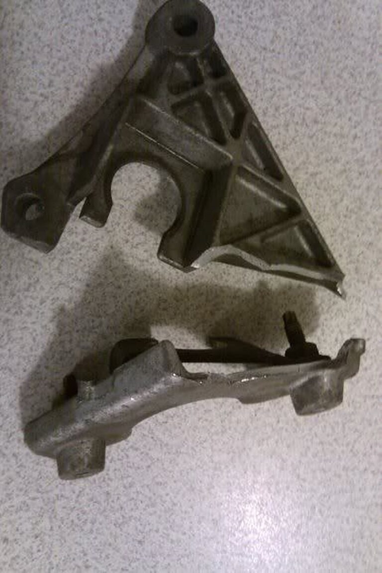
If you recently broke your shift linkage bracket, below is the information you need for a replacement. And while you’re at it, stop shifting too hard lol.
The one you want is the 6thgen Nissan Maxima bracket. It’s interchangeable with the 5.5 5thgen as well.


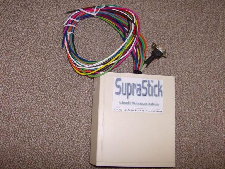
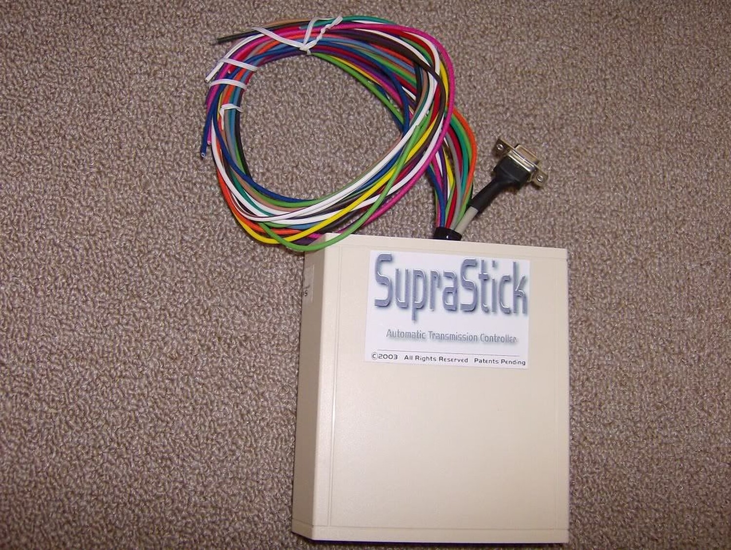


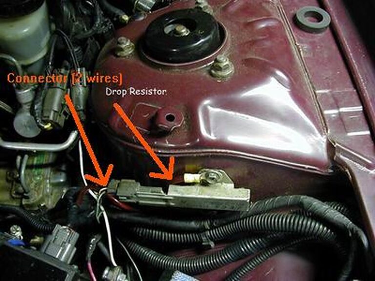


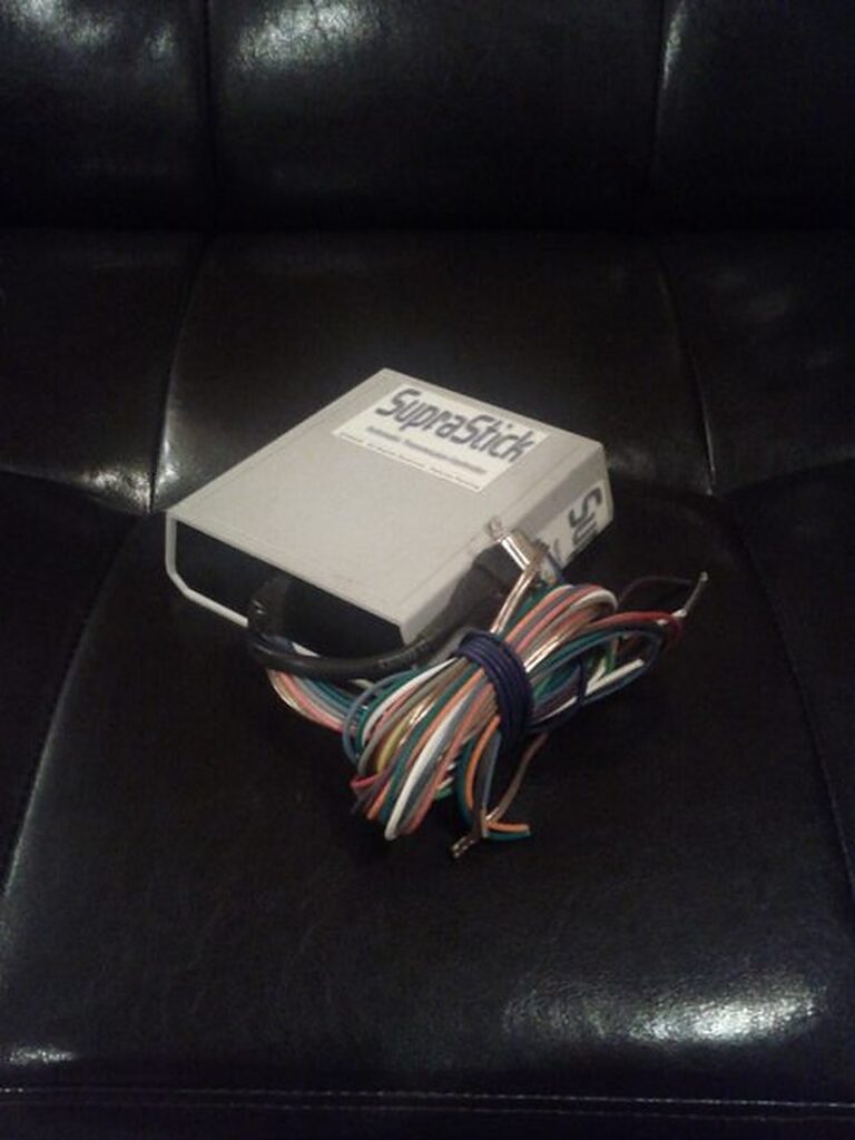
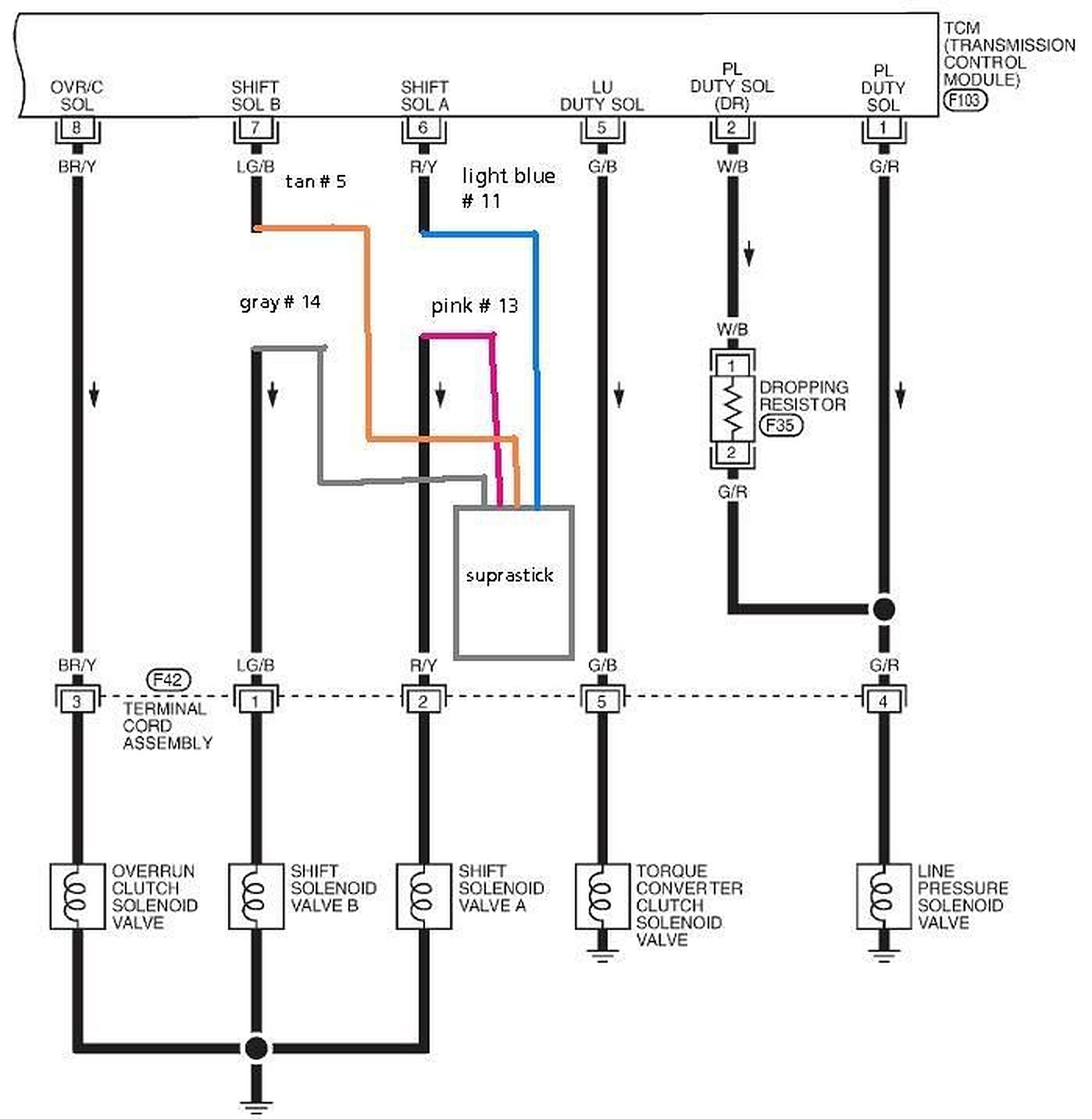
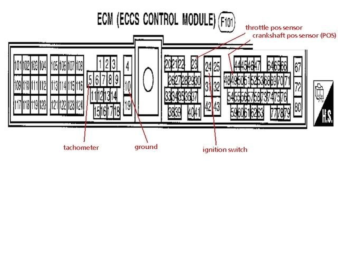
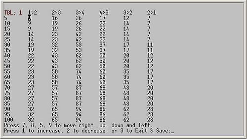
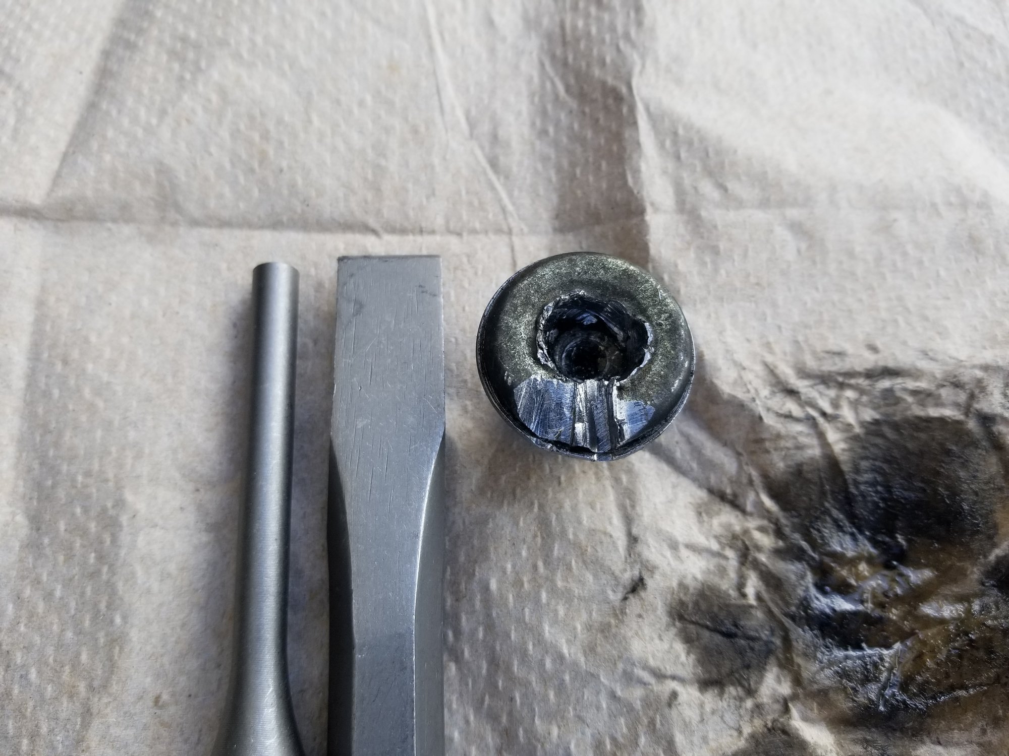
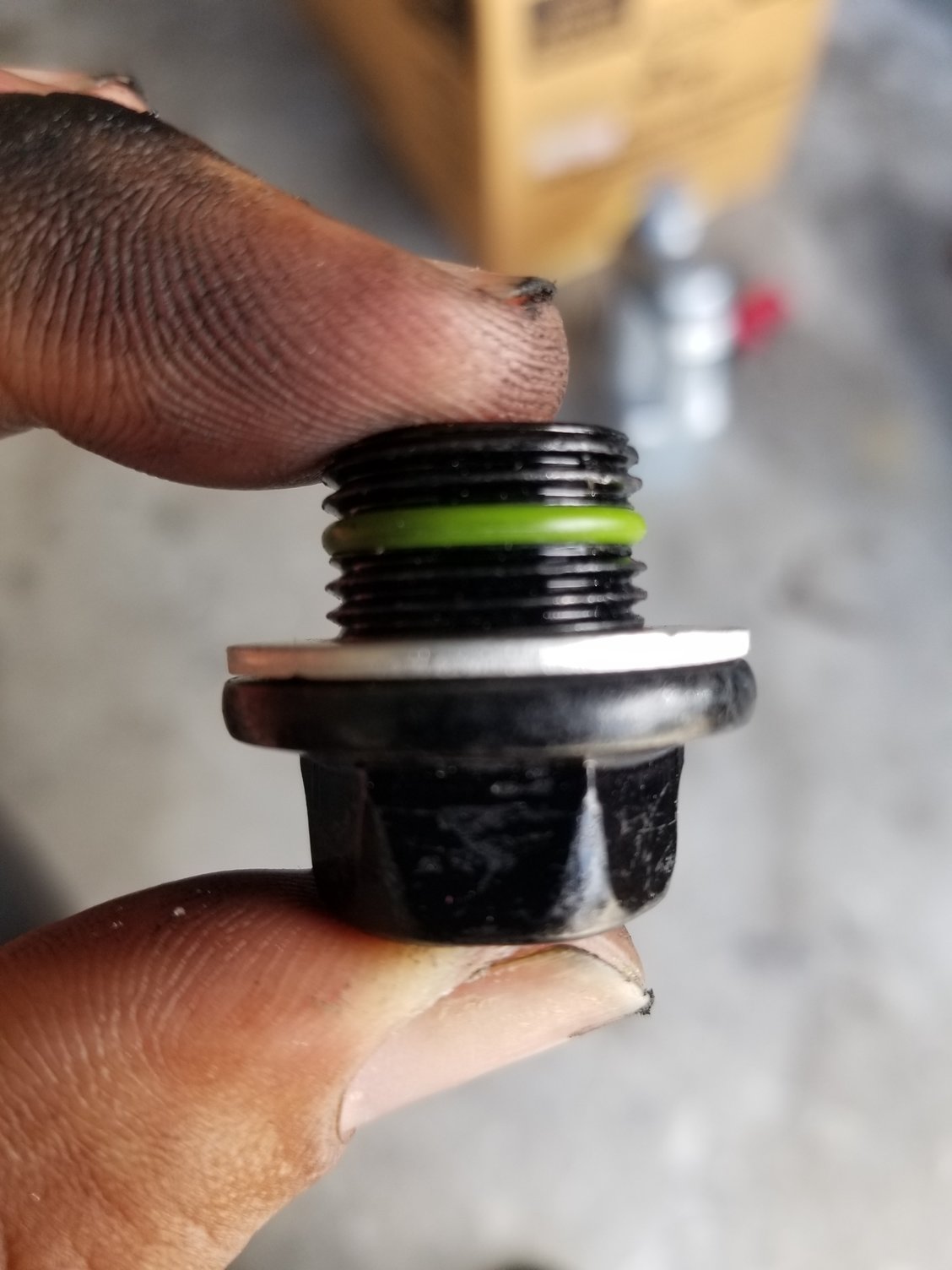
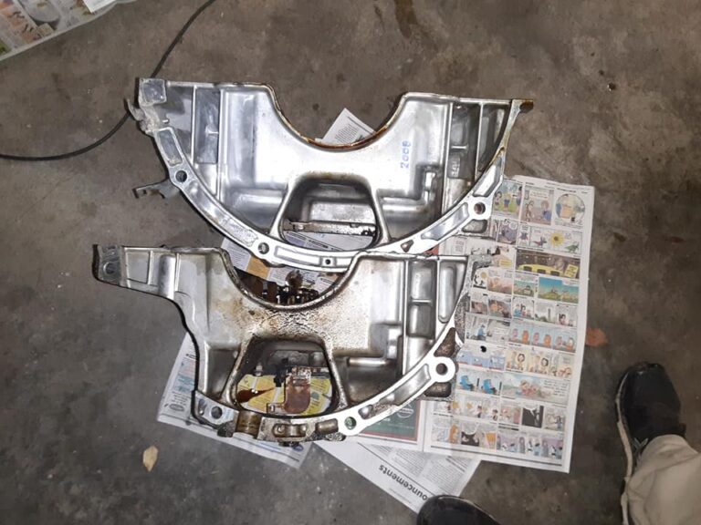

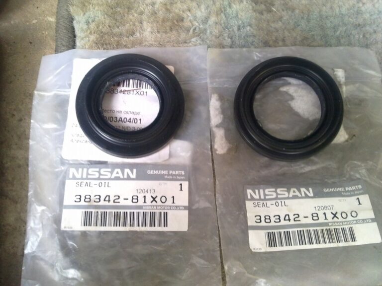
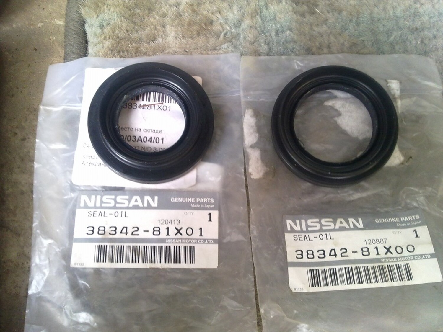




 Figure 2. TCM harness and connections.
 Figure 3. Extend the wires on the clutch interlock switch harness to reach the TCM connector.
 Figure 4. ASCD brake pedal cancel switch disconnected and wires from the ASCD brake/clutch pedal cancel switch harness.
 Figure 6. Manual R/N switch harness and automatic inhibitor harness become one.