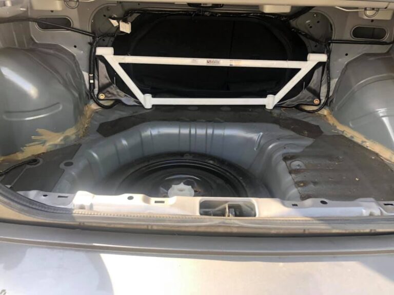
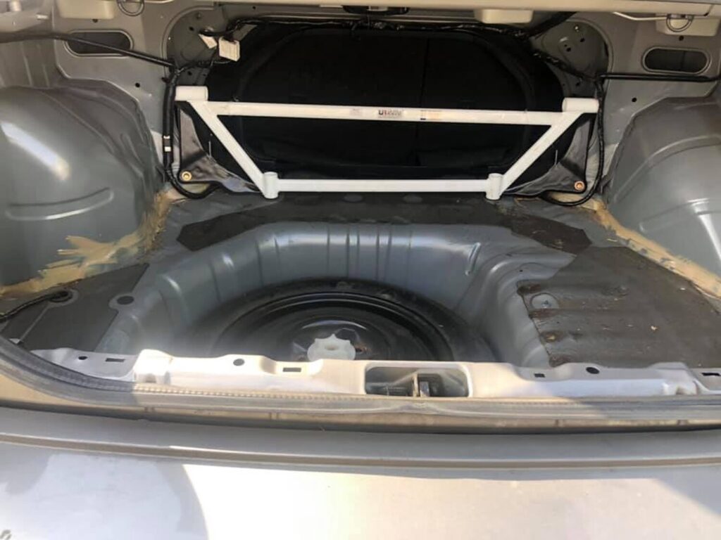
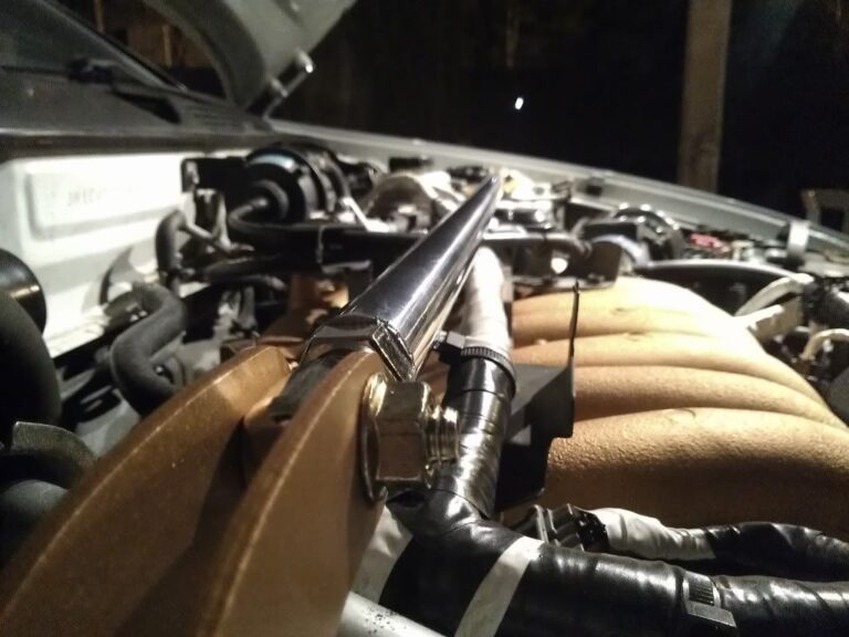
Bought an eBay front Strut bar. Was somewhat iffy from the pictures on eBay, but the quality was much better than I expected, especially for the low low price of $30.00 shipped. I took it apart and painted it to match the rest of my accents in the engine bay.
If you don’t already have a strut bar and don’t have the $100.00+ in your bank account for the Stillen strut bar, I highly recommend one of these. Even if it doesn’t work as well as some of the name-brand ones, it still makes the engine bay look fancy.
Nissan no longer lists this bushing however, the 03-08 350z bushing is available and is an exact fit. Part # 54445-4P000.
I did this after installing my headers with the Y-pipe removed.
Time 1-2 hrs
Tools Needed.
1. Jack and Jack Stands.
2. You will need 2 (two) 19mm Combination Wrenches
3. 19mm Socket, wobble extension, and Flex head Ratchet (my preference)
4. Short handle 2lb sledge hammer.
5. Large Concrete Chisel
6. Anti-seize.
7. 6 inch long piece of 2X4 wood
8. Pair of Channel Locks
9. 10mm Wrench
9. 1 Sharpie to mark the location of the bracket on the rack
10. Don’t forget to buy new exhaust gaskets.
Steps:
1. Secure the car on Jack Stands.
2. Remove Passenger side tie-rod end from steering knuckle.
3. Remove Y-pipe. Before you continue, mark the bracket location on the rack
4. Remove the 19mm nut and bolt from the top of bushing bracket.
This is a bit tricky, room is tight, I used the 2 combination wrenches here.
5. Remove BOTH of the bolts securing the rack to the frame. They come out front to back and the nuts are part of the subframe. (There may be a bracket that stabilizes the powersteering line to the rack, its a small metal bracket with two rubber bushings secured with two 10mm bolts)
6. The bracket may come right out but if it is tight like mine was it’s gonna be tough. I took my large concrete chisel (10″ long, 3″ blade) and hit the under side of the bracket a few (or ten) times.
7. Next is getting them suckers apart. I also used the concrete chisel for this by spinning the brackets backwards and hammering the 6″ piece of 2X4 between the stabilizer bar and the body so the top side of the bracket wood get caught on it. Then I stuck the chisel where the pieces came together and went to work Its tedious, but it worked.
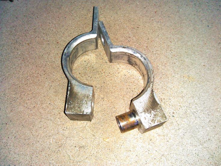
**NOTE** there is a steel roll pin inside the aluminum bracket so be careful cracking it open. 8. Once its open, lube the pin and the hole with anti-seize. 9. I hammered the roll pin all the way to one side(roll pin placed on 2×4)
After doing this the pieces go together easily.
10. Reinstalling is also tricky, place the sliced part of the bushing facing up. (I also put anti-seize on the inside of the bracket to help seat the bushing)
11. Install bracket around rack and bushing you must hold it in place until you get the top bolt in (leave it loose) the fit is extremely tight so once the top bolt was in I used channel locks to squeeze the bottom halfs together. (It’s a process)
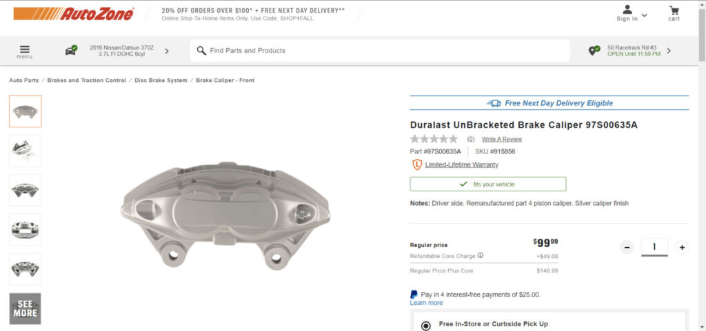
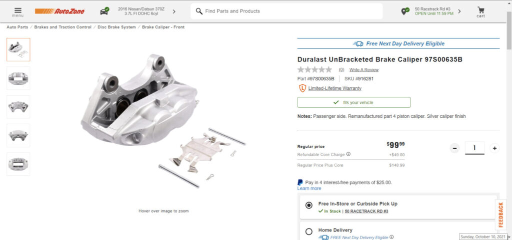
If you are looking to upgrade your Maxima with Akebono’s then check out the deal below at Autozone. You can get both calipers for $200.00 bucks. You can exchange your previous calipers to save the core charge. These calipers work great and are just like the original OEM ones.
Front Driver Side Part Number: 97S00635A Front Passenger Side Part Number: 97S00635AB
Depending on the Maxima year, you will also need the following:
Important Note: These brackets for only for the front calipers. The rear Akebono calipers are plug-n-play but only for the 04+ Maximas/ 05+ SE-R Altimas.
Four M14x45mm long bolts (Note: these bolts will stick out beyond the adapter to mount M14x1.5mm nuts if desired [recommended].)
Four M14x55mm long bolts
Four washers (if nuts are being used with the kit)
A pair of Grade 6 aluminum calipers
Tools you will need:
22MM sized socket or wrench
A fine file or fine burr drill bit (if modification required)
Torque wrench
STEP 1
Due to casting variation of the Akebono calipers, some slight modification may be required to the adapter in order for it to clear the body of the caliper.
Using your 55mm long bolts, thread the adapters to your Akebono caliper until seated. The adapter is mounted to the caliper with the bottom of the “L” shape of the adapter oriented to towards the bleeder while the machined notch sits towards the caliper.
Verify that the notched portion clears the body of the caliper. If it does not, mark the area of contact and remove the appropriate amount of material until cleared. (Take away about 1-2mm of material at a time at approximately a 45-degree angle to match the caliper body angle. Re-mount to verify clearance. Repeat if necessary).
STEP 2
Mount your adapter to your spindle. The adapter sits outside of the spindle mounting holes while the 45mm long bolts mount from the inside of the spindle towards the body of the car. Hand thread one 45mm long bolt by only a couple of rotations. Take your other 45mm bolt and repeat for the other mounting point while extending the adapter away from the spindle. This will allow for extra pitch and play to align your second bolt to the threads of the adapter.
STEP 3
Once both bolts are comfortably thread-started into the adapter, fully thread both bolts through and tighten to OEM specifications.
NOTE: DO NOT FORCE BOLTS ONTO STARTING THREADS OF THE ADAPTER! This may result in damage or cross-threading to the aluminum adapter.
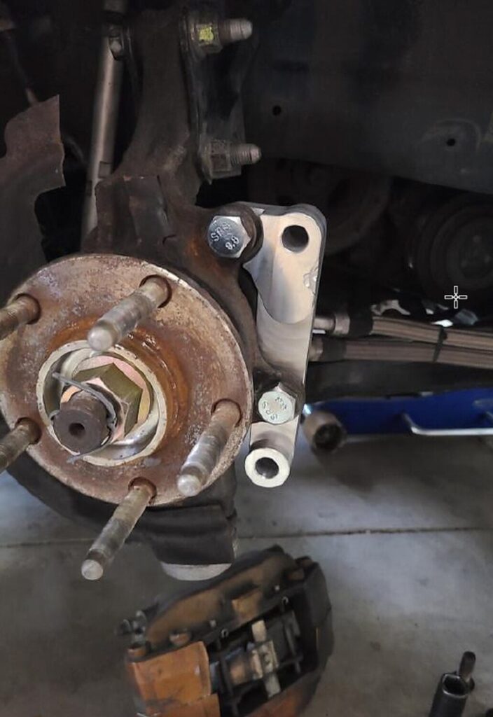
Your bracket will look like this mounted to the vehicle:
STEP 4
Repeat all steps to the opposite side of your car. Mount your Akebono calipers using the supplied 55mm long bolts. Tighten to OEM specifications. NOTE: Part of the dust shield will need to be trimmed in order for the caliper to be mounted. Use metal shears or a cut-off wheel with the appropriate tool to complete this step.
STEP 5
Double-check all fasteners for tightness prior to driving your vehicle. Test drive and enjoy!
*** This kit is to be used for off-road use only. No warranty is implied or expressed. Purchaser assumes all liability. Tighten all fasteners to OEM specifications. ***
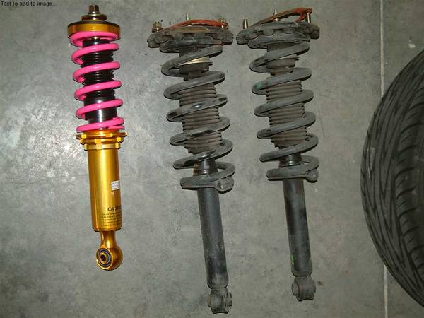
Here is what the rear Coilover that I tested looked like compared to the stock rear suspension. These are still being tested and are not offered yet.
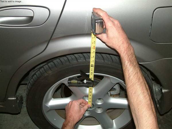
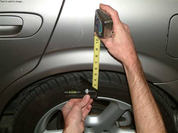
You will first want to measure the car’s wheel gap right now and think of how much u want to lower it by.Be sure to write all your numbers down.
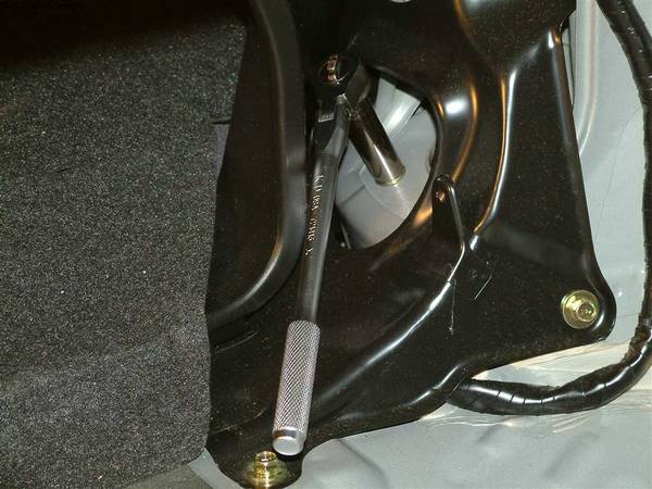
1.) To remove the stock suspension; first, remove the interior sideliner in the trunk.
2.) Jack up the car from the rear and make sure you use jack stands. Then release the jack but barely keep the jack off the rear axle.
3.) Remove the wheels.
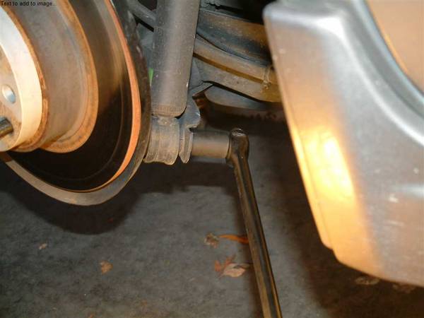
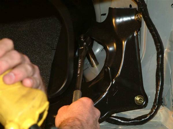
4.) Undo the bolt on the bottom of the stock suspension.
5.) Remove the bolts at the top. There are two of them.Have someone catch the spring and strut when you undo these bolts.
1st Bolt
2nd Bolt
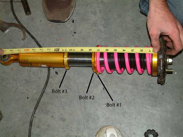
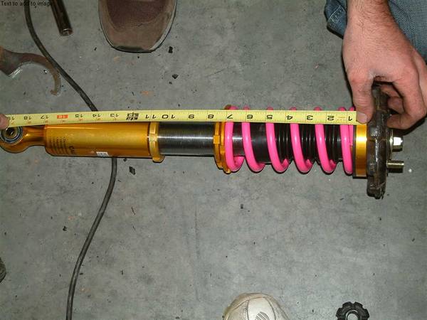
6.) Now measure the total length of the stock strut and spring. A good way to measure is from the bottom of the perch (the big black thing at the top of the stock strut assembly) to the center of the hole for the lower attachment. See how it’s done on this coilover.
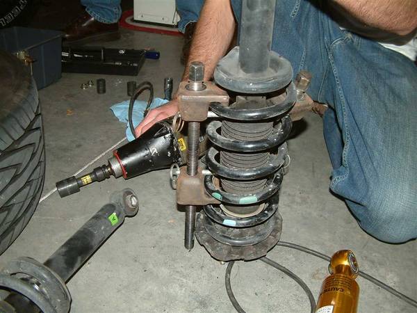
7.) Now disassemble the stock strut and spring. You will need a spring compressor for this job.You may want to hit the bolt at the top of the strut with an impact to loosen it a bit, but don’t remove.
8.) When you have the spring compressed you can remove the bolt at the top of the strut and the top assembly will come off and then the spring.The only thing you want to keep from the stock strut assembly is the big black perch, the bump stop below it and the thick rubber washer above it. This will be used on the coilover.
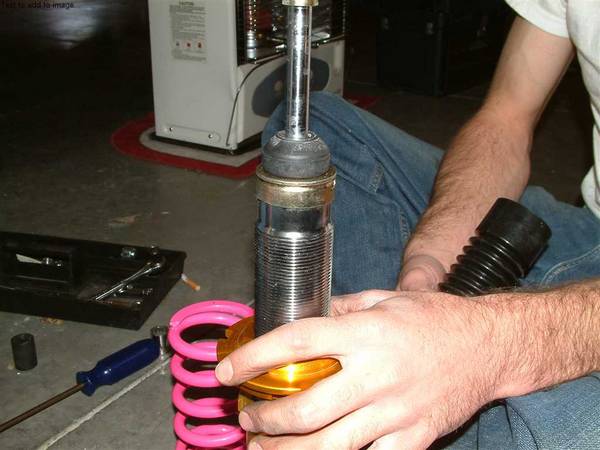
9.)Now to the coilover. The coilover will come all fairly loose. Take all the stuff off like the spring and dust boot ect. The upper metal washer and bolt will be used again as the very top pieces.You will see a bumpstop here:
10.)Now make sure there is a washer inside the black dustboot. Put this over the assembly, then the spring and then the bumpstop from the stock strut assembly on top.
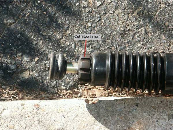
IMPORTANT NOTE: The bumpstop you see in these pictures has not been cut in half. You will need to do this. This bumpstop is made to fit into the perch. If you look the perch underside is designed to the outline of this bumpstop. Look lower for more info.
Below is a picture of the bumpstop cut in half.
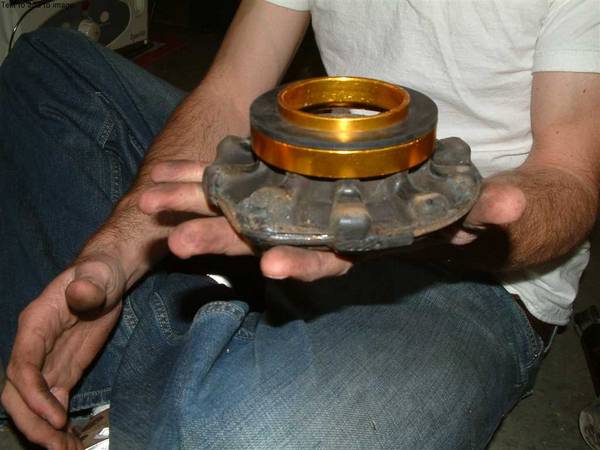
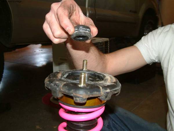
11.) Now there is a gold ring with a rubber gasket on it. This goes on the stock perch like so:
12.) This in turn goes on top of the coilover:
13.) And then install the upper bushing and then metal washer and bolt.
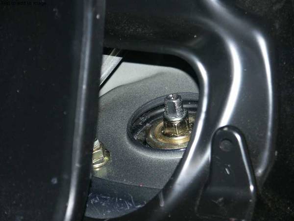
14.)Now if you have an impact, try to impact the top bolt tight. There should be roughly 10 threads sticking out. Look below for a picture of this.Also the bolt is a nylon lock. Mine was tough as heck to tighten. We had to actually cut away some of the nylon away to get the bolt on and then we used locktite.
15.)Ok here is the coilover all put together
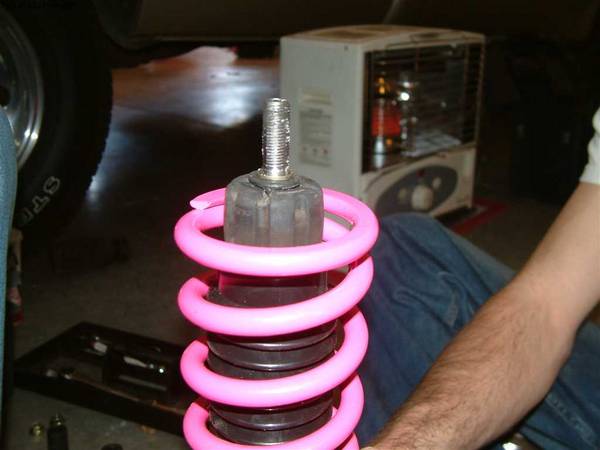
Note how the very top bolt has no threads out. This is because the bumpstop was not cut in half. If you cut the bumpstop in half then you will have 10 threads showing through like so:
(This is just to show how much threads are sticking out. Don’t bolt up just yet. Measurements still need to be done) (Also make sure flat edge is facing this way)
IMPORTANT NOTE ON INSTALLING COILOVER:When you install the coilover, back install it just the opposite of when you removed the stock strut assembly except for two things. First:If you look down the coilover from the top, you will see that the strut sticking out of the bolt is not exactly round. It has a flat part. Make sure that flat part is facing toward the inside of the trunk and not away.Look at the picture above with the note.Second:The lower part of the strut which you bolt to the car is not perfectly flush on both sides. It will stick out a lot on one side.There is only two ways this part can go into the mounting area.THE PART THAT STICKS OUT MUST STICK OUT AWAY FROM THE CAR. (AWAY FROM THE CENTER OF THE CAR) If not this will rub against the metal brackets that the strut goes in and damage the coilover.
16.)(See below for bolt numbering) Now the coilover is assembled the spring tension needs to be set.You will need to tighten the spring until its just snug. I put it under a little tension but not much.This is done by tightening up Bolt #1 until the spring is under a small amount of tension. (Usually until you can not turn the spring in the coilover.)Tighten up Bolt #2 up to Bolt #1. Make sure this is nice and tight.
17a.)Ok now you need to start doing some measurements.I started out by making the length of the coilover the same as my stock strut assembly. Do this for both sides by turning the lower part of the coilover seen below Bolt #3 until length is right.Install the coilover and wheels. Lower the car.I did two measurements. From the fender well to the top of the rim and from the fender well to the center of the rim.
17b.)Now see how much you want more wheel gap you want to take out or add and remember this.Jack the car back up take off each wheel.I was able to make changes by taking apart the lower coilover only and able to leave the top part in place.Turn the lower part of the coilover until you have reached the right measurement. Install the lower part, and tighten up Bolt#3.Make sure both sides are equal. If not just adjust one side to match the other by adjusting the lower part of the coilover only.
Installing the front coilover:When installing the front coilover it’s easy after you have done the front. There is no disassembly or adding to the coilover.Just take out the front stock strut assembly. Be careful with all the lines and cables attached to the front strut assembly. Then measure it in a similar fashion to the rear.On the coilover make sure the spring is barely in tension like in the rear. Turn the lower coilover to match the length of the stock strut. Install the coilover, lower the car, and see how much wheel gap u want to take out or add. Jack the car up and take the coilover off and make the appropriate adjustments to the lower part of the coilover by turning it. When u have desired height, then tighten everything up. Here’s the tricky part. U have to watch out for the lines and cables. This coilover does not have any brackets to hold these. What I did was zip tie them to good structures. But you need someone in the car turning the wheel right and left to make sure it won’t pull these cables and lines.If all is well fasten them down. Drop the car and go get it aligned.You really do not need camber plates. 2002 maxima I know have tons of camber to play with. I dropped my front end 2” and does not need any camber plates.If someone tells you that you need them maybe get second opinion. This is what happened to me. I took it to pep boys and they said I would need camber plates. I took it to a specialty shop in alignment and they got it done is 10 mins.
These brackets will guarantee the proper fitment of Akebono calipers on your Maxima or Altima. Say goodbye to pad overhang and knocking off wheel weights when running your 18s!
The kits will be made out of 6061 high-strength aluminum. I am currently in talks with the machinist to see if I can do a separate run of steel brackets though. I was quoted $45 USD more (subject to change).
The aluminum kits will cost $225 plus shipping and PayPal fees. ($50.00 Deposit Required)
Important Note: These brackets for only for the front calipers. The rear Akebono calipers are plug-n-play but only for the 04+ Maximas/ 05+ SE-R Altimas.
Improvements (Over Previous Brackets):
Mounting holes to the knuckles have been shifted to the correct spots to fix the pad overhang problem.
A notch has been made to clear the curvature of the caliper as it was not allowing it to seat on the bracket properly.
The caliper mounting holes were oversized. This is also corrected.
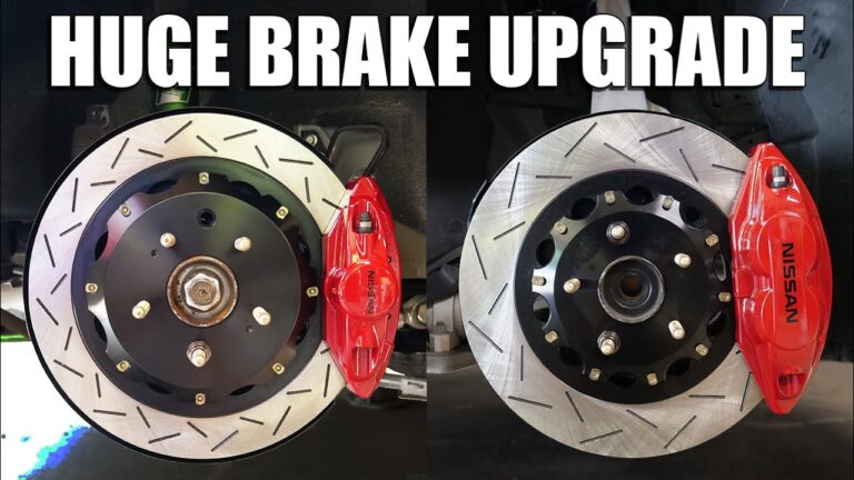
Ok, so since this is something that’s becoming ever more popular, I decided to compile all of the information you need to upgrade the front brakes on your 5th gen to the 6th gen brakes with 12.6″ rotors…
First check your wheel clearance to make sure you have enough room for the brakes to fit. Measure from the center of your wheel to the inside of it, and if you don’t have at LEAST 7 5/8″ these brakes will not fit on your car…they do fit the 5.5 gen 17″ SE wheels like a glove, but they don’t fit with the 5.0 gen SE 17s…
f you do have enough clearance, the next step is to purchase what you need for the upgrade. Here are the things you need to get your hands on:
6th gen calipers (I bought mine from Dave B. for ~$60 each)
6th gen 12.6″ rotors (I bought mine from automax’s GD; brembo blanks for ~$100 shipped)
6th gen front brake pads (Also bought from automax’s GD; PBR metal masters for ~$50 shipped)
6th gen front brake shim kit (got mine from Dave B. I think for under $20)
Brake fluid of your choice
These are DIRECT BOLT-ON for ALL 5th gens (5.0 and 5.5 alike) but you can also opt to get Matt Blehm’s relocation bracket on the 5.0 gen (but not the 5.5 gen) and use your stock calipers.
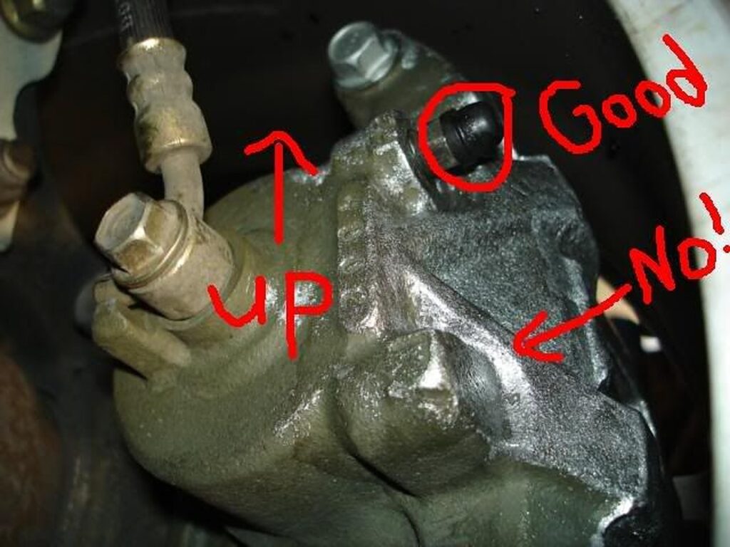
Installation for me would have gone smooth if I had a right and a left caliper, but I accidentally got 2 left ones! DOH! Make sure when installing the calipers that the bleed screw is on TOP. (shown in the picture below.)
For me, the pedal feel was GREATLY improved (although this may be because I was running on my stock brakes at 50k). The pedal feels firm, and even after beating the sh!t out of my car at MSR during Maxus, I didn’t get an ounce of brake fade with my ATE Super Blue Dot 4 fluid.
I bed the brakes in just after installation and so far no abnormal noises or vibrations. There is great feedback from the brakes and they don’t seem to lock up under extreme braking as they did before.
From a performance point of view, I could not tell any difference in acceleration. These rotors did feel really heavy, but IIRC they are only 5 or 6 lbs. heavier than stock, which also felt really heavy, so it would be pretty hard to feel any adverse effects on acceleration.
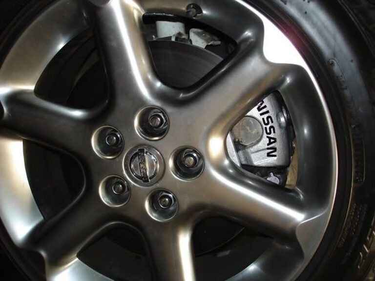
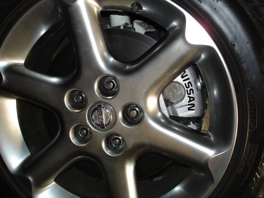
As for the paint on my calipers, I used the G2 silver paint kit. I applied the paint only where you could see the caliper from the outside, and I applied 3 coats with much more paint to spare. The decals are just stick on (I put a couple of coats of clear over it just to make sure they would stay).
Any other useful information is welcome, as I believe this is all I have. Good luck to anyone that attempts it, and in my eyes, it was a very worthwhile mod.




 I did this after installing my headers with the Y-pipe removed.
 8. Once its open, lube the pin and the hole with anti-seize.
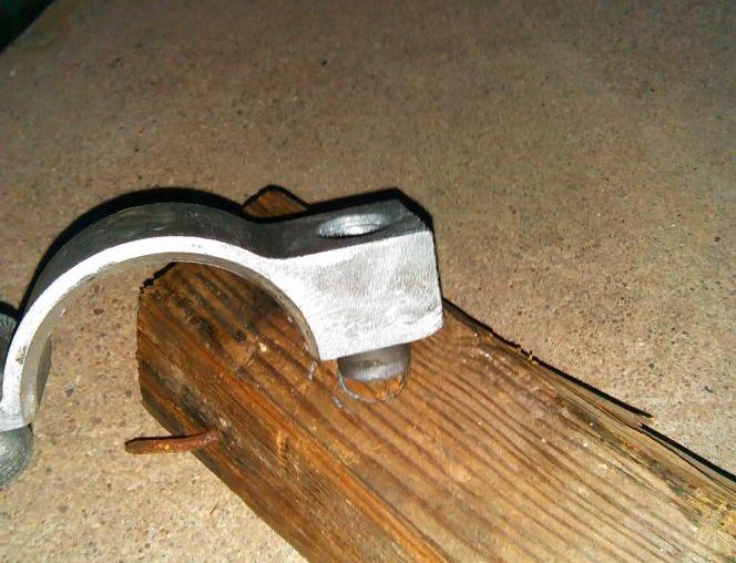 9. I hammered the roll pin all the way to one side(roll pin placed on 2×4)