Tag

Suspension, Handling & Brakes

Browsing

Member Credit: DeusExMaxima

Well, after all the trials and tribulations of installing a part never installed before, I’m finally finished. I took the car for a test drive. Clearly, the car does not lean at all. VERY flat handling, and very nice tracking through a turn. I like the tighter feel in a corner, yet no adverse effects on the straight. That’s the beauty of stiffer sway bars. For $91 and 2-4 hours of time, I say money well spent.

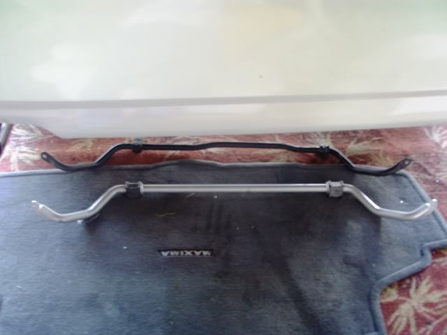
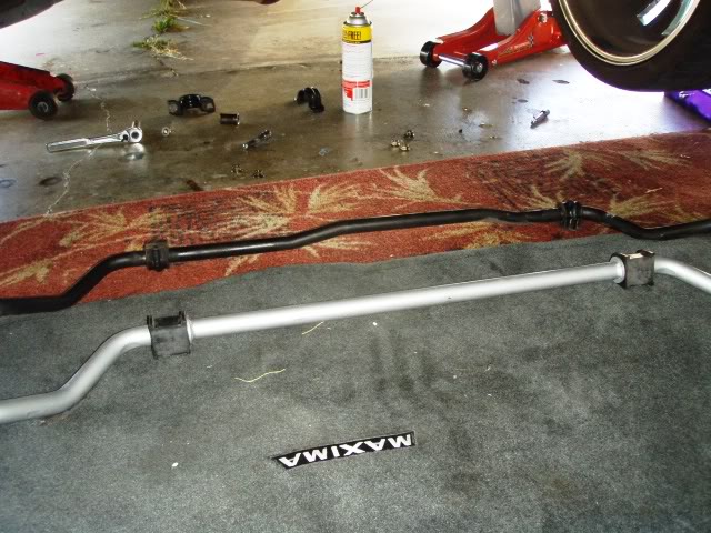
The bar weighs 1 1/2 pounds more than the OEM bar and is 2mm thicker. This may not seem like much, but its significantly stiffer when going through a turn.

Here is the installation instructions:

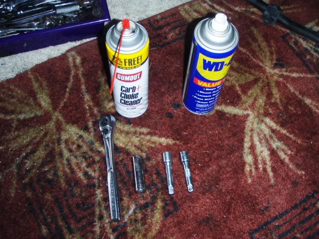
Tools needed – Air tools are very very very helpful. I got some 1/2″ drive hardened metric sockets and an 18″ pipe to fit on my 1/2″ drive ratchet as a breaker bar. I believe the sockets I used were 12mm, 14mm, 17mm and 19mm.

1. Loosen lug nuts and jack car up. IMPORTANT!!!—> Position jack stands behind the brackets that hold subframe. If you put jack stands in front under subframe, you will NOT be able to lower subframe.

2. Remove wheels.

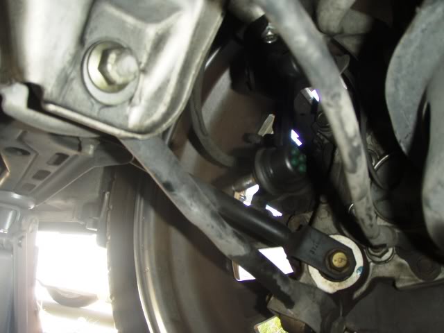
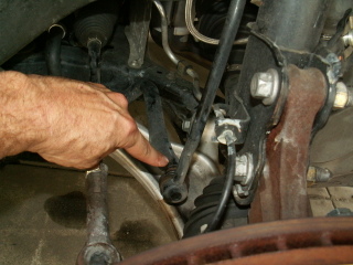
3. Remove sway bar endlink using 17mm wrench.
Click the image to open in full size.
4. Remove y-pipe. This opens up the middle area.

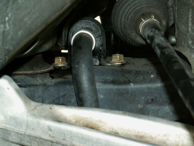
5. Remove the REAR bolt from each sway bar support bushing, but only LOOSEN FRONT bolt of each bushing. Remove these from the wheel well and from underneath in the middle where y-pipe was. Sway bar should be loose now.
Click the image to open in full size.

6. Now the fun part. Use a floor jack and a small piece of wood and support the engine under the oil pan. Just make sure its supported. DO NOT raise the car at all with this jack or you will bend the oil pan.

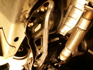
7. Remove the rear sub frame support brackets. The two rear bolts on each bracket are 12mm and the large front one is 19mm.
Click the image to open in full size.

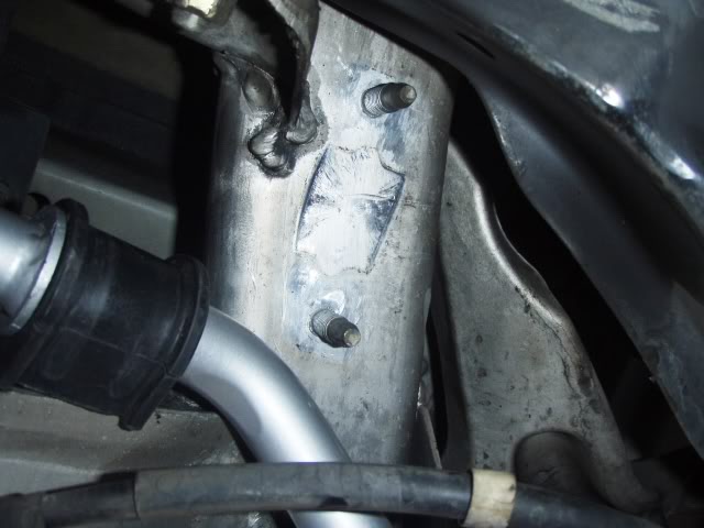
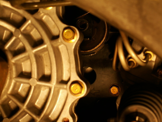
8. Remove the looooong 17mm bolt from the rear motor mount. its located in the center of the subframe and its fairly high up. I used my 18″ pipe on a ratchet and it broke loose easily. Here is a shot of the mount without the bolt. Its in the top center of pic behind the tranny.
Click the image to open in full size.

9. Now you have to pry the subframe down so it drops below the big bolt on each side. I got it down and then put in a small floor jack and pried it until the subframe cleared to two rear bolts hanging down.

10. I removed the sway bar from the side rather than out the back. Either way is fine. Take your time. A helper is good here to help snake that curly bar outta there.

11. I marked the old bar on the top passenger side and then took the new bar and put it next to it and marked it as well. That way, there is no confusion as to which way the bar goes in.

12. Snake the new bar in.

13. Now you have to jack up the subframe. Mine was a little off and I loosened the front subframe bolts and pried it until it lined up. This part is tough. Two people are almost mandatory.

BEFORE YOU GO ON TO THE NEXT STEP . . .MAKE SURE THE STEERING SPLINE DID NOT PULL OUT OF THE RECEPTACLE. IF IT DID AND YOU IGNORE IT YOU WILL DO THIS OVER, LIKE I DID. HERE IS A PAINFUL PICTURE:
Click the image to open in full size.

LOOK UNDER THE DASH AT THE BASE OF THE STEERING COLUMN ON THE FLOOR, AND THE SPLINE SHOULD NOT LOOK LIKE THE PIC. IF IT DOES, GET IT BACK IN THE RECEPTACLE.

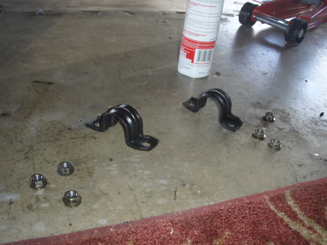
14. Now bolt it all back together. Subframe bolts, sway bar bushings, motor mount bolt (looooong one), y-pipe, and then end links. Sway bar support bushings are marked “L” and “R”. Left is drivers side and R is passenger side. The slit in the bushing is at the front. Make sure you lube the bushing inside and out. I used anti seize compound.

15. Put wheels back on, let it down, and fire it up.

16. FOR SAFETY SAKE . … take it easy for a bit to make sure nothing is loose. Then slowly take corners. See how flat it is through the turn??? Tracking is great.

Loading

Member Credit: mightymax

Click the image to open in full size.

Next, take off the plastic covers a pick or small screwdriver will work

Click the image to open in full size.

Remove 6 14mm nuts from towers

Click the image to open in full size.

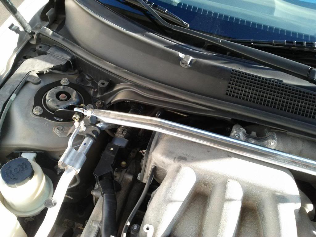
You need to relocate the service port for the A/C, very simple just pull it up out of the white clip and move the clip to the opposite side of the port. This will give you more than enough clearance to tighten the 19mm nut, and save your tech some hassle when it comes time for A/C service.

Click the image to open in full size.

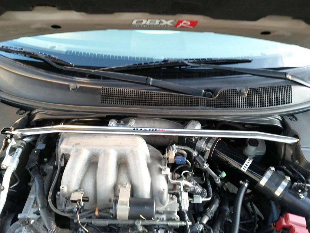
Install your FSTB, might take some finnagling to get the bolts to line up right, but it should fit, retorque the nuts and tighten the allen/14mm brass nut on each side and the 19mm adjustment nut

Click the image to open in full size.

This was the trickiest part. Your OEM plastics will not fit over the FSTB, you can keep them off or do as I did and trim to fit. I just eyeballed it and took the dremel to it and sanded off the burrs. Reinstall your plastics and your good to go!!!

Click the image to open in full size.

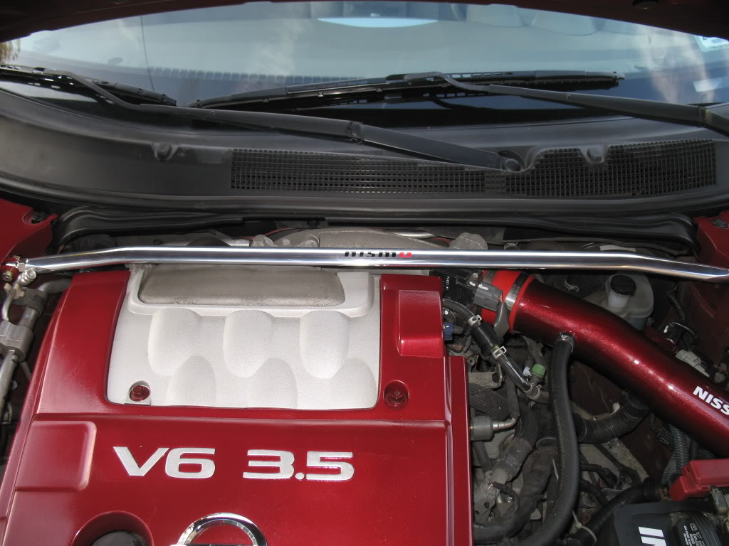
Pic with OEM cover installed

Click the image to open in full size.

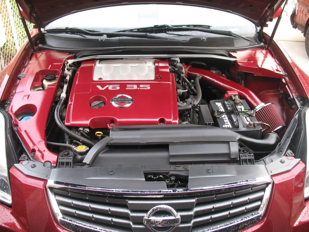
Still have clearance after spacer install, and I haven’t seen any sign of rubbing on hood %image_alt%

Click the image to open in full size.

Additional Pics by Member Scui

Click the image to open in full size.

Loading

Member Credit: jgadlage

I wanted to give a walk-through of how to install the 2 brace setup as it is a little different:

I would recommend that you use the following when doing this install:

• Power drill with a 21/52 bit (it is 1 size bigger than a 5/16 bit- you could use a 5/16 and then just make it larger)
• 5/16 socket wrench
• Level
• Get a 1 inch 5/16 bolt (as KCMAXX currently has ¾ inch 5/16 bolts and I’ve told KCMAXX about this and hopefully he’ll change it with the future2 brace kits). This gives a little more thread for the nut to grab hold of.

Installation
Total install time took about 4 hours, but it really should take no more than an actual hour of real labor. I ate away time doing the following:

• Trying to find a good mounting position for the lower bar
• Drilling out one side to mount the bar
• Finding that the included bolts aren’t long enough
• Going to get longer bolts
• Mounting one side
• Drilling out the mounting location for the other side
• Finding out that mounting location isn’t level
• Guestimating another location based on the previous and drilling it.
• Checking the level and drilling through the brace
• Cutting the carpet where the bars are in order to pull it back into place

Suggestions: I would suggest installing the bars in the following way:

Top brace
Install with the bar from the interior of the car with the bolts on the interior side and the nut on the trunk side

Bottom Brace
Install the bar in the interior of the trunk with the bolts on the interior side and the nuts on the trunk side. This way you will be going through the same metal mounting plate as the top brace as well as the silver brace below it to increase the rigidity of the mounting holes you will have to drill out. Try to drill out a hole for the brace at 5 1/4 inches up from the folded down seatback on the drivers side 3 inches over from the seat, and 5 1/4 inches up and 2 1/4 inches over on the passangers side. This should get you in the area that I drilled out my holes, but you might need to see what works best for you.

Hopefully these pictures will help you out in mounting your rear lower strut brace. Let me know if you have any questions and I’ll get back to you as soon as possible.

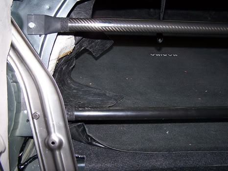
Shows the where I decided to drill on the metal brace that the the upper strut brace mounts to as well as the silver brace behind it.

Click the image to open in full size.

Interior view (passanger side) of lower brace mounting pont

Click the image to open in full size.

Interior view (driver side) of lower brace mounting point – I drilled once, missed the mark, drilled again got in the right ballpark, but the level was off, drilled a 3rd time and it was better.

Click the image to open in full size.

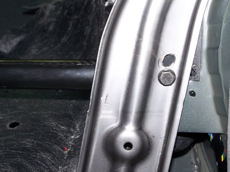
Interior view (driver side) of upper and lower brace mounting points. If you look to the right of where the brace is connected you will see a hole. That is where the bar would have connected with the stock mounting point, but there was no way that the bolt would fit and be able to be snugged down with the silver brace in the way. I corrected this by drilling in the current location through the silver brace, metal, and support bar. Everything seems solid now.

Click the image to open in full size.

Both braces installed with carpet peeled back

Click the image to open in full size.

Both braces installed with carpet put back in place

Click the image to open in full size.

Here are my impressions on how the car handled before and after the install of these braces:

Before
The car has more of a luxury car feel in that the suspension is soft and feels a bit floaty over bumps in higher speed sweeping corners. It has body roll (both left/right and up down). It feels kind of like a boat in that it’s comfy, but it doesn’t inspire confidence when you first go into a uneven fast sweeping corner and find out what the car does (bobbing and rolling).

After
With 1 bar the car does feel more responsive in that the chassis feels more rigid and connected. The front still seems to bob and roll when tossing it around a corner (as the front has yet to receive a FSTB), but the car seems more planted and stable. With the 2nd bar added in, the car feels like a sport/luxury car (it has crisper and more connected handling, but it isn’t harsh). The front still bobs and rolls, but the rear is more stable and planted with the bobbing now gone. A high speed sweeping corner with a bump that would once make me anxious now doesn’t as the rear of the car doesn’t get unsettled. If you are going to put in a rear lower brace, I would recommend that you take your time and plan out what you are doing as there isn’t a lot of room for mistakes.

Afterthoughts
This is a good upgrade that is well worth the money. It isn’t hard if you are doing either a single bar or a double bar. The single brace was a snap to install, the lower brace was a little more complicated but by no means difficult. I agree with Chernmax in that this is a 1 wrench job that anyone can perform, just take your time and take it one step at a time.

I also want to add a side bar that with the FSTB installed and Rear Sway Bar the car now feels more stable during the long sweeping corners. If I am going around a 180 degree sweeping onramp (I take this onramp everyday so I am used to it and have tested my car many times on it) with a posted 40MPH speed limit I can do the following:
* I can make the corner at 60 with the car holding stable (tires might be squeeling, but the car sticks and is controllable). I could go faster, but I would have to give it all its got and I don’t feel the need to go any faster.
* If I wanted to I can lift off of the gas during this corner at 50MPH and the car might start to kick out the rear end ever so slightly, but the braces bring it right back into line and keep it controllable. If I did this before without the RSB and the FSTB, the rear end would start to come around and regaining control would be a whole lot more difficult.

Morale of the story – don’t let out of the gas during a sweeping corner or brace your car to ensure better handling if you have to so that it keeps in line. At least now I know how my car will react if it does get upset during a corner (either intentional or in a case of emergency) and I can respond accordingly. I am not saying to go blazing into a corner at wreckless speeds, but if you can find a deserted place where you can test your car do it in increasing increments so you can find some limits of your car and know how it will react with your current setup. Better to know what your car will do when the need arises than hope it will react the way you think when the time comes.

Loading

Member Credit: DEADBOLT

Tools Needed: (NOTE: Socket is size 14 & make sure it’s a long socket, not short)

Click the image to open in full size.

1) Jack up the car from BOTH sides.

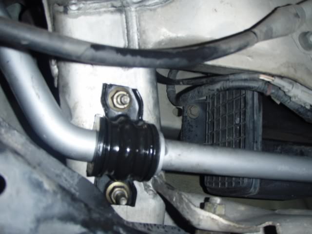
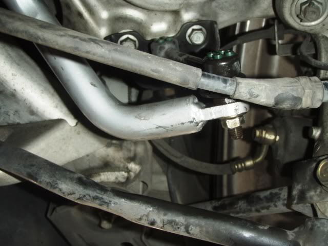
2) Unbolt the outer part of the sway bar first, since the sway bar is stable. There’s 1 bolt on each side

Click the image to open in full size.

Click the image to open in full size.

3) Unbolt the middle section

Click the image to open in full size.

Click the image to open in full size.

Now you should have 3 bolts total from each side and the middle section brackets

Click the image to open in full size.

4) Wiggle the old sway bar out and be careful. Take your time and try twisting the bar to avoid pulling any lines with you. NOTE: Notice the way the sway bar is facing before you put it in.

Click the image to open in full size.

Click the image to open in full size.

5) After you put in the NEW sway bar, connect all bolts in place, but DO NOT tighten anything yet. NOTE: Do the middle section first to hold up the bar because it’s heavier than stock.

Click the image to open in full size.

Click the image to open in full size.

Click the image to open in full size.

Click the image to open in full size.

6) Once every bolt is in place, tighten the outside bolts then do the middle section. And now you’re done.

Enjoy the better handling.

Loading

Member Credit: officerfrasher

Items needed:
350Z/G35 Rear Camber Arms (I bought the Ichiba ones. There are cheaper ones, but they don’t look as strong. Here’s a link for the Ichiba ones on eBay
WD-40, Liquid Wrench, etc.
17mm socket and/or wrench (my impact gun made it real easy, but it can be done without it)
19mm socket and/or wrench
Jack and jack stand

1. Jack up the car and place a jack stand under it.

Click the image to open in full size.

2. Soak the nuts & bolts with WD-40 and let them sit for 10-15 minutes.

Click the image to open in full size.

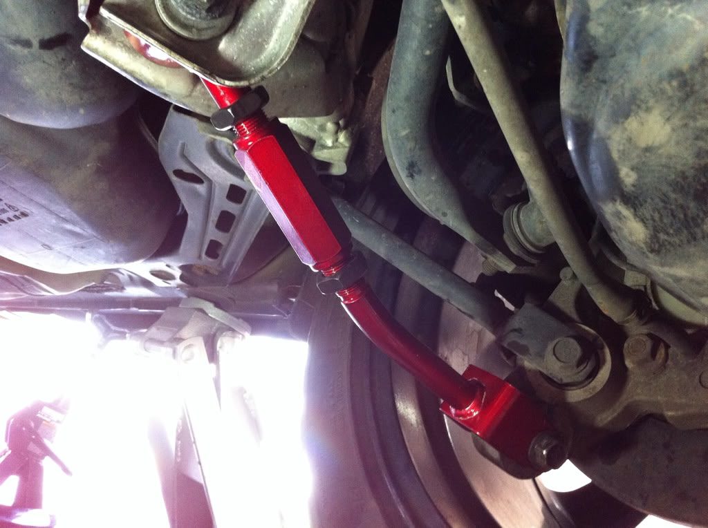
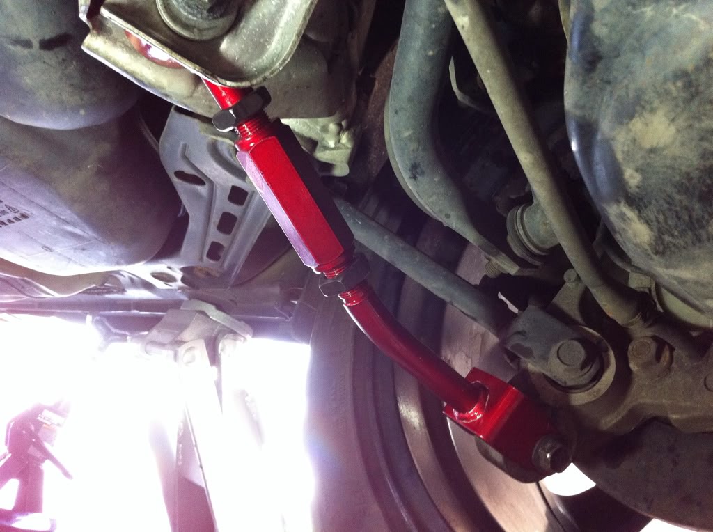
3. Remove the nuts, bolts and OEM arms. The lower nut and bolt are both 17mm. The upper bolt head is 19mm and the nut is 17mm.

4. Install the new camber arms.

Click the image to open in full size.

Click the image to open in full size.

5. Remove jack stand and let car down.

6. Take pics and post them or BE BANNED!

7. Most importantly, GO GET AN ALIGNMENT IMMEDIATELY!

No surprises really and not much to it, just get in there and get it done!

Loading

Member Credit: Scrambler68

Note: Dealing with suspension components are very dangerous, please use cautious when handling a loaded spring as harm may occur.

1. Jack up the vehicle and support with jack stands.

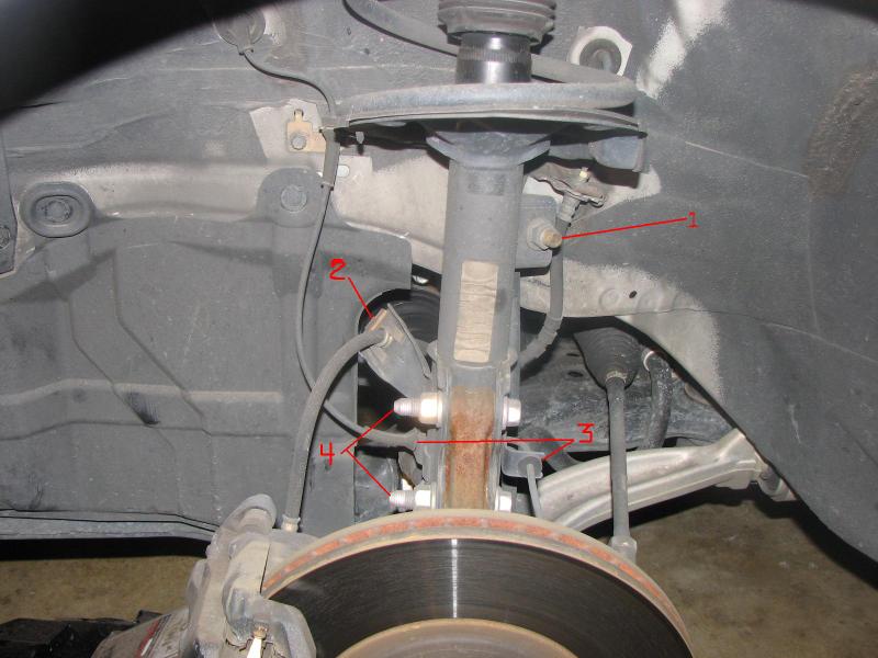
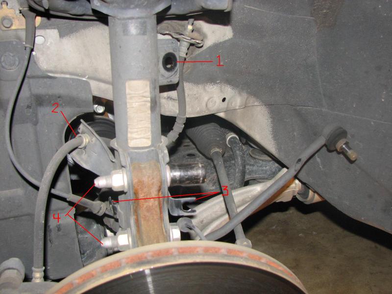
2. Remove the front wheels and you will see this:

Click the image to open in full size.

3. Remove the sway bar end link from the strut (1)

4. Remove the brake line clip (2)

5. Remove the ABS line from the strut (3)

6. Remove the two bolts holding the strut to the knuckle (4)

Click the image to open in full size.

7. Lift the hood and remove the trim above the top of the strut tower.

8. I had to remove the nut from the strut tower bar (1) to access the nut on the strut.

9. Remove the 3 nuts that hold the strut in place (2) and the strut will drop out of the vehicle.

Click the image to open in full size.

10. Use a set of strut spring compressors to pull the spring down (1).

11. Remove the nut from the top of the strut and remove the top plate (2).

Click the image to open in full size.

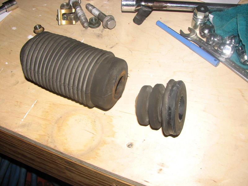
12. Remove the dust boot and cut off the stock bump stop.

Click the image to open in full size.

13. Slide the new bump stop onto the strut shaft then slide the dust boot over that.

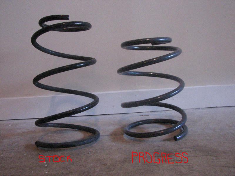
14. Put the Progress spring on the strut and reverse the removal process to install.

Difference between stock and Progress front springs:

Click the image to open in full size.

For the rear springs:

1. Jack up the rear of the vehicle and support with jack stands.

2. Remove the rear wheels.

3. Remove the bolt that holds the lower control arm to the spindle.

Click the image to open in full size.

4. Once the bolt is removed, lower the control arm with a jack. You will have to push it down by hand to remove the rear spring.

Click the image to open in full size.

5. Install the Progress spring using the stock rubber isolator.

6. Jack the control arm up and replace the bolt.
7. Reinstall the rear wheels.

8. Go get an alignment

Loading