Tag

Interior, Exterior & Lighting

Browsing

Credit: DennisMik

I would like to start by thanking JNCoRacer for his motivational pep talk. He was smart enough to know that I could do it, even though I didn’t think I could. Thanks man.

You will need various standard tools: screwdrivers (Phillips for screws & flat for prying), wire cutters and a ratchet, extensions (I found that my 24 inch was very useful), a U-joint, and a 10 & 12mm socket. I strongly recommend a 6 point socket for the 12mm.

You will need one special tool, a T50 Torx, 6 point security wrench. I didn’t have a security Torx but got lucky and was able to modify my standard T50.

Cliff notes version –
1 – Remove the glove box.
2 – Remove the radio/heater control cluster.
3 – Remove the speedometer cluster.
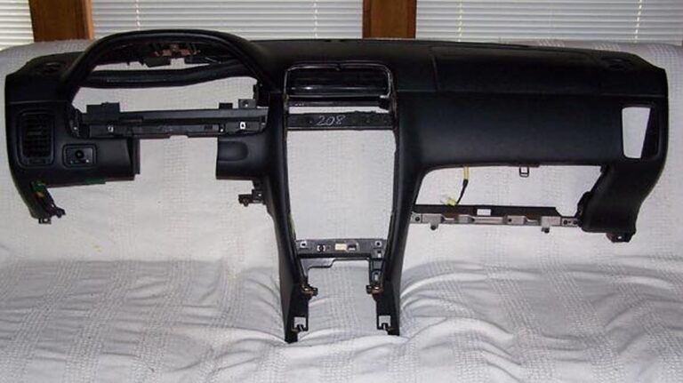
4 – Remove the dash.

Easy smeezy, right?

Let’s get started and find out.

Move the driver’s & passenger’s seats forward and remove the 2 screws that hold down the rear of the center console.

Move the driver’s & passenger’s seats all the way back.

Disconnect the battery. You will be messing with the passenger airbag and it is recommended to wait a half hour after disconnecting the battery.

Remove the glove box (6 Phillips head screws) and disconnect the 2 wires. You will also have to cut the zip tie that holds the wire harness to the glove box.

While you’re down here, remove the kick panel in the foot well. There is a plastic nut on the top front corner that you can most likely remove by hand. Then there is a snap along the top edge just before the panel curves to meet the door. Pull the panel towards the driver’s side to unsnap it.

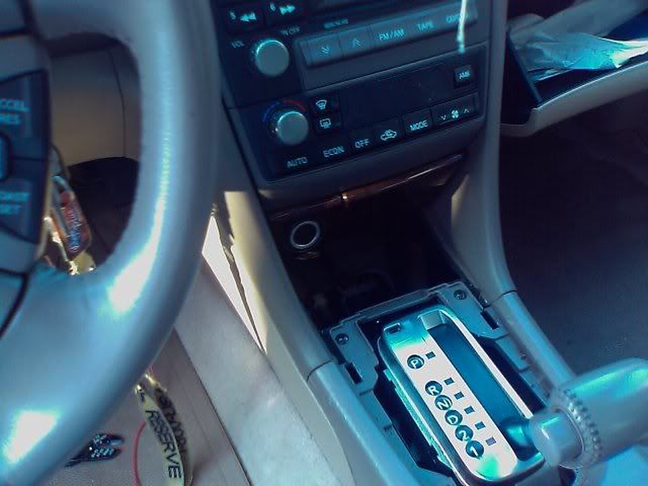
Remove the radio and heater controls. Start by removing the trim plate around the transmission shift lever. If you have an auto trans, you need to move the shift lever out of park. I’m guessing that you’ll need to do the same with a standard trans. Pry up the 2 rear corners of the trim plate to pop the snaps free. Actually, pry on the sides by the corners, not the bottom edge. Lift up by hand to pop the forward snaps that are near the curve. When free, disconnect the wire for the cigarette lighter.

Remove the ash tray. Remove one screw at the top left corner. On the right side there are 2 snaps, one top and one bottom. Pry the ash tray straight back towards the rear. Did I mention that a 1 inch putty knife works better than a screwdriver for this? Disconnect the wire to the ash tray.

Now finish removing the center console. In the opening created by removing the ash tray, there are 2 screws in the corners where the center console meets the dash. Remove those screws, pull the parking brake handle up as far as you can, unsnap the boot around the parking brake handle and remove the center console by lifting up.

Remove the dash center vents. Pry up on the lower corners, the sides, not the bottom edge and pop the snaps free. There are 4 snaps across the top edge. Using moderate level swear words, free the top edge. While it is difficult to do, the vents need to come almost straight back with a little downward motion, not tilted up from the bottom. Once you have the vents free, disconnect the wires for the hazard flasher, clock and the rear window defroster switches.

Now you can remove the radio and heater controls. This is one unit held in by 4 screws, one in each corner, 2 screws down where the ashtray was and 2 on top above the heater controls. Have your transmission shift lever towards the rear of the car and lift out the radio/heater controls. Disconnect the wires from the radio and heater controls.

Remove the speedometer cluster. Since the goal is to remove the dash, this procedure will do things not needed if all you wanted to do is remove the speedometer cluster.

Start by dropping the steering column. Remove the lower dash trim panel that runs underneath the steering column. Remove the 2 screws in the bottom edge at the corners. There are 2 snaps on top edge, again at the corners. Pry the snaps free. *** Caution *** The chime that sounds when you open the door when you have the keys in the ignition is attached to the backside of this panel by the fuse panel. Disconnect this wire.

While you’re down here, remove the kick panel in the foot well, just like on the passenger side. Remove the metal plate that runs underneath the steering column. There is a 10mm bolt on each end. The plate will stay in place after you remove the bolts. Slide the plate towards you about a quarter inch and it’s off.

Now you can drop the steering column. Two 12mm nuts. Mine had Locktite on them and my 12 point socket was starting to strip the one nut, so I changed to a 6 point socket. The steering column is kind of heavy, so you are forewarned. I was concerned about the steering column hanging by itself, so I found a 10 inch length of 2 inch PVC pipe that I rested the steering wheel on.

Now for the speedometer cluster. There is a finishing bezel around the cluster that also has the cruise control on/off switch, the security led and the dash light dimmer switch. You have to disconnect the wires from these switches. You have 2 choices – before you remove the bezel or after. If you choose before, then you have to pry the switches out of their holes and then disconnect the wires. I chose the other option, after I had the bezel loose. This way I didn’t have to pop the switches out.

Start removing the bezel by removing 2 screws in the top curve of the bezel. Then there are 4 snaps along the bottom edge. Pry/pull them free. If you hadn’t done so earlier, disconnect the wires from the switches.

Finally, the speedometer cluster itself. 3 screws, 1 at the top and 2 along the bottom. There are 3 connectors on the back of the speedometer cluster that need to be disconnected. I would suggest you get something soft to lay the cluster face down on while you disconnect the wires so you don’t scratch the face plastic. It costs about $35. You will also have to cut a zip tie that holds the wire harness onto the back of the cluster.

Now disconnect the wires from the side view mirror switch. Either pop the switch out or reach in from behind the dash.

The final phase, remove the dash. There are 5 10mm nuts, 2 Torx head security bolts and a pair of screws to go.

Remove the trim pieces from the windshield pillars by grabbing the trim at the top edge and pulling the snap free. Then lift it off.

Pry off the defroster vent grill plates. There are 4 snaps spaced along the back edge. Pry the back edge of the grill up.

When the grill is removed, you can see a 10mm bolt at the end closest to the outside of the car. Remove this bolt. This is where my 24 inch extension was useful.

In the bottom left and right corners of the dash is a 10mm nut that was revealed when you removed the kick panels. Remove these 2 nuts.

In the opening where the speedometer is a 10mm nut.

In the opening where the radio was there is a screw.

In the opening where the glove box was is a screw.

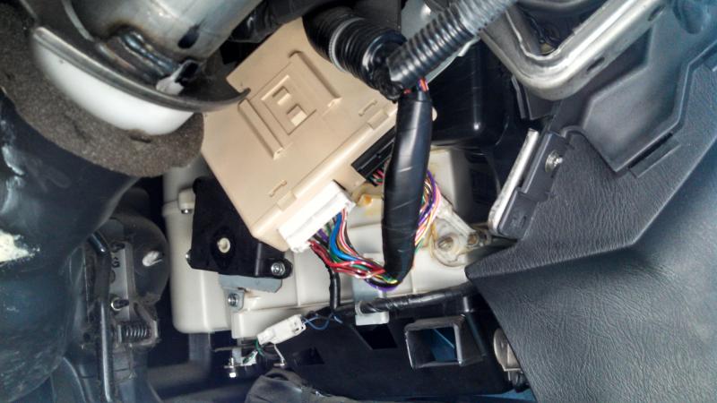
OK, last 2 fasteners and one wire harness connector. Looking in the glove box opening at the top, you will see a yellow wire harness connector. This is for the passenger air bag. It looks like you could pull either end out, but you have to pull the right side out to disconnect it.

Now for the Torx bolts. Look up through the glove box opening and you will see 6 Torx head bolts. You only need to remove the 2 that are by themselves, not the pairs.

Once you have these 2 Torx bolts out, the dash is free and ready for removal. I did it by my self, but if you can get a helper, it is no doubt a lot easier. You have to pivot out the bottom edge a little bit and then pull back and up. There are guide pins built into the top front edge of the dash that require you to pull the entire dash back evenly. Because of the airbag, the right side has probably 75% of the weight.

For what ever it’s worth (in the category of useless trivia), I weighed the dash on my bathroom scale. It was 25.5 pounds. Most of that is the airbag.

Loading

Member Credit: tjmoney87

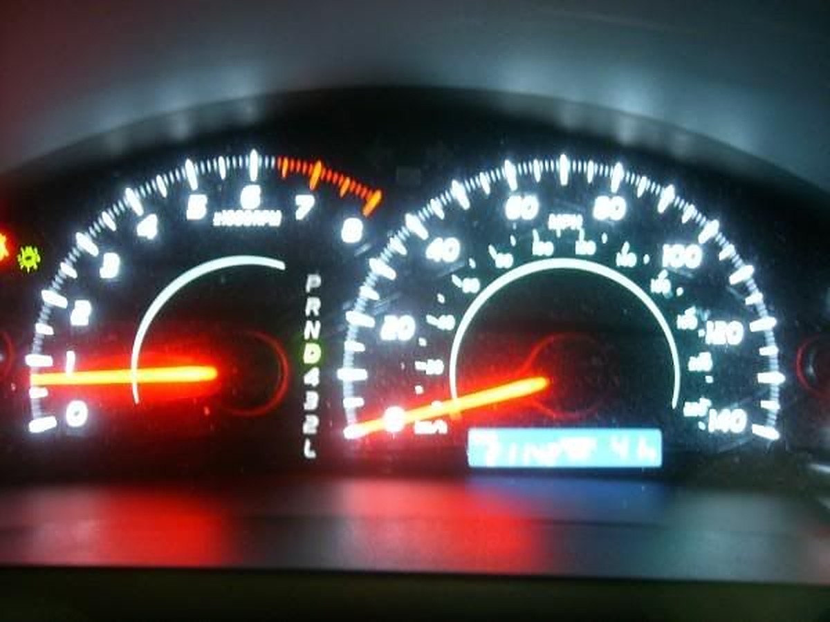
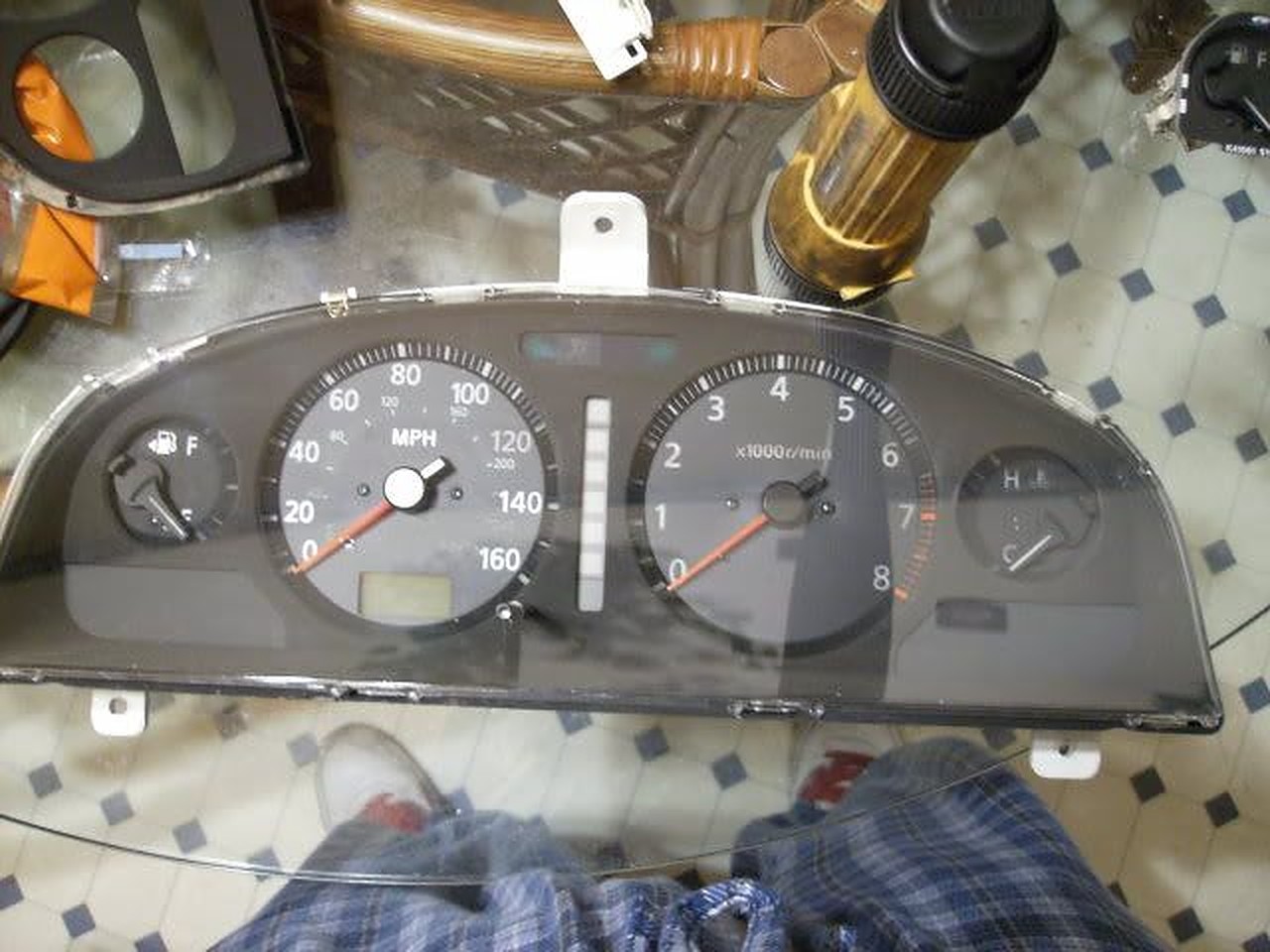
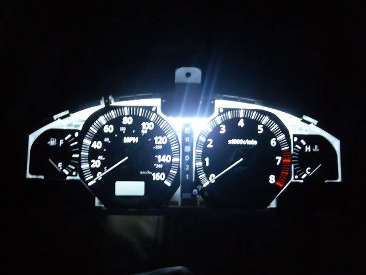
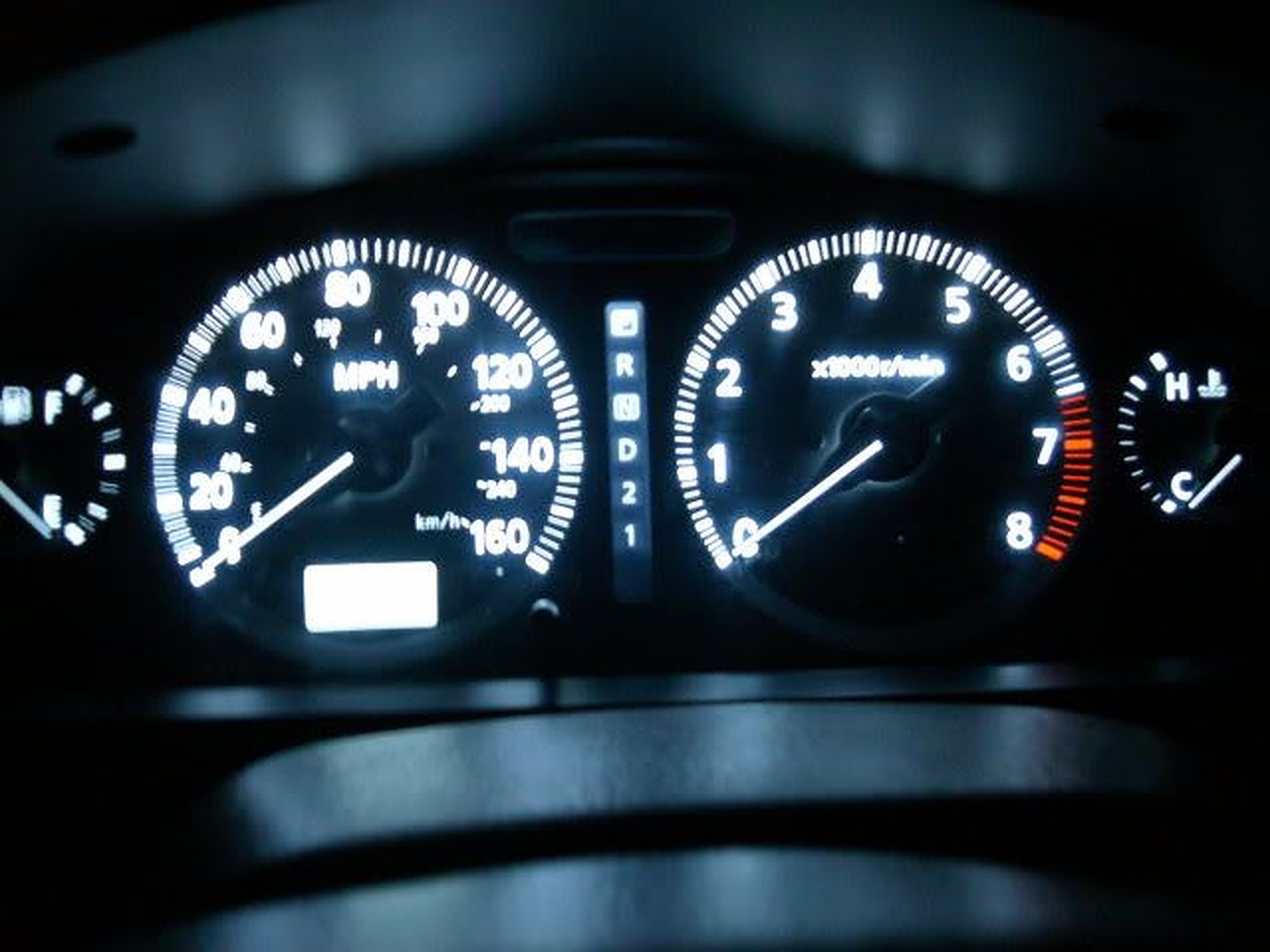
Overall, this is an easy mod if you are careful, but if not, things can get ugly VERY quickly! I would recommend getting a second cluster just to practice…that’s what I did, making sure I was careful enough and to make sure the strip fits. I like it because the cluster lights in ACC mode, but that’s a personal preference (also because the cigarette lighter powers in ACC mode). Also at night, they are BRIGHT (but not bright enough to blind), and do not dim, unless you get a standalone rheostat, I may get one later…I wish I would have got an orange or red one, it would have really nice, but I can always change it out LOL… Also, I would recommend the Maxima’s clear outer cluster cover, http://www.courtesyparts.com/24813-c…3-p-47148.html, our tinted cluster cover would dull things a bit…

Difficulty: 7/10

Pros: LED strip brighter than EL tube, no more dim cluster on one side !
Lights in ACC mode (personal preference). Several colors you could use (again personal preference).

Cons: If you are not careful, things can get ugly quickly! You will have to buy the Maxima’s cluster to enjoy the LED cluster.

Comparisons

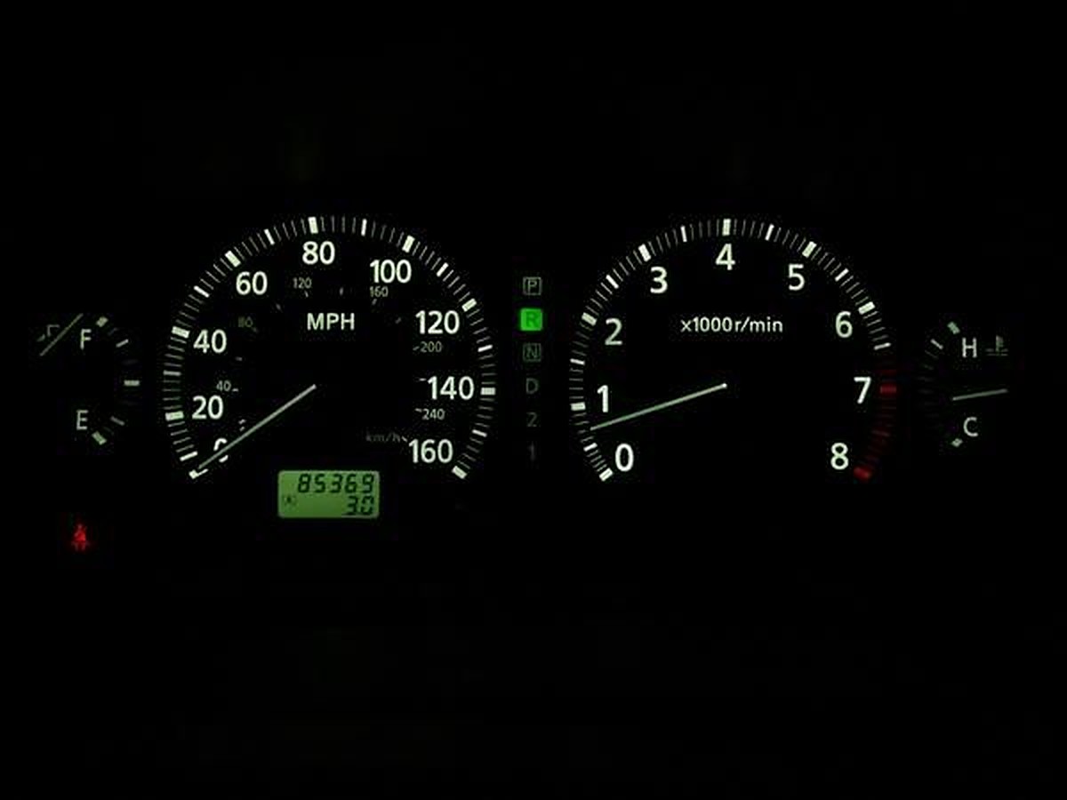
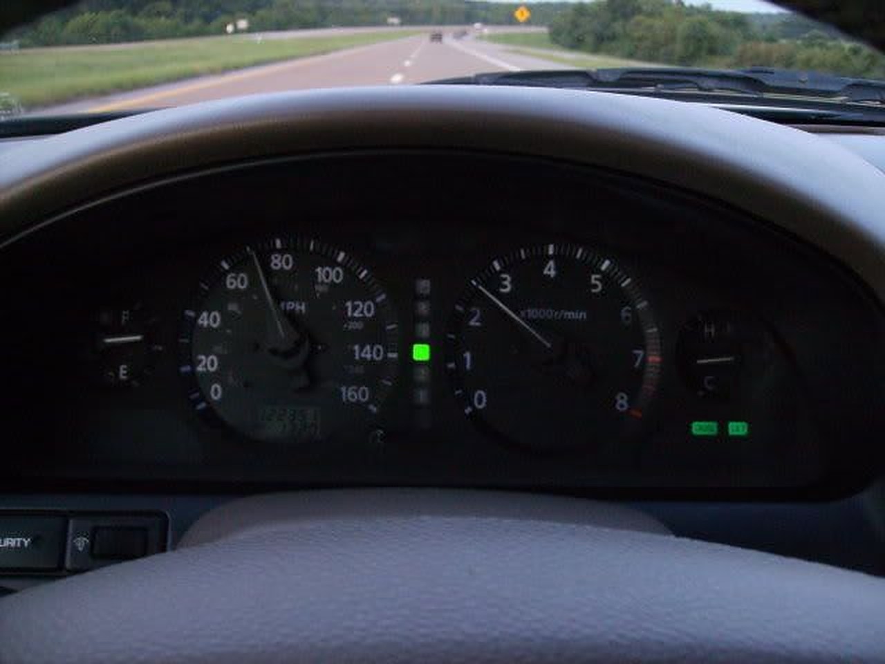
Stock

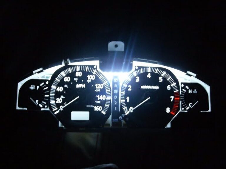
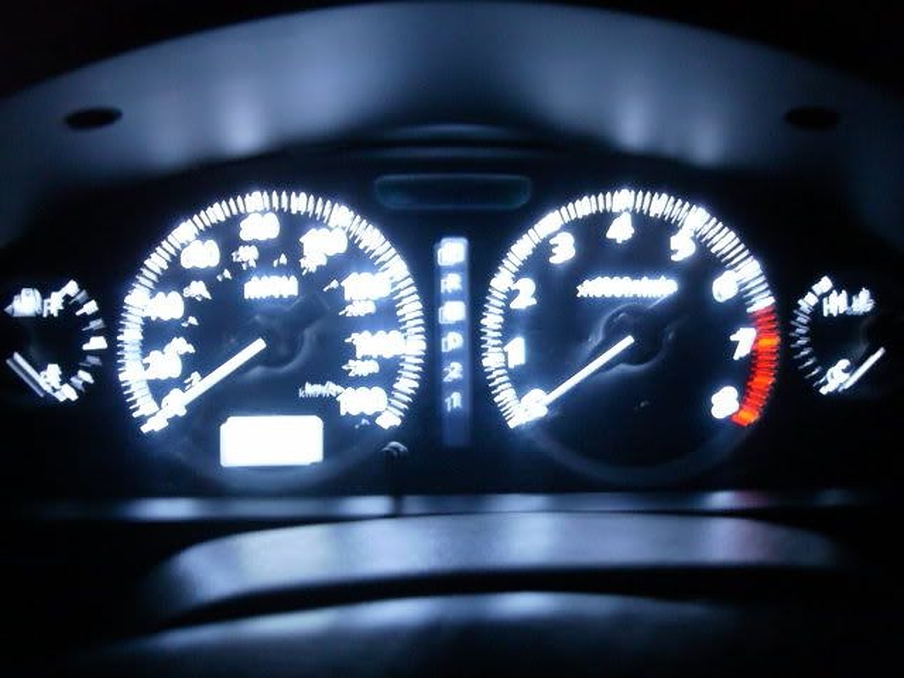
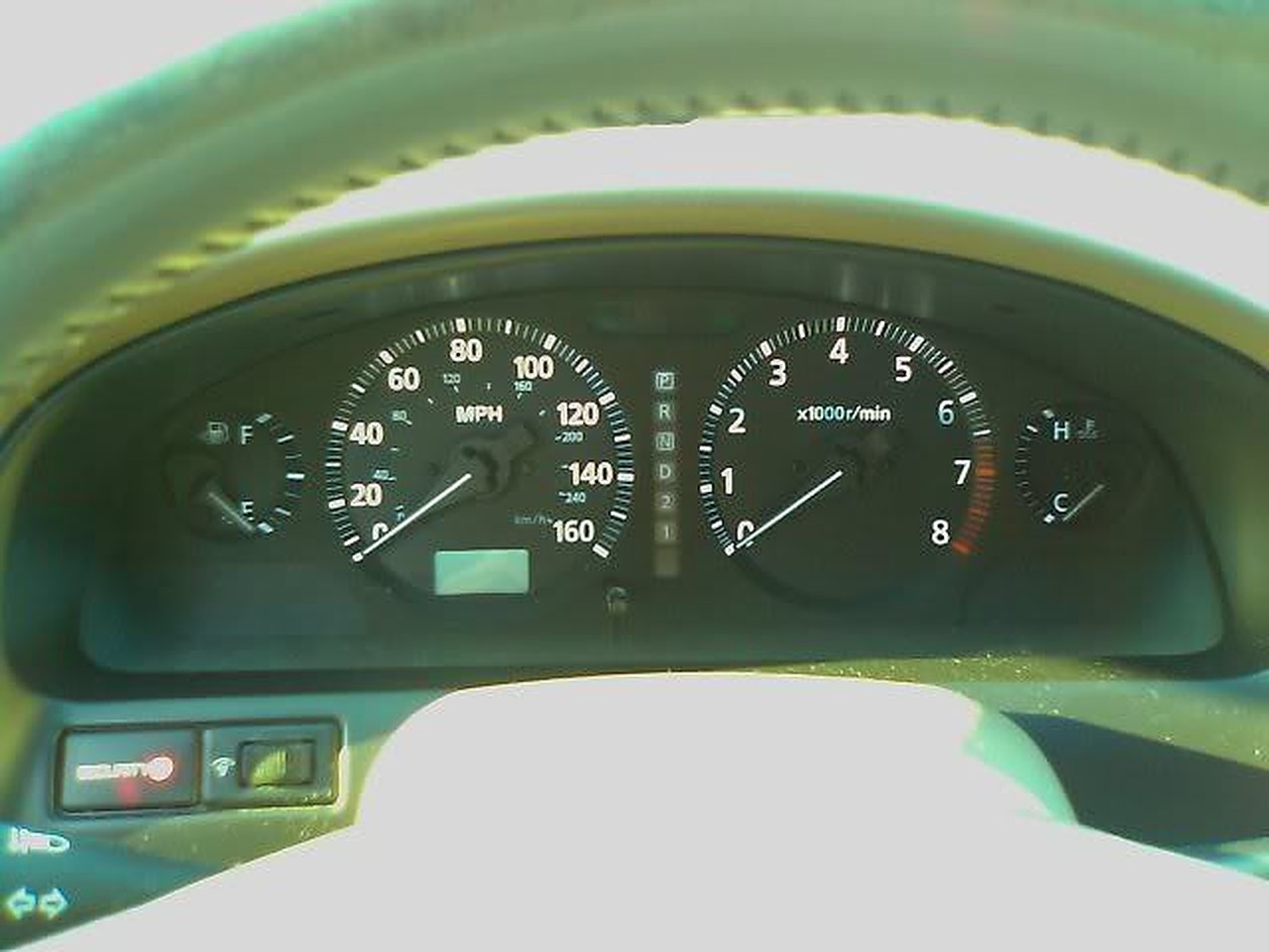
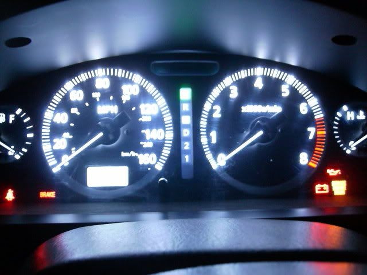
After LED strip swap

My mom’s ’09 Altima

An ’09 Camry

Write-up Instructions

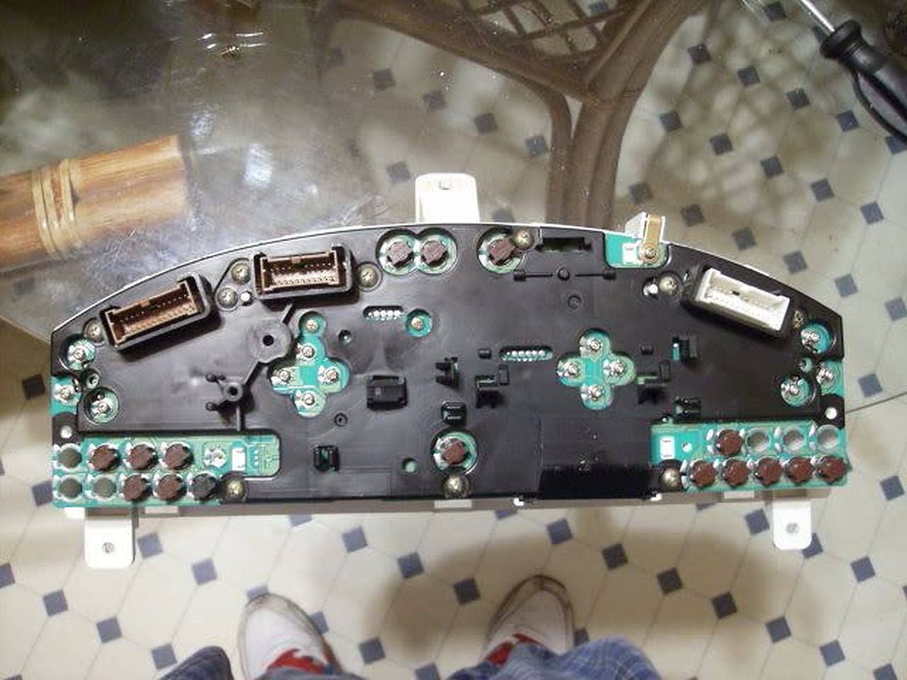
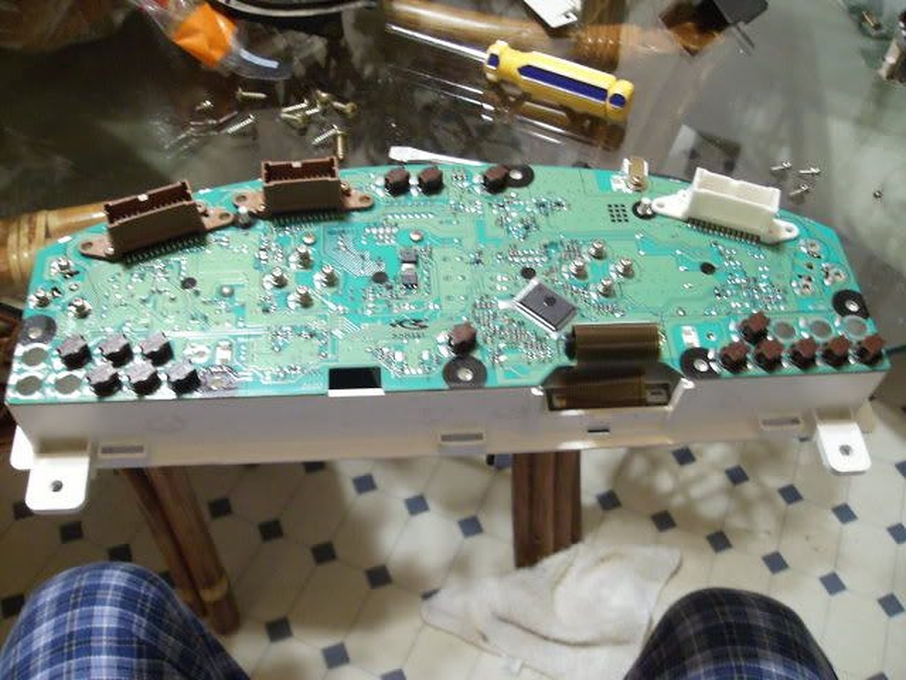
1. Take the cluster out of the car (this should be self-explanatory).

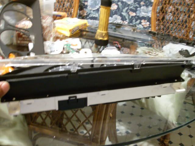
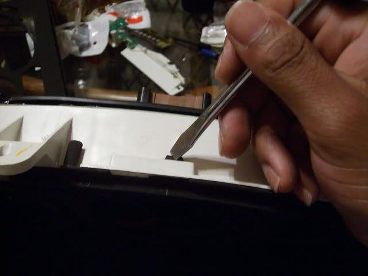
2. Take the outer cover out of the cluster (be careful, it is easy to break!)

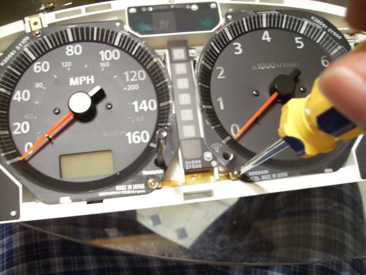
3. Remove inner cover (black part) out of the cluster.

4. By now you should see all of the screws to remove the gauges.

5. Removed the circuit board cover to make everything easier…

6. Here you can keep the gauges together as one after pulling up, or you can have them separated (which I did) by removing screw on the bottom of the speedo and tach.

7. Before removing speedo head, remove odometer head. PLEASE be careful, that odo head is on their pretty tough it would be easier to break the tab rather than the odo head!

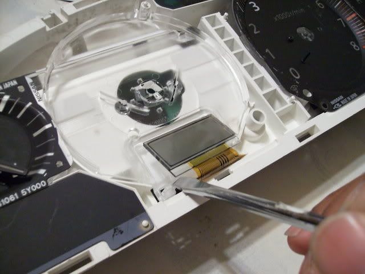
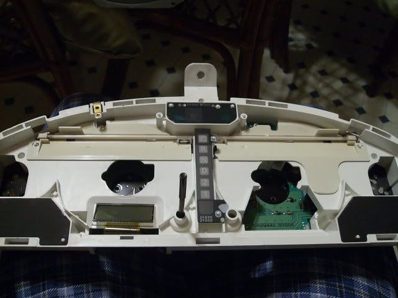
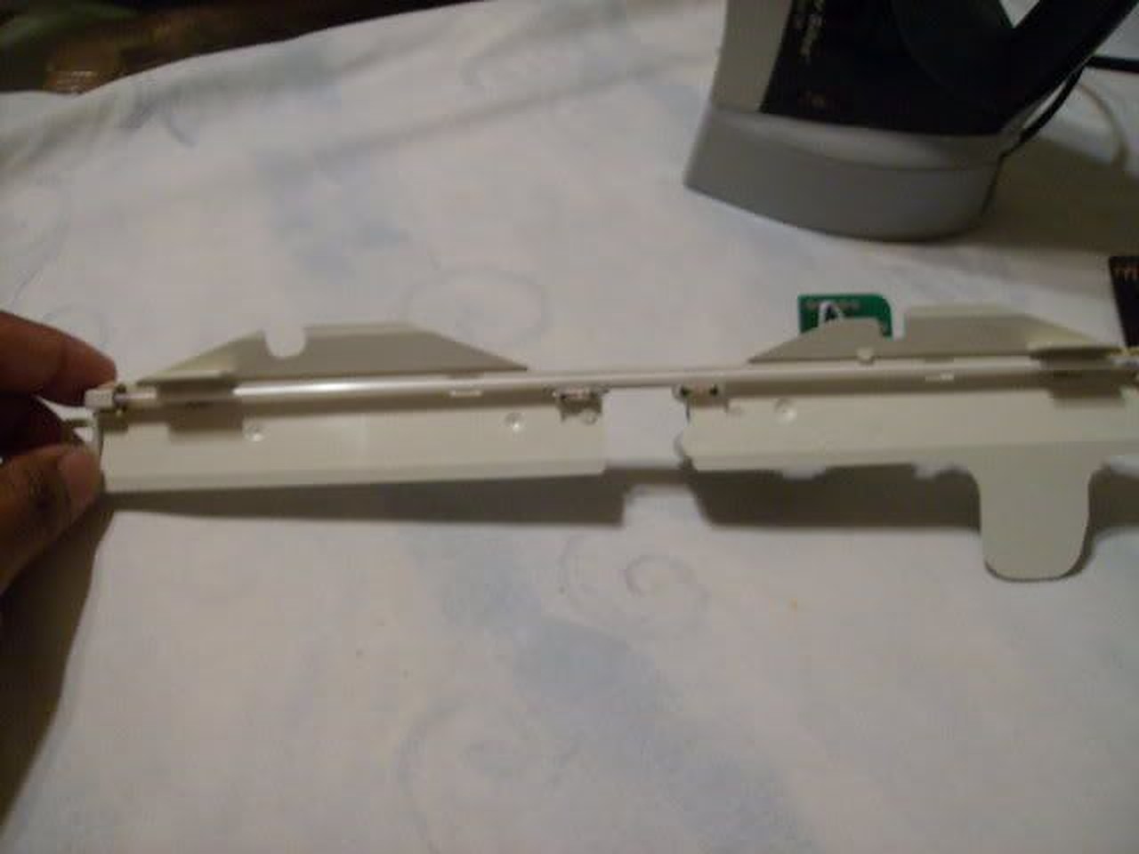
8. Here is the EL tube and all it’s glory…

9. These are the screws to remove the EL tube…

10. Pull up on the tube assembly and it should come out of the cluster’s circuit board.

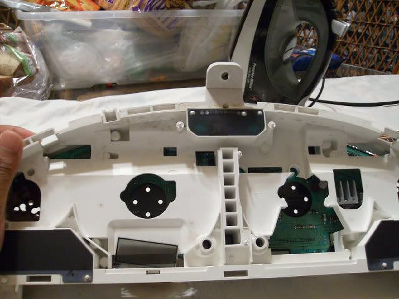
11. Here is the room you have to work with…it’s not much, but the LED strip I ordered from http://www.oznium.com/led-flex-strips fit like a glove. I used super glue to hold it together. Also the wires from the LED strip can be snaked through the holes left from the EL tube screws…

12. Put everything back together and tighten everything up. Use a 9V battery to make sure the strip lights up…

13. With everything back together…

It’s wasn’t bright at all (especially in the daytime) but it was on a 9V battery so…

I decided to wire it up to the cigarette lighter…yes the gear shifter surround has to be removed and the radio/ climate control too, or enough to get to the cigarette light wires…

Wire the LED strip wires together with the cigarette lighter and put key in ACC to make sure it lights…it’s very bright in the daytime… Especially at night they are amazingly bright!

Additional Helpful Information by raincity

After only 4 years my replacement CCFL had dimmed to the point that I couldn’t see the display when the car was very cold. It was only poorly visible even when warmed up so I decided to finally install LED’s. I did this with a bit of hesitation because I could not find the cluster wiring points for LED’s posted anywhere, despite hours of searching. With some work I was able to figure it out.
The LED strip and an extra connector was purchased from superbrightleds.com for less than $20 with shipping.
1 – NFLS-NW30X3-WHT Natural White LED Strip (includes 1 connector)
1 – NFLS10-2CPT Pigtail Connector

The LED strip has adhesive backing and can be cut every 2″. I pulled the old CCFL, associated wiring and circuit board and mounted two 4″ strips right to the CCFL plastic mount, one on either side of the transmission display. I placed them as close to the outside edge of the plastic as possible. They fit almost perfectly, only a tiny piece of plastic had to be trimmed from the mount. The wiring from the strips fit into the same run that the CCFL wiring ran through. I soldered the wires together.
I wanted the wiring to remain contained inside the cluster so I spent a few hours examining the schematics in the FSM and found the correct wiring points:

The wiring connection points are on the plug labeled M34, shown on page EL-145 of the FSM. It is fairly easy to solder wires directly to the pins on the base of the connector if you tin both the wire and pin first.

The negative LED wire connects to pin 49. That lead connects directly to the Illumination Control Switch (the dimmer control.) The FSM pages showing the wire endpoints are EL-120 and IL-123. The path of the wire runs across multiple pages of the schematic.

The positive LED wire connects to pin 66. Pin 66 connects to a 12V source that is controlled by the ignition key. It’s shown on manual page EL-147.

The results were well worth the time. For the first time the cluster lights look like they should, clearly visible in bright daylight even with sunglasses on. The odometer is also clearly legible all the time. When the headlights are turned on the cluster LEDs dim exactly as they should. The color of the LED strip is also excellent and lacks the purple hue of the last CCFL bulb I installed.

The only negative is very minor. The lighting across the display isn’t quite as consistent as it was with the CCFL. It is a minor variation and I don’t think I would have noticed it at all if I hadn’t been looking for it.

Good luck.

Update: After driving the car for a few days in the daytime and being very pleased with the brightness of the display, I drove last night after dark. The new LED’s are so bright that to get them down to a reasonable level at night requires turning the dimmer way down, too far down to clearly see the other displays that are also controlled by the dimmer. Unfortunately it won’t be possible to contain fully contain the wiring withing the cluster and maintain the daytime brightness without adding a custom circuit. To allow the independent control of the cluster LED’s I’ve decided to add a 2nd dimmer switch dedicated to the LED lights. Ebay had one for $12 shipped and I have an empty spot in the dash to install it so it looks like a stock control. I’ll post back here with results.

Loading

Member Credit: yellow_cake

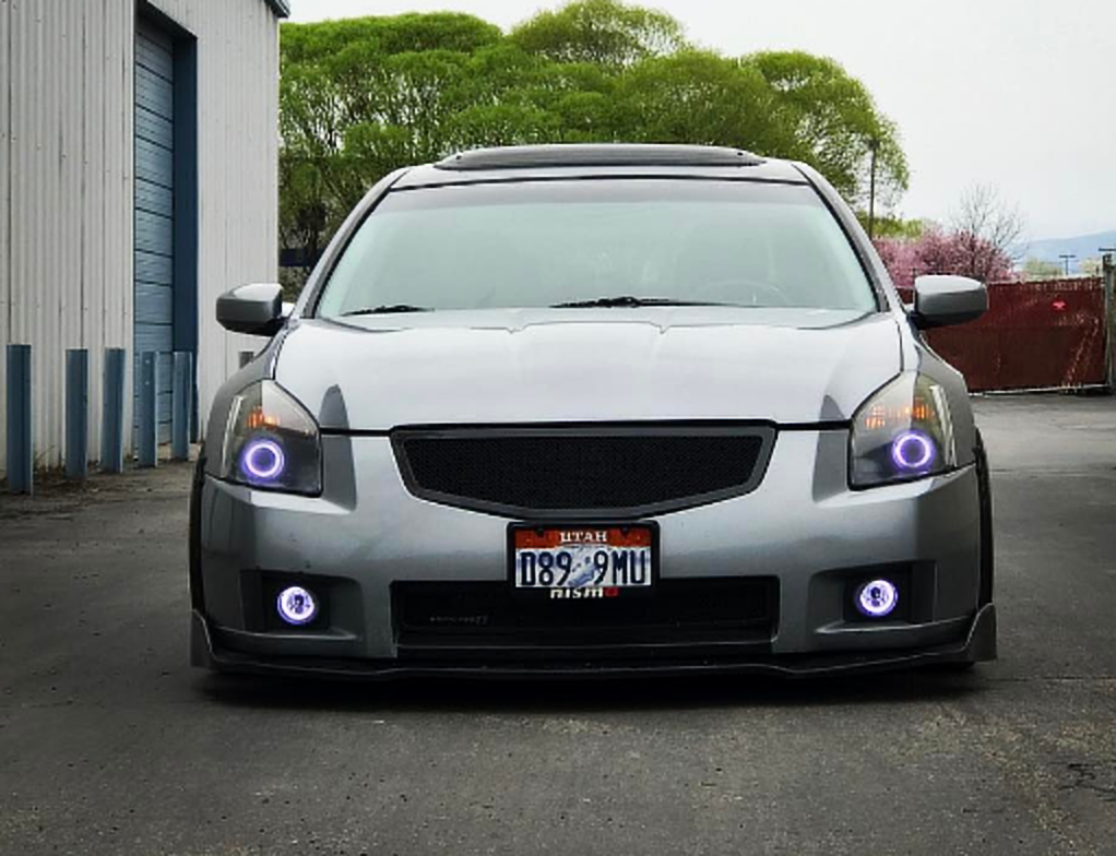
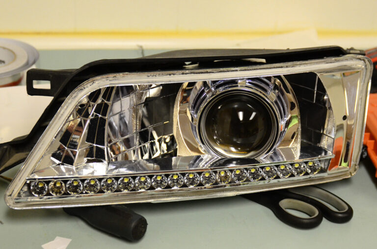
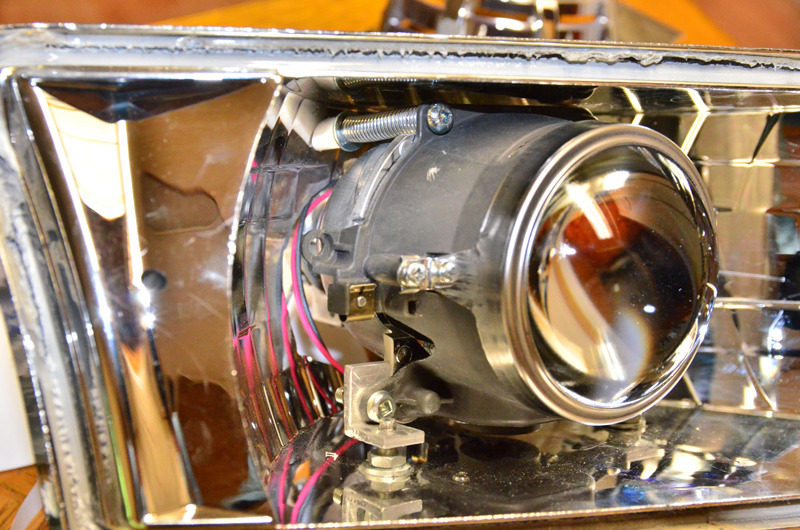
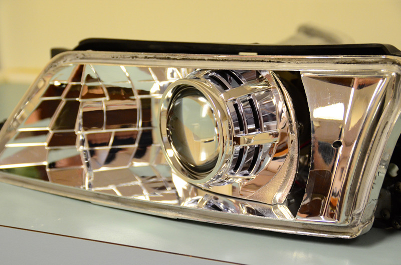
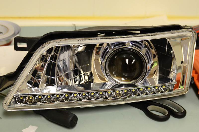
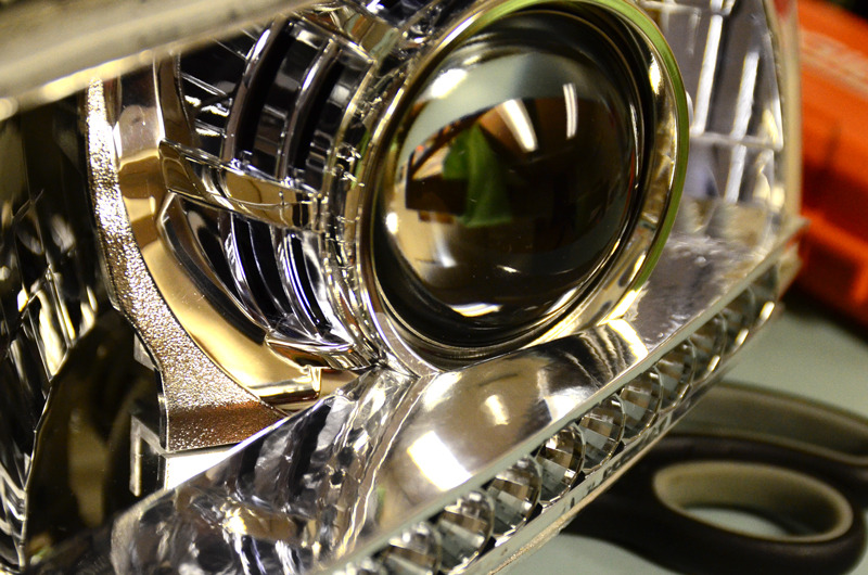
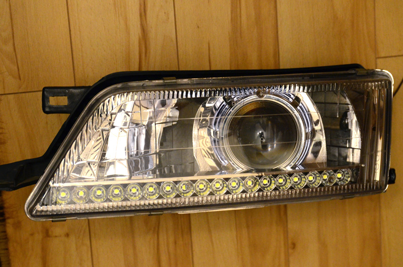
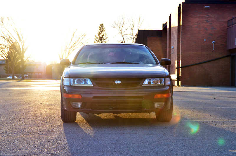
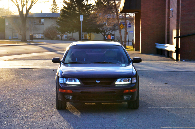
Hi folks, just thought I’d share my retrofit project on my 99 Maxima.

Components:
– Used Depo headlights.
– G37 sedan projector.
– ’13 Cadillac SRX semi-clear lens.
– OEM G37 shrouds.
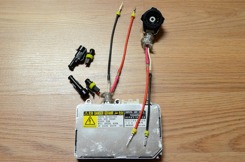
– Denso Slim ballasts.
– Osram CBI 66240 bulbs.
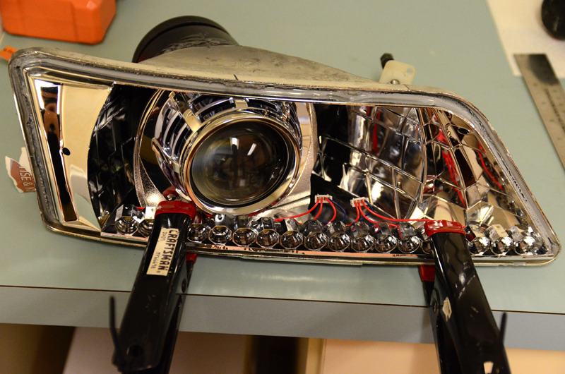
– Nichia Superflux white LEDs.
– exLEDs reflectors for superflux LEDs.
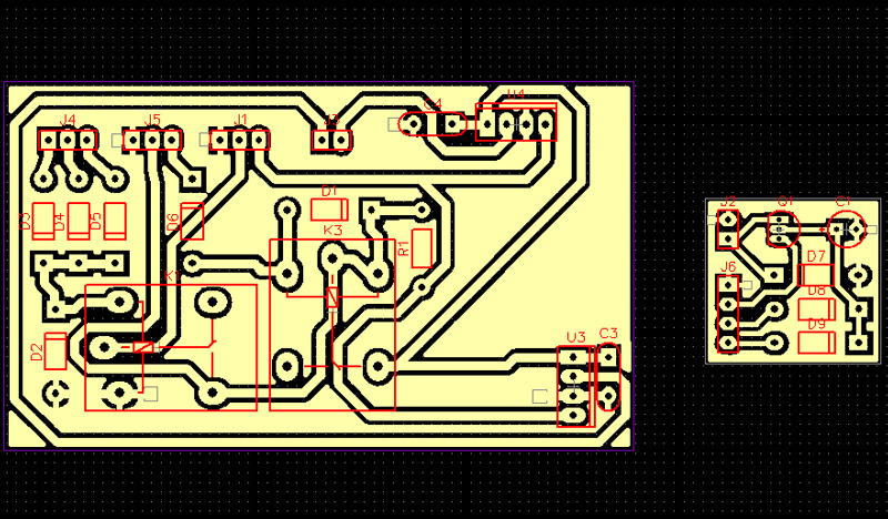
– Custom wiring harness + DRL & headlight controller.

Mounted using the JNC method, giving minor rotation and height adjustment on top of the factory reflector adjusters (vert + horiz).
For more info about the JNC mounting method: http://www.hidplanet.com/forums/show…model-pictures
Name: DSC_6315_zpsniwiyhzy.jpg Views: 458 Size: 198.3 KB

OEM G37 sedan shrouds fitted.
Name: DSC_6424_zpsy86jetgf.jpg Views: 412 Size: 156.0 KB

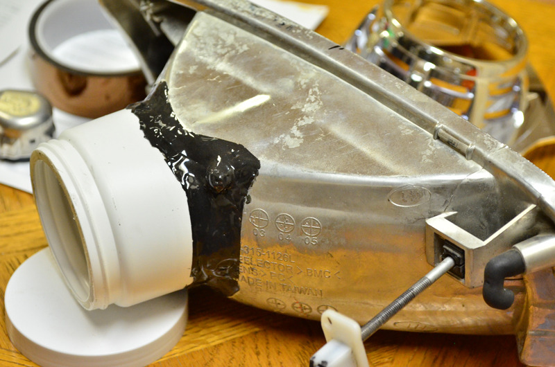
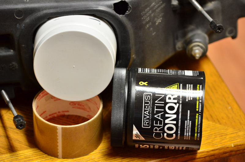
After cutting the container, I used lots of JB weld to secure it into place.
Not shown, but there is also a bunch of epoxy around the inside for added strength. For that I used a self-mixing syringe type clear epoxy.
Name: DSC_6302_zpscv6dde42.jpg Views: 357 Size: 146.1 KB

Here it is, fitment with the reflector mounted into the housing.
The empty containers were from workout supplements; different colours, but both were identical in size.
Name: DSC_6311_zpst4jlgrmj.jpg Views: 336 Size: 134.6 KB

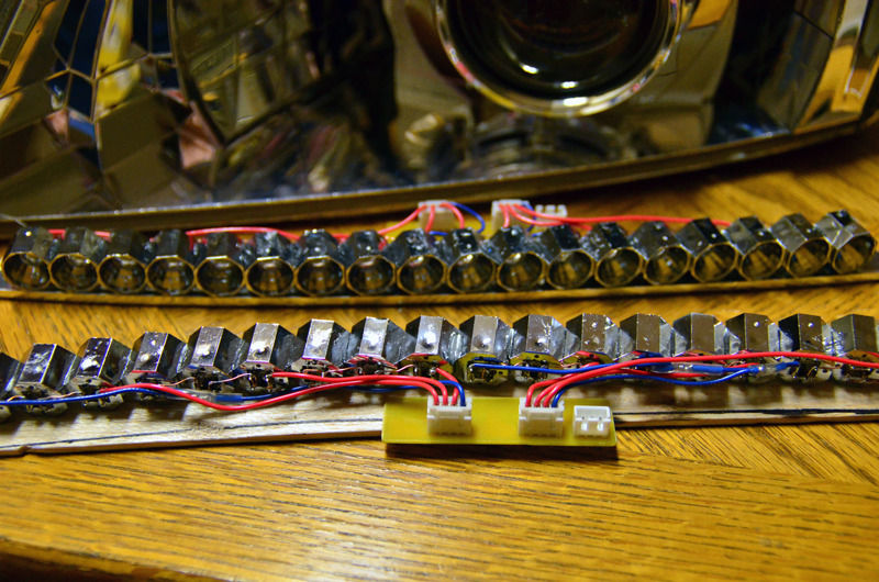
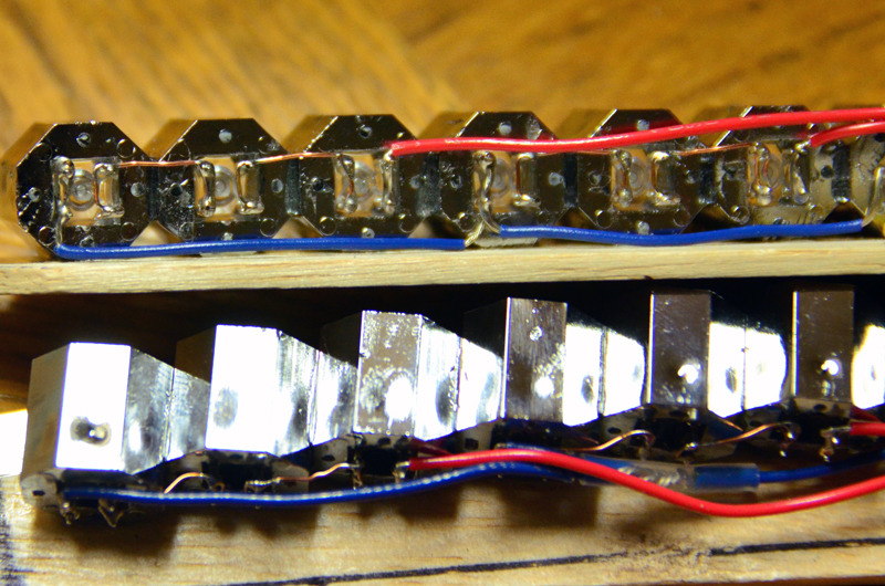
I used a sheet of balsa wood for the base, with some chrome vinyl for the front edge which will be visible.
The LED were secured into the reflectors with epoxy; the reflectors secured to the base & one-another with clear epoxy.
Name: DSC_6274_zpsvewxgibc.jpg Views: 357 Size: 212.9 KB

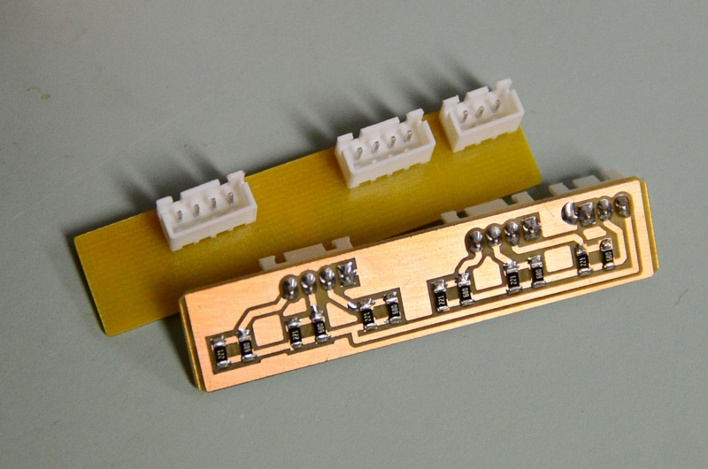
Home-made resistor array, clear-coated after everything was soldered to prevent the copper from oxidizing.
Name: DSC_6440_zpshiwqmqhy.jpg Views: 350 Size: 120.1 KB

Name: DSC_6276_zpsiucgpwtx.jpg Views: 335 Size: 186.8 KB

Epoxy’d the DRL base into place.
Name: DSC_6431_zpsypfghzkc.jpg Views: 394 Size: 176.0 KB

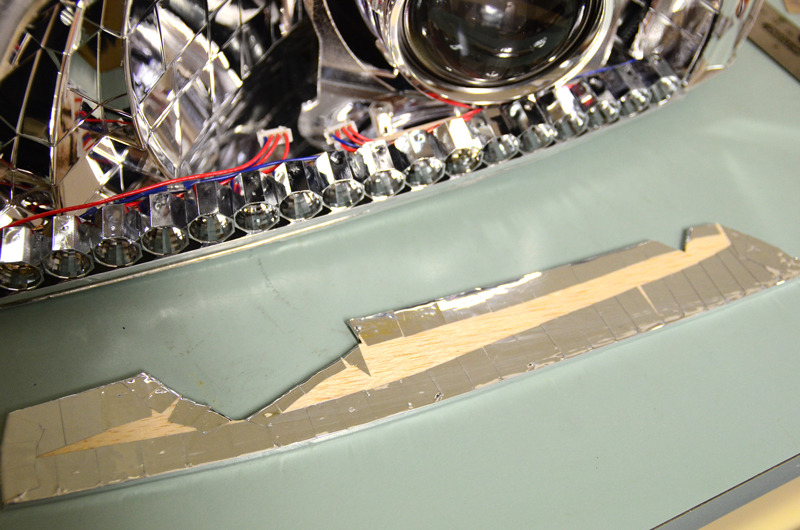
Cutout the top cover, also made from a sheet of balsa wood. Showing the bottom view where the chrome vinyl wraps around.
Prior to mounting, I spread epoxy all over to prevent the edges of the vinyl from lifting.
Name: DSC_6433_zpsxfnfvr4t.jpg Views: 380 Size: 153.4 KB

Epoxy’d the top cover. The reason I used chrome vinyl is so that the DRL assembly flows well with the rest of the headlight.
Name: DSC_6445_zpsrx920vb5.jpg Views: 350 Size: 163.7 KB

Close up of fitment.
Name: DSC_6446_zpshfidfuvi.jpg Views: 328 Size: 192.2 KB

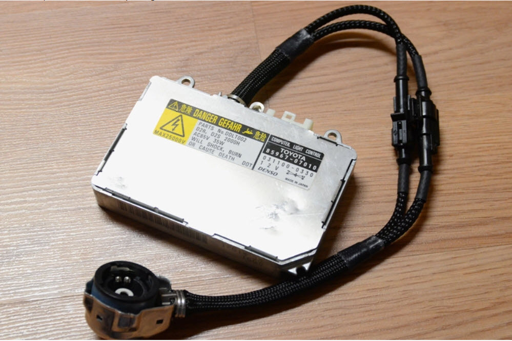
The Denso slims had the short cords, this would be problematic for most retrofits…
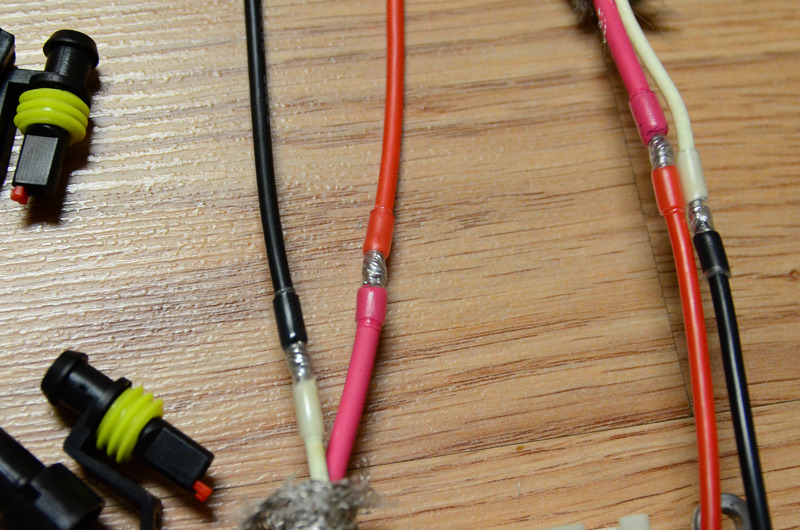
I extended the wires while making the ballasts D2S/AMP hybrid. This will make headlight removal easier as well.
Name: DSC_6468_zps709gl5yn.jpg Views: 324 Size: 177.3 KB

Soldered + adhesive lined shrink tubing. Notice how the solder joints offset one-another, good practice in case the joint or insulation fails (which it shouldn’t, lol).
Name: DSC_6469_zpskeu7atqn.jpg Views: 350 Size: 186.2 KB

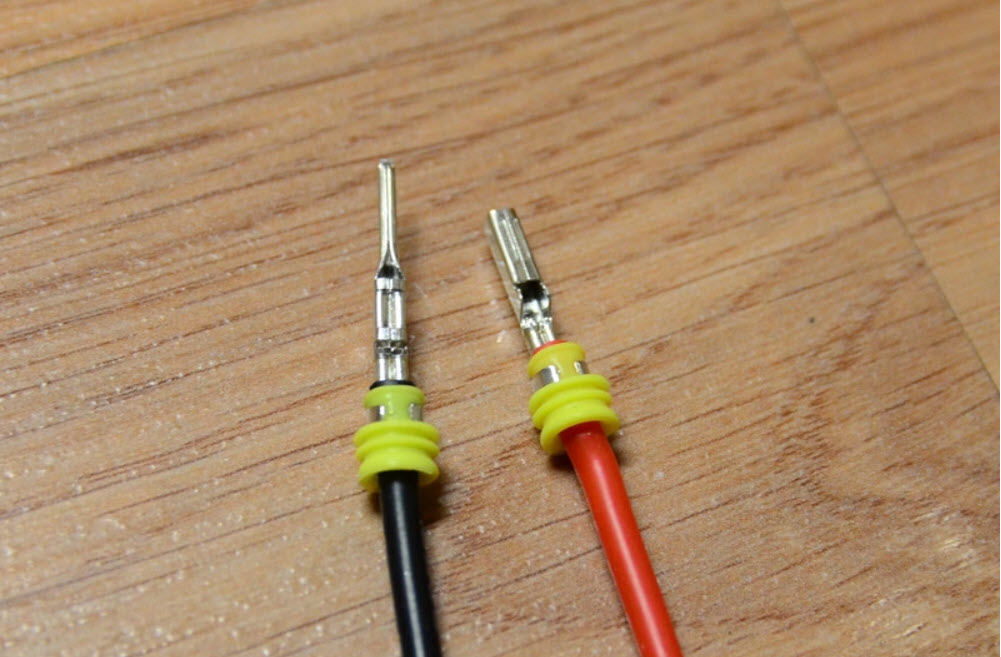
Terminals crimped on.

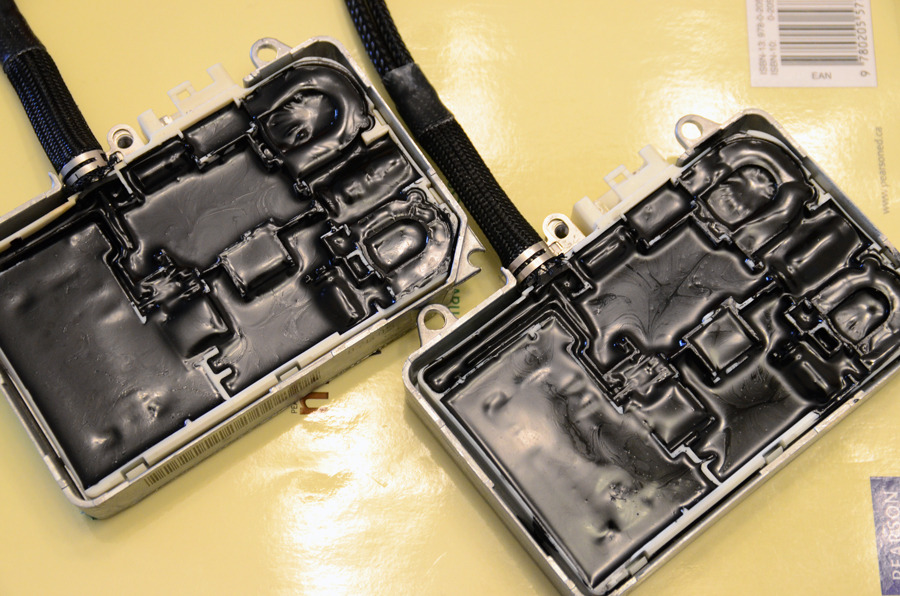
Ooooohhh, aaaahhh… I’ll be potting the ballasts as well.

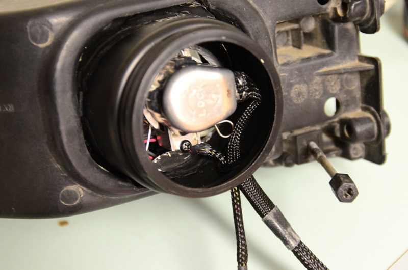
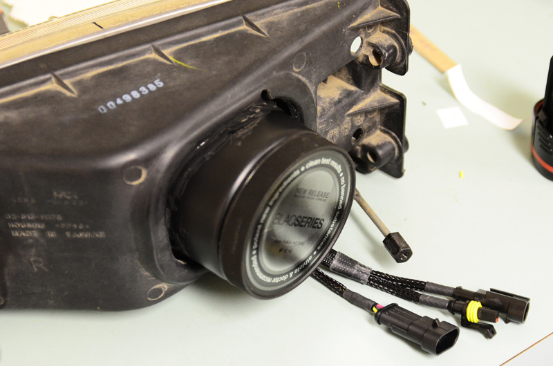
Wires fished out through a rubber grommet.
Here’s the wiring setup: The one loom has the DRL + solenoid wires, the other has the ballast cord.
Name: DSC_6476_zpsd1a8bwpp.jpg Views: 354 Size: 114.0 KB

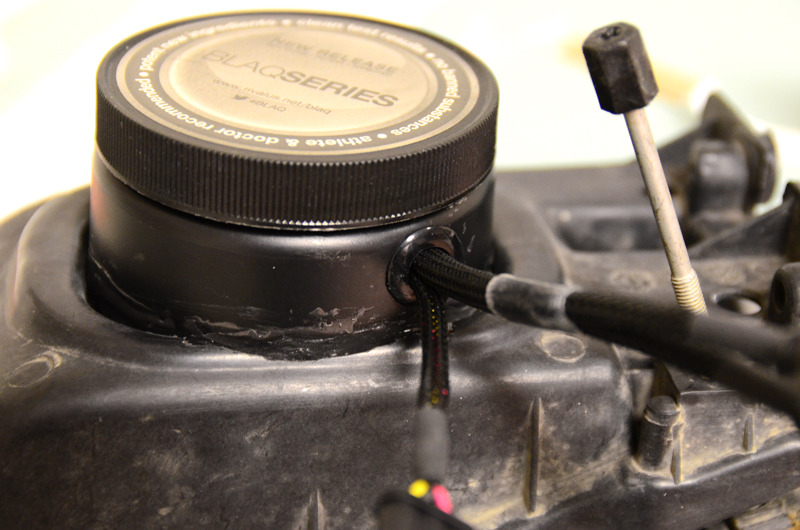
Cap screwed on, sealing the back from dust/water.
The 3-pin connector wires: solenoid positive, ground, and DRL positive.
Name: DSC_6474_zpsotdng89f.jpg Views: 335 Size: 112.5 KB

The rubber grommet at the bottom.
Name: DSC_6477_zpsiifryxrf.jpg Views: 369 Size: 122.5 KB

Headlight completed!
Name: DSC_6482_zpsdcuxr7mf.jpg Views: 315 Size: 176.7 KB

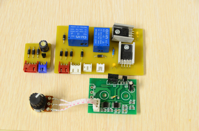
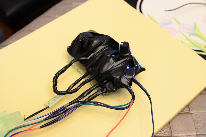
Here’s the custom DRL controller + headlight controller.

The DRL controller has a dual brightness mode via an external PWM (ebay). Also, I’ve made it so engaging the e-brake will disable the DRL, just like the stock DRL. This will give me the ability to pull the handbrake up one click and have the DRLs off if I need to be stealthy, lol.

On the right is the low+high beam controller. basically it’s a delay off circuit. Meaning, if the headlights are on and then turn them off, it will take about 2 seconds to shut off… I did this mainly for flashing while the headlights are off. This way it’s not flashing the ballasts as they remain on in between flashes.
Name: DRL-headlight_controller_zpse6mnqqvz.jpg Views: 360 Size: 201.0 KB

Ebay PWM at the bottom.

Potted the Denso ballasts.
Name: DSC_6484_zps9upsmorf.jpg Views: 381 Size: 209.9 KB

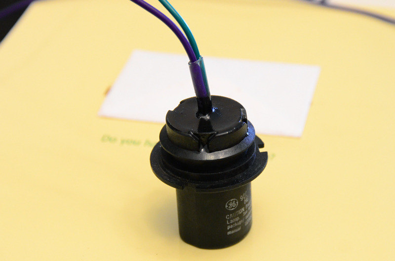
Made a 9004 “connector” out of an old bulb. Removed the bulb and soldered wires onto the pins, then filled it with potting compound.
Name: DSC_6487_zps8omya040.jpg Views: 335 Size: 60.8 KB

Eventually I plan on making an Arduino controlled DRL/headlight controller, it will have a fancy aluminum housing… For now, I’ve got the current setup wrapped in electrical tape… yea, it looks like a grease job, LOL.
Name: DSC_6488_zpst4pfmosu.jpg Views: 384 Size: 104.4 KB

Installed.
Name: DSC_6506_zpsj2vc0yas.jpg Views: 350 Size: 171.1 KB

DRLs on:
Name: DSC_6499_zps1cqiqgqz.jpg Views: 442 Size: 436.9 KB

LEDs are dimmed when parking lights come on.

Low beams on:
Name: DSC_6502_zpsldgvtz5p.jpg Views: 345 Size: 182.5 KB

I don’t have output pics at the moment, but I’ll get them in the next few days.

Loading

Credit: Fezzik (David Honey)

This is the How To on the installation of heated mirrors. A few things first before I go on. I have the automatic climate control with the rear window defogger switch on it. The side view mirrors are linked to this switch. For those with manual climate control, I assume that it is also linked to your rear defogger switch (RichK on maxima.org said he got the same reading as I). Total costs are as follows quoted from Dave Burnette (1-888-254-6060):

Mirror Heater Relay = $12.22
Side view mirror glass with heating element only = $45.72 per side

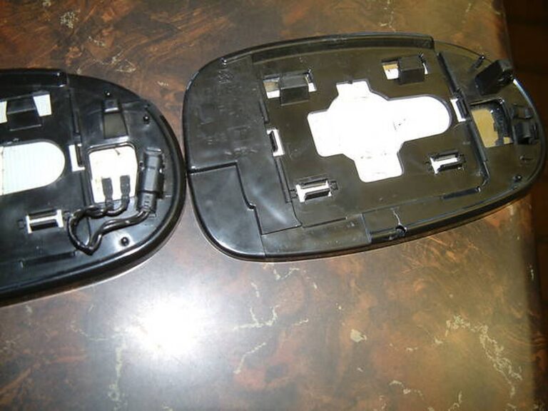
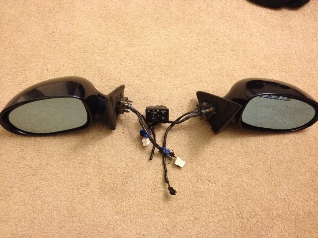
First of all. Make sure you do not have the heated mirror option. To make sure, you can either press the rear window defogger switch and put your hands on the mirror to see if it gets warm or pop off your side view mirror glass and see if you have wires running to the mirror itself. If you do, then you have this option already. The picture below is one showing the difference in the two mirrors. The right does not have this option and the left mirror does. You will have to purchase the mirror on the left because it has a heater element built into the glass mirror.

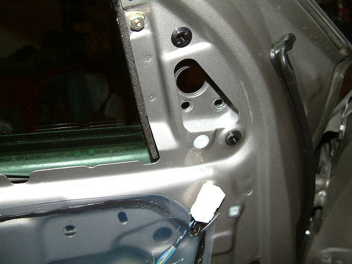
If you do not, then follow these instructions to get them. First of all, open your hood and when looking at the engine bay look to your left and you will see a black box that contains some relays. Open that up and find the corresponding spot for the heated mirror (it says on the black box where its at.) If you have a spot to put a relay in then all is well so far, and later you will have to buy the relay or in my case I had a nice surprise and already had the relay there. Ok the next criteria you need to find out in order for you to proceed is to take off your door paneling and look at the wiring harness going to the side view mirror (see below pic). The big black plastic piece is the cover to the side view mirror. There are 3 wires (yellow purple and dark blue) going into this and into the side view mirror. There are 3 wires corresponding to these wires on the other side of the connectors. Now take note of the other 2 wires (Green and light blue) coming out of the top right two holes. There is normally nothing here, but on the corresponding other side there are two wires leading up to these.

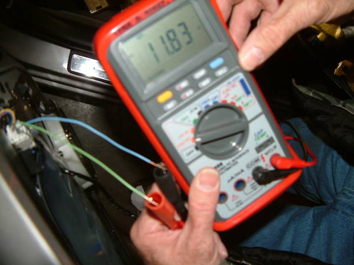
These are the wires that are pre-wired for the heated mirror. I tested this theory out by hooking up a voltmeter to the wires that I put in the top right holes. (I originally had the connector in the above picture disconnected and tried to test the voltage on the 2 small pins and that was too hard to do. I shorted the circuit and blew fuse 13… so do like I did above. SO much easier). When plugged into a voltmeter and with the rear defroster on I got around 12 volts (sorry about the blurry pictures):

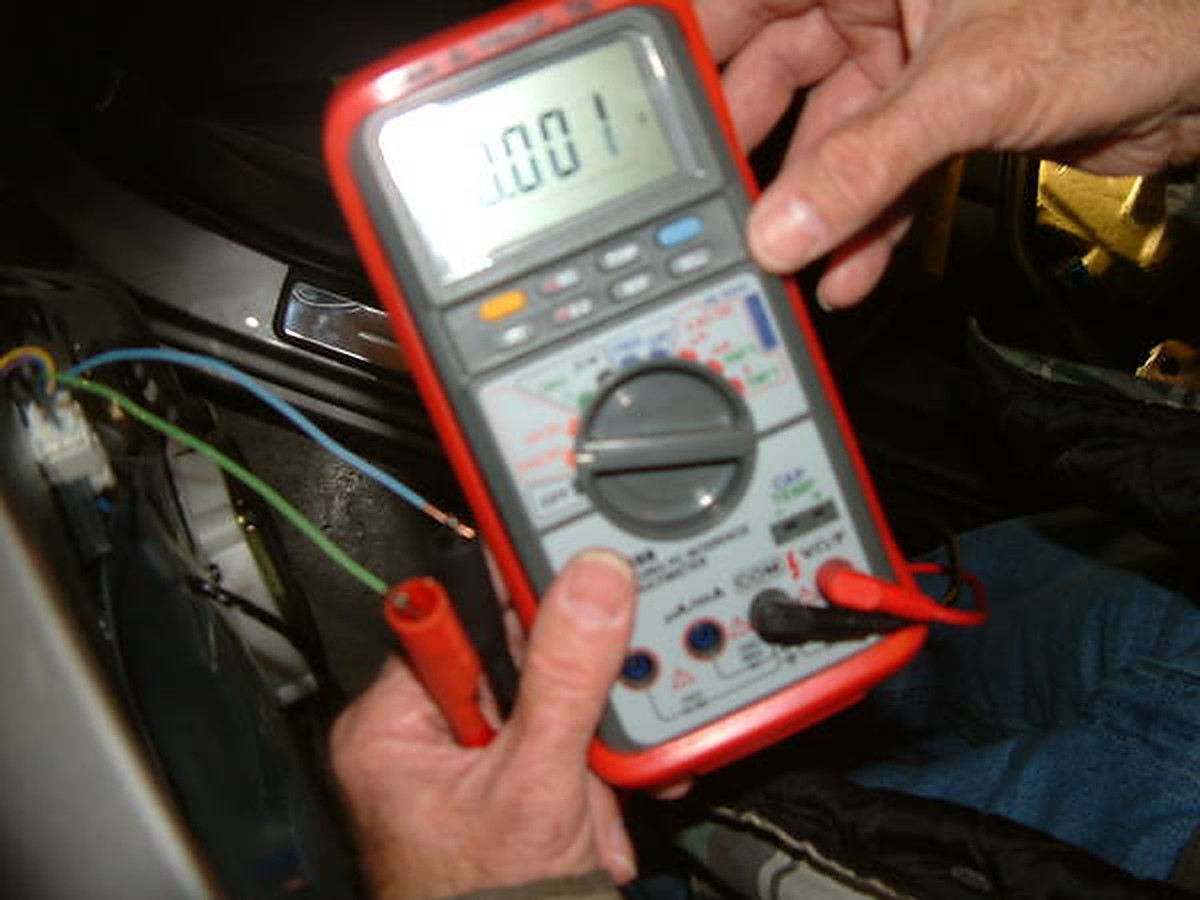
And with the rear defogger switch off reads 0.001Volts:

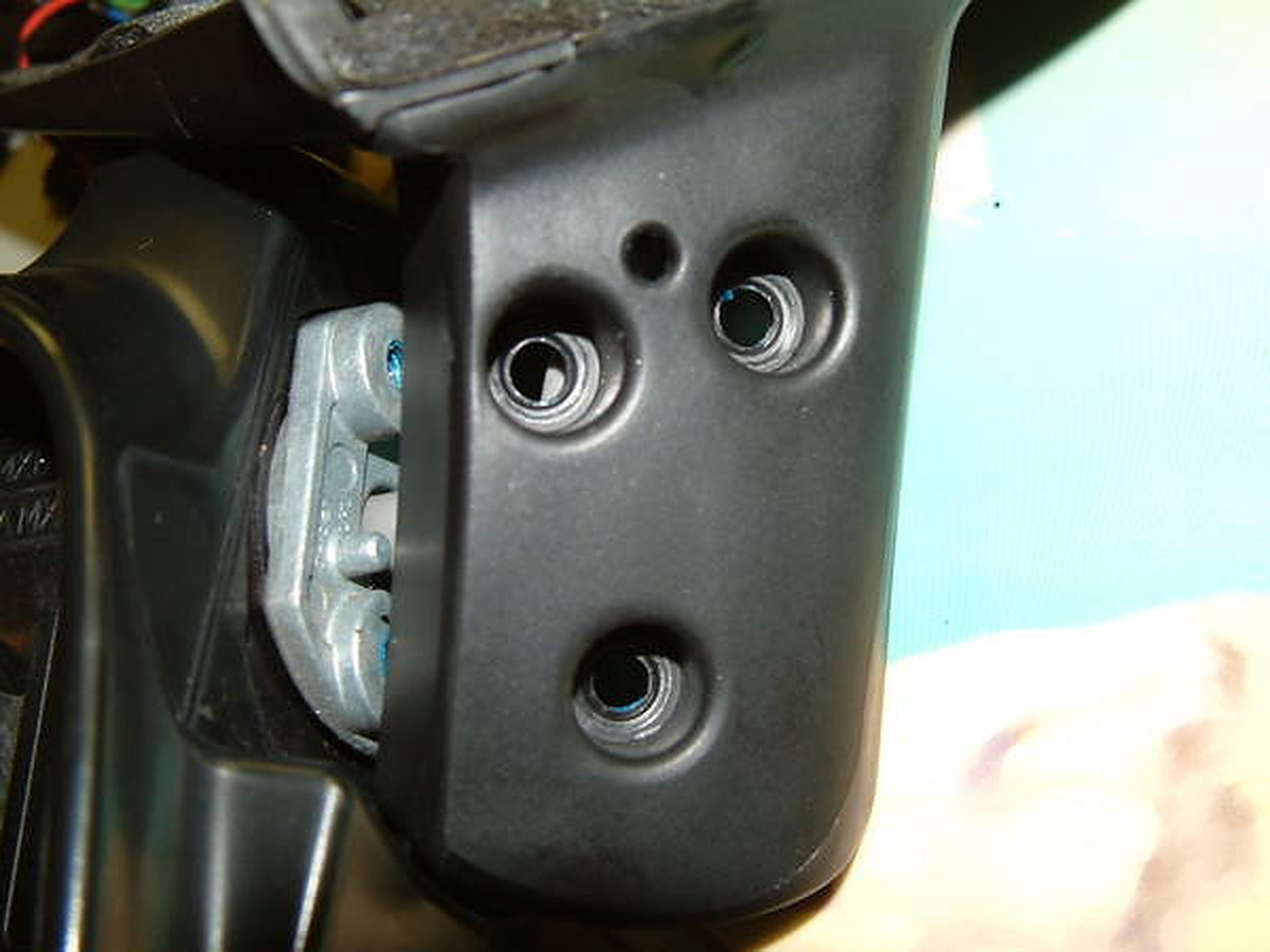
The next step is to take off the black plastic cover that is covering the side view mirror bolts (same plastic cover as seen in the above picture that the 3 wires are running into.) Unplug the connector, and take off the three bolts that are holding the mirror onto the door.

What it looks like with the mirror off (inside). Also notice how many wires are running into this connector. Look below the black tape. 5 of them.

Outside view with mirror off:

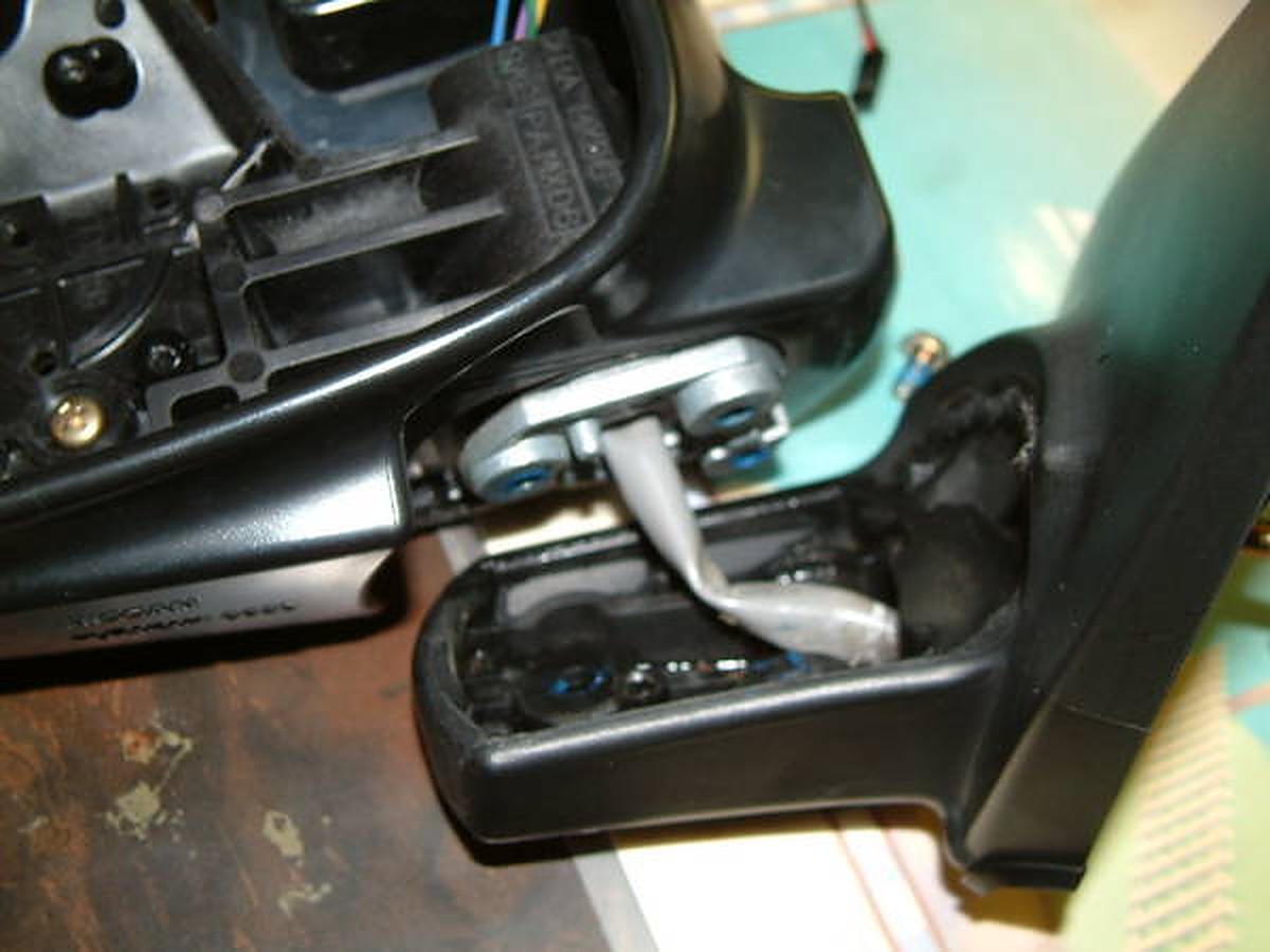
Now you have to take out the 3 screws that are below the side view mirror.Notice the blue. Yep that’s locktite. I striped the head of the screw on the passenger side and took me 2 hours to finally get it out. SO BE CAREFUL TAKING THESE OUT:

Here is the assembly all apart:

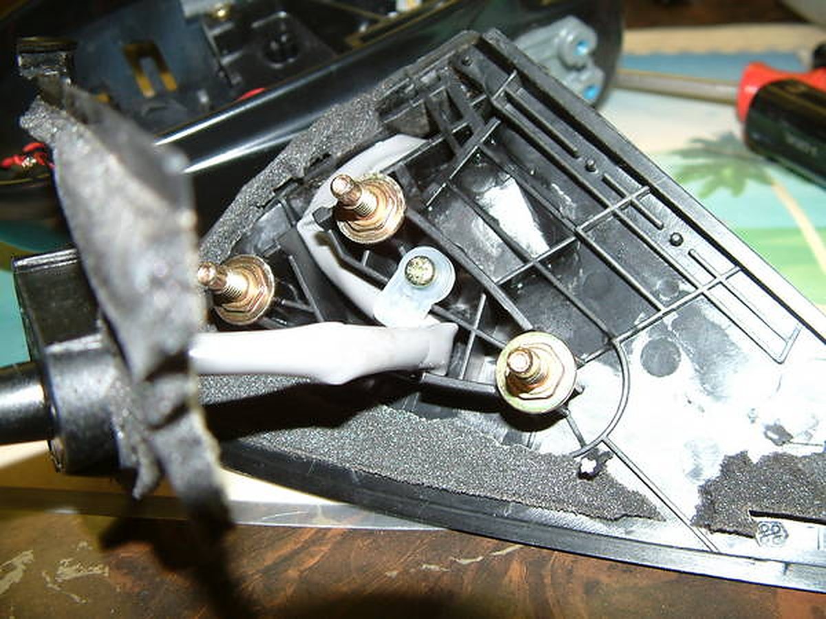
Now look at the part of the side view mirror that faces the car the part that has the 3 places to bolt onto. There is a cover on this that you have to take off. The insulation is glued on there so your going tear that. Nothing you can do about that. Look below how I tore mine. Unscrew the thing that is holding the wiring harness in place.

I apologize but I forgot to take some pictures from here on out. It was getting late. But now, you can have full access to this gray tubing. Remove the actuators (the things that make the mirror go up and down, right and left) from the side view mirror. This is held on by 3 screws. When you take this off you will see 4 wires. Didn’t I just say there was 3 wires going to the side view mirror. I did. But one is spliced somewhere in the gray tubing. Dave Burnette (You maxima guys should know him) and I were talking about this for awhile until I finally found out the reason The ECM even shows 3 wires but if you look inside the actuator, there is a wire that is split. Ok back to the subject at hand. Remove the 2 connectors (gray and black) from the actuator. Remember which go where. I marked it with scotch tape. Now the wiring can slide down the tube that is inside the mirror. Wish I had a pic of this but you will see what I am talking about. Now you can run wire through the gray tubing easily.

First I ran 2 wires long enough to reach from the other end of the side view mirror where the heater element connector is to reach all the way to the connector in the door panel.To run wire through this gray tubing was tricky, but I used solder wire. The stuff that’s flimsy. Well, it’s stoutenough to push the solder wire through the grey tubing. Then I tied ( you may try taping it) to the wire and pulled it through. You now have a wire going all the way through. Now put everything back together the way you took it off. I did not worry about the insulation from the above picture because it all went back and even though it is torn still covered everything up. Now that everything is back together you now have what you started with but, now with 2 wires running through the mirror. Here’s the part where I had to get creative. You have to have a metal pin connector to fit into the big plastic connector. Luckily I have a storage area of computer parts and wiring harnesses from computers. I actually got the 2 pins I need from a 1985 Honda Accord radio wiring harness for aftermarket systems. Lucky me. Now all that leaves is the connector for the side view mirror. Take a look at it below:

Of all things I found to fit into here… it was a long computer jumper. Sorta like the audio cables you plug from your cd drive to your sound card, but I had a 2 prong one. With a little bit of firm pressure it fit right in and quite snugly. Popped the mirrors back into place and I now have heated side view mirror option on my car. Supposed to snow soon. Can’t wait to try it out.

Special thanks go out to my dad for helping me decipher the wiring diagram on the ESM and reading the voltage, and to Dave Burnette for his time in this as well.

Loading

Member Credit: Douglas Sands / CGR$ Engine Initiative

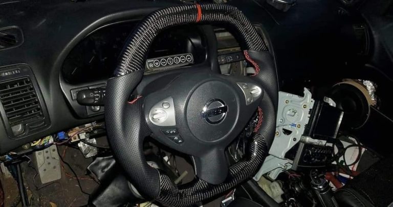
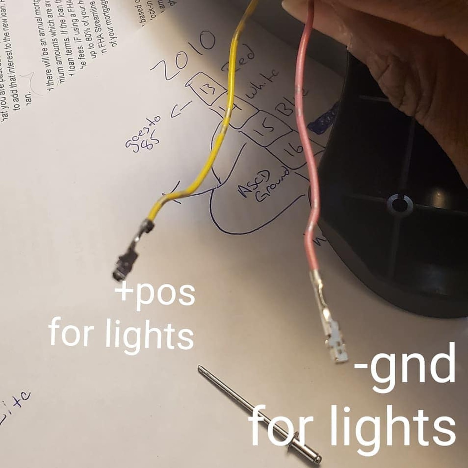
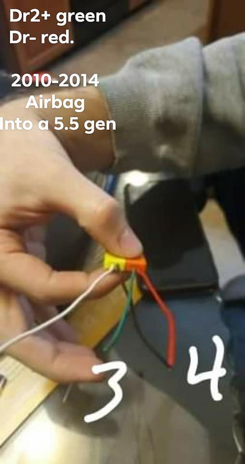
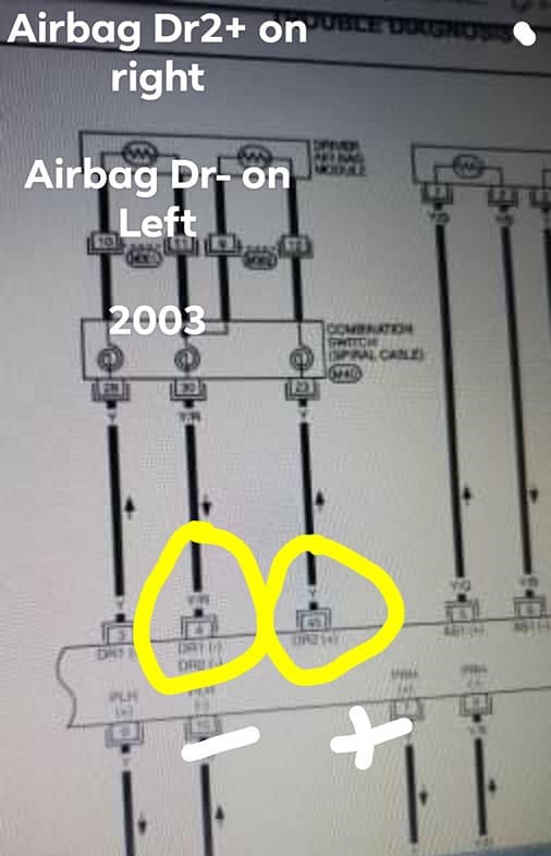
So you can use this info to set up whatever vehicle wheel to the 2003 Nissan maxima. This is a direct plugin for a 2009-2014 Maxima or 370z. I went with the max for the airbag symbol, didn’t need a huge z on my wheel.

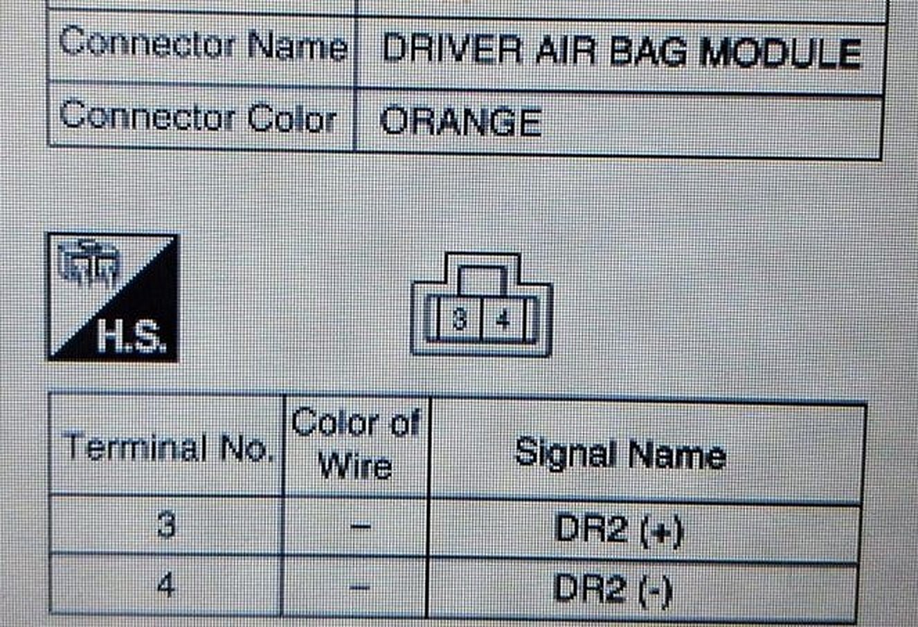
These are the pin positions inside the vehicle. Just do the same for the other vehicle, and match them to their function. As long as the clockspring connector is the same just set it up and plug it in.

Empty 13 Empty
Mode 14 White
Volume 15 Blue
Ground 16 Brown
ASCD Ground 17 Black
ASCD Switch 18 Red
Empty 19 Empty
Horn 20 Green
2007 Horn to 2003 Clockspring

Loading

Member Credit: vastmax

I acquired some genuine TDM Nissan mirrors a while ago with the convex glass, sidemarkers, puddle lights, heated, and of course, folding functionality.

I ran my wires from the door to inside the car through a small grommet that is located right beside where the bundled door wires go in. You can access this from the wheel well if you take the wheel liner off. When wiring the folding function to the switch itself run the (+) and (-) to the switch for one of the mirrors, then tap those wires for the second mirror. The (+) wire goes in the blank 2nd spot and the (-) wire goes to the last hole on the bottom row of the molex. Also, I noticed while looking through the FSM that I believe that all the heaters need to work is the heated mirror relay under the hood. I’m 90% sure all the wiring comes in all Maxima’s. It’s not cold enough here yet top try it out, but someone up north can let me know if that’s the case.

This is how I wired mine and the mirrors worked the first time and still continue to work.

For reference, this is your SECU under the driverpanel

Pin 1: Turn Signal + (BK/R)
Pin 2: Turn Signal – (BK/W)
Pin 3: Puddle Light – (BK)
Pin 4: Puddle Light + (BK/Y)

In addition to the harness:
Power folding: + Pink, – Orange
Heater is Green and Blue gray but I can’t remember which is + or –

Loading

Member Credit: CRiME

What’s up guys,

Following up from 95maxrider’s awesome door lock actuator thread. So My ’99 developed an issue wherein all of the locks would only lock / unlock halfway. The problem got worse with the cold weather, to the point where the rear passenger side door wouldn’t unlock at all. I got tired of reaching around to manually lock all of the doors before exiting the car, so I decided to do something about it.

I figured the actuators were failing – no problem, right? I’ll just grab some from RockAuto. Well, I soon found out that the prices for our actuators have become ridiculous. The cheapest prices for the rears were about $150 each, and the fronts were about $85 each, while the 5th gen actuators are about $10-$15 each. I didn’t want to take the chance on a used JY / ebay part, so I began to look at other options. I found a set of four universal actuators on amazon for $13 shipped, and I took a chance. What’s the worst that can happen, right? if they didn’t work well, I was only out $13. Link to the actuators I purchased is here: Amazon Amazon

They arrived a few days ago and I began the project. I started with the rear d/side door. The universal actuators came with no instructions of any kind. Thankfully, the install for these things is fairly straightforward, and I’ll do my best to recap what I did. If you can install a radio / amp, you can definitely do this.

1) First, you need to remove the rear door panel. If you’ve never done this before, here is a video tutorial, thanks to pmohr:

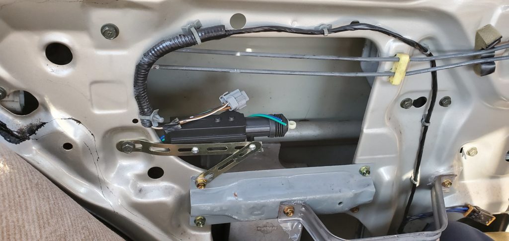
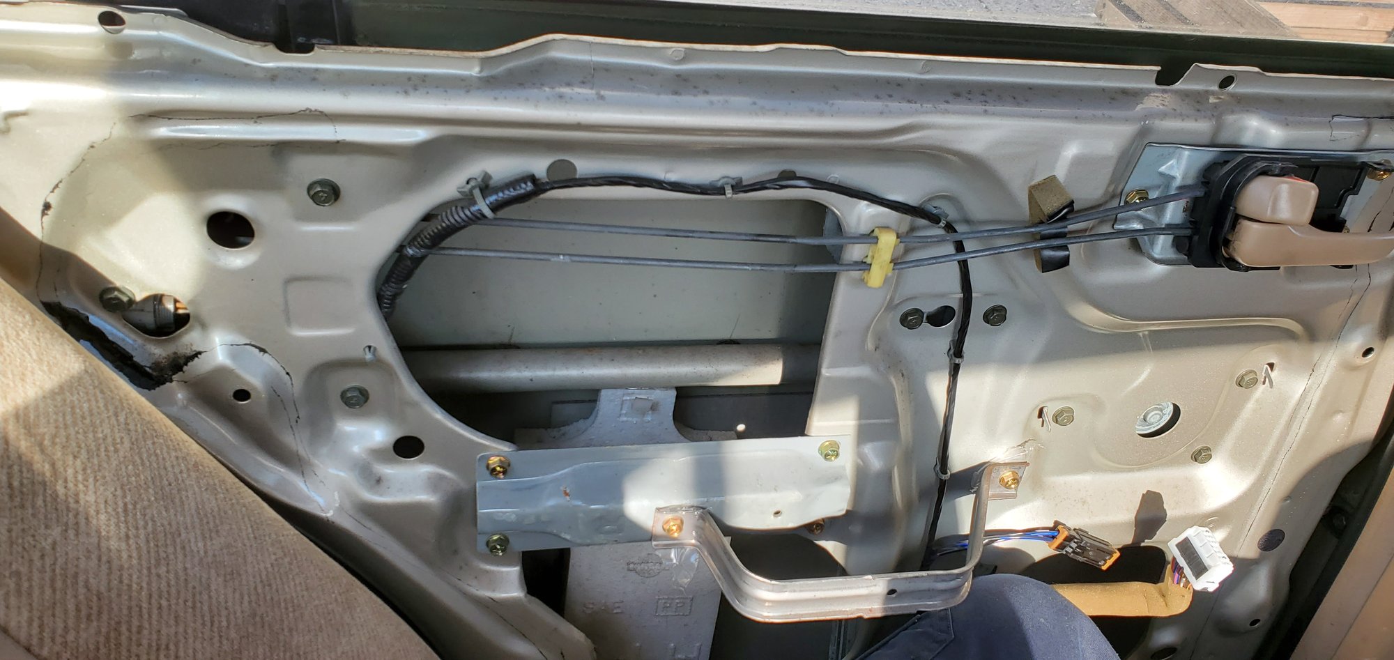
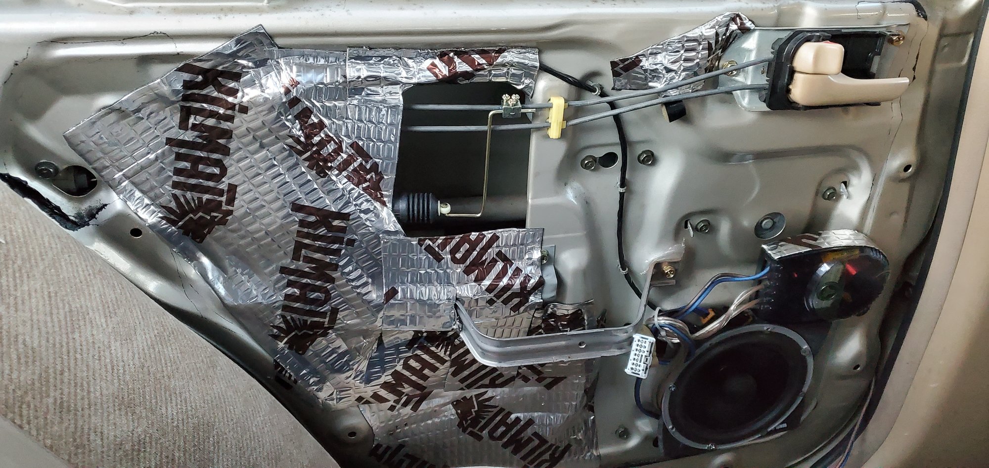
Once you have the panel off, you’ll be looking at this (I removed the factory plastic moisture barrier):

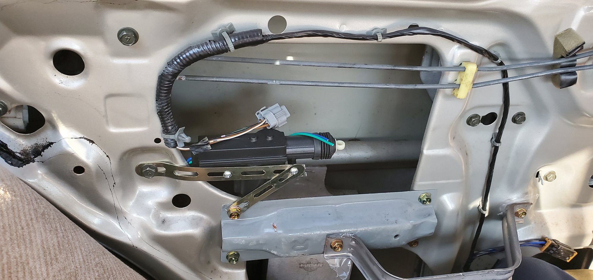
2) The actuator is hidden behind the door frame. You can see its harness through the hole near the seat. I removed the harness by pushing a flathead screwdriver through the hole, to release the clip. Then I used a second screwdriver to pry the harness out while pressing on the clip with the 1st screwdriver. Once I had the harness out, I bolted the actuator into this spot. To get this to work, I had to break the mounting bracket that it came with. This is a great spot for the actuator, because you don’t have to drill any new holes in the door frame. You can attach it to the existing bolts in a V orientation:

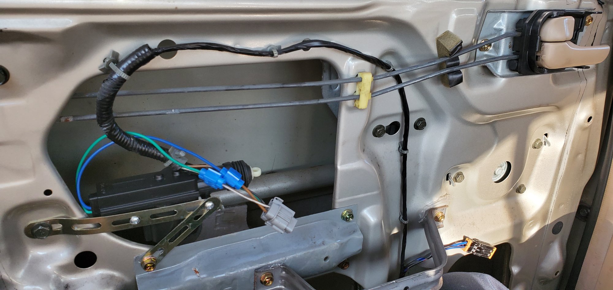
4) On the factory harness, the wires that you’ll want to tap into are the brown / white and solid brown. Connect the brown/white to green, and the solid brown to the blue wire of your universal actuator. The blue wiretaps work great for this

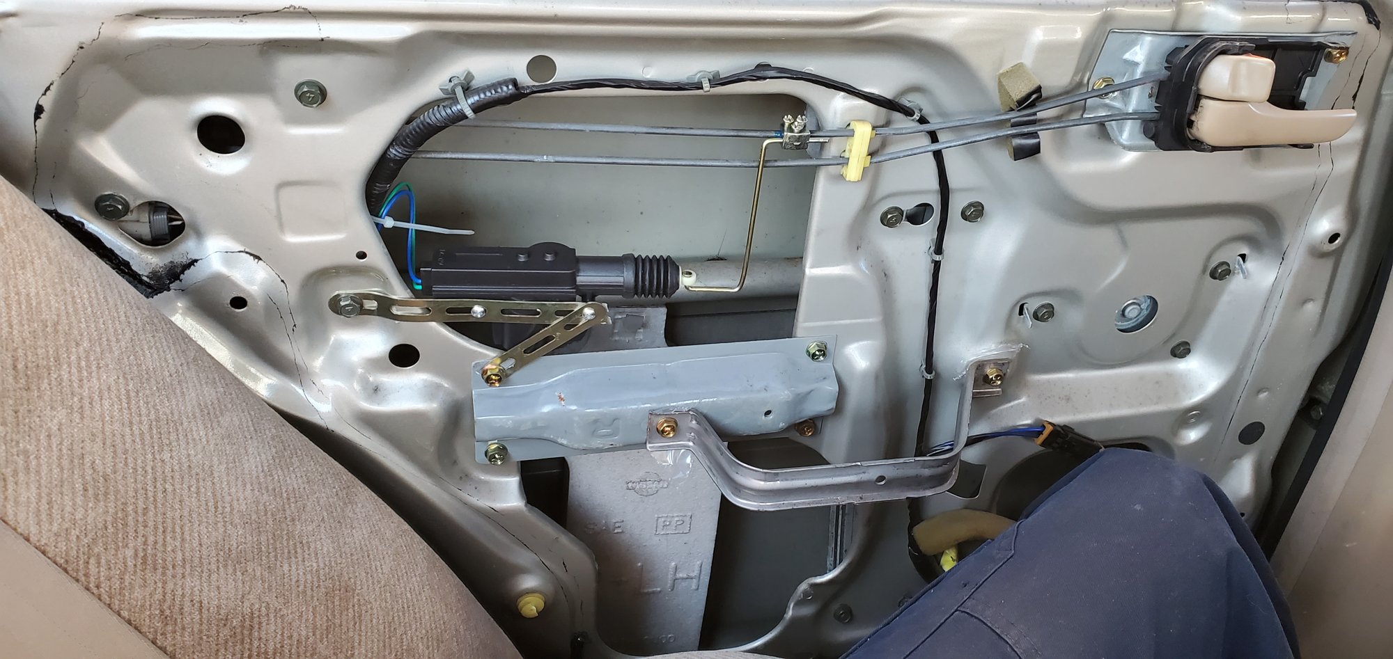
5) Once the wires were tapped, I plugged the harness back into the OEM actuator. This was not even necessary, because the universal actuators are more than sufficient to push / pull the rods, but I insulated the taps with electrical tape and reconnected it anyway. Once your wiring is done, you’ll need to connect the universal rod to the factory rod. I bent it into this shape, fed it through the actuator, and connected it to the factory rod with the supplied clamp and screws. **IMPORTANT** – before you bolt the new rod in, make sure that the orientation is correct – if the lock is OPEN, you want the new actuator to be EXTENDED. if the lock is closed, you want the actuator to be fully retracted. I added some blue Loctite to the clamp threads as well, in the event that the screws somehow loosen up over time.

7) While I had the panel off, I decided to add some speakers to the rear doors, to give my audio some rear fill. I had some coaxials that I had taken out of my previous car, so I decided to throw them in. Slipped a 6.5″ Boom Mat baffle into the hole there to create a tighter seal and also to protect the speaker. I cut out the rear of the baffle to allow for airflow. Bolted the speaker up, wired up the crossover, and fed the input wire out of the existing door grommet, and down through the B pillar into the car. adding the rear speakers made a HUGE difference in sound! The rear speaker doesn’t interfere with the operation of the window either, since our windows only go down halfway anyway.

8) I re attached the door panel, after using a 6″ hole saw to create an opening for the sound to come through. I covered it with a grille that I spray painted. The paint dried lighter than the representation on the cap, but I was more concerned about function over form… I didn’t really care about putting a hole in the panel, because the panel was already in rough shape anyway…

9) The lock now works perfectly! Video attached:

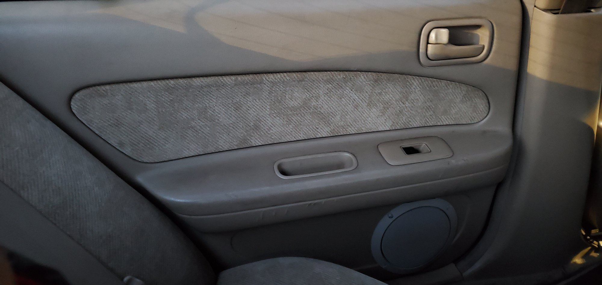
So that was the rear. Today, I completed the front. Similar process. Here is what I did for the driver’s side: 1) Remove the front door panel (thanks again pmohr)

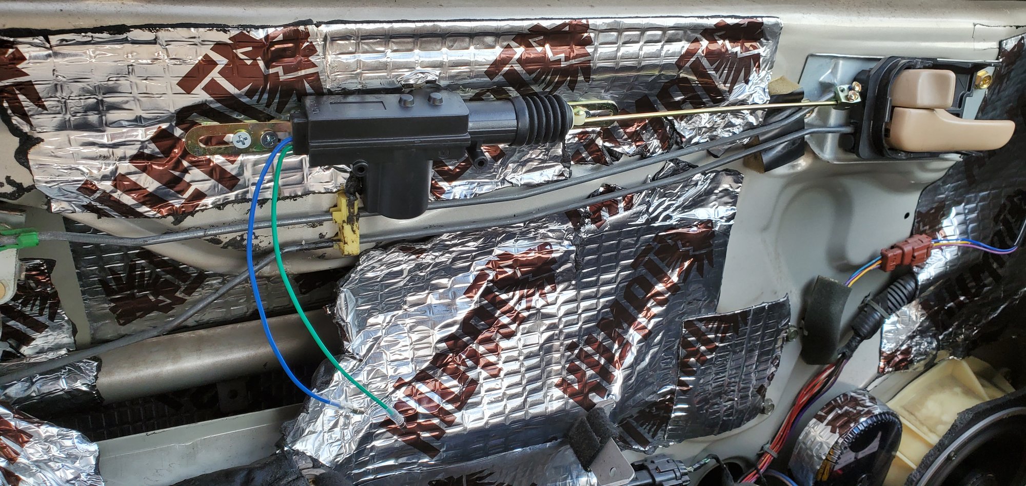
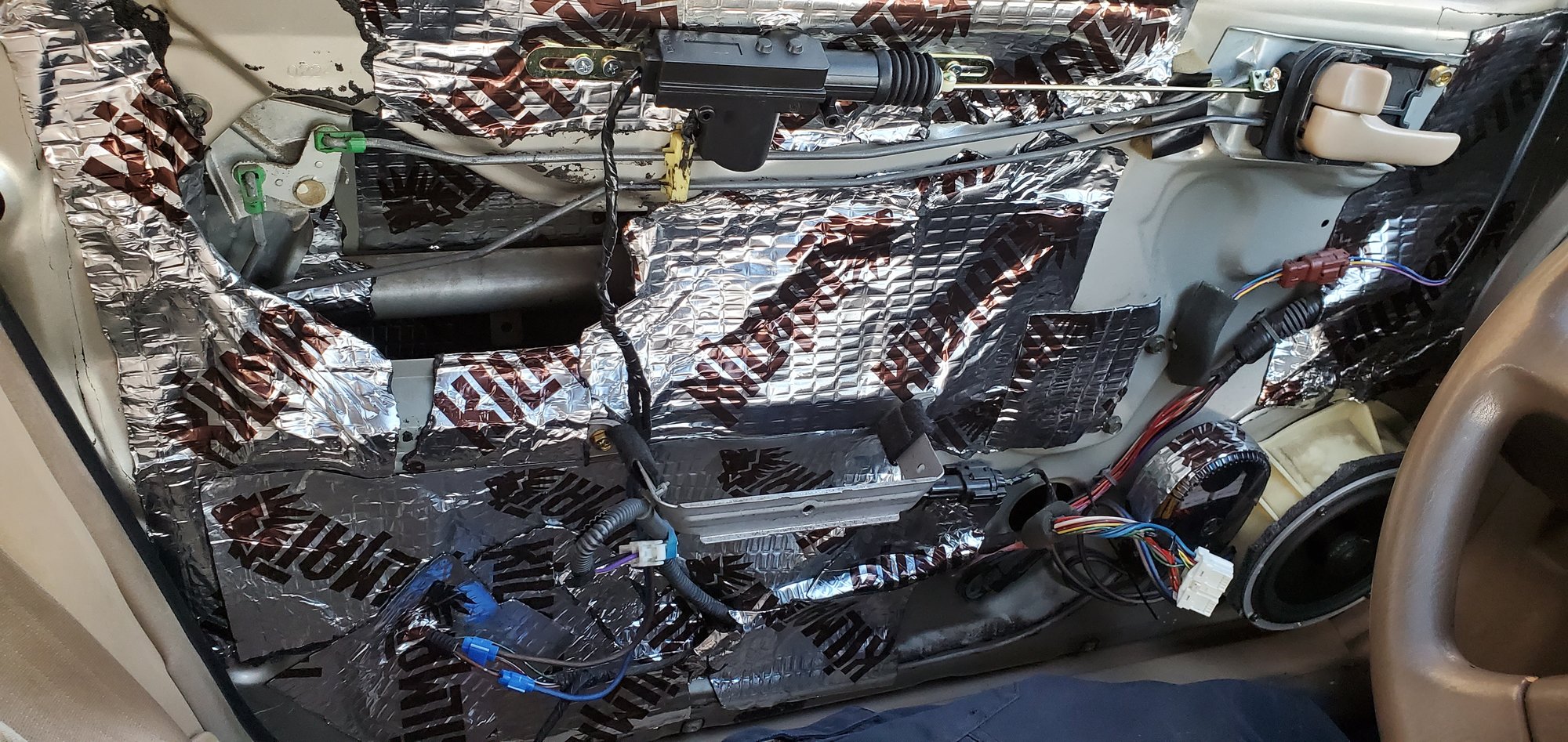
2) I chose this spot to mount the actuator. Before I screwed it in, I made sure that the panel would clip on properly without being obstructed by the actuator. It did, so there it went. Be sure to measure the new rod before you bolt it in place, because I had to clip off about 2 to 3″ of it for this application. Once I had the correct length, I fed the rod through the actuator, pushed the rod through the clamp, and then I snapped the clamp onto the factory rod. Applied some loctite and screwed it down. Of course, I managed to lose one of the screws. There are supposed to be two screws securing the new clamp to the factory rod, and one screw securing the clamp to the new rod. It held fine with one screw, so I proceeded.

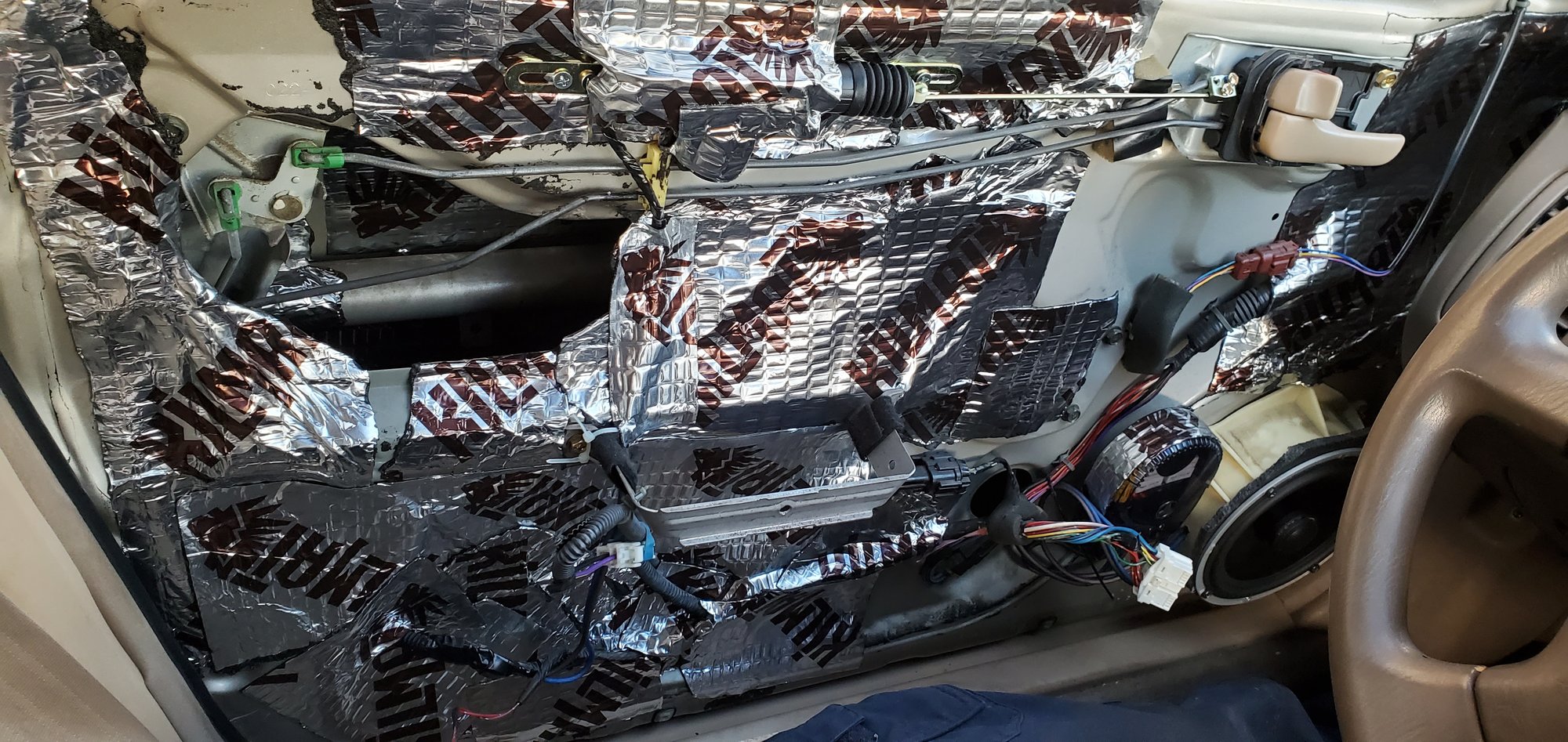
3) I already had some sound dampening material on my front doors, so I had to peel some of it back to access the wiring harness for the front actuator. It runs along the bottom of the door. I pulled it inside of my kilmat, and stripped away some of the plastic conduit to expose the wires. Same deal here as the rear, you want the brown / white and solid brown wires. Since the new actuator is at the top, and the wiring is at the bottom, I had to extend the wires. I crimped on some 14ga cable, wrapped it up, and ran it down to the factory harness. Used the blue wire taps again, wiring done!

4) Tested the new actuator, works perfectly! The lock snaps open and closed as if it were brand new. Video attached:

https://vimeo.com/user104171777

5) Wrapped everything up with tape, put some kilmat over the new actuator to help protect it (probably not necessary, but didn’t hurt anything).

6) Once I confirmed everything was working correctly, I put the door panel back on. It snapped right back into place. No resistance or snags of any kind. Well guys, the verdict is that these actuators are a definite hit for $13. I mean, that comes out to about $3.25 per door. So if anyone out there is in a similar position, I definitely recommend giving this a shot if you’d rather not drop about $500 on replacement bolt-on actuators. I hope that this thread can be helpful to some. Hopefully I didn’t leave anything out. If anyone has any questions, feel free to ask.

Loading