Tools needed
-10mm socket or wrench
-12mm socket AND wrench
-14mm socket or wrench (only if you have a FSTB)
-needle nose pliers and/or pliers
-patience and finger strength for the clamps/harnesses
1.) First you have to remove the engine cover.
2.) If you have a FSTB, then you will have to remove both strut covers and the strut bar itself. 14mm socket or wrench will be needed to remove the FSTB
3.) Now you may as well start with the more difficult part…in the rear of the manifold-this will be the left side…or passenger side.
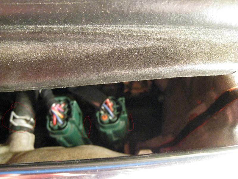
-Use needle nose pliers to slide the clamp off the hose and pull it off.
-Make sure to un-clip those two green connectors from their BRACKETS, do not just un-clip the female/male connection because it will still be connected to the bracket and will piss you off when it comes time to take the manifold off
-There is also a 12mm nut below and to the right of those harnesses’ that you will have to squeeze your hand into and be careful to not drop your wrench. It is holding on some bronze bracket.
4.) Now you will need to take your VIAS off if you have a grounding kit…if you do not have a grounding kit, then you will not have to take the VIAS off until you have the manifold off and choose to put a block off plate on it. Either way you should use a 12mm wrench here. And just carefully yank that thin black hose off.
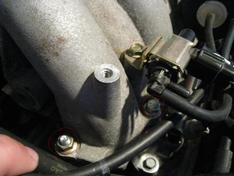
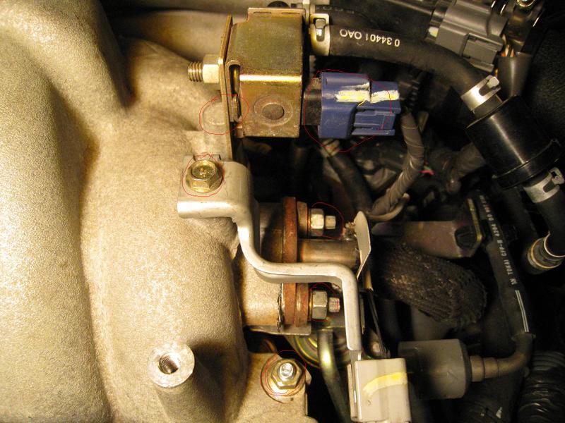
5.) Now you will take off the little bracket on the manifold with a 10mm socket and then 2/5 12mm nuts holding the manifold down.
6.) Now take the bigger bracket off the manifold which is held on by a 12mm bolt, so a socket or wrench would do good here, and a 12mm socket for removing 2/5 bolts holding the manifold.
7.) Now you have the last 12mm nut holding down the manifold on the bottom. Then take off both brackets with a 10mm socket and un-clip the blue harness. The EGR valve has 2 12mm nuts IIRC, so remove both of those and make sure to also take off the two washers that are on each stud so that they don’t fall into the engine bay while sliding it off.
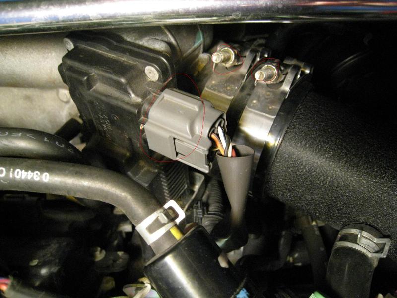
8.) Un-clip the throttle body harness and loosen your CAI hose.
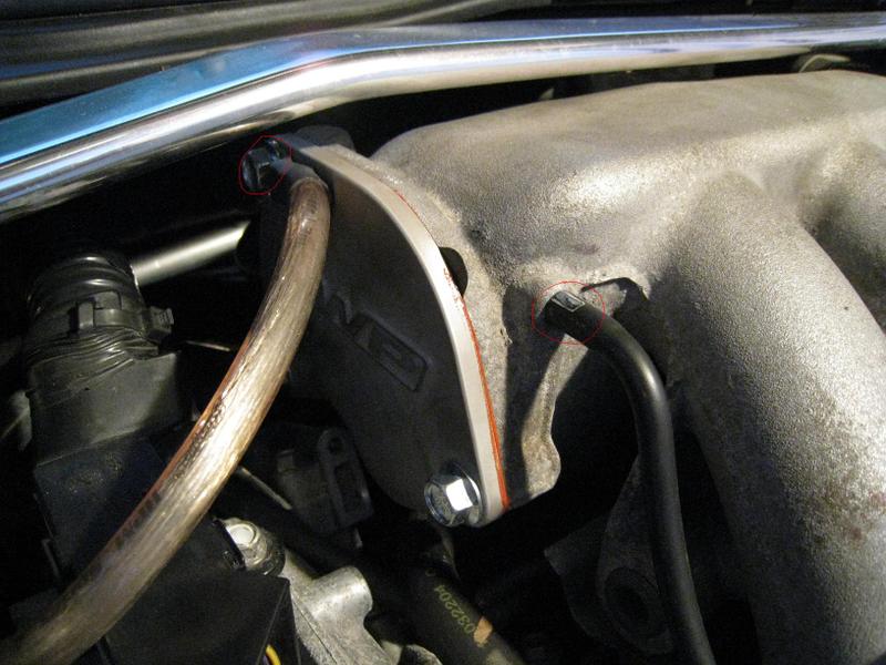
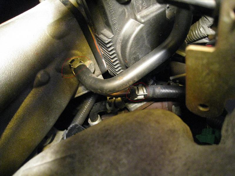
9.) Use needle nose pliers to slide the clamps off these two hoses. The bottom hose will leak out coolant, so put a towel there or w/e you want.
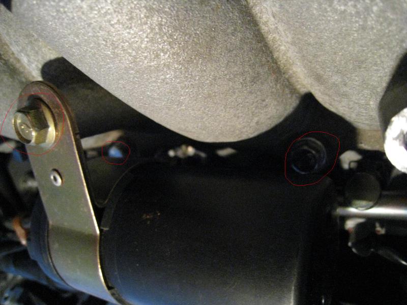
10.) If you do not already have intake manifold spacers, then you will have to remove the bottom two 12mm nuts off the elbow so that it will be off its bracket…BIGGEST PITA besides the driver side coolant hose. The bottom passenger side bolt isn’t that bad, but the bottom driver side is pretty damn tight, but doable with a 12mm ratcheting wrench.
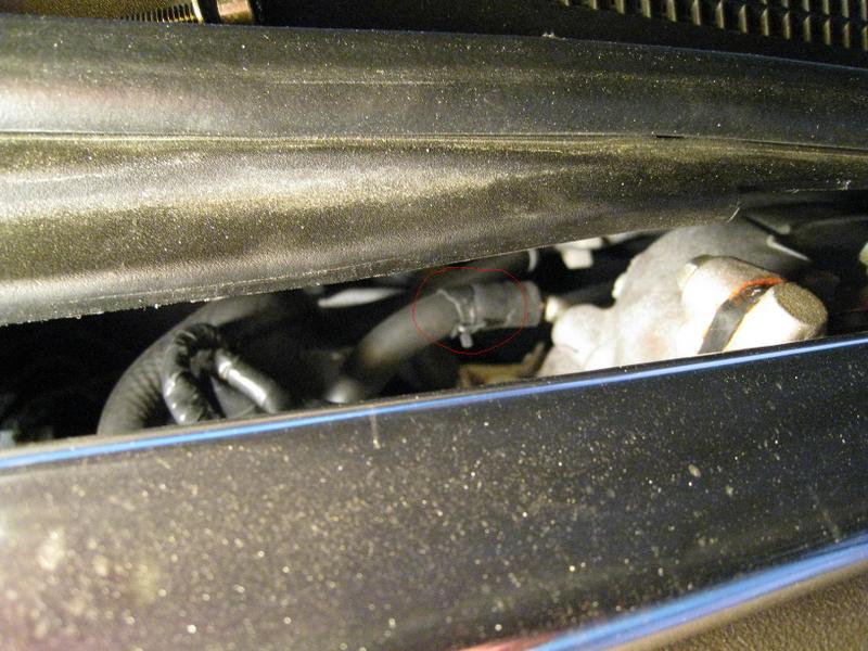
11.) Now you can start to slowly take the manifold off to get access to two more hoses in the rear. Lift the manifold and pull it to the passenger side so that the EGR valve can slide off because the thing is not too flexible. After you have the manifold off its studs and off the EGR valve, you should have enough room to get some pliers and take this hose off on the passenger side…
Notice how my clamp is NOT tightening the hose down too much because when I was putting everything back I did not realize that spacer would be minimal and did not feel like taking everything back off. Air blows out of that valve, so it shouldn’t be a problem and it hasn’t moved for the few days I’ve had it on…so hopefully it’s ok
Now the most PITA hose…behind the driver side on the elbow. This hose will also squirt some coolant out as well.
12.) When installing everything make sure that gaskets are in working condition and use some silicone gasket, which is what I used. I was going to use Permatex Grey, but my Nissan tech hooked me up with the stuff that they use, which is a tube of orange/redish silicone gasket that runs about $50 a tube
13.) When re-installing, make sure that you install those two difficult hoses first and then put everything back
Lift the front end of the car about two feet, high enough for you to get underneath and have
easy access. I used ramps. Please make sure car is lifted safely so there’s no serious injuries.
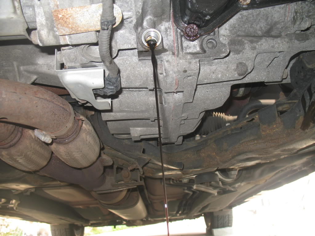
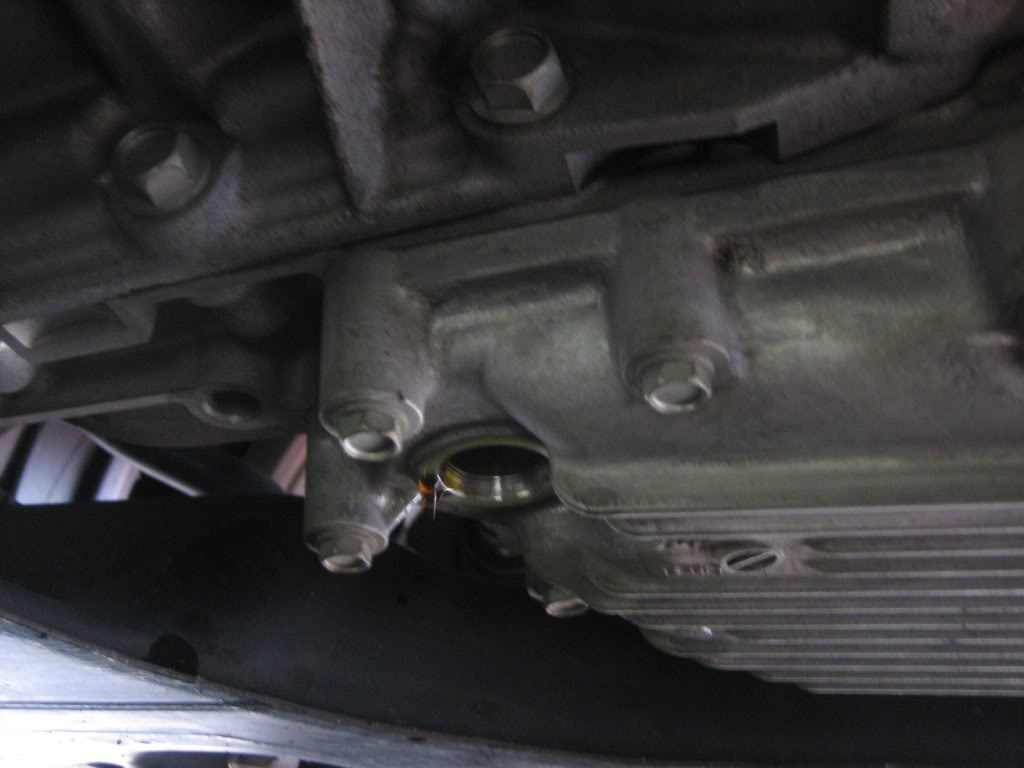
Drain oil from transmission, use an Allen key to remove plug.
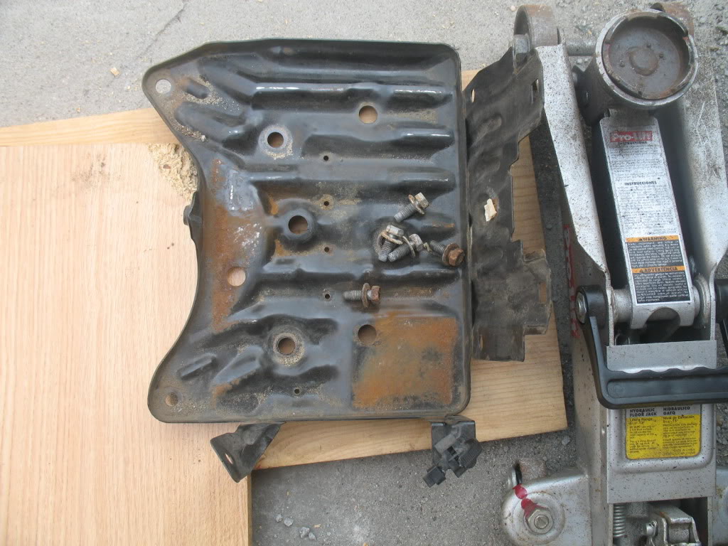
Remove battery & battery plate. You will be able to see the upper bolts.
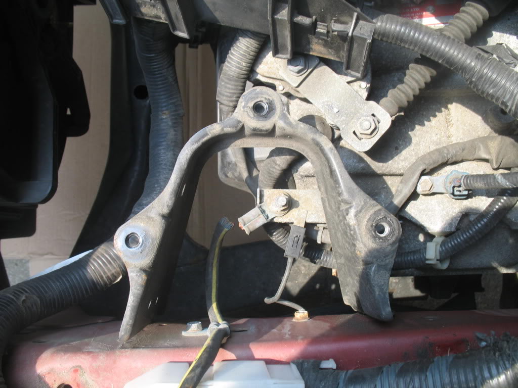
Also remove this bracket.
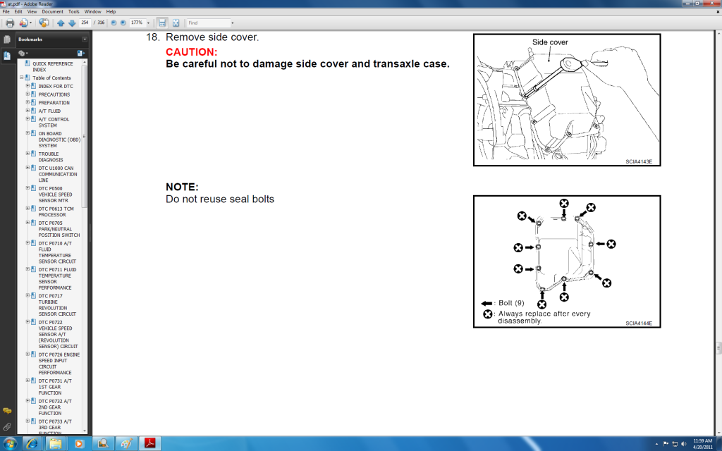
Now you are ready to start unbolting cover, but first spray Torx bolts with WD40, wait a few minutes before loosen them. The manual tells you not to reuse them, well let me tell you they cost $8 each at Nissan, I reused them. I cleaned them up with wire brush and break fluid cleaner.
Tip: A couple of the bottom ones were a little more worn from the weather, so when reinstalling put them on top.
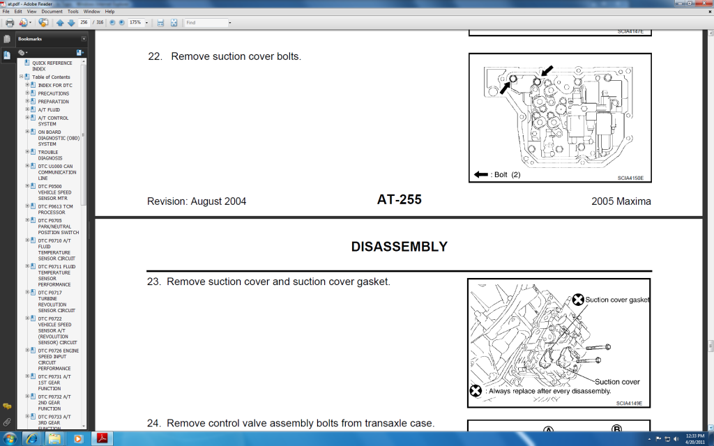
From the picture below remove suction cover bolts first. (this cover has a gasket that’s very brittle, it will most likely brake if you try to handle it. Tip have a new one on hand when reinstalling).
I strongly recommend having a second person working with you, one can be underneath the car and the other on top. I had more then one person working with me so we chose to unbolt first then to disconnect wires, if you are by yourself then I would recommend disconnecting before unbolting them just like on the service manual.
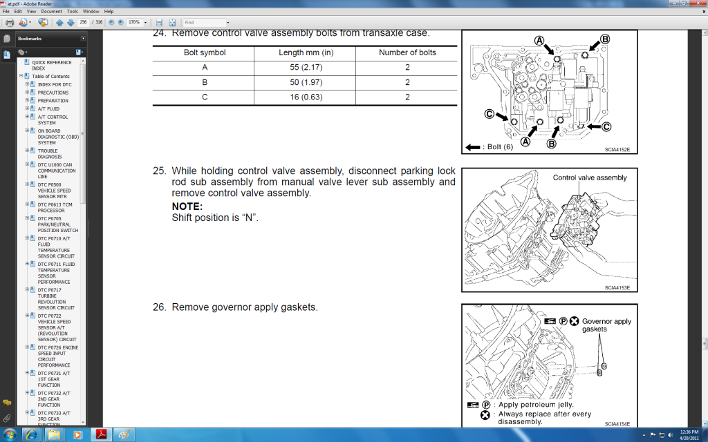
From underneath take out bottom and center bolts first, then from the top take out upper bolts, be sure to hold on to valve. You will notice they are not to tight, remember this when reinstalling not to over tighten them, if you have a torque wrench better for you. I didn’t have one so i just used same pressure to tighten them.
Once you pull the valve out, two small washers will either fall off or stay behind. from my photo one fell right away and the other eventually fell off also. these two washers were in excellent condition, so i reused them. In order for these two washers to stay up use Vaseline when you reinstalling new valve body.
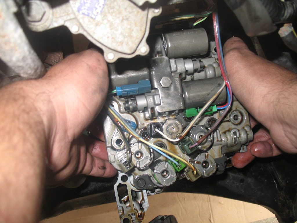
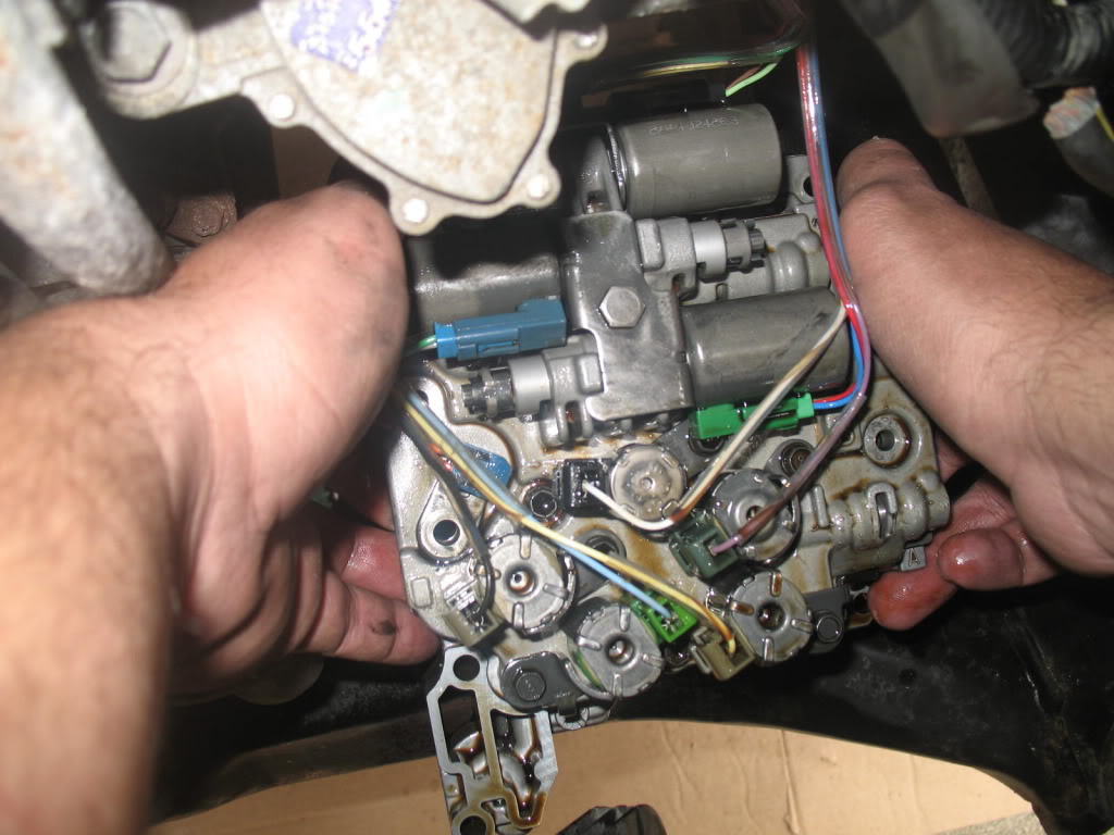
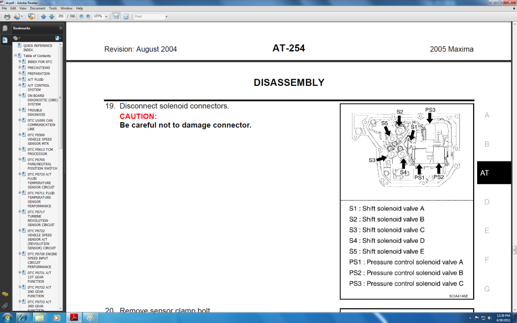
Here you will start to disconnect all the wires from the solenoids, the S1 – S5 were easy to disconnect, but the PS1 – PS3 were a pain to disconnect.
All the connectors are color coded and measure to length. when you reconnect them it’s hard to make a mistake.
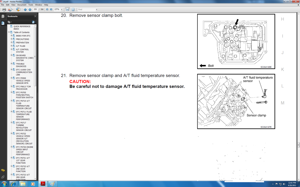
Remove bolt from sensor.
Installing new valve:
Place two washers with a bit of Vaseline on them back first, then while holding control valve assembly, connect the parking lock rod sub assembly to manual valve lever sub assembly. Then make sure you put the right bolts were they belong (what I did was, as I took one out I placed them on a towel picturing the valve, this made it easy to reinstall in order). Don’t over tight them, remember how they felt when you took them out.
Connect all the wires, again they are color coded and measured to length, but be careful. Make sure they are all connected.
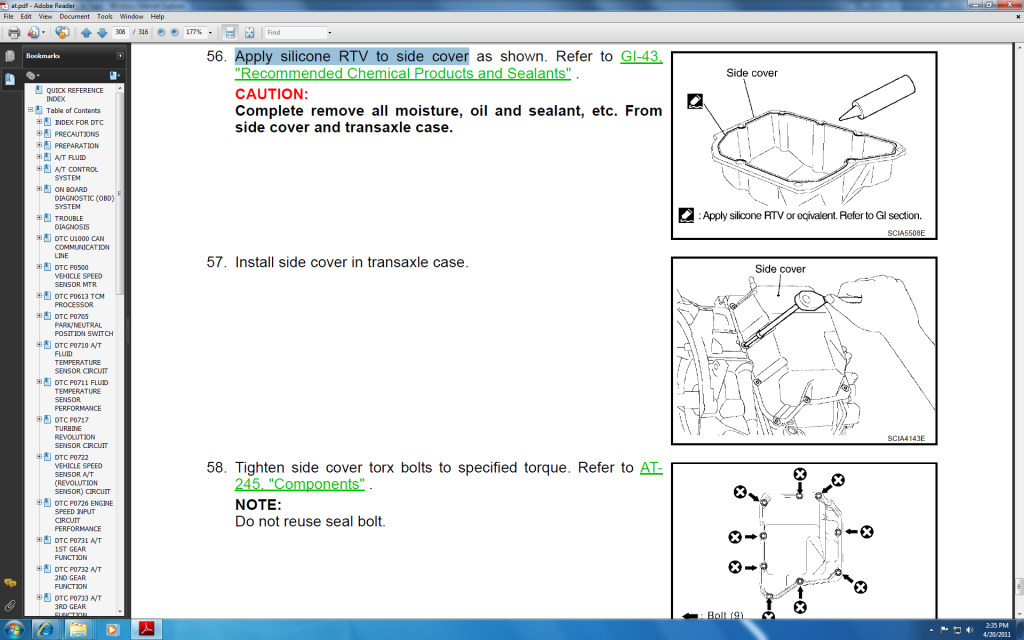
Follow these instructions to put cover back.
Wait an 1 hr for RTV silicone to cure before putting new oil. I lost 3 1/2 qts of matic k oil, so i replaced 3 1/2 qts of new Matic k oil. check for leaks, tighten accordingly.
WARNING: It is not recommended that you attempt this procedure without basic mechanical skills and knowledge of automobiles. Always take safety precautions seriously when working around an automobile. A simple mistake may cause you physical harm and/or death. Improper installation may cause mechanical damage to the vehicle.
Materials needed:
o Remanufactured Valve Body
o Permatex Ultra Black RTV Silicone Gasket Maker
o 4 Qts Recommended Transmission Fluid
o WD-40
o Torque Wrench
o Ratchet
o Extensions
o Metric Socket Set
o Phillips Screwdriver
o Pocket Size Flat Head Screwdriver
o Regular Flat Head Screwdriver
o Needle Nose Pliers
o 10mm Hex Bit
o T-40 Torx Bit
o Digital Camera and/or Notepad
Always make sure you have a clean work environment with plenty of room to move around. A confined space is not recommended for this job.
We take no responsibility for damages done to yourself, others, or your vehicle.
INSTALL AT YOUR OWN RISK
For Top Access (Bottom and Side Access Also Required):
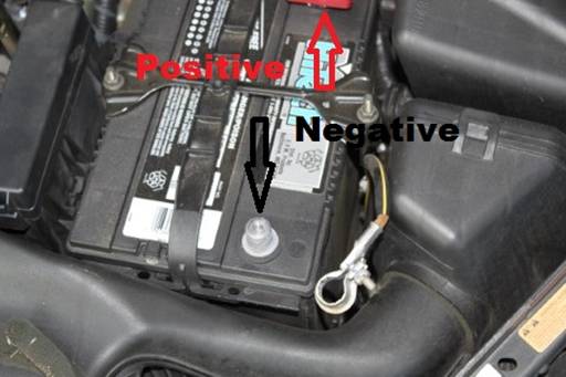
Remove the negative terminal from battery first, and then remove the positive terminal, both with 10mm socket.
Remove the battery clamp and battery.
Remove the fuse block on the left side of the battery plate.
Remove plastic battery tray to expose battery plate.
Remove 12mm bolts (5). Unclip wire harness from plate bracket. Use WD-40, if needed. Remove battery plate.
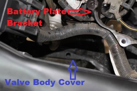
You will find a bracket underneath that supports the battery plate. Remove 12mm bolts (2) and bracket. You’ll need to unclip another wire harness. The valve body cover is just under this bracket and is painted black.
It is a good idea to hang the fuse block on the driver’s side of the car out of the way.
For Bottom and Side Access (Top Access Also Required):
Place the car on jack stands and remove the driver’s side front wheel.
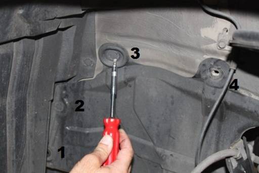
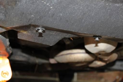
Remove theleft wheel splash guard by carefully pry the center of each clip and remove the entire clip. DO NOT PULL THE CENTER COMPLETELY OUT OF CLIPS.
You will be able to see the bottom of the valve body cover
Remove the engine splash guard (connected to bottom of front bumper and suspension cross member) by removing the clips on the rear of guard. Carefully pry the center of each clip and remove the entire clip. DO NOT PULL THE CENTER COMPLETELY OUT OF CLIPS.
Remove the 10mm screws supporting the front of the engine splash guard and lower guard.
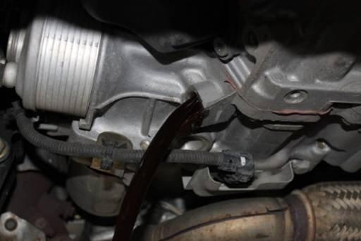
You should see the very bottom of the valve body cover and ATF cooler.
Remove Valve Body Cover:
Apply WD-40 to T-40 bolts (9) securing the valve body cover.
Drain transmission fluid using a 10mm hex driver into a large drain pan.
Expect 3.5 to 4 quarts of fluid to drain. Keep pan handy for valve body cover removal.
Remove T-40 bolts (9) from valve body cover. THE BOLT NEXT TO ATF COOLER IS DIFFICULT TO ACCESS!
Place drain pan underneath valve body cover. Carefully pry around edges of cover until the seal is broken. Expect fluid to escape from behind valve body cover. Remove cover, exposing the valve body assembly.
Remove Valve Body:
Important: It is a good idea to write down or photograph the connector positions and colors. In this example you will see that the rebuilt valve body has different colored connectors.
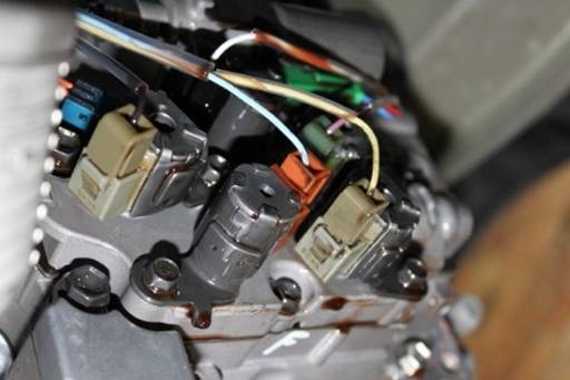
Begin by disconnecting the 5 lower solenoids using a small flathead screwdriver to push in the tab near the base of each while lightly pulling the connector out.
Remove the 10mm bolt and sensor retainer.
This is the retainer. After removing the bolt, it will slide off the sensor. DO NOT LOSE THIS RETAINER.
Carefully pull the sensor straight out of the valve body. An o-ring will be attached. DO NOT DAMAGE THIS SENSOR OR O-RING.
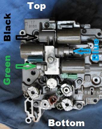
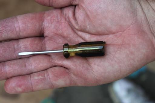
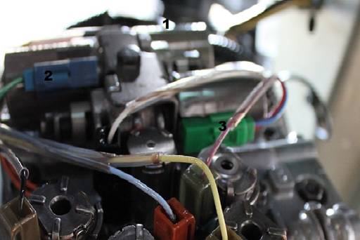
Disconnect the top three solenoids using a small flathead screwdriver. A pocket clip type flathead is too long to remove the middle of the three solenoids. In this case, the handle was cut to reduce the overall length.
The top solenoids are difficult to remove. DO NOT BREAK TABS ON CONNECTORS. Begin by inserting the screwdriver into the connector as shown with light force. Pivot the handle of the screwdriver outward while allowing the tip to dig in and pull the connector out. GO SLOW AND BE CAREFUL. This solenoid was removed from the valve body to demonstrate connector removal.
Here are the top three solenoid connector locations.
Carefully move the wire harness out of the way to prepare for valve body removal. Remove the remaining 10mm bolts in numerical order. Note that bolt 1 was removed with the sensor retainer. When removing bolt 7 be sure to catch the cover and gasket. They will be reused during installation. You will need to support the valve body while removing bolts 8 and 9.
Carefully pull the valve body away from the transmission and out through the top side of engine compartment. Pay careful attention to the manual valve, and control arm located at the very top of the valve body.
You have successfully removed your defective valve body.
Clean Valve Body Cover, Bolts and Transmission:
Now would be a good time to clean the valve body cover, bolts and mating surface on the transmission. Make sure all gasket material is removed and both surfaces are oil free and dry.
While cleaning the transmission surface, make sure that both o-rings are still inside transmission. DO NOT LOSE THESE O-RINGS. If they fall out, use a small amount of petroleum jelly to adhere them back inside transmission.
Preparing Replacement Valve Body:
Based on the car’s programming, your valve body may have a spring under the one of its valves. It is important to check for this spring’s existence and transfer to the new valve body, if required. If your valve body does not have a spring, check the new valve body for the presence of a spring and remove if required. MAKE SURE YOUR NEW VALVE BODY’S CONFIGURATION MATCHES THE OLD VALVE BODY. BE CAREFUL NOT TO DAMAGE COVER GASKET.
If valve pops up when cover and gasket are removed, a spring is present. IF VALVE APPEARS TO HAVE NO SPRING, MAKE SURE IT IS NOT STUCK.
Your replacement valve body will be shipped with the three upper solenoid/valve assemblies removed to prevent damage. They need to be installed into the replacement valve body.
Begin by removing the 10mm and 8mm bolts and brackets. The 8mm bolt secures a two piece bracket. The brackets keep the three solenoid/valve assemblies shown above in place.
Carefully insert the three solenoid/valve assemblies in the positions shown below. DO NOT INSTALL IN WRONG POSITION. EACH ASSEMBLY IS DIFFERENT. Install valve assembly brackets along with 10mm and 8mm bolts. DO NOT OVER-TIGHTEN. Your replacement valve body is ready to install.
Install Replacement Valve Body:
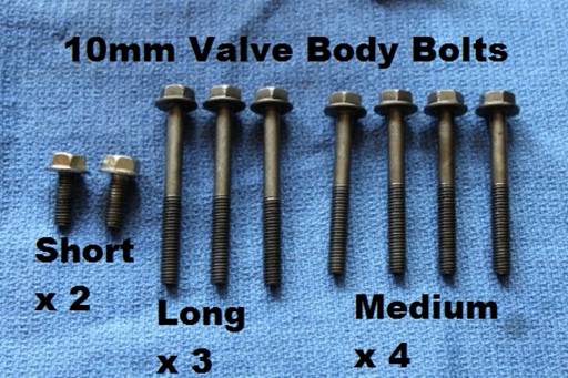
Take time to identify the valve body bolts. There are three types: 2 Short, 3 Long, and 4 Medium. All are 10mm.
Begin by inserting the top two bolts, labeled 1 and 2 in the picture below to hold the valve body in place. Carefully insert valve body into transmission, making sure it is lined up properly and seating onto o-rings. Pay careful attention to the manual valve, and control arm located at the very top of the valve body. The control arm must be reinserted into lever on transmission. The lever has been drawn to demonstrate proper positioning.
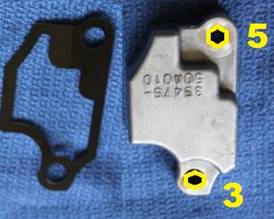
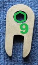
Hand-tighten bolts labeled 1 and 2 enough to secure valve body to transmission, and then install bolts 3 through 9 in numerical order. Be sure to reinstall cover and gasket under bolts 3 and 9. Before installing bolt 9, carefully insert sensor between bolt 7 and 9. Slide sensor bracket around sensor to hold in place, then install bolt. Lightly snug each bolt in numerical order with a ratchet, and then torque each bolt to 87 inch pounds, again in numerical order. PAY ATTTENTION TO BOLT LENGTHS AND POSITIONS.
Carefully reinstall all connectors to replacement valve body. DO NOT RELY ON CONNECTOR COLORS TO MATCH SOLENOID COLORS. Refer to your own documentation made while disassembling for connection. Start with the top three solenoids.
Next, reconnect the bottom five solenoids. Make sure the wires follow their natural shape and do not get crossed.
Take a few minutes to make sure that all wires are routed and connected properly. Your replacement valve body is now installed.
Install Valve Body Cover:
Make sure all mating surfaces and inside of valve body cover are clean, dry, and oil-free. Apply a small bead of RTV Silicon Gasket Maker to the mating surface of the valve body cover, making sure you surround each bolt hole.
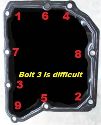
Immediately install valve body cover and hand tighten T-40 bolts (9). Follow RTV Gasket Maker’s instructions for best results. Torque T-40 bolts (9) to 10 foot pounds, in the order shown below. DO NOT OVERTIGHT T-40 BOLTS. Bolt 3 is difficult to install with a conventional ratchet and extension.
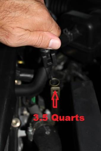
Wait at least one hour to allow time for RTV gasket maker to cure, and then add 3.5 quarts of transmission fluid designed for your car. THIS IS ONLY A STARTING POINT.
Check Fluid Level:
Reinstall battery plate bracket, battery plate, battery tray, fuse block, battery, and battery clamp. Make sure that all wire clips and harnesses are returned to their original positions as you work.
Reinstall the left wheel splash guard.
Reinstall the left wheel and lower car.
Connect the positive terminal to battery.
Connect the negative terminal to battery.
Warm up the engine.
Check for any transmission fluid leaks.
Before driving, the fluid level can be checked using the “COLD” range on the A/T fluid level gauge.
The car should be level, and parking brake set.
Move the transmission selector lever through each gear position, leaving the selector lever in the “P” park position.
Check the fluid level with the engine idling.
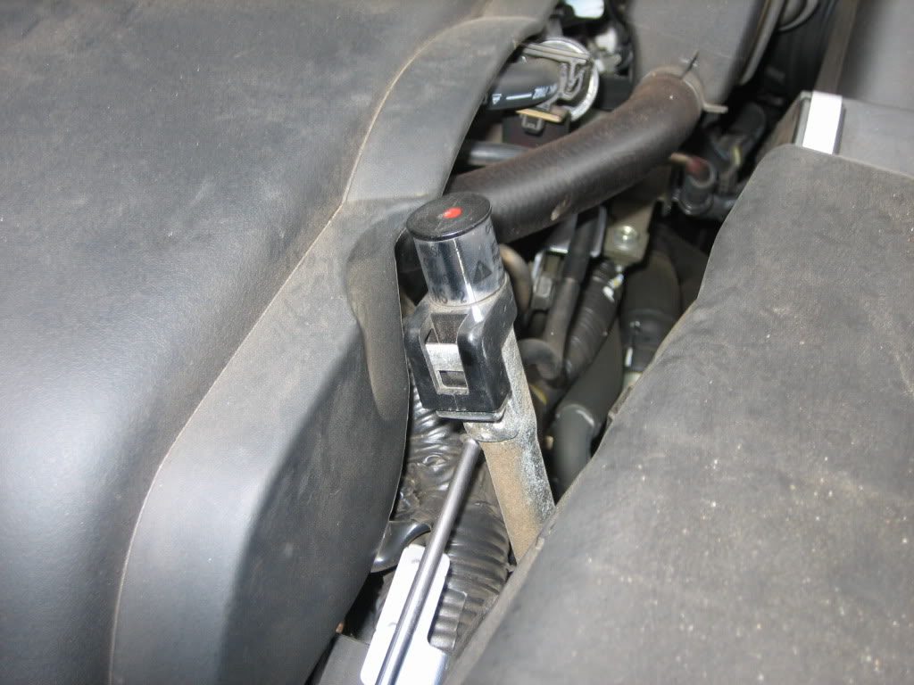
Remove the A/T fluid level gauge and wipe it clean with a lint-free paper.
Re-insert the A/T fluid level gauge into the charging pipe as far as it will go.
Remove the A/T fluid level gauge and note the reading. If the reading is at or below the low side of the range, add the necessary specified A/T fluid through the A/T fluid charging pipe.
DO NOT OVERFILL THE TRANSMISSION.
Retrain Your Computer:
Your car’s computer has adapted to your old, defective valve body, and must learn how to correctly shift again.
If no leaks were detected, reinstall the engine splash guard (connected to bottom of front bumper and suspension cross member).
Restart your car. Slowly move the shift lever through each position beginning with P all the way to D, and then back to P. Pause for a second or two in each position. Repeat this cycle several times.
Drive slowly to a spot where starting and stopping is safe. Make sure you have room for car to advance through all gears automatically and then come to a gentle stop.
While completely stopped, move shift lever to “D” position for automatic shifting. DO NOT USE THE TIPTRONIC (L/H) SHIFTER.
Gently accelerate until 5th gear is reached. You will need to listen and count as the transmission automatically changes gears.
When 5th is reached, stop accelerating and gently apply the brake until the car has downshiffted back to 1st gear and come to a complete stop.
DO NOT BE ALARMED IF THE CAR SHIFTS ERRATICALLY DURING THIS PROCESS.
Repeat this process five times. Shifting should be smoother with each pass.
Repeat this process five more times, this time more aggressively.
Your computer has been retrained.
Park vehicle and re-check the fluid level using the “HOT” range on the A/T fluid level gauge.
DO NOT OVERFILL THE TRANSMISSION.
Carefully pack your old valve body for shipment back to rebuilder. DO NOT SHIP WITH TOP THREE SOLENOID ASSEMBLIES INSTALLED. Pack them separately in the box with ample padding. Damage to old valve body will forfeit your core refund.
Congratulations! You have just installed a Maxima Valve Body.
Here is a high-level summary of the whole process:
1. Remove drain plug from CVT oil pan.
2. Drain fluid
3. Reinstall drain plug in oil pan
4. Fill CVT with tranny fluid at the charging pipe
5. Drive CVT for 10 min
6. Check fluid level.
7. Add fluid if necessary
Now on the actual procedure
Remember to only use OEM Nissan Fluid. Specs below:
CVT AUTO Type: NISSAN CVT Transmission Fluid Part #: 999MP-NS200P Price: $14.95/qt (You need approx. 6-7 quarts)
Tools/supplies Needed:
Pliers
10mm Allen Wrench, T-handle
1.5 ft. of clear flexible tubing (1 in. diameter)
Container marked of f at 1 qt. (did this with a measuring cup and sharpie marker)
Collection pan to collect the used transmission fluid
Flat Head Screwdriver
Transmission Fluid Funnel
6-7 Quarts of NISSAN Matic-D Automatic Transmission Fluid
Experience needed: I would say some experience working on cars, at least be able to do your own oil changes before you try to do this. You will also need one person around to help.
Step 1: Drive car around for about 10 minutes to warm everything up. Park it, run through all the gears (P, R, N, D, and then back to P) and leave the engine running. Pull the transmission dip stick out, wipe clean, insert back in but rotate 180 degrees and push all the way down. Pull back out and check the level (remember where it is so you can refill back to same location, should be at the second notch). This is also where you will add transmission fluid.
Step 2: Raise the front end of the vehicle somehow. I have small ramps I use for changing my oil so I drove up onto these. Turn off the car.
Step 3. With the dip stick pulled out. Place a collection pan underneath the transmission drain plug. Using the hex screwdriver/tool, unscrew the drain plug. Notice that it doesn’t take much force to unscrew this so don’t over tighten when putting back on. Allow all of the fluid to drain, I left it to drain for about 15 min.
Step 4. Screw the drain plug back on. I think you can replace the o-ring on the drain plug but I didn’t do this.
Step 5. Measure how much fluid you drained out by using your container that you marked off at 1 qt. I drain roughly 4.5 qts. Add the same amount of fluid you took out back into the transmission through the recharging pipe (same place you pulled the dip stick out) using your funnel.
Step 6. Lower the car down. Run it back through all the gears and check the fluid level just as before. Adjust the fluid as needed.
So I decided on something a little easier with the same result.
Just to remind everyone, this will make it:
PULL BACK = Next Gear PUSH FORWARD = Previous Gear
And the best part? It takes 15mins or less, uses $2 worth of connectors, and is totally reversible in a matter of seconds!
Tools Needed: – side cutters – pliers – 2*blade connectors – female – 2*blade connectors – male – electrical tape
Time Needed: 15mins
Picture 1:
Pull the centre part of your dash off using info on these forums
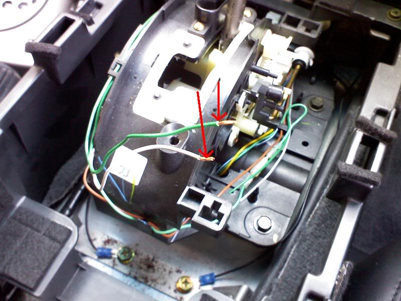
You will see a few wires which run around behind the gear selector and these are involved in the tiptronic switching
Locate the 2 wires which send the signal back to the ECU when the gear has been manually changed
The colors you are looking for are DARK GREEN and LIGHT GREY
Note that there is also a light green wire so don’t get confused
Picture 2:
Cut these 2 wires and strip all 4 free ends
Picture 3:
Attach the male and female ends of the blade connectors using the pliers to hold the wires in place. You could probably solder them if you could be bothered.
Picture 4:
Connect the wires
The key here is that you want to swap the wires around so that the grey is now connecting with the green for both wires
Note that as you have used blade connectors, it is very easy to simply pull out the connector and put the configuration back to normal if you ever want to!
Picture 5:
Using electrical tape, cover the exposed metal of the connectors and put the wires back into their normal position. You can hardly notice that anything is done! Put your trim back in place
Test Drive: Amazing, simply amazing. It’s stupid that it wasn’t this way to start with.
Summary:
This is a DIY that costs the price of a box of connectors and takes about 15mins to do. Not only that, but it is completely reversible in the event that you change your mind!
I’m going to get some custom stickers made up that have a ” + ” and ” – ” sign on them for completeness. They will be black like the P-R-N-D indicator on the other side of the shifter
1. Drain out oil and coolant. drain the coolant as much as possible because it will drip for a while after the majority is out.
2. Remove oil filter
3. Take a 22mm socket and break loose the nut/bolt (its a bolt with a hex on it) holding in the cooler. its best to get a de-greaser of some kind and wipe it dry so the socket doesn’t just slip. once you break it loose, keep loosening it and take out the nut/bolt
4. More oil will come out (not much more) and here is the MESSY part. there are two tubes coming out of the oil cooler. these tubes contain the remaining coolant that did not flush out from the radiator. once you remove these two tubes coolant will come out and a good amount of it so have your coolant container ready and try to aim the hose to the bucket, but it will be difficult. 9/10 times the coolant will mix with the oil and make the coolant unusable so have a fresh gallon of it ready.
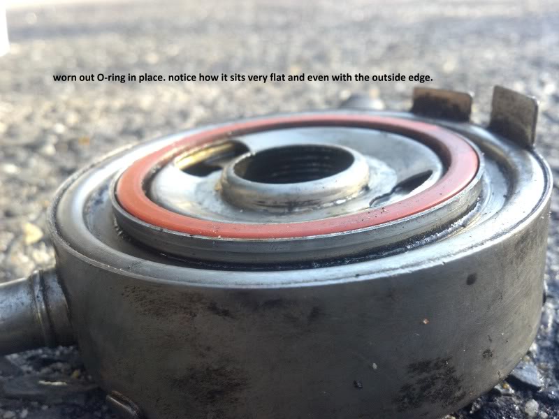
5. Once the cooler is out, the O-ring will be on the other side. mine was red and the new one from nissan is black. i dunno if thats normal or whatever. simply get the old ring out, place the new one, clean the cooler if you want and you’re done with this part. now reverse the install, fill the motor up with oil and put coolant in the radiator, tighten down every and double check on it and you just saved yourself a good deal of cash!!! lol
Oil cooler housing
Part number for new O-ring
And in case anyone wants to know, this is the oil/filter combo i personally use.
OK, I had been pumping more air (well I’m boosted) and wanted a better fuel balance so I talked with Tim at Speed Force Racing who makes the 6th Gen Turbo kit and he recommended installing the Walbro 255 fuel pump which I did yesterday. After install I noticed a high pitch noise which is not so noticeable inside since I sound proofed the back seat area and my trunk was already done previously. Anyway I spoke with Tim at SFR and Googled this Walbro noise problem and low and behold, it’s normal, so with that said, anyone upgrading their Fuel pump to a Walbro 255 should expect the same thing!!!
Walbro 255 Fuel Pump
Back seat removed prior to removal of fuel pump assemply
6th Gen Fuel pump assembly removed/new fuel pump installed
Under rear seat area sound proofing using B-Quiet Ultimate.
I am not an expert or a pro, I am not telling you this is the way it is done or has to be done.
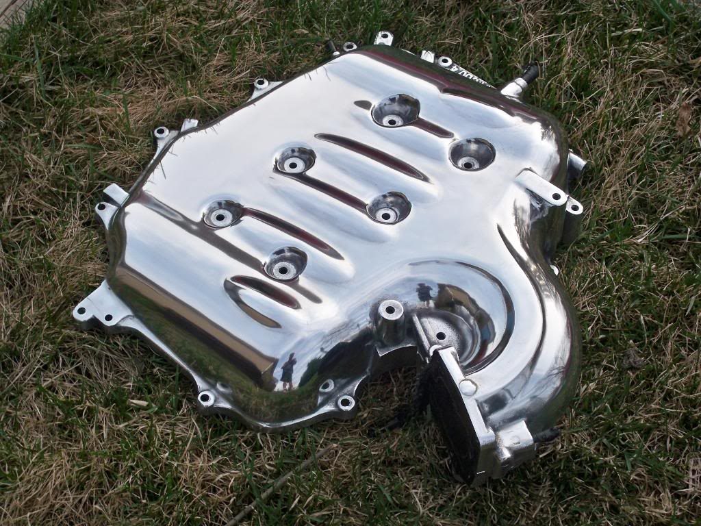
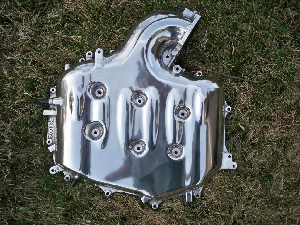
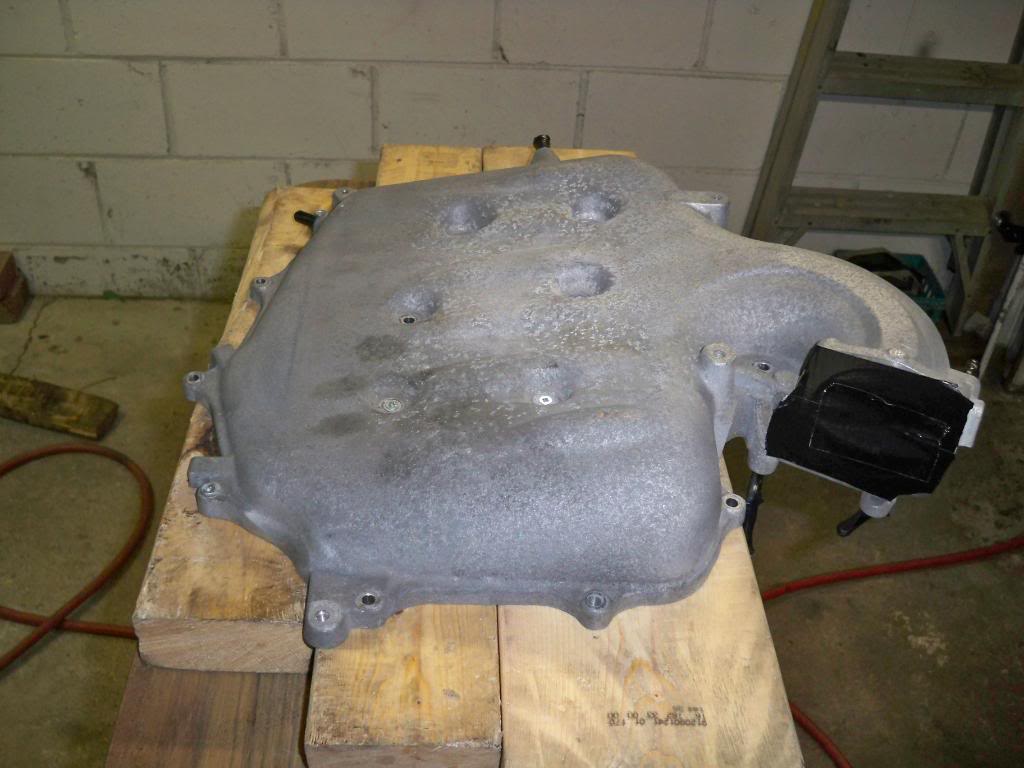
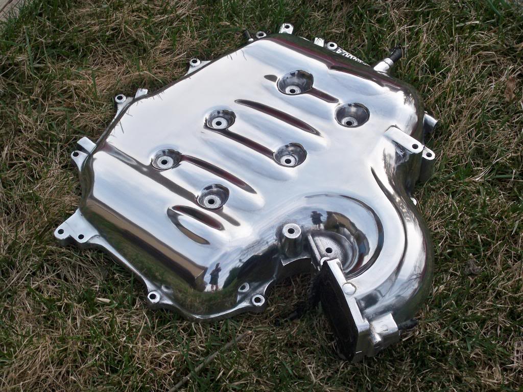
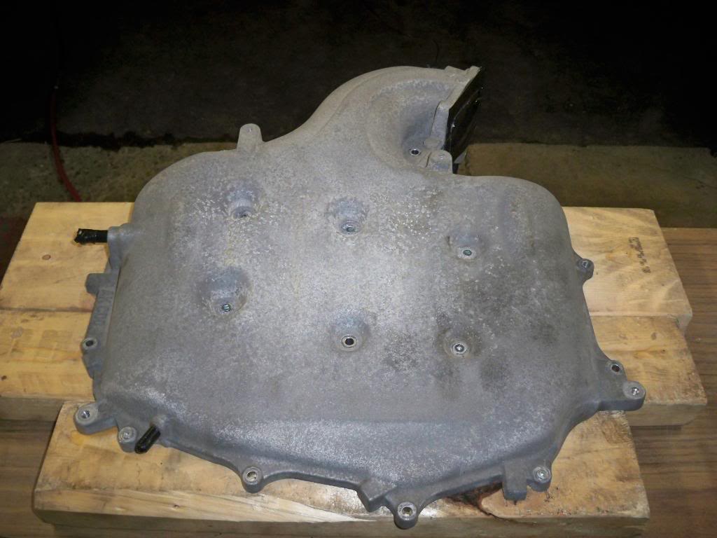
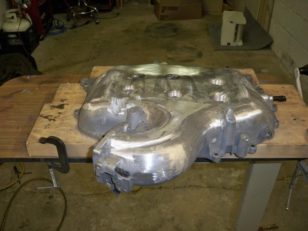
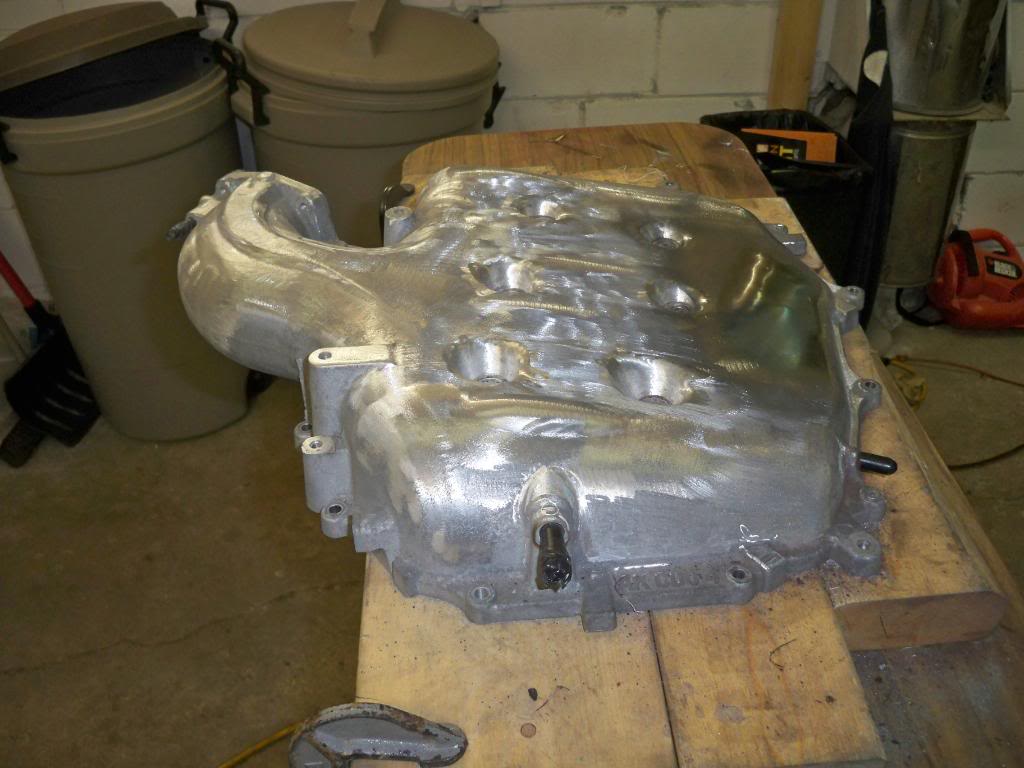
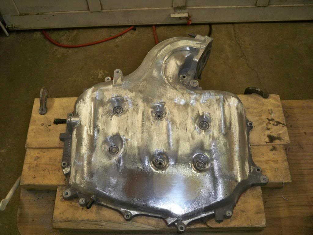
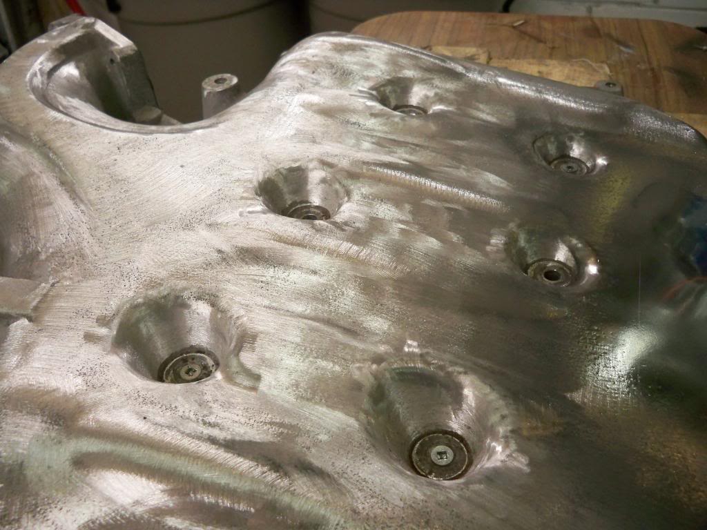
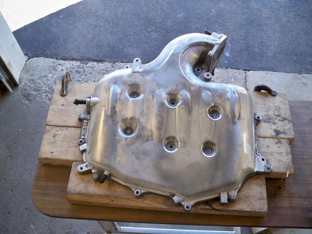
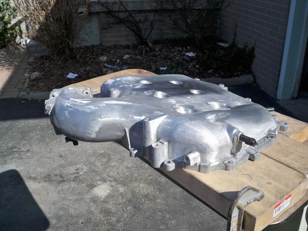
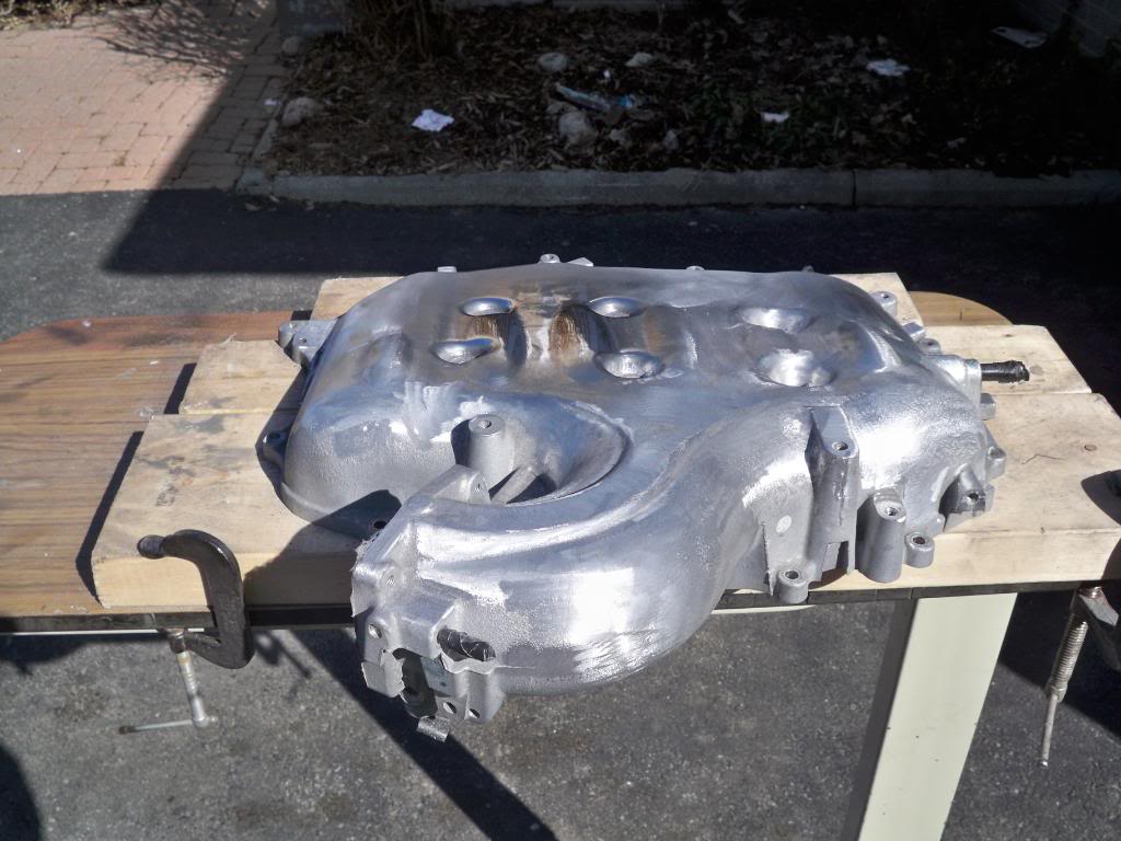
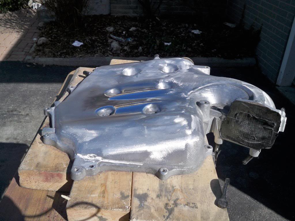
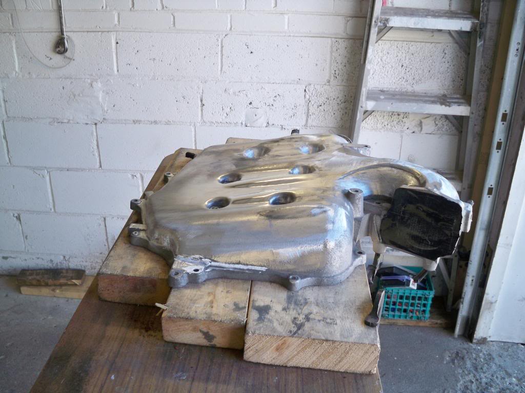
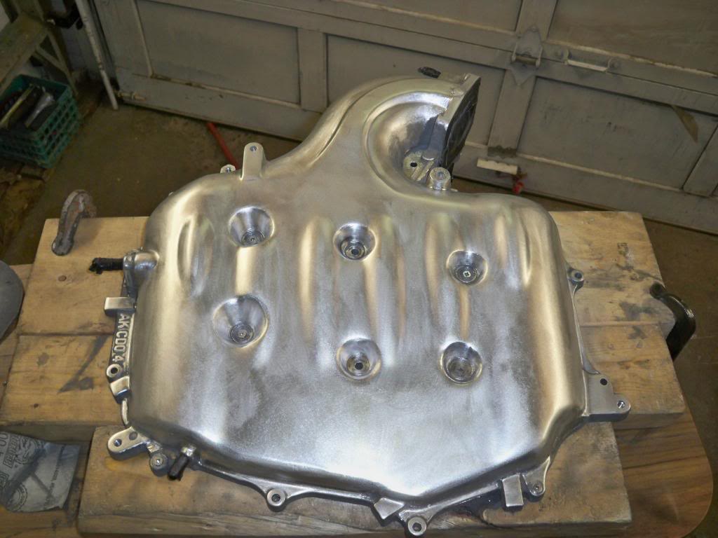
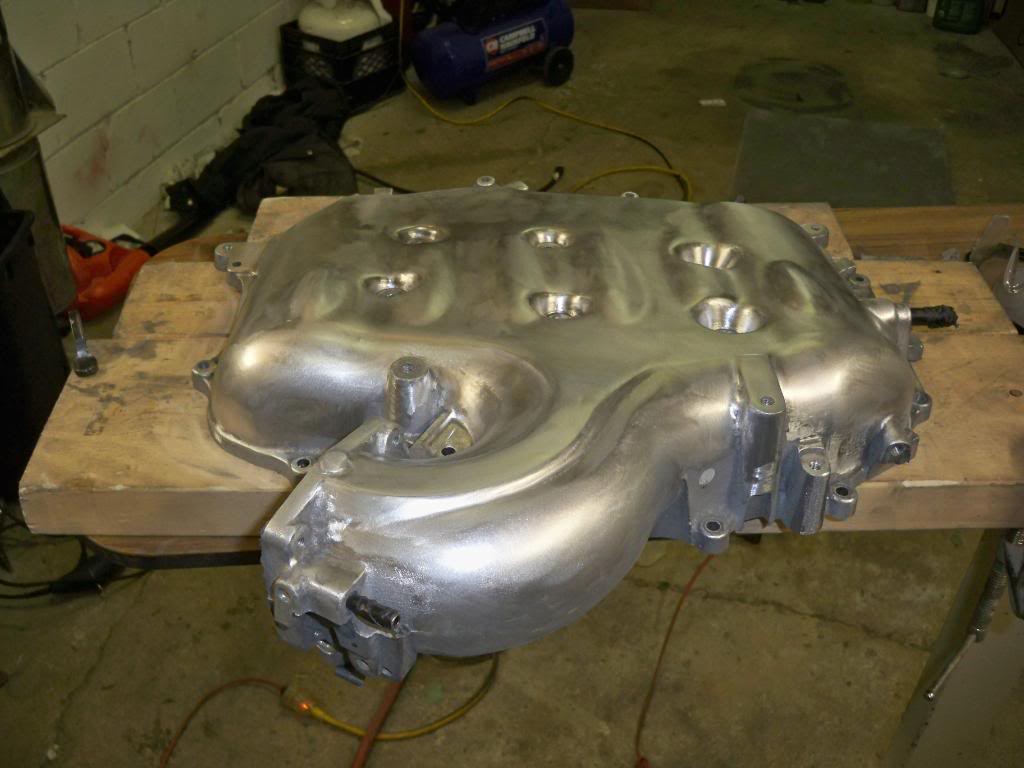
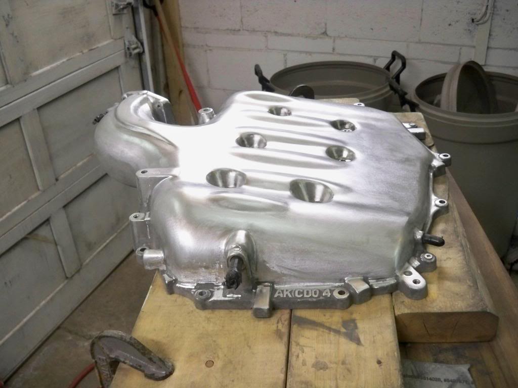
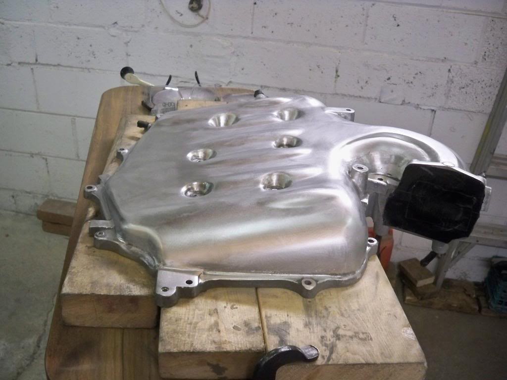
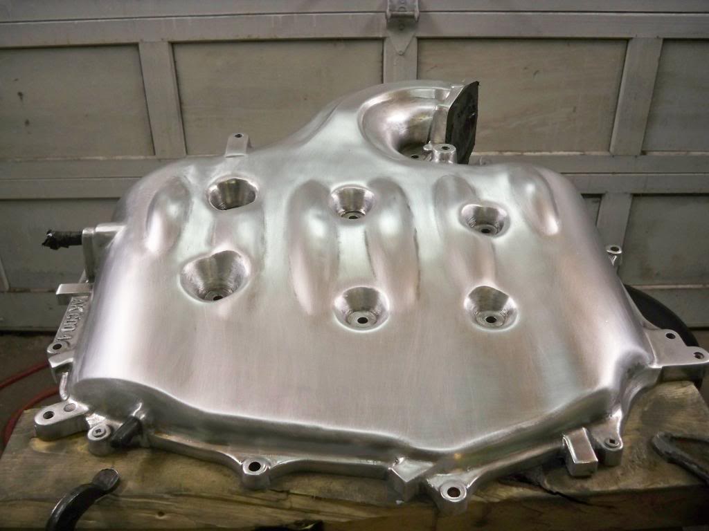
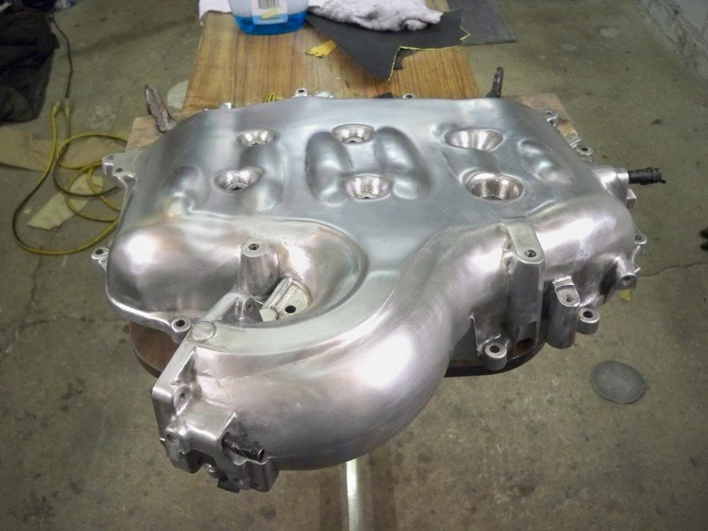
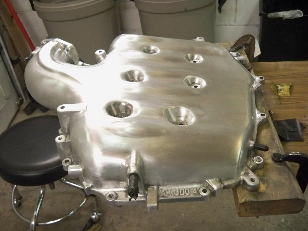
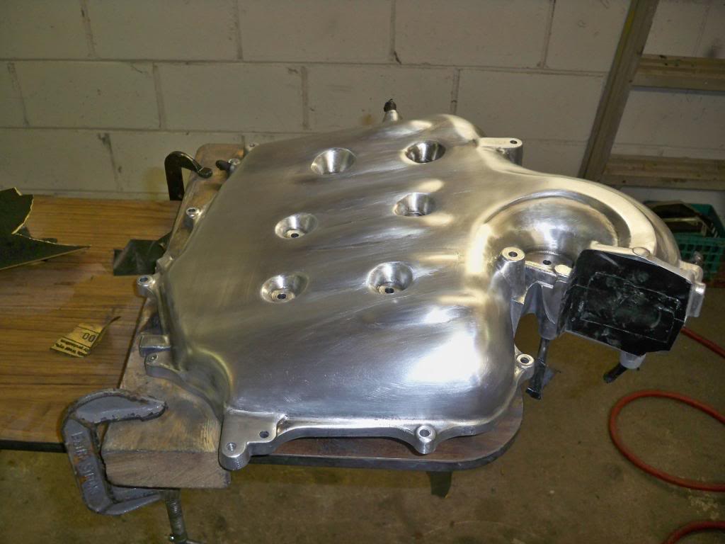
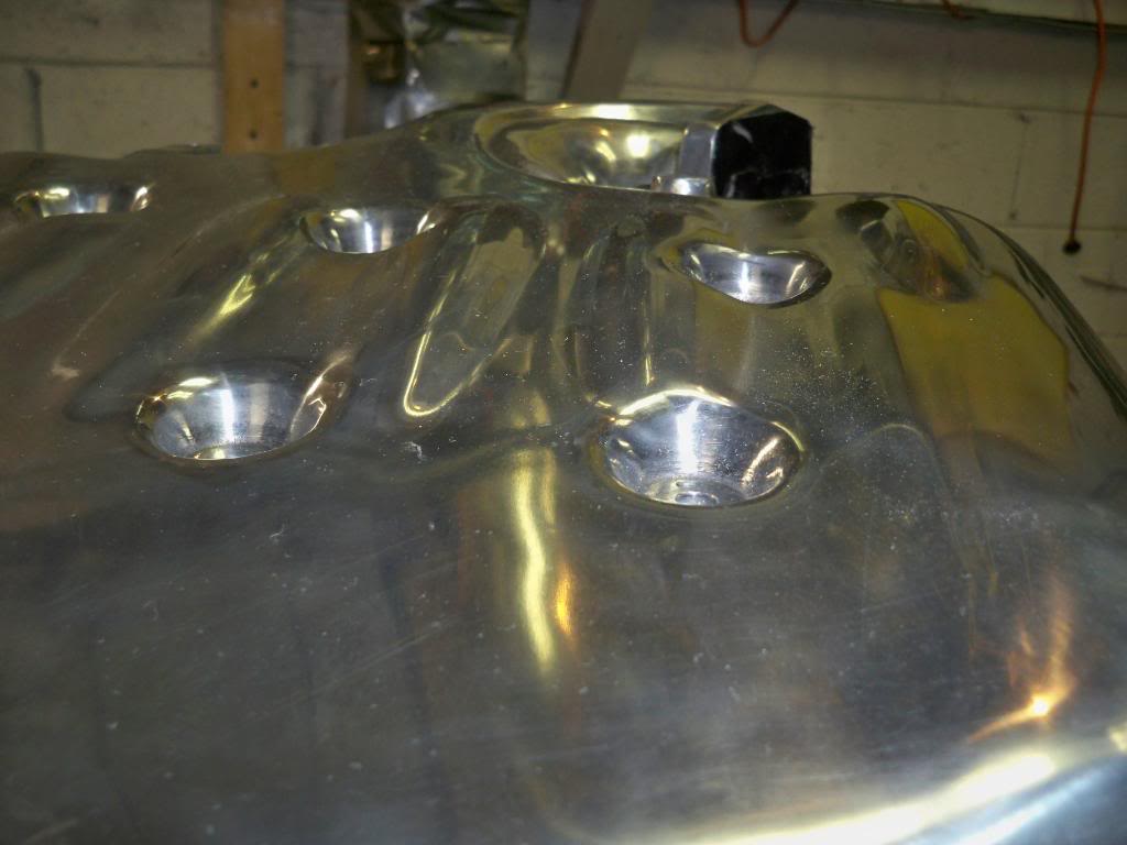
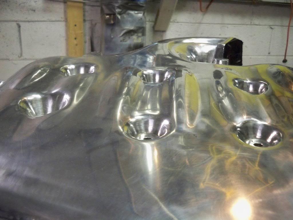
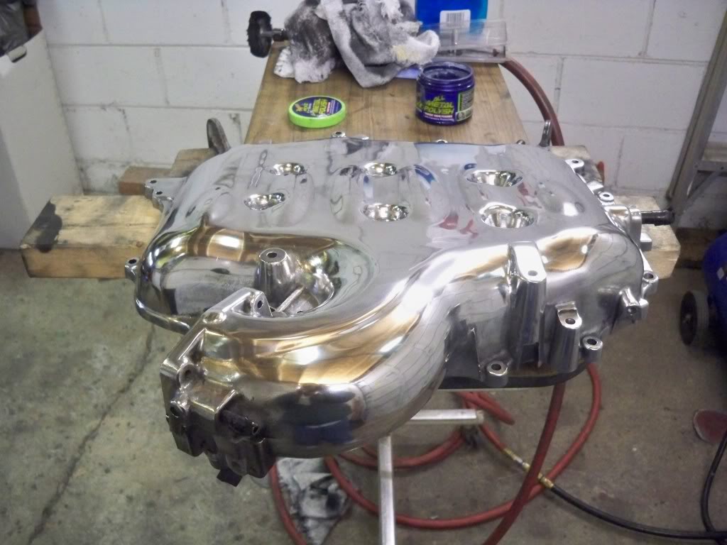
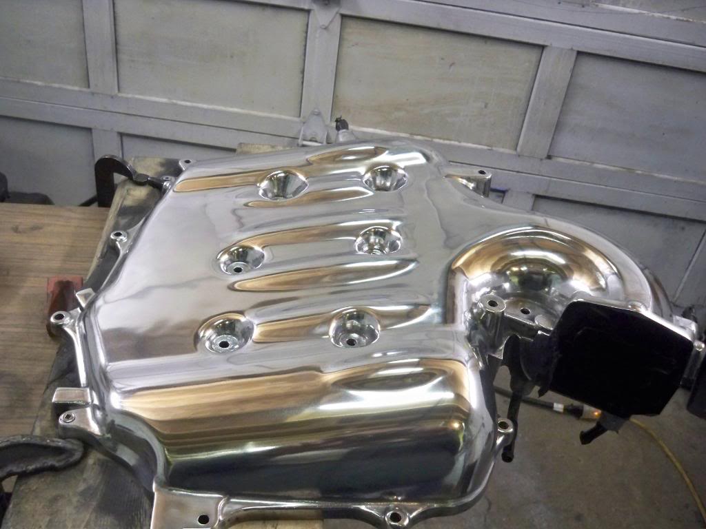
This is what I did and used to polish my plenum, I made this thread to help others.
If you know a better or faster way to do this by all means post how, we are all here just to help each other. This job took me 25 hours over 4-5 days. If I had done it over 2 days and had a larger compressor I think I could have done it in much less time, around 16 hours possibly.
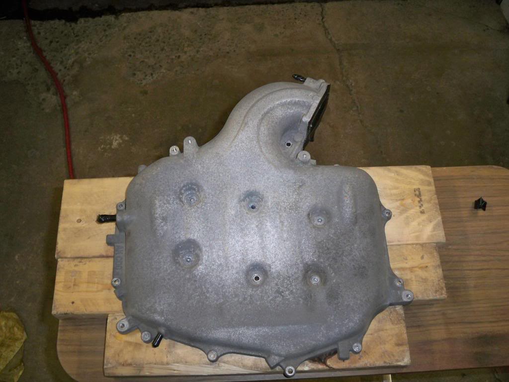
Before:
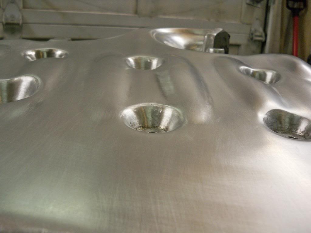
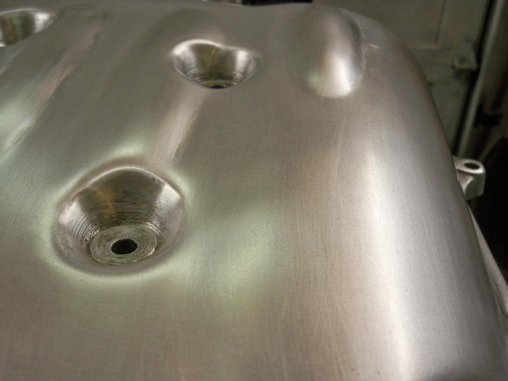
After:
Before:
After:
Before:
After:
I have seen a few zeds online here with a polished oem upper plenum and liked it so I decided to do mine. Some have done them themselves others have paid around $300 to get them done professionally.
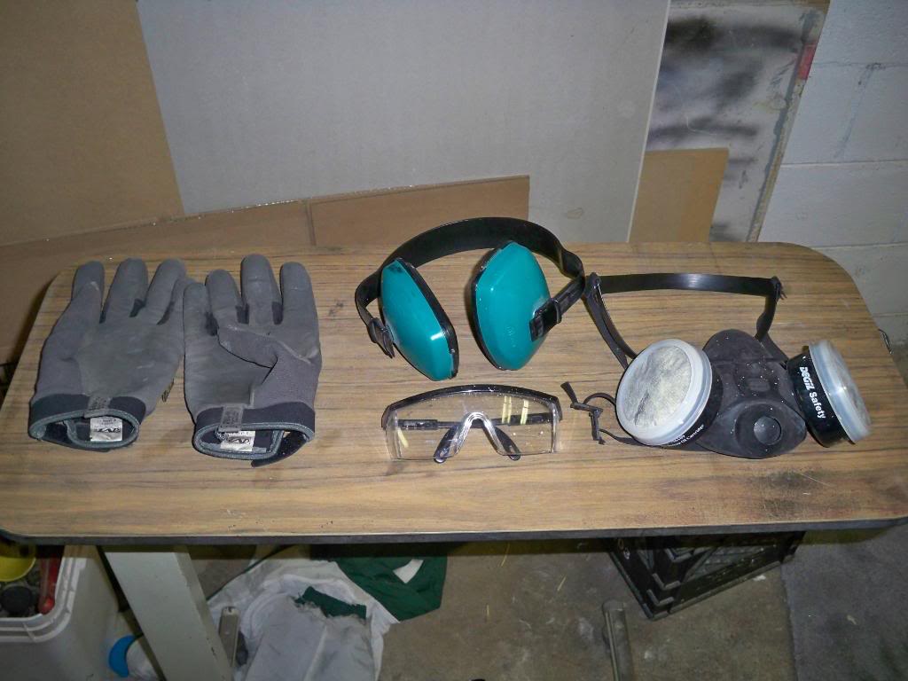
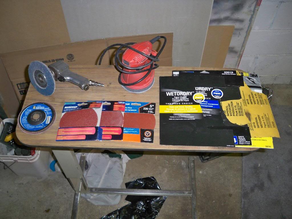
Here is some of the equipment I needed to complete this project
-Safety glasses
-respirator
-ear protection
-gloves
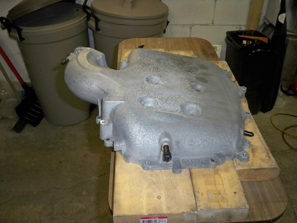
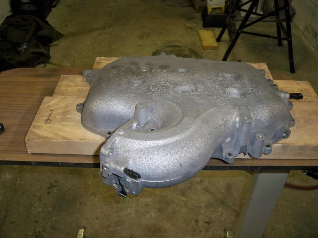
I bought an extra plenum to polish that way my car would still be drivable. What it looked like when I stared, rough and dirty.
After 4 hours of using an air grinder with a 40 grit flap disk and a Rotary tool with a grinding stone. (should have took less time but even with 2 compressors I still had to wait for them to keep up)
Here is some of the equipment I needed to complete this project
-Air grinder
-40 grit flap disk
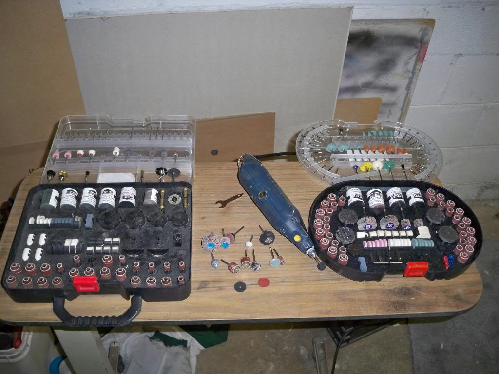
-Rotary tool with and assortment of grinding stones
On a small part of the plenum you can see I did a few more steps to see some shine, (I wanted some motivation lol)
After another 4 hours of using an air grinder with a 80 grit flap disk and a Rotary tool with a grinding stone and 80 grit flap wheel. (should have took less time but even with 2 compressors I still had to wait for them to keep up)
Here is some of the equipment I needed to complete this project
-Air grinder
-80 grit flap disk
-Rotary tool with and assortment of grinding stones, sanding wheels and flap wheels.
On a small part of the plenum you can see I did a few more steps to see some shine, (I wanted some motivation lol)
After another 6 hours of using an electric orbital sander with 80 grit sand paper, 120 grit sand paper and 220 grit sand paper. A Rotary tool with a 80 grit flap wheel and wire wheel. (should have took less time but even with 2 compressors I still had to wait for them to keep up)
Here is some of the equipment I needed to complete this project
-5 inch electric orbital sander
-80 grit sand paper
-120 grit sand paper
-220 grit sand paper
-Rotary tool with and assortment sanding wheels, flap wheels and wire wheels.
After another 3 hours of wet sanding by hand with 400 grit and 800 grit. A Rotary tool with a 80 grit flap wheel, wire wheel and sanding wheel.
Here is some of the equipment I needed to complete this project
-400 grit wet sand paper
-800 grit wet sand paper
-Rotary tool with and assortment sanding wheels, flap wheels and wire wheels.
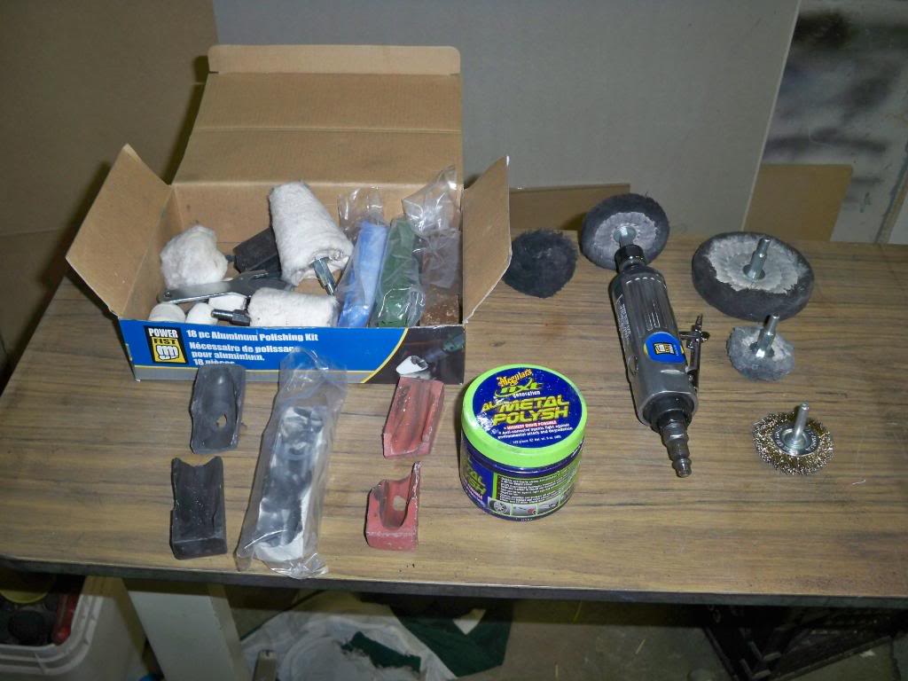
After another 2 hours of using an air die grinder with a felt/cloth wheel and a black compound/bar.
Here is some of the equipment I needed to complete this project
-Air grinder
-an assortment of felt/cloth wheels
-black compound/bar
After another 2 hours of using an air die grinder with a felt/cloth wheel and a White compound/bar.
After another 2 hours of using an air die grinder with a felt/cloth wheel and a Red compound/bar.
After another 2 hours of using an air die grinder with a felt/cloth wheel and Metal polish
— another 6 Hours total—
Here is some of the equipment I needed to complete this project
-Air grinder
-an assortment of felt/cloth wheels
-White compound/bar
-Red compound/bar
-Metal polish
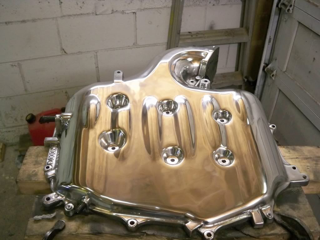
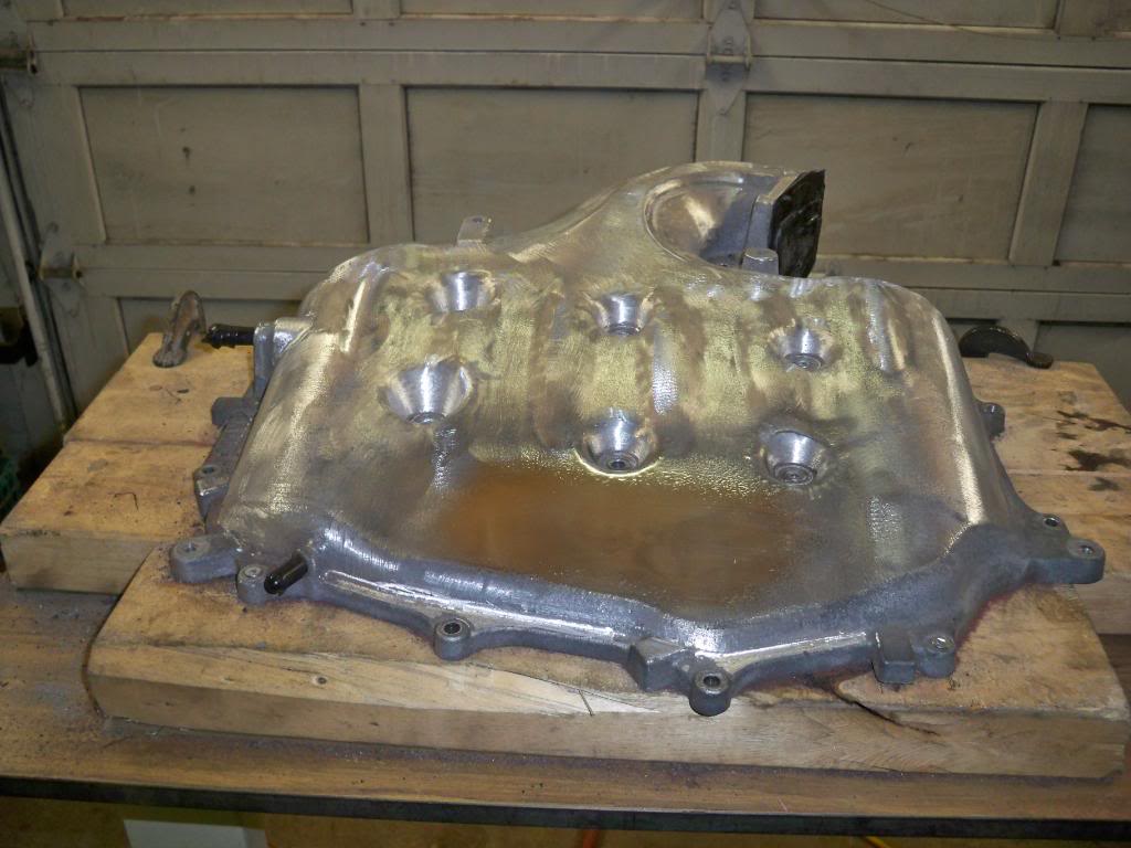
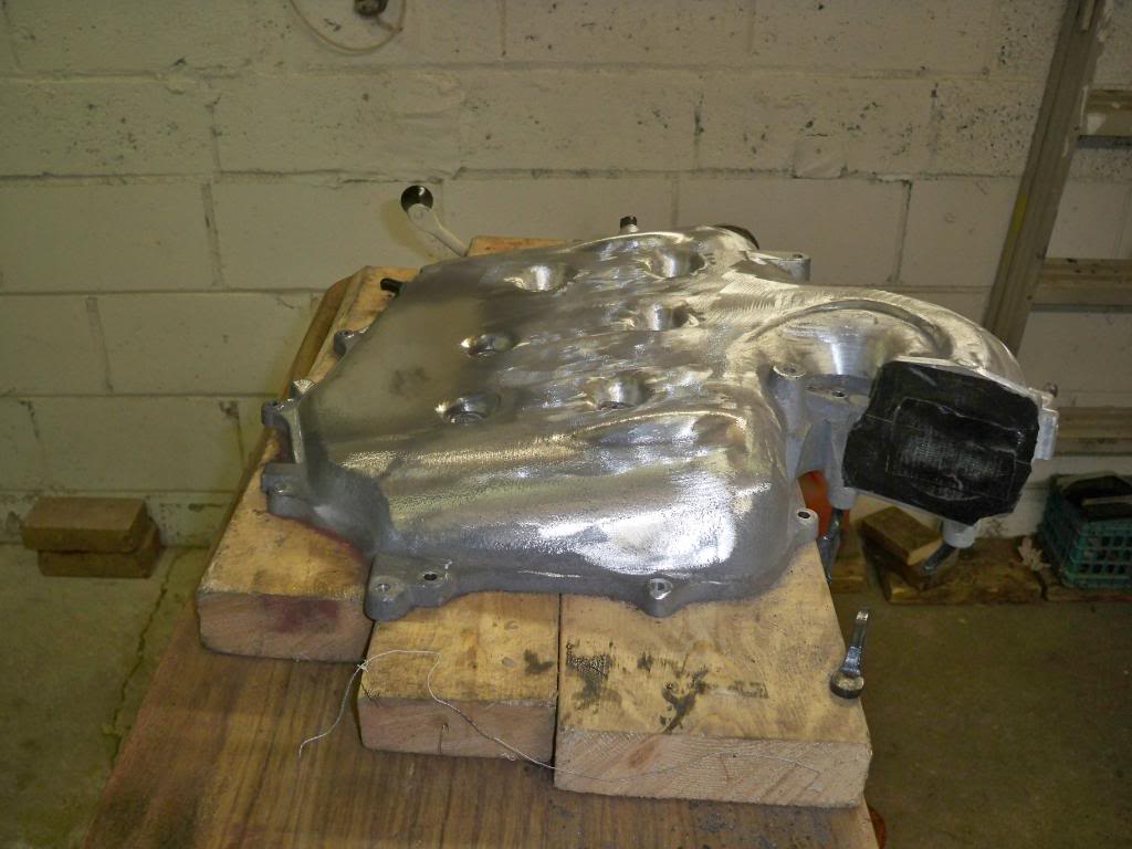
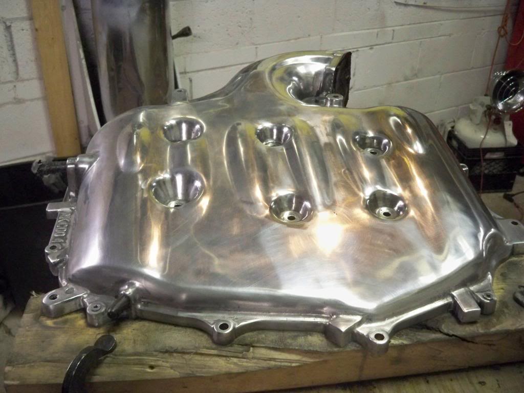
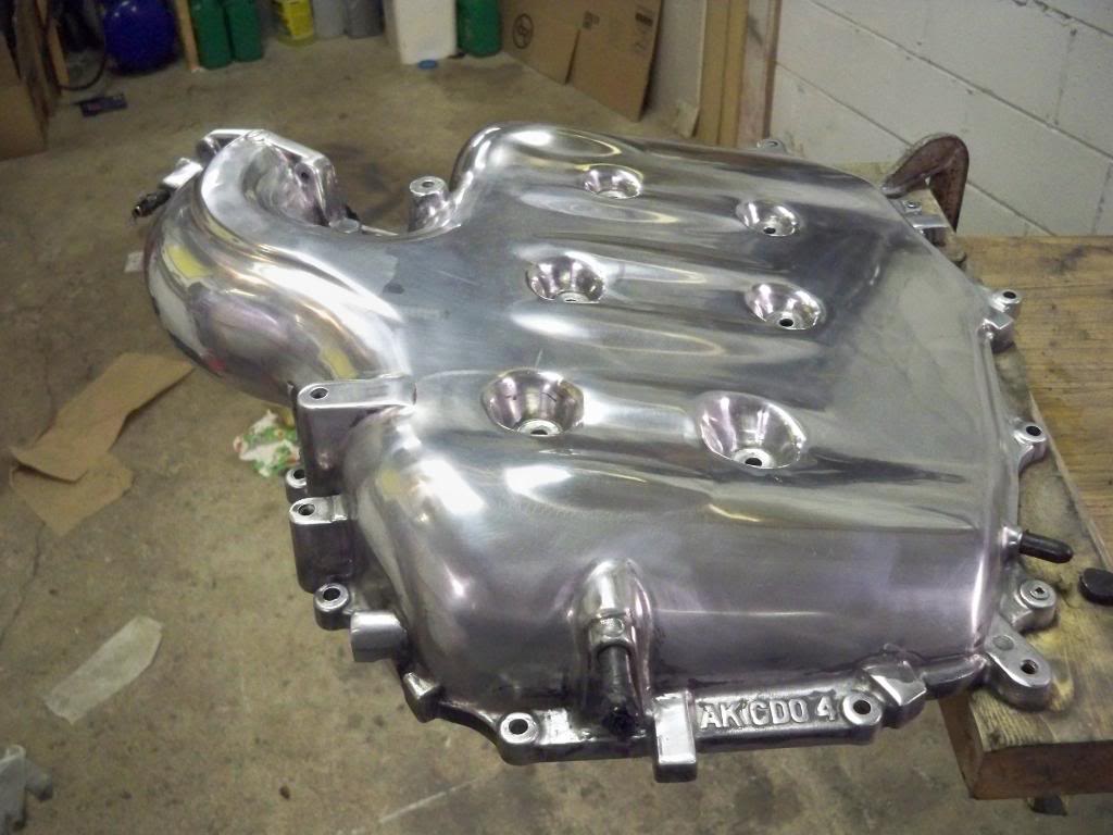
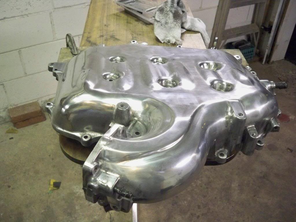
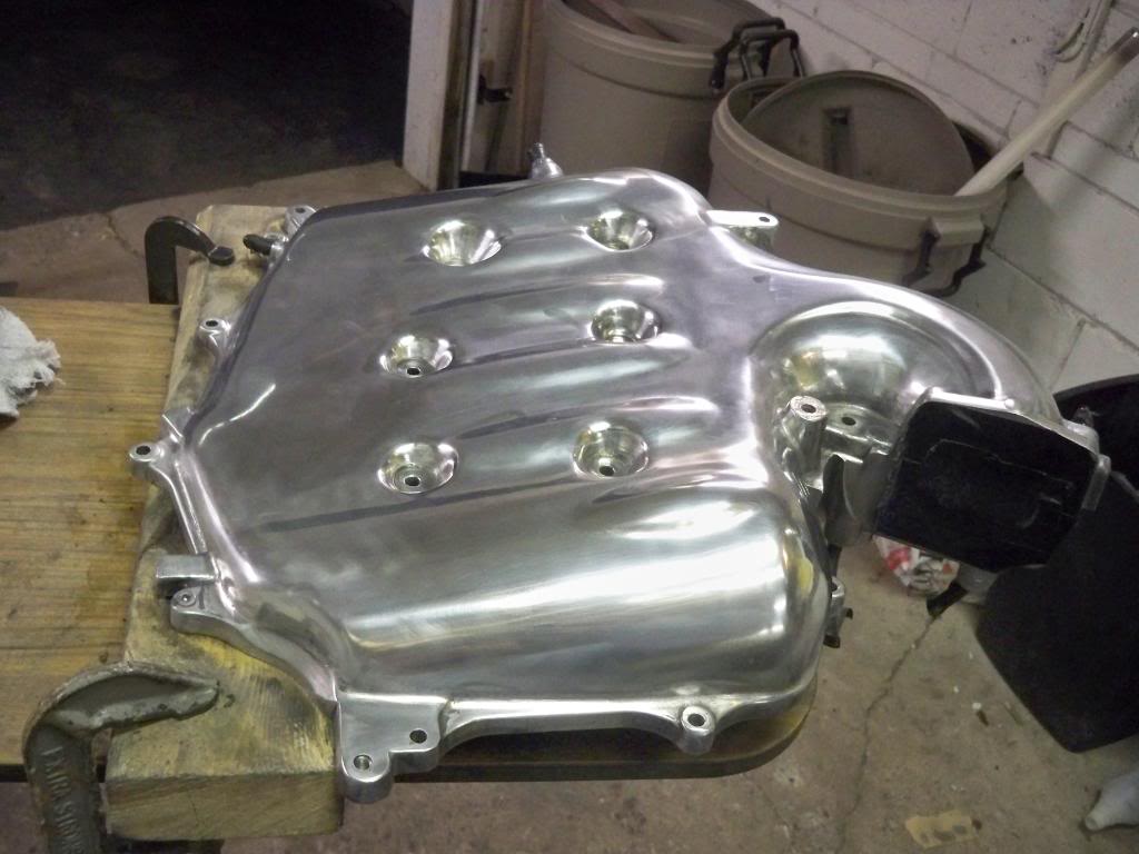
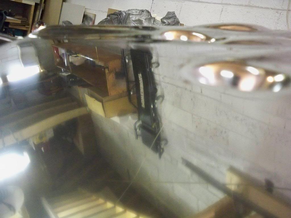
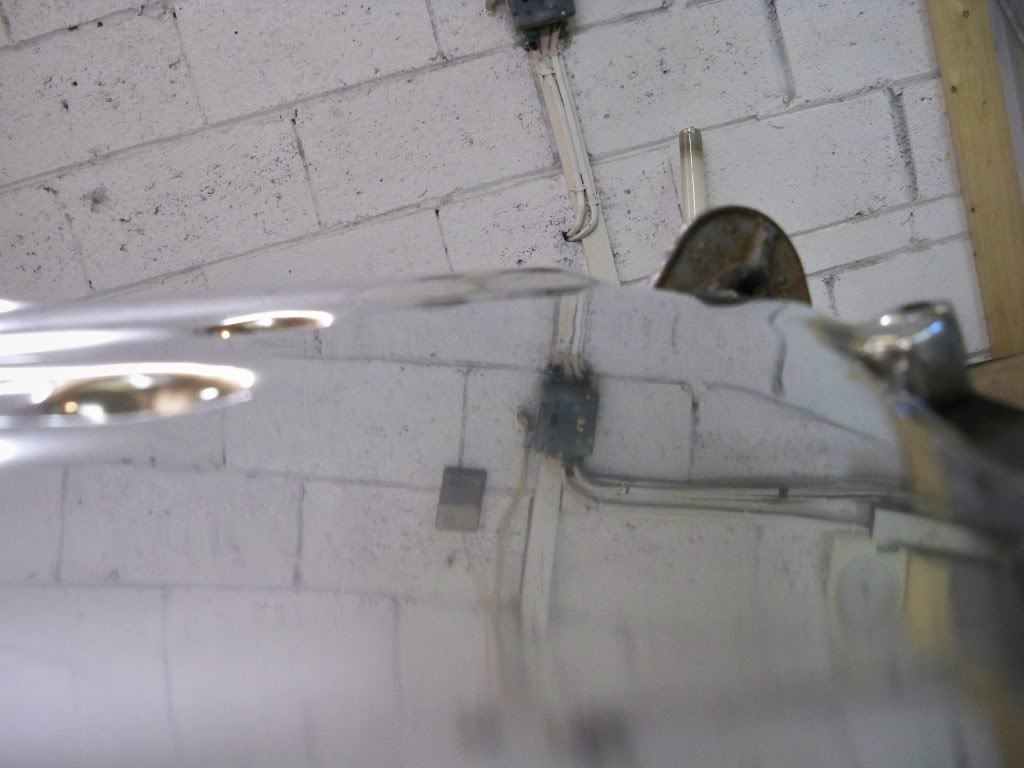
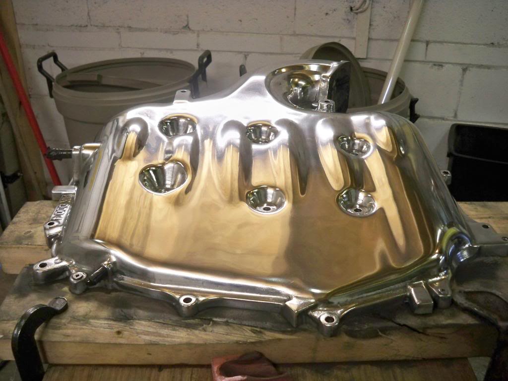
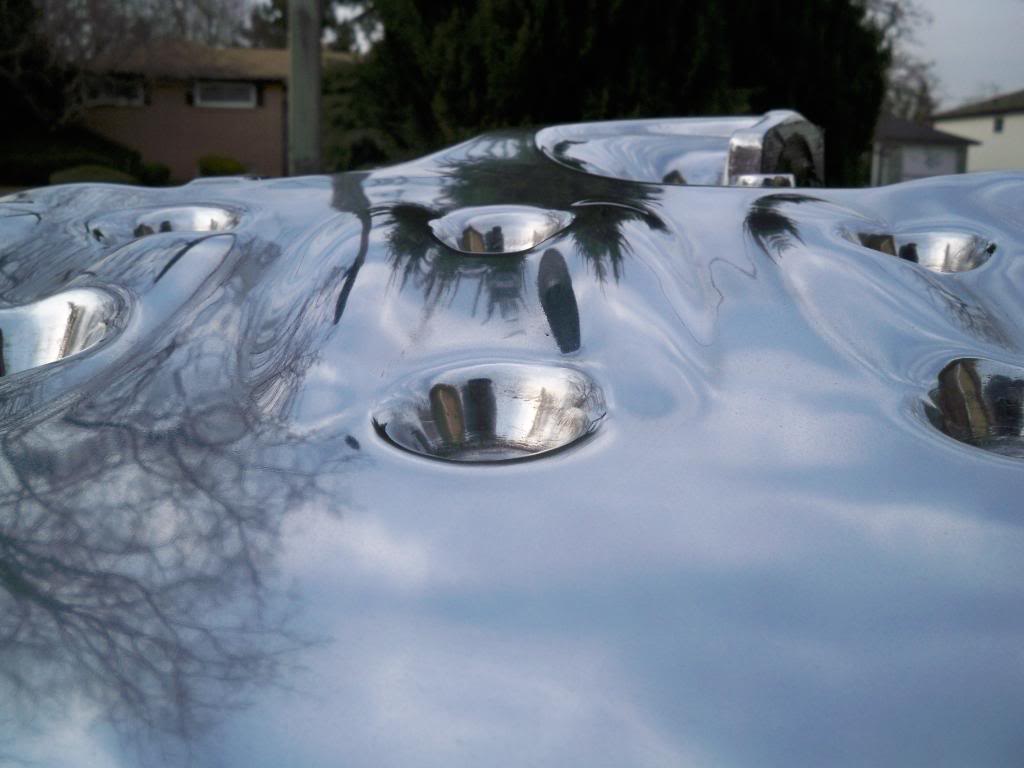
–HERE ARE THE PICS AFTER 25 HOURS OF WORK—
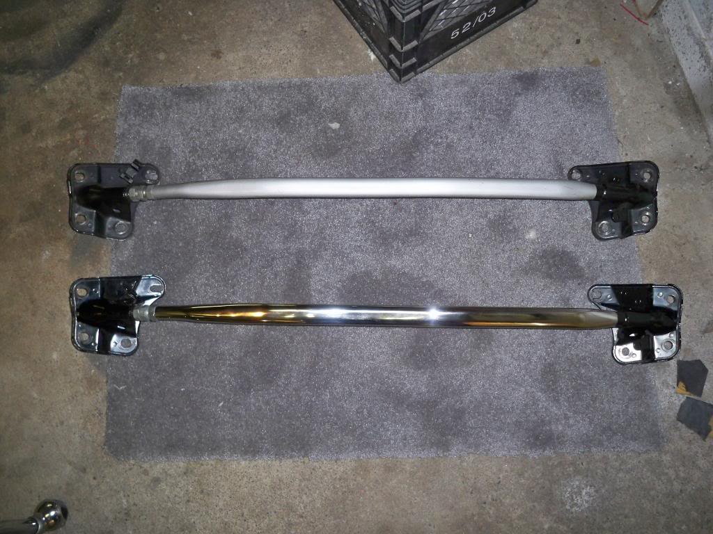
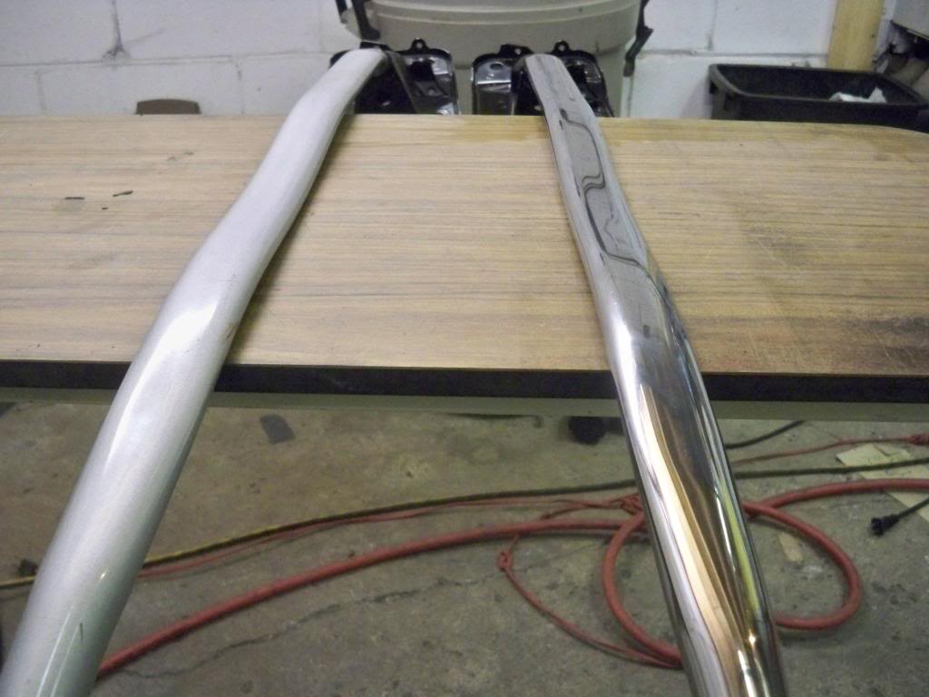
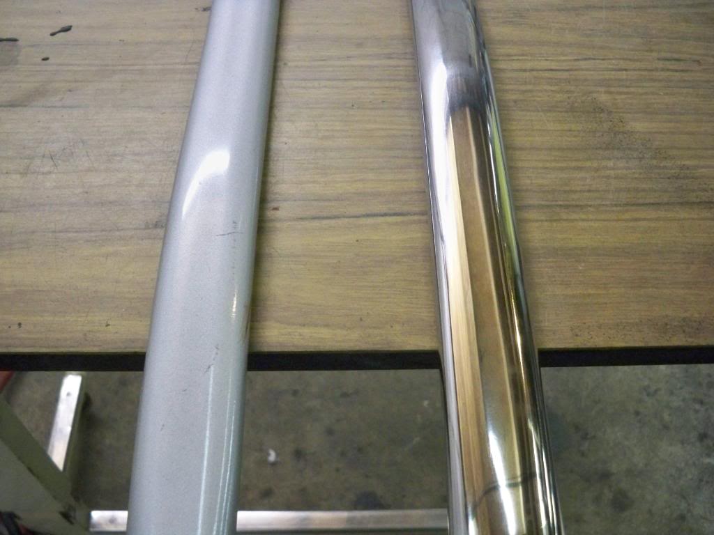
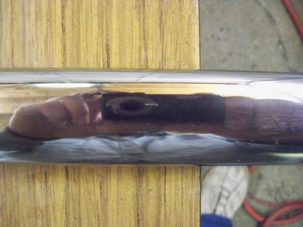
I also polished my strut bar. The bar is made of steel not aluminum so it can rust. The bar is not on the bar and was finished 4 weeks ago. It has been stored in the garage since then and shows no signs of rust. I am thinking/hoping that if I keep a protective coating of polish on the car it will not rust. If it does rust I will sand it again and clear coat it, or just reinstall my other oem bar.
Here is some of the equipment I needed to complete this project
-5 inch electric orbital sander
-Rotary tool with and assortment sanding wheels, flap wheels and wire wheels.
-Air grinder
-an assortment of felt/cloth wheels
-220 grit sand paper
-400 grit wet sand paper
-800 grit wet sand paper
-1000 grit wet sand paper
-black compound/bar
-Red compound/bar
-Metal polish
———
i am not sure how long this took me, maybe 2-4 hours total.
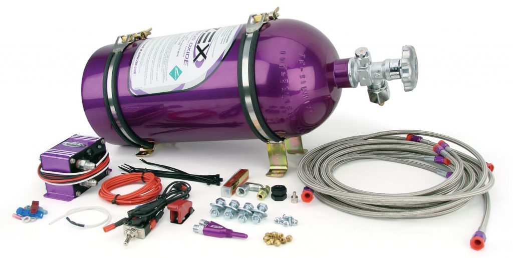
These are instructions on how to install a wet nitrous kit in your 6thgen. This is pretty straight forward but if you have any doubt please take it to someone who knows how to install these systems. The Zex model used for 6thgens is usually the 82016 Model. Below you will see all the items that come with it. This does now show hot to install the bottle warmers, heaters and window switch. This is for the main nitrous setup. The accessories will be discussed in the information thread with pricing.
Items Included in Kit § Nitrous Management Unit 1 Mounting Bolts and Nuts 1 § 10 lb. Nitrous Supply Bottle (unfilled) 1 Arming Switch/Wire Harness 1 § 4 ft. Stainless Steel Braided Hose, -3AN 1 Wire T-Taps 2 § 16 ft. Stainless Steel Braided Hose, -4AN 1 Barrel Connector 1 § Nitrous Spray Nozzle 1 Spade Connector 1 § Bulkhead Fitting Assembly 1 Ground Ring Terminal 1 § 1/16 NPT Tap 1 Black cable ties 10 § 3 ft. Length of Rubber Hose (3/16 SAE30R/KY) 2 Grommets 2 § Hose Clamps 4 Instructions 1 § Tall Bottle Bracket 1 32 Tuning Jet 1 § Short Bottle Bracket 1 36 Tuning Jet 1
Installation Instructions
1. Decide where to put everything. Before you drill a hole in your car, make sure you know where you’re going to install the various components of this kit. You’ll have to discover the best positions for each component by trial and error. First, the nitrous line that attaches to the engine air intake is about 4 ft. long. That means where you choose to install the nitrous nozzle decides, with a 4 ft. radius, where you have to mount the nitrous management unit (NMU). Also, you need to connect the vacuum/pressure circuit for the fuel pressure regulator to the NMU, so be aware of the distance between these components. You’ll also have to decide where to install the arming switch and nitrous bottle. The arming switch should be installed in a position convenient to the driver, but not in an area that increases the chance of unintentionally arming the system. You’ll have to run a wire through the firewall to the NMU. Do it just like you would run a lead for your stereo system. In fact, if you have one installed, you can probably run the arming lead through the same grommet. If not, try to use a wire loom hole that is grommeted. To help decide where you’ll mount the nitrous supply bottle, check the following section for technical restrictions on bottle mounting locations and positions.
2. Mount nitrous supply bottle. Mount the nitrous supply bottle so that it is separated from the passenger cabin. Fastback style cars that do not have a separate trunk compartments have to be equipped with a safety blowdown tube. Route the tube from the safety pressure relief cap to the exterior of the car, preferably under the car. Doing so will prevent your car from filling with a cloud of nitrous oxide should the safety pressure relief cap rupture. Index the pickup tube with bottle position (Fig. A, B and C). ZEX™ nitrous bottles are designed with the bottom of the siphon tube at the bottom of the bottle towards the outlet. Always mount the bottle so that as your car accelerates, the liquid flows toward the pick-up tube.
3. Mount nitrous delivery line under the car. When routing the nitrous delivery line under the car, try to use the sub-frame as a conduit. This protects the line and eliminates the need to use clamps. The supplied cable ties work if you can run the line higher in the under-body so that it’s safe from the road level obstacles such as speed bumps. For the pro-race look, you can use steel loom clamps with rubber sheathing to fasten the line to the body.
4. Mount nitrous management unit. Keeping in mind the length restrictions of the nitrous nozzle feed lines, mount the Nitrous Management Unit in a suitable location. Use the four screw holes provided for this purpose. It’s a pretty rugged piece of equipment that is built to withstand underhood temperatures as well as exposure to weather.
Note: I had to mount mines upside down for a better fit.
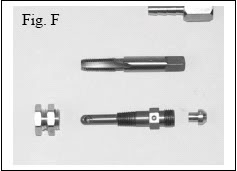
5. Install nitrous nozzle. Optimum nozzle placement is 6” to 18” from the throttle body. After you have determined where to mount the nitrous nozzle in the intake, make sure this location won’t interfere with other components. If your engine uses a mass air flow sensor, mount the nozzle after the sensor but before the throttle body. After you’ve found the spot, mark it and remove the air inlet duct from your engine. Drill a 7/16-inch mounting hole and install the bulk head fitting. Be sure to remove any drill shavings since they can severely damage your engine. Install the nitrous nozzle so that the spray is in the direction of airflow. Also enclosed is a tap should you need to mount the nozzle in a metal duct. Just drill a ¼- inch hole where you want to mount the nozzle, tap the hole and install the nozzle. Once installed, place the appropriate tuning jet in the nozzle and attach the 2-foot long, -3AN hose over the nozzle end.
6. Install regulator and intake hoses. Measure and cut to length the two hoses that lead from the NMU’s regulator and intake hose barbs. The regulator hose barb from the UMU gets connected to the vacuum fitting on the engine’s fuel pressure regulator with one of the lengths of hose. The intake hose barb from the NMU gets connected to an unused vacuum fitting coming off the intake manifold plenum with the other length of hose. Install the fuel tuning jet in the holder as seen in Fig. G and tighten the hose barb/tube nut assembly over the top of the jet.
7. Wire it. Once you have mounted the components, you are ready to wire the nitrous system. From the Nitrous Management Unit, find a suitable ground for the black wire and connect to it with the included crimp-on ground ring. Run the red wire through the firewall of the vehicle into the interior, behind the dashboard. Ensure that the red wire passes through a grommeted hole and not a bare metal hole. The wire’s insulation may be rubbed off if put through a nongrommeted hole. Run the white wire from the NMU to the output voltage lead from the throttle position sensor. After these connections are completed, you need to install the arming switch/wire harness assembly. Find a suitable place in the interior of the vehicle for the arming switch and drill a ½-inch (.500) hole.
Mount the switch and switch cover through this hole. Take the lead that the fuse assembly is attached to and find a suitable 12 volt accessory source of power under the dash. Use the T-tap electrical connector to splice into the 12 volt accessory wire and plug in the wire harness lead. Take the other lead from the arming switch and connect it to the red wire from the Nitrous Management Unit. As a reference for wire locations, use Fig. D
8. Program activation switch and check vacuum and pressure lines. Now that you have completed the wiring of your nitrous kit, one of the final steps is to program the activation switch and check the vacuum and pressure lines. To program the Activation Switch, turn the vehicle’s ignition on, but do not start the engine. Turn the nitrous arming switch to the “ON” position. Go to the Nitrous Management Unit (NMU) and locate the push-button switch. Depress, then release, the push-button switch. Observe the NMU’s Operation Light. At this point, it should be RED. This RED light informs you that the NMU’s Activation Switch is in learn mode. Return to the driver’s seat and depress the accelerator pedal to the floor, holding it there for 10 seconds. Release the accelerator pedal and go back to the NMU and observe the Operation Light. At this point, the light should be flashing continuously from RED to GREEN to OFF. This is the NMU’s way of telling you that it has successfully learned the voltage curve of your engine’s throttle position sensor. Go back to the driver’s compartment and turn off the system’s arming switch, then turn it back on. Go back to the NMU and observe the Operation Light. It should be solid GREEN at this point. This informs you that the system is armed and ready to activate at wide-open throttle. Return to the driver’s seat and depress and release the accelerator pedal several times. You should hear the solenoid click each time you reach wide-open throttle. At this point, your Activation Switch is fully programmed and ready for use. If you ever transfer your nitrous system to another vehicle, perform this same procedure on the new vehicle to “relearn” the NMU’s Activation Switch. To ensure that the system is ready to be used, a final vacuum and pressure check of the system’s hoses and lines must be done. With the engine running, check your “intake” and “regulator” hoses for any vacuum leaks. Generally a vacuum leak will cause the engine to run rough. Assuming the vacuum lines check out, open the nitrous bottle valve. Listen carefully to your engine as the valve is opened.
You should not hear a difference in idle speed or engine sound. If you notice either of these changes, call our NITROUS HELP™ line at 1-888-817-1008. If there is not change in idle speed or engine sound, shut the engine off at this time and inspect the nitrous pressure lines and fittings for leaks. Leaks in the nitrous supply line will be obvious because they will be covered with frost.
9. Check fuel quality and ignition timing. The last thing to do before enjoying your new nitrous system is to ensure that premium fuel (92 R/M Octane or better) is in the fuel tank and that your ignition timing is set correctly. All recommended ignition timing retard amounts on the Tune-Up Sheet are calculated off of the base, stock ignition setting. It is important to set this with a timing gun before you use your nitrous system for the first time. Do not assume that it is set properly. If the ignition timing is not set correctly, severe engine damage may occur.
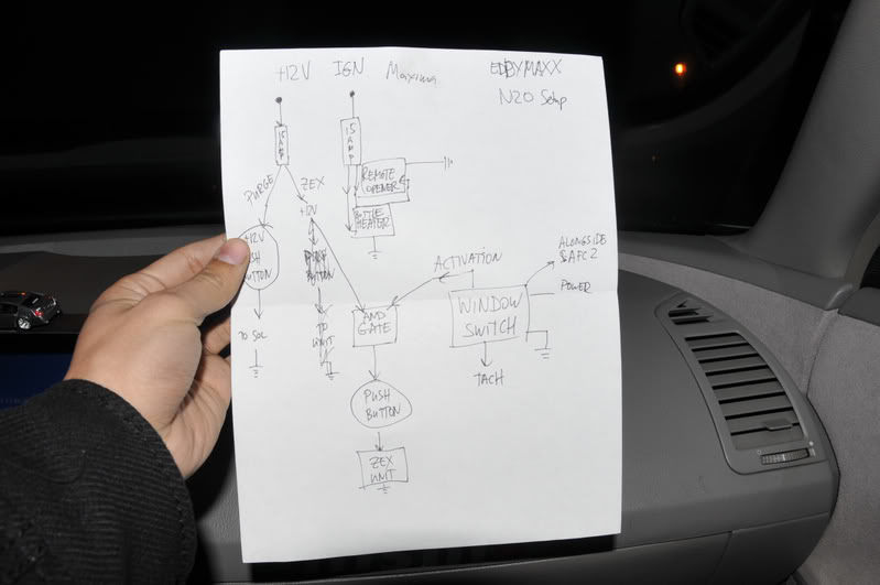
10. Window Switch Diagram (Only if you plan are using one)
ZEX™ #82016 Tune-Up Sheet Premium quality fuel, 92 R/M octane or better, is required at all times for safe operation of your ZEX™ Nitrous System.
WOOHOOOOOOOO!!!!!!!!!!!!!!
Just chilling…The Beast from the East!!!
It is the responsibility of the installer to ensure that all of the components are correct before installation. We assume no liability for any errors made in tolerances, component selection, or installation.