So I did the 6 speed swap a couple of years ago following the guide in the stickies. I did a lot of research on the swap and thought I would improve the guide a bit by consolidating the information I found, fixing some grammatical errors, and adding some of my own experiences to the mix. I’ve added the part prices and who I bought them from for reference, although I would recommend swappers find parts locally. I didn’t include any pictures from my swap but the same ones in the original procedure thread apply. If I’m missing information or information is wrong, let me know.
REQUIRED PARTS
6spd Maxima transmission-junk dealer Action Auto Parts $620
5.5 gen 6spd Maxima shifter assembly- junk dealer Riverside Auto Parts $90
5.5 gen 6spd Maxima shifter cables- 05 Max cables Pence Nissan $160
5.5 gen 6spd drivers side axle- DO NOT BUY GSP brand from Advance Auto Parts, stock 4th gen may be used
5.5 gen 6spd passenger axle (must be OEM) – EBay seller $150, DO NOT BUY GSP brand
6spd frame transmission mount (11220-5Y700)- CourtesyNissan $86
6spd transmission mount bracket (11253-AU400)- CourtesyNissan $36
aftermarket Maxima 6spd flywheel w/ bolt on timing ring (Jim Wolf, Fidanza, etc.)- UltraRev Clutch/FW Ebay Package $631
Check the 5 speed removal guide for information on removing the 5 speed parts.
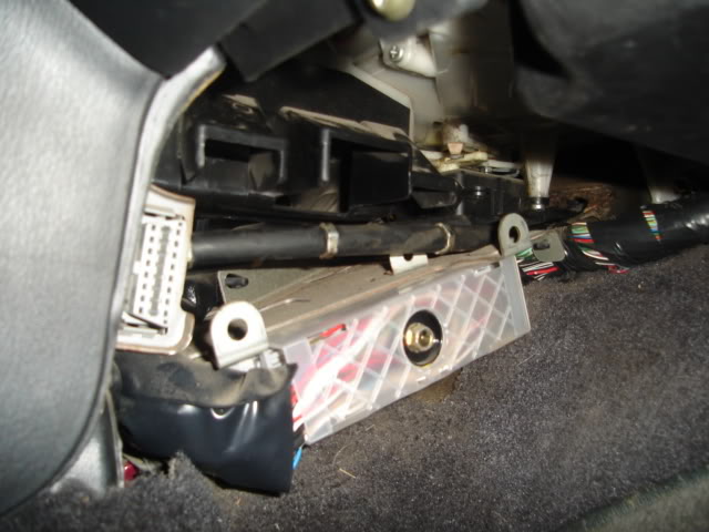
1. Install shifter cables (Method 1)– Route the cables through the passenger side. Pull off the A/T control cable cover and snake the cables in above the ECU. No need to drill through the sound deadener, but boring out the hole wouldn’t be a bad idea, as it can be hard to move and bend the cables to route them properly.
It will be necessary to drill into the shift cable cover as the pre-drilled holes will not line up.
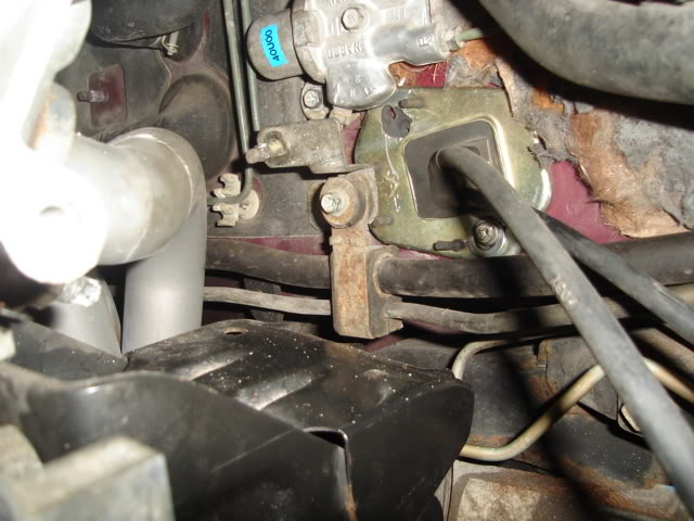
Apply weather insulating/sound deadening material such as Dynamat (shown above) on the firewall hole to keep road noise and water out.
2. Install shifter cables (Method 2)-If the A/T control cable hole was not drilled into the firewall from the factory, or is otherwise inaccessible, use the manual A/C control cable hole in the firewall, right above the fuel filter. It will require about 2 inches of boring out (towards the bottom) to fit both cables. Apply insulating material to the hole to keep water out.
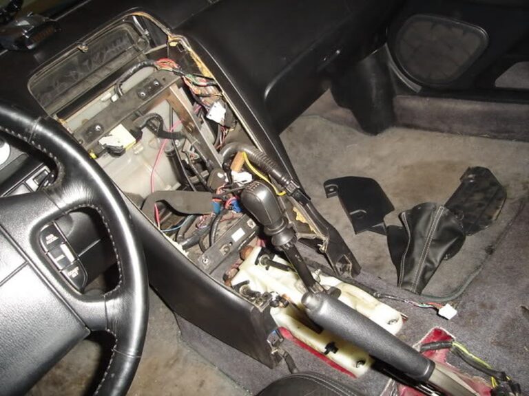
3. Mount shifter assembly– Pretty easy to do also, but it needs to be slightly modified. There are bushings on each of the 4 bolt holes, these bushings must be taken out in front because, if not, the bolts attached to the floor won’t be tall enough to be used. You will need 2 pairs of nuts and bolts for the back holes.
4. Taking off the old 5spd mount– Cut off the old 5 speed mount with a suitable cutting tool (angle grinder and bolt cutters work well). Cut and grind the extended part of the mount bracket as close as you can to the frame so that the new mount can go on relatively flush to the frame.
5. Install 6spd flywheel– Take the 6spd CKPS ring off your aftermarket flywheel and align that timing ring with your custom ring (these custom timing rings MUST BE PRECISION MACHINED to avoid spark timing issues). Then drill out the corresponding mounting holes. Then reattach the timing ring with the supplied bolts and some blue locktite if desired. Since you are using a 5spd CKPS, you don’t need to clock the timing ring, so just install the flywheel by aligning the dowel pin and tightening the bolts in a criss-cross pattern, to the torque specs.
Fidanza Maxima 3.5 flywheel installed:
Make sure to clean the pressure plate and flywheel well with brake cleaner, and torque all mounting bolts to the correct specs in the correct sequence. With Fidanza flywheels, it is even more critical to torque all bolts correctly to prevent stripping threads from flywheel or pressure plate mounting bolts.
6. Trans mount install– You can either weld this mount to the frame or bolt it to the frame. If you do decide to bolt it to the frame, you will either need to cut a small, rectangular hole in the outward facing side of the frame to be able to anchor the bolts with the mounting nuts, or you can try drill through both top and bottom of the frame (the frame is hollow inside), vertically aligning the drill points. You will need to install the transmission on the engine to align the mounts. Get the transmission on, use a couple bolts to get the transmission flush with the block. Reinstall the front cross member if unbolted. Bolt on the transmission-mounted bracket on the transmission, and then attach the frame-mounted rubber mount with the mounting bolts. Then set the frame mount flush on the frame and mark the holes. Unbolt both brackets, lower the front cross member, and uninstall the transmission if necessary. Drill the holes for the mount. Then cut the rectangular hole on the outward facing side of the frame and tighten the nuts onto the bolts, securing the frame mount.
7. Moving the ABS modulator (if equipped)– The modulator is bolted to a bracket, which bolts to the inner frame rail. This bracket needs to be gotten rid of. Use zip ties to pull it upwards by the master cylinder.
8. Transmission install– It’s easiest to do with someone under lifting it up and someone up top helping. Remove the transmission-mounted shifter and shifter cable bracket to gain clearance. It may be necessary to grind down part of the frame to get the transmission on (shown below). Make sure the mating surface between block and bell housing is clean, to avoid starter grounding problems. Torque the transmission bolts to spec and in the proper sequence. Reinstall the shift cable bracket and shifter. Raise the front of the sub frame, so the cables can be attached to the shift assembly using cotter pins and the cables installed in the bracket using the appropriate clips.
Attach the mount bracket to the transmission. Then jack up the transmission/sub frame, so the 2 mount parts can be joined. Torque the front sub frame and the mount bolt to spec.
9. Starter install– The 6spd starter ground cable is a female connector, so is the connector on the engine harness. You may either cut both connectors off and solder them together or cut the male connector off of a 5spd starter and solder it onto the 6spd starter.
10. Relocating CKPS– If you are using a FWD 6spd Fidanza flywheel, no further action is required other than reinstalling the CKPS sensor in its original location. The crankshaft position sensor (CKPS) hole will need to be enlarged, and a new hole for the mounting bolt will need to be drilled and tapped IF the RWD 6spd Fidanza flywheel is used. The RWD 6spd flywheel has a different timing ring offset than the FWD 6spd flywheel.
Draw a line on the bell housing and on the CKPS; bore the hole out to the driver’s side, until the car will start and run. Then mark, drill, and tap the hole. The tap for the hole should be 6.7mm. Use the “Making Your Own CPS Ring” guide to make your own CKPS ring that does not require CKPS relocation, or use a precision machine shop to make the ring.
Extra Information
JonBlz said: You can tell if you have HLSD by checking the tranny code at the end of the code it should have H.
HotshotVQ35 said: people who upgrade get the 04+ cause of a short final drive, and i think the 3rd gear grind is gone also.
Derrick2k2SE said: 02-03 trannys are the same. Yes, they are notchier than the 5-speed trannys. They still feel good and and I wouldn’t consider it a deal breaker at all.
The 02-03 trannys are prone to what we call the “3rd gear crunch” where the syncro wears out and causes a crunch when shifting into 3rd fast from a high RPM. It won’t cause a complete failure, it’s more of an annoyance.
They fixed the issues 04+ trannys. They’re smoother too.
The HLSD does make a huge difference in these cars. It’s kind of a rare option though. Finding a car that meets your other requirements AND has HLSD will be hard.
Go here http://car-part.com/ and get a low mile HLSD 04+ tranny and swap it in. It’s a direct fit with no issues.
scrhale said: Just for people in the future. The code is indicative of what is in the tranny. RS6F51H is the one everyone wants. The 6 means 6-speed and the H means Helical/HLSD. Don’t buy transmissions with a 5-code or an A (open differential) on the end.
1. ECU pinout for 99 is much different than 95-98’s. Regarding installation of the EU, pin 44 needs to be changed to pin 46.
2. Jumper Pin 13 must be set to OPEN (not 1-2 as shown on page 27 of Dan’s writeup), otherwise your fans will not kick on and your car will overheat. I’ve tested this. Thanks for the footnote Dan!!
3. The 99 FSM is all screwed up, so don’t go by it. Hours and hours were wasted trying to figure out the 99 FSM and compare it to the other year FSM’s I have. The 99 FSM led me to believe that 3 pinouts had to be changed at first. Before I hacked or cut a single wire, I did a continuity test (per Dan’s recommendation) and figured out which wires were really what. Only one wire on Dandy’s ECU diagram had to be switched as stated above.
4. My Emanage Ultimate is version D. I don’t have any CEL’s!!
This illustrates that resistors don’t need to be soldered in (for version D).
5. Also, I have no issues with burning/melting coilpacks as some have experienced.
Last but not least, I would like to give a big thank you to Dan (Dandymax). I sent him 3 or 4 emails asking for help/clarification on several issues before the install. Dan always got back to me within 24 hours or so and provided in-depth explanations. With his awesome write-up and his “tech support”, he made the install a breeze and trouble-free. Lastly, I found many, many mistakes in Greddy’s install manual (more on that later), but couldn’t find one in Dan’s writeup! Great job Dan!
Additional Info
The red connections you see are for the wires that get tapped. The taps are 2.5″ of wire with a female connection on the end. I crimped a male connector on each of Greddy’s bare tap wires. It did it this way so the EU can be removed quickly and easily from the system if need be.
The clear connections are the connections Greddy provided and are for the intercepted lines. It worked out really nice because Greddy would put a female connection on say Injector #1 IN and a male connection on the Injector #1 OUT. All I did was crimp on the opposite of each onto the OEM harness. If the EU is taken out of the car, the female/male Greddy connections will join together and the car is back to stock.
I plan on installing it under the seat and running the harness cable under the center console for a super clean look. When it’s done, it will look like it’s not even there……
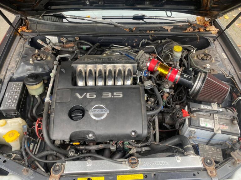
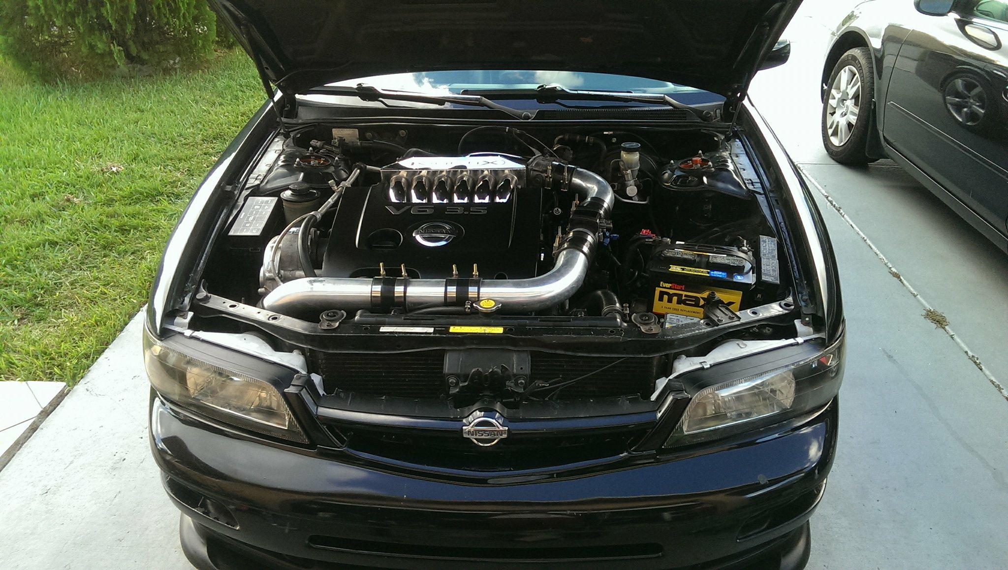
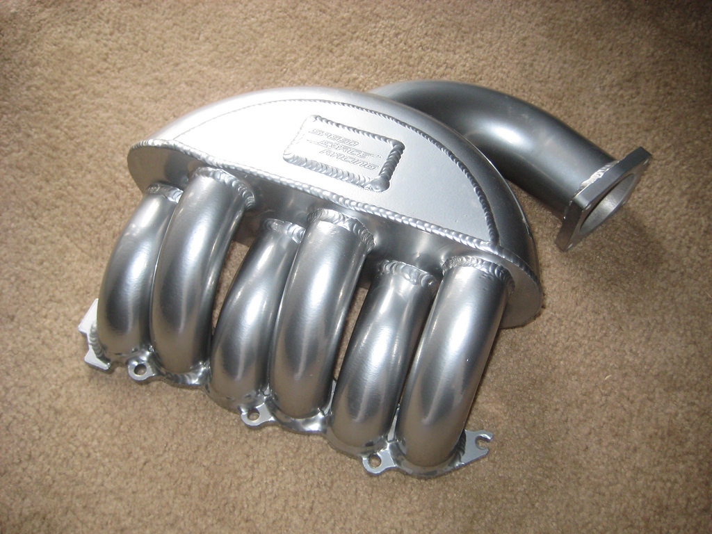
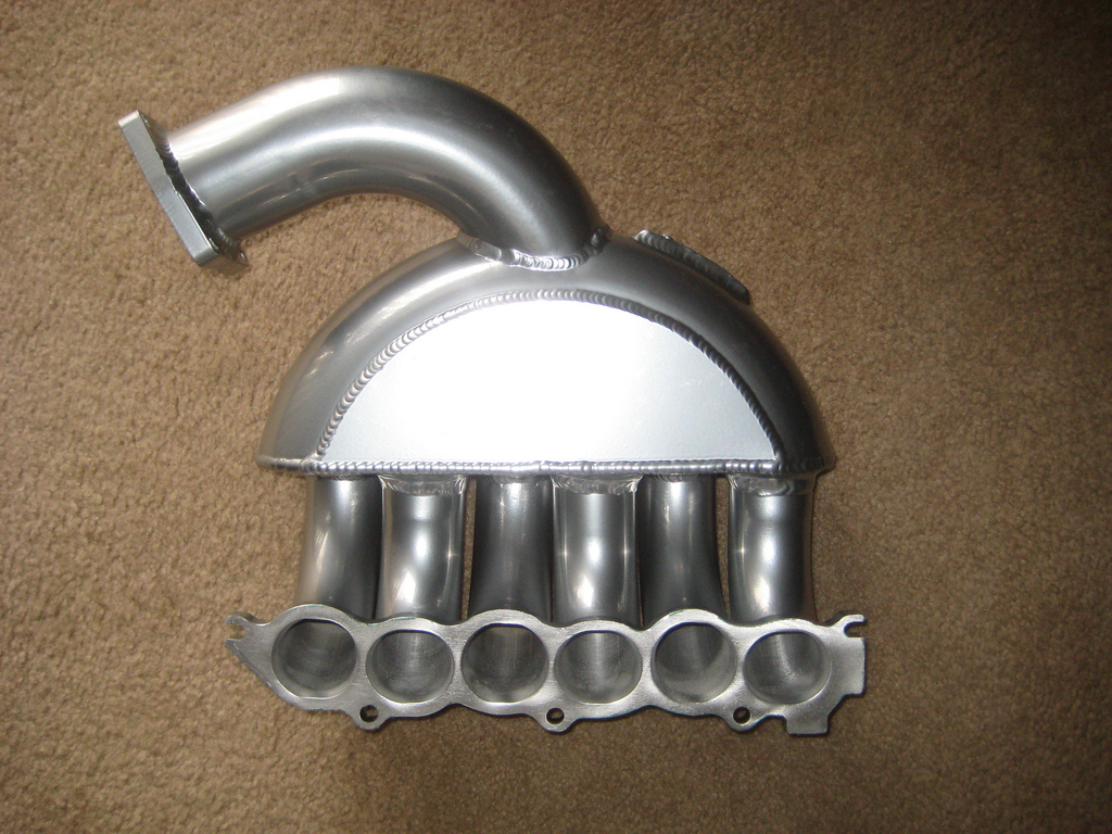
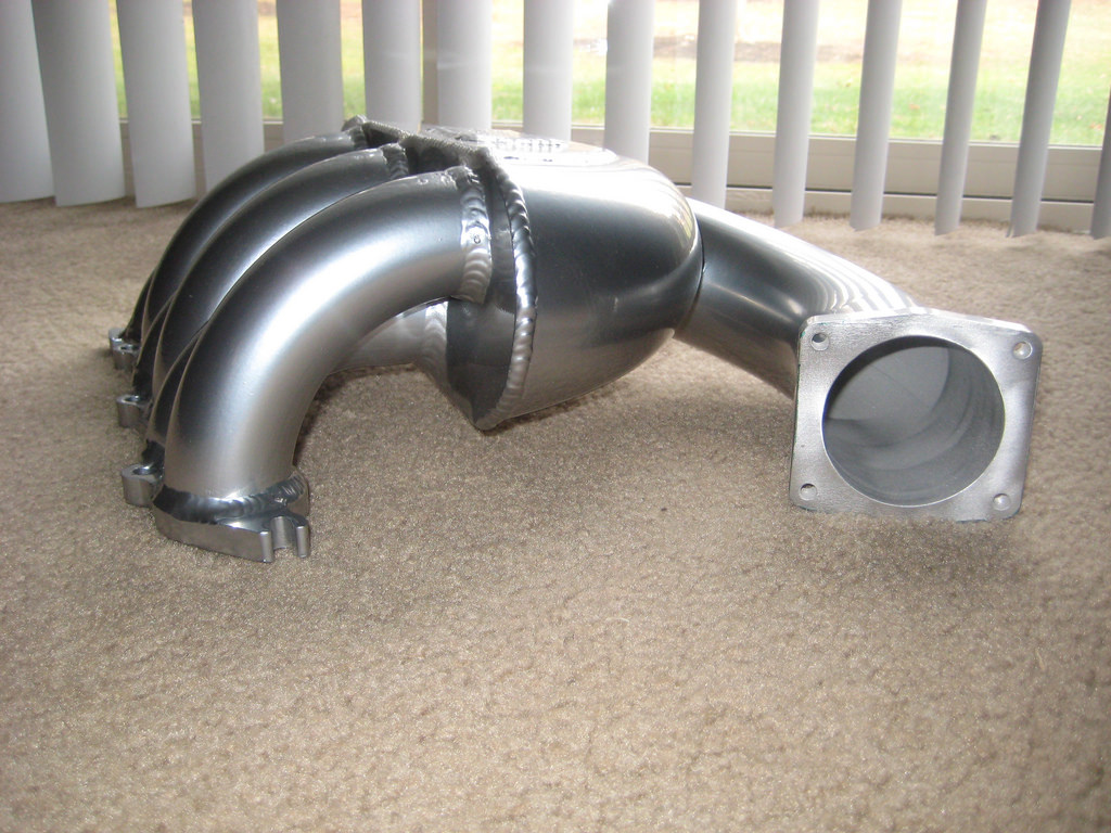
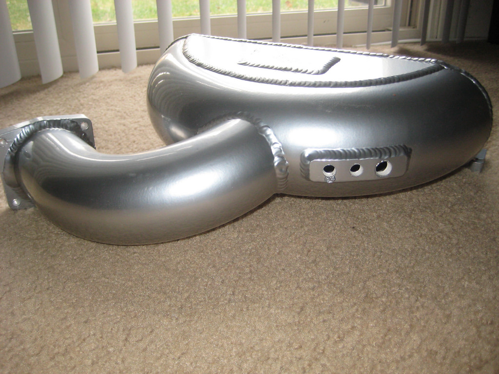
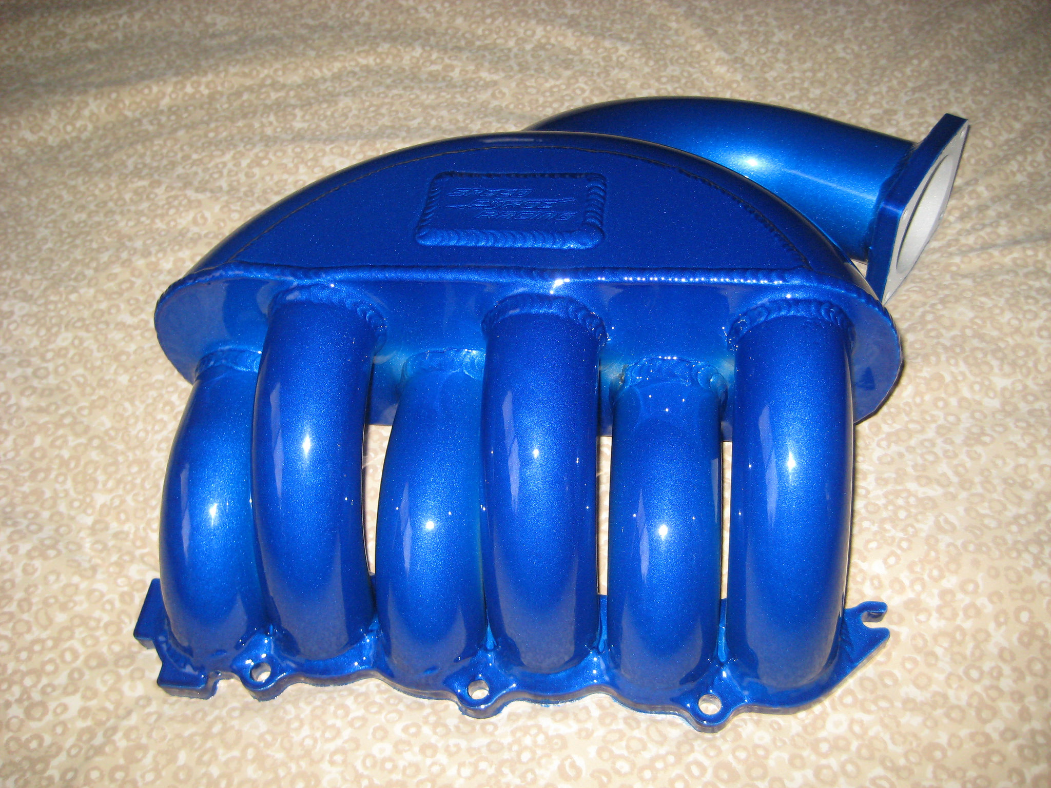
If you want to add an easy 25WHP to your Altima or Maxima then look no further. Our SFR high-velocity manifold is an easy bolt-on and adds 25WHP to an NA car and up to 50WHP on turbo cars. We also offer an aluminum engine cover that goes with it to really dress up the engine We also offer the intake manifold for the later models Altimas and Maximas.
Nissan Club
I was fortunate enough to have the first SFR High-Velocity Manifold put on a N/A vq35. From what Tim at Speed Force Racing told me this manifold is slightly different from the manifold made for forced induction cars.
I have had the manifold for months. When I first received it I was impressed with what I saw. The design is wicked and looks waaaayyy better than stock. It took me a while to slap it on at first because I had to find and purchase the correct barb fitting to hook up the vacuum hoses. At first, the installation was a bit time-consuming because I didn’t know what I was doing. I have installed the manifold on and off about 6 times already so installation for me is under an hour.
The sound is pretty cool. At low revs during soft acceleration, you hear a humming/growl from under the hood. Under hard acceleration, the engine sounds great! it isn’t loud and obnoxious. It’s more of a deeper growl, nothing too crazy or far from stock, but noticeable.
At first, I could only go off of the butt dyno and my butt dyno liked what I felt. To me, the mid-range was increased a lot. I knew the torque was increased a lot (dyno showed 10wtq at peak). Up top, the car felt great as well. My car just easily pulled to higher RPMs. I could definitely feel the car breathing MUCH better. Even while cruising at lower RPMs the car had sooo much better response.
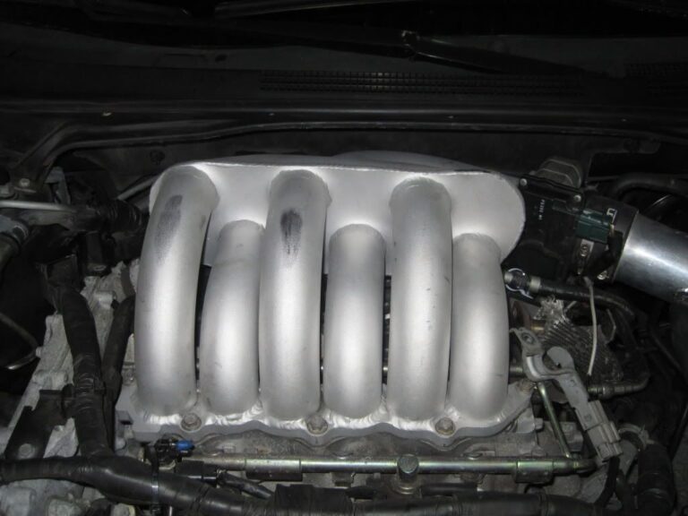
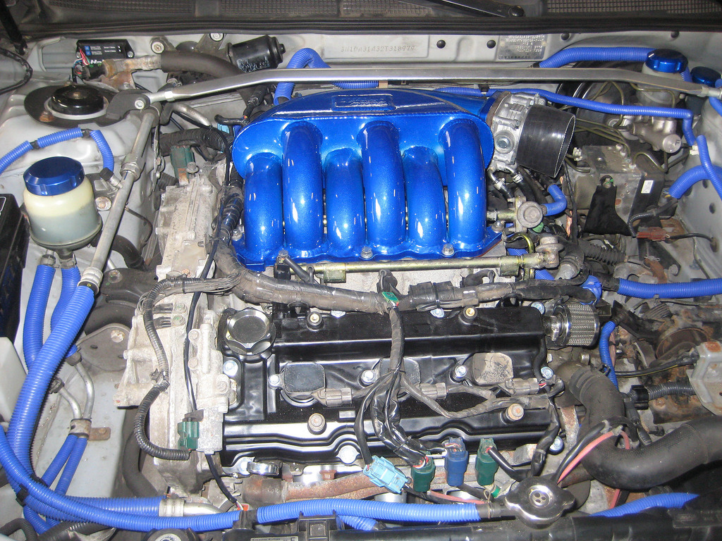
Here are some pics of what it looks like on my car:
Some graphs got mixed up at the shop but I managed to get the most important ones. The graph shows the highest dyno from the stock manifold with the highest dyno with the SFR manifold. the other graph has the highest stock vs. a couple runs with the SFR manifold but also shows the torques as well.
I picked up almost 30whp at redline alone.
I was amazed at how much power was picked up at redline. this isn’t your average SSIM dyno graph only showing gains up top. You can clearly see there are gains on the ENTIRE powerband. Peak rose 5whp (wish it was more). What’s important here is the area under the curve. midrange you can see ~12whp gains as well!
I like this manifold very much! yes, it’s not a cheap mod but for the overall power, it’s worth it. It adds power where cams don’t and cost half the price. Plus install isn’t that hard. To me, it was well worth the money spent.
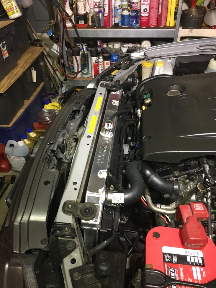
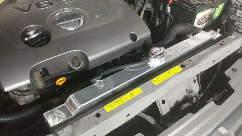
I’ve installed the Megan Racing Radiator and I love it! It’s 1-7/16” thick core versus the OEM 1” thick core. No drain! So what, it has a lower radiator hose. Everything fit the only minor issue is the upper support pegs are slightly lower than OEM & the filler cap is slightly to the right causing the overflow hose to have a little less slack. That’s it fan shroud is closer to my Cattman Headers but they’re ceramic coated so and they don’t really radiate that much heat so applying some of that thermal barrier tape might be a good idea. Function tested it and it works great!
Side by side view with OEM radiator.
Reference Info by SquidBeak
Thanks for the follow up wellshii19.
CMax03, perfect timing! Thanks for the info and the pics. Looks great!
I know it’s overkill, but I really wanted a drain plug. So I bought a bung, drilled the bottom of the radiator then had a local guy weld it in. Then I got an aluminum elbow, plug and a pvc valve for draining. Now, it’s pretty slick. I’m going to do the install this week.
I did a test to see how everything would work this afternoon and I think it’s going to be nice. I was surprised to see that the Megan radiator only holds 1 gallon. I thought it would hold more. I think the original radiator only holds about a gallon also, but I’m not positive about that.
I just finished installing the radiator. Overall, I’m pretty happy with it.
Here are some observations I made in the process:
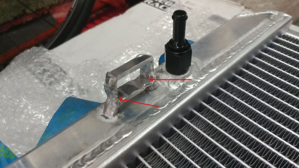
1. I wasn’t very impressed with the AN6-5/16 barb fittings that came with the radiator. They looked like leaks waiting to happen so I used some nicer aluminum fittings. Add 5-10 HP minimum per fitting.
2. I had to file down the welds on one of the fan brackets to allow the fan shroud to fit. Not a big deal. Add 1-2 ponies due to weight savings.
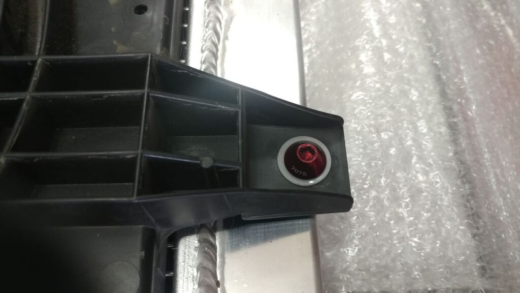
3. The 2 screws that hold the fan shroud on the original radiator thread into plastic and are basically sheet metal screws. You can’t reuse these screws, you will have to get some M6 x 1.0 screws for the new radiator. These cool red screws easily freed up 15 ponies each.
4. The drain plug made the 7-8 drain & fills much easier. Really too bad they didn’t include one. The plug was good for at least 15-20 ponies.
5. This is the most important. The original radiator cap is rated at .9 bar (13 psi). The Megan cap is 1.1 bar (16 psi). With the Megan cap there was no exchange between the radiator and the reservoir at all. None, no fluid nor air. I decided to re-use the original cap and this restored the function of the reservoir. -10 ponies for reusing old cap.
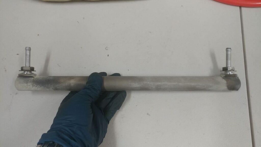
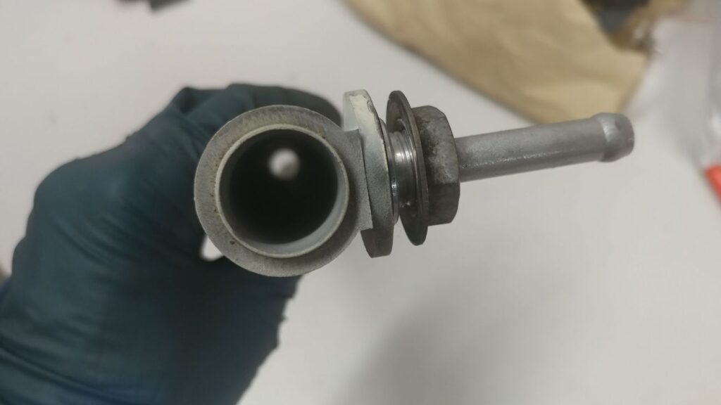
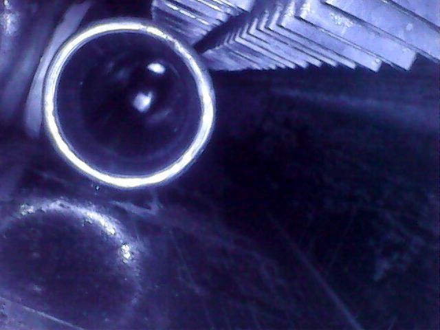
6. I decided to dissect the old radiator mainly because I was curious to see how the trans cooler works. I thought it would be just an aluminum pipe immersed in engine coolant. However, it’s actually a pretty ingenious design. It’s a hollow cylinder that the ATF flows through. This allows coolant to cool the inside and outside of the cylinder. I looked inside the Megan radiator with a scope and it has the same design.
Original ATF cooler.
ATF Cooler side view.
Megan ATF cooler
7. I did the intake manifold coolant bypass while I had the old radiator out. When I pulled one of the hoses off, some black liquid came out. This is strange because all of the coolant looked immaculate when I flushed it. No idea how this could happen. Any ideas? I blew out the coolant lines in the manifold with compressed air then looped one of the spare hoses to the other port of the manifold to plug them both.
8. During a 30 mile test drive, I noticed that the coolant temps now range between 190 and 208. Previously, it was 195-205. It probably doesn’t mean much, but it’s interesting.
9. Easily 50-60 HP gained on the butt dyno. Easily. Probably way more. WAY MORE. Definitely.