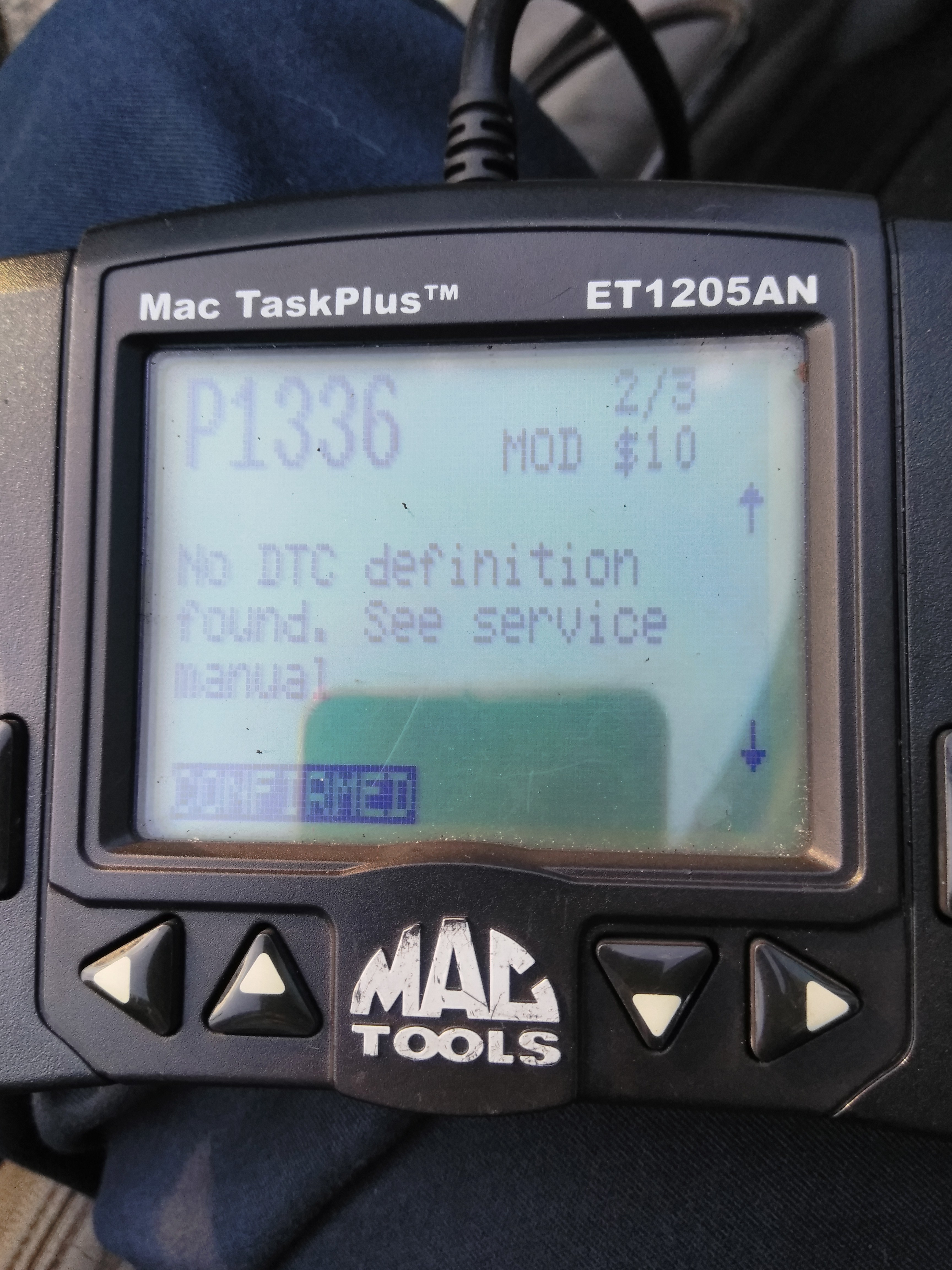
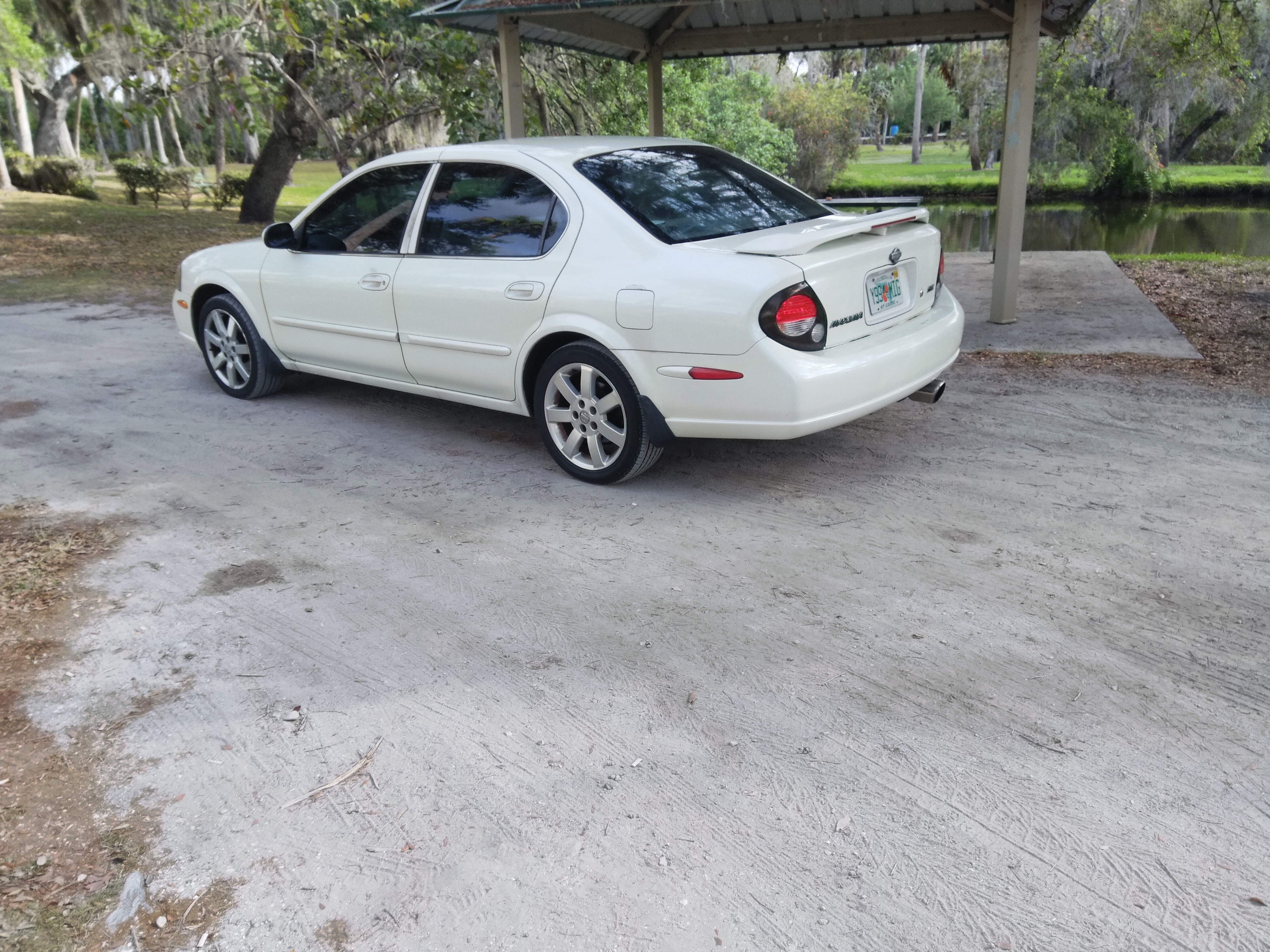
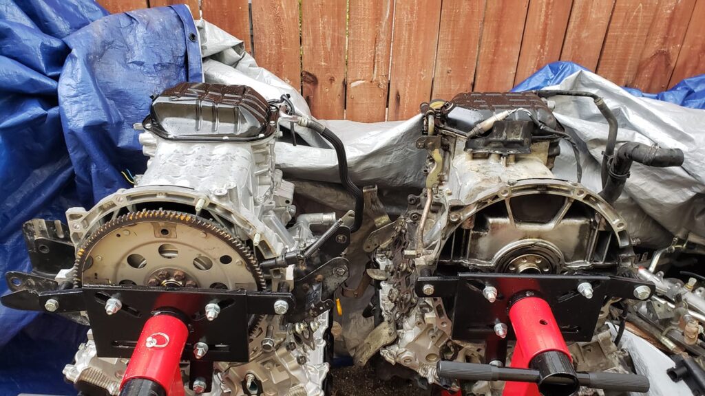
So since i bought the car back in 2010 it had the constant DTC p1336 crank position sensor POS. , it never really was a problem in the past, since the engine ran good, it had a hard start but always started up every time, and other than the DTC i never had a problem. Well i decided to reseal the oil pan since i was passing it on to my son who is going away to college i figured if i do more work on it, the less he has to do to it when it comes time to fix it.
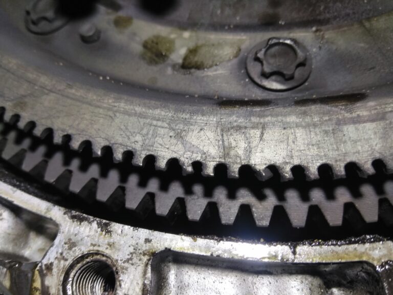
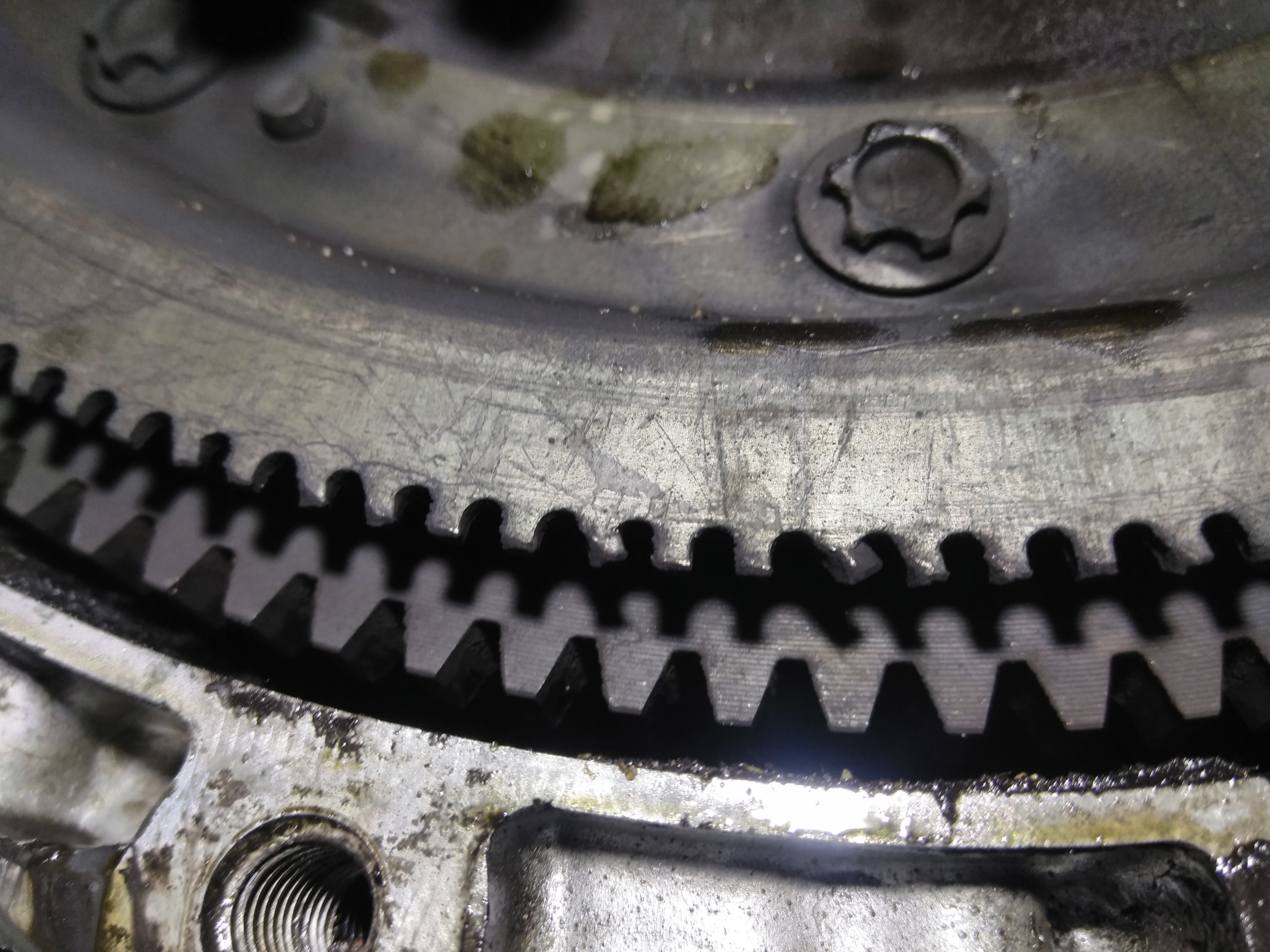
I resealed the oil pan and when i removed the pan low and behold i see my problem is the signal plate that is attached to the flywheel.
The kid i bought it from had the transmission and clutch replaced so when i got it the clutch was new so i had no reason to replace it , and if i had it long enough i am sure i would have had to replace it eventually. .
You can see the signal plate is damaged on the FW , i just wanted to share what i found just in case anyone has the same type of DTC and everything else checks out
Last night, I installed the Rev-up oil pump on my 02 Maxima engine. But before I did, I cracked it open.
Here are some observations.
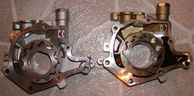
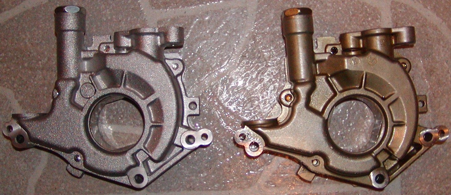
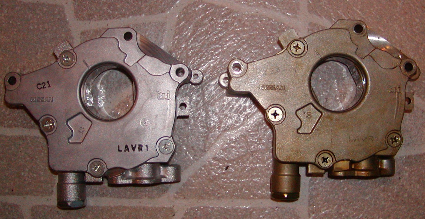
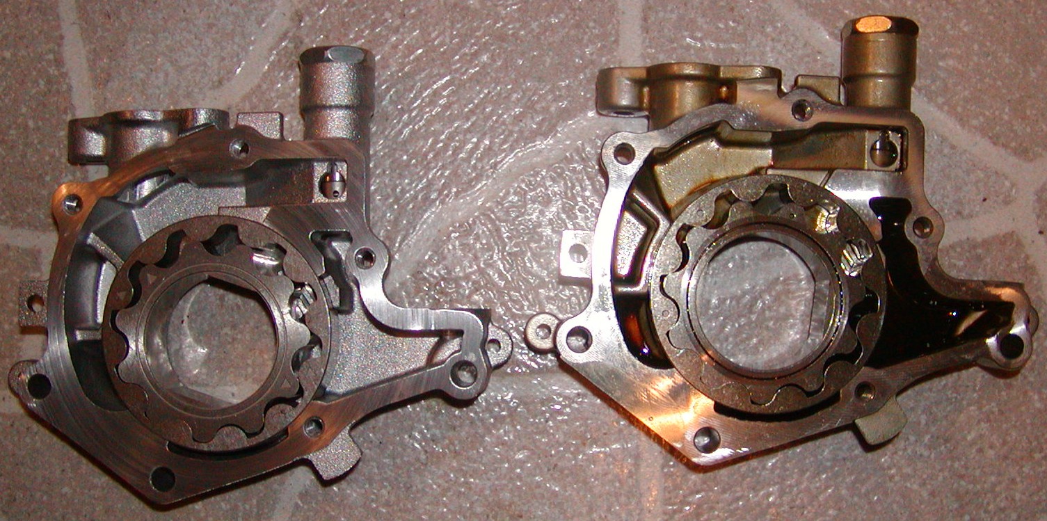
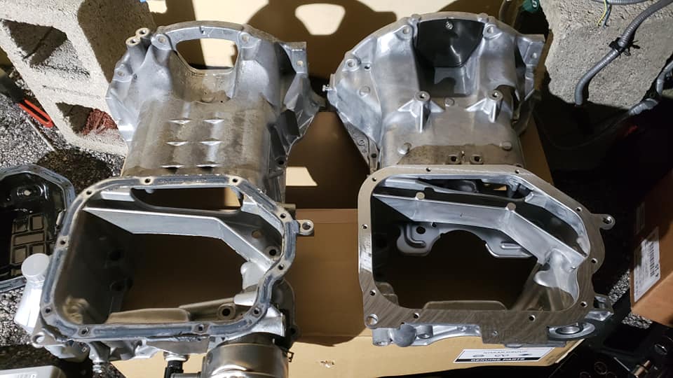
Revup on left; Non-Revup on right
The first thing I noticed was the casing. The non-revup has a smooth casing with several imperfections and burs. The revup has a more consistent cast without any noticeable burs or flaws. Here is the other side:
Here they are opened up:
The first thing I noticed was that the rotors are slightly different. The revup has arrow marks on them and the non-revup has little dots. Other than that, they appear to be identical. I hold them up against one another and the rotor lobes have the same exact shape. The rotor dimensions are identical in every way.
But here’s the difference I found. On my postal scale (displays in .2 ounce increments), the two non-revup rotors weighed 10.0 ounces while the revup rotors weighed 10.4 ounces. There was a clear difference in weight meaning the metal is different.
I also took a few measurements of the inside of the casing. The inlet and outlet inside diameters are exactly the same. And the depth of the casing is exactly the same as well.
I don’t know the major differences between these two oil pumps. But I thought I’d share some of my observations. It appears that the revup oil pump rotors may be stronger. The casing may be a tad stronger as well.
The 7thgen Maxima has a very large MAF pipe diameter which is ALMOST as big as the Land Rover. Nissan knew the HR heads flow a lot more air so they adjusted the intake accordingly. Also, the 2009 Maxima comes with 75mm throttle body.
V2 Supercharger with V2 Aluminum plate kit with 3.0″ Pulley
Only modification I did was shave 1/2 Diameter off the leg located in the center of the SC on the mounting plate. This was to ensure the 3.0″ pulley didn’t have any trouble with the belt. It was done super clean and you will think it was not modified at all if I don’t mention it. It was done by a machine shop.
2.75″ welded alum. charge pipe with coupler from Blower.
2.75″ to 3″0 Bending reducer to connect to the MAF or whatever
Pipes are welded with broken beads at the coupler points to keep them from sliding off.
AEM Dryflow filter 9×6″
Bending coupler 3.5″ (SC inlet) to 4″ Filter Opening
Kenne Bell 8:1 FMU for use with stock injectors
DET MANIFOLD: Consisting of lower, middle, upple plenums. It bolts up to the vq30de/dek block. TPS,IACV etc is 4thgen interchangeable. Idle ,start up etc. are flawless and OEM.
There are also two variations of the 2nd Gen VQ35DE engine. A Maxima engine is equipped with EVT ( Exhaust Valve Timing ) and has a slightly higher compression ratio along with larger intake manifold and throttle body (75mm). The Altima engine has a slightly lower compression ratio, and is not equipped with EVT. The intake manifold and throttle body (70mm) are also a bit smaller.
Notes:
The OBX V2 headers don’t fit with 2020 upper
I used the 2020 new pan, got new headers made. It’s not a big deal.
I just tried to fit a 2020 Vq35 windage tray with a 2002 upper oil pan and it didn’t fit. I had to remove the 2020 one and use the 2002.
I used the 2014 windage tray but had to grind a few spots to make it work. It was hitting the ribs in the 2002 oil pan.
I believe you remove the one on the motor because the wind tray is built into 02 oil pan.
What is the main reason to change the upper and lower oil pans, Is it a height or sensor issue? If it’s just a height issue, can that be solved with the raiser motor mounts? Exhaust issue. Depending what headers/ ypipe you use if they are made for the 5.5 upper oil pan they might not work w the deeper 2nd gen oil pan
Bottom line is it’s best to have the correct oil pan that goes to the car
Obviously a tranny. I used my old ’95 tranny with 108k. (My current car has 180k)
Amsoil synthetic GL-4 tranny fluid. Pricey but recommended.
Alright, step by step removal down to the tranny. First may I note that I think I did this with removing the least amount of stuff possible. I left the cross member on and y-pipe on. Removing these will obviously make removing the tranny easier but is optional. PS: if you remove the cross member you will need to support the engine.
Step One:
Start draining the fluid. Draining the tranny fluid takes a long time so start with this right away. I didn’t and I had to wait for while. This pic shows the bolt that is removed to do this.
Step Two:
Remove the driver side wheel.
Step Three:
Remove the caliper. My 300zx calipers were held on by 2 17mm bolts in the back. Use a wire or zip tie to hold them on the springs so they don’t hang by the brake line.
Step Four:
Remove the Rotors. Mine just slid right off.
Step Five:
Now remove the cotterpin and the washer behind it. Use a pliers.
Step Six:
Remove the 36mm axle nut. Impact gun is strongly recommended. There is also a washer behind it so keep track of that too.
Step Seven:
Disconnect the hub from the struts. It is a 19mm nut on a 17mm bolt.
Step Eight:
Now pull the hub off of the axle. I also used a hammer to help start push the axle out. I again used a ziptie to hang the hub from the strut so it would not pull the ABS line tight.
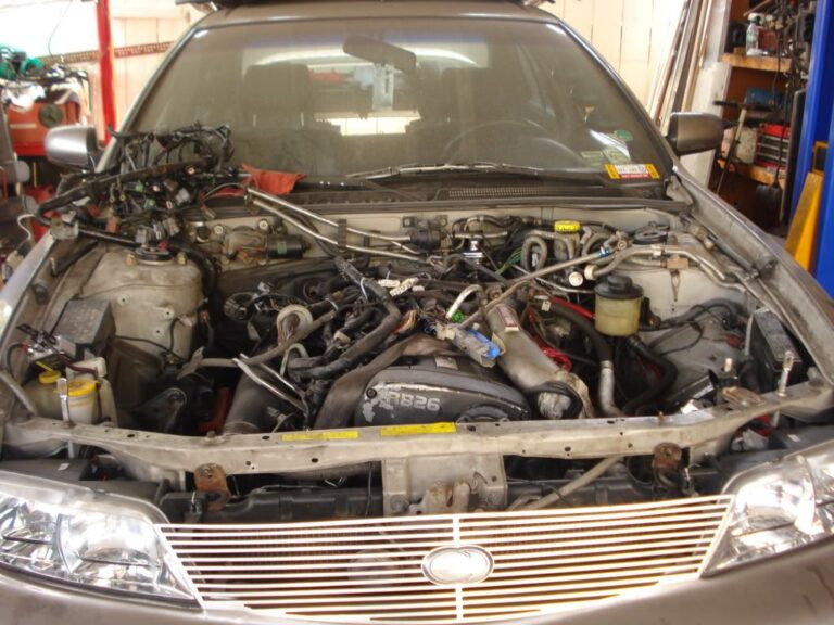
Now to attack from under the hood. Here is my engine compartment before doing anything. Mostly a mess, I know.
Step Nine:
Remove the intake. Disconnect the vac hoses, MAF and air temp plugs, and disconnect from the throttle body.
Step Ten:
Remove the battery and battery tray.
Step Eleven:
Remove the Starter. This involves disconnecting the big positive cable and the other connector. Then unbolt the 14mm and 17mm bolts.
Step Twelve:
Remove the slave cylinder. This was held on I think by two 14mm bolts. They are hard to get at so I had to use a wrench. Then also remove the ground wire that is bolted right next to where the slave cylinder is.
Step Thirteen:
Remove the tranny mount. First remove the long bolt that goes through it. Then the 4 bolts that hold it onto the tranny. Also notice the oil everywhere?…no wonder there is none in my tranny…it is instead all over everything else!
Step Fourteen:
In order to access a few tranny bolts, it is also necessary to remove the shifter linkages/rods from the tranny. It is ok to let them hang from where they connect to the shifter. Also 1 of these bolts is a pain to get at with out taking off the cross member but I did it with a wrench.
(sorry no pics of this)
Step Fourteen point five:
Also make sure the crank position sensor on the tranny is unplugged and the gear sensor is unplugged. I removed the crank position sensor completely.
Step Fifteen:
Now you should have everything off of the tranny. So now remove all the bolts holding the tranny onto the engine. There should be 8 since one was already taken off with the starter and one with the shifter rod. KEEP TRACK OF THE BOLTS! There are different sizes, what I did was I drew a picture of a circle and placed the bolts on the circle relative to each other on the tranny. 2 of the bolts on the bottom of the tranny I could not completely remove with the cross member still on, but I didn’t need to since they were completely unthreaded from the tranny. Once all the bolts are out its time to take off the tranny. What I did which isn’t recommended as the best, was place a jack under the tranny (but not pushing up on it) and then I used a screw driver to pry it from the engine. Then with the tranny sitting on the jack, I lowered it down. This isn’t recommended cause it is very hard to balance a tranny on the jack.
Step Fifteen point 5:
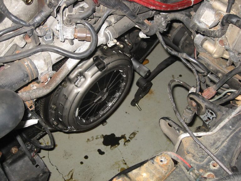
Remove the clutch. It is held on by I think 10 12mm bolts IIRC.
Step Sixteen:
Remove your flywheel. This is held on by 8 14mm bolts. I used an impact gun with a 14mm impact socket. These bolts are very tight and using a ratchet is difficult unless you can effectively stop the flywheel from rotating.
Step Seventeen:
Assemble lightened flywheel from stock ring gear, timing gear, and the stillen piece.
Step Eighteen:
Reassemble everything in reverse order, making sure to torque everything to spec and to replace the axle seals, and then refill with 4.8ish quarts of tranny fluid. DO NOT use an impact gun to install the flywheel and clutch onto the engine. These bolts are weak and can break…don’t ask me how I know.
Edit: Thanks to nismology for pointing this out, when refilling the tranny, do it with the car level on the ground and refill until oil comes out of the refill hole (It takes approximately 4.8 quarts)
Other notes…reinstalling the tranny was a major PITA since it’s so heavy. I recommend using a tranny jack. If you don’t have a tranny jack and if you aren’t super buff, you should remove the passenger side axle. It’s the same steps as the driver side with the addition of removing 3 bolts for the bracket that holds the axle to the engine.