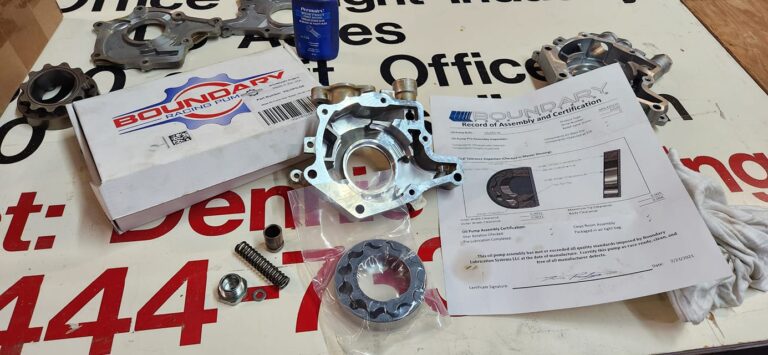
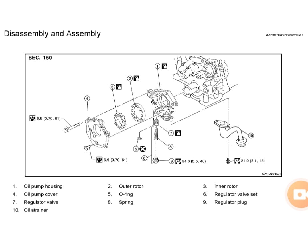
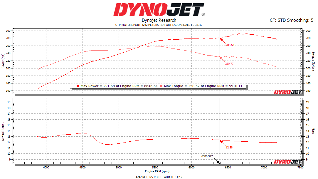
Boundary oil pump gears are 100% manufactured in our Dallas, Texas production facility. We start by quenching our chromoly billets from extreme heat and then temper it to tough indestructible core. After machining we apply our ColdFlow surface hardening process and complete it to a Mirror Finish. What does all this give you? It gives you a pump with stability over 9000 RPM, proven in excess of 900whp, with higher efficiency, less friction, and backed by one of the industries best warranty’s.
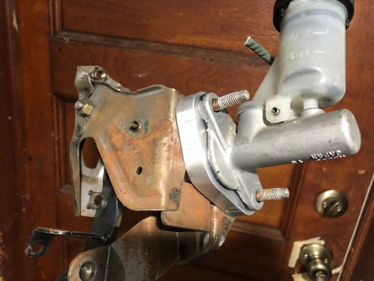
Kirill made a limited special run of clutch pedal spacers for 5-speed and 6-speed. This is a one piece 5/8 thick aluminum spacer, it gets installed on the inside of the firewall for auto to manual swapped Maxima’s.
$65.00 bucks shipped within the US. You can join my4thgen FB group for more details and ordering from Kirill (if there are more available). ALL SOLD!
Benefits:
If you’ve seen what’s spacing the clutch pedal in OEM form, anyone can benefit from this. The stock spacer is a tiny piece of bent steel, this provides a nice solid mounting point for the pedal, great for heady pressure plates. But keep in mind, if your car was manual when it was born, you’d need to drill out the stock spacer to use this. Auto to manual swapped cars, this is the best plug and play option. Great alternative to 5/8s worth of flat washers.
This describes removing and installing the rear O2 sensor behind the catalytic converter for 95-99 (Federal Emissions) Maxima/I30s.
Items Needed:
PB Blaster (or another rust penetrant)
22mm Wrench
Flat Head Screwdriver
Electrical Tape
Jack and Stands
Work Light
First, you will need to remove the bad O2 sensor. Use generous amounts (frequently) of the rust penetrant on the sensor where it goes into the exhaust pipe (bung).
While allowing the penetrant to work, follow the wire from the back of the sensor to where it goes into the floor panel. Use a screwdriver to pry the large rubber grommet from the floor pan. Once the grommet is loose, disconnect the plug that attaches the sensor to the harness.
Now use the 22mm wrench to remove the bad sensor from the bung. Continue using the penetrant as needed. This is the hardest part of the process (especially if you live in a snow state).
This is what you should be looking at once the bad sensor is removed.
Screw the new sensor into the bung and measure where the grommet will be positioned. Mark this position with a piece of electrical tape, and remove the new sensor from the bung.
Wrap the electrical tape around the wire cover on both sides of where it passes through the grommet. I added tape where the wire come out of the rear of the sensor.
Apply the anti-seize that comes with the new sensor to the threads; use plenty and coat all the threads, you’ll be glad if you have to do this again. Screw the new sensor into the bung and tighten with the wrench.
Attach the sensor clip to the harness.
Push the grommet back into the floor panel until you feel/hear the plastic backing catch, and the grommet is secured.
.org member Curt has come up with a unique way of mounting his 4th gen IACV with the swap, as well as routing hoses. Here is his idea…
Lots of discussion and controversy about where to route the air from the 4th gen. IACV to the UIM, and I don’t know if there’s any one answer. But here’s mine and the logic behind it.
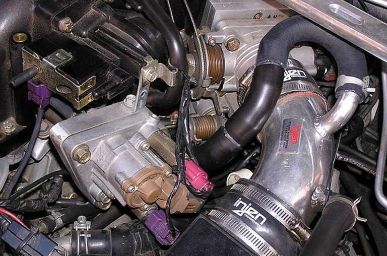
First, the what. I used the 4th gen. IACV with a Stephen Max adapter mounted hanging from the end of the VIAS. I kept the 3/8″ brass nipple that Steve had pre-installed, since I was confident in his experience and knowledge (and to also mention his intelligence in thinking these sorts of things through). The output hose from the IACV was routed underneath the UIM runners, exiting from under the #1 cylinder runner by the chain cover end of the engine, then looping around back to where the plastic nipple is on the end of the UIM that applies vacuum to the brake booster. I T’d the IACV hose into that line just above the plastic nipple.
Now, the why. Here’s the logic of why I tried (and have been completely satisfied with) this setup. An engine is, in simple terms, and air pump. These 3 liter engines at idle try to pump almost one cubic foot of air per second. With the TB butterfly closed, the engine is straining to suck in air from wherever it can get it.
On startup it initially gets only a tiny amount from the brake booster as all that’s really happening is creating a vacuum within the brake booster. And even if the engine sucked all of the air out of the booster (in effect creating a perfect vacuum), that would only be a fraction of one cubic foot. Secondly, once there’s a vacuum created in the brake booster there’s a check valve in the vacuum line between the UIM and the brake booster that’s intended to keep the booster from losing the vacuum.
Now let’s assume that you’re cruising down the road with little vacuum in the UIM (in other words, heavy throttle) and for some reason the brake booster has been having its vacuum bleed off. If you were to try to brake with your left foot as you kept the right foot on the accelerator (not recommended), the brakes wouldn’t likely have the boost assist necessary and stopping would be a problem. But it used to be that most people learned to drive using their left foot only for the clutch so that if sometimes they were driving a MT car and sometimes an AT car, they wouldn’t get their feet confused in a panic situation.
So, properly using you right foot to stomp the brakes, even if the brake booster had been real short of vacuum when your foot was on the accelerator, as soon as you lifted it to apply the brakes, the butterfly plate in the TB would have closed and in an instant there would have been good vacuum in the brake booster unless there was sort of a problem beyond the check valve at the booster (and having the IACV plumbed into the booster line wouldn’t affect that kind of a problem anyway). Simple logic persuaded my to try this setup and I’ve had no regrets.
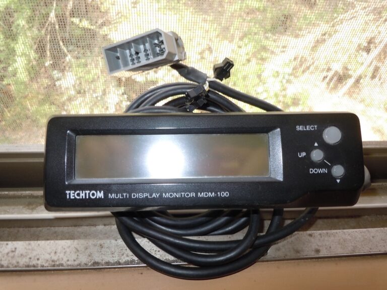
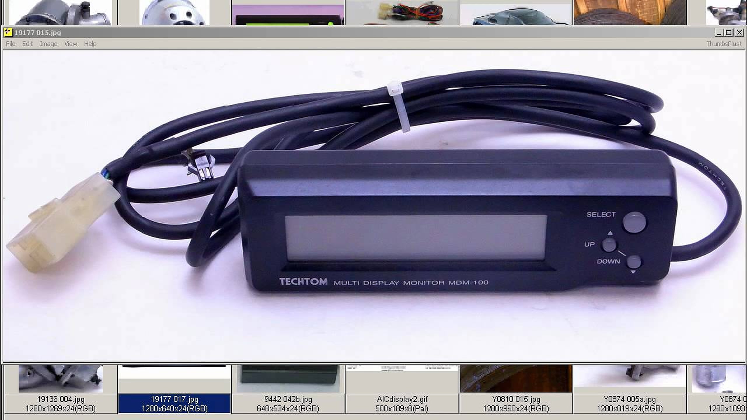
A Techtom MDM-100 Monitor allows the driver to view a number of engine sensor parameters in real time using ECU data. It is plug-n-play and installs in seconds! Long recognized as the most advanced monitor for Nissans, the MDM-100 allows you to watch two different parameters/sensors at the same time, and in real time.
Important Note: This only works on 1995-1996 Nissan Maxima ECUs.
Within seconds you can have the MDM-100 plugged in and displaying engine readings on its easy-to-read backlit LCD. You can see 2 sets of readings on one screen. Additional ECU data is easily obtained using the easy-to-operate 3 button control. Examples: Speed and Water Temp Battery and Ignition Timing.