Member Credit: Metal Maxima
Alright, as my final HOW-TO on the .org, I am going to be detailing how one can black out your headlights and add the newly coveted Audi LED effect to your headlights. Without much adeiu, let’s begin!
ITEMS NEEDED:
- Flexible LED strips from Oznium ($40)
- Amazing Goop from Home Depot ($4)
- About 5 hours…this is actually a pretty quick mod
STEP #1
Remove headlights. I am not going to detail this, there are two screws to remove that are exposed at the bumper level then just pull out…HARD.
STEP #2
You’re going to need to remove some hardware from the headlights before beginning. All rubber components, bulbs, and any screws that will come out. One universal item the bulbous thingie that was a beotch to remove in the previous step.
STEP #3
Obtain a flat baking sheet and a large towel. Wet the towel so it’s wet, but not dripping wet. Drape across the entire length of the sheet. TEST FIT THE SHEET WITH THE HEADLIGHT IN POSITION. Once you’re comfortable with the fit, preheat the oven to 250F. Place the headlight facing UP.
STEP #4
Bake for 10-12 minutes, ONE AT A TIME. Feel free to nervously pace the kitchen floor. *DING* That’s the sound of opportunity! Take your headlight out. I recommend using leather gloves, you’ll need the dexterity. Start by removing the two screws where the bulbous thing is…they are easier to remove once the adhesive is at working temp. Pry your headlight apart by using a flathead screwdriver to pry the mechanical attachment points open. Then pull…I only did 10 minutes and pulled…hard.
STEP #5
Remove the chrome components from the body. Here’s a shot of the only two screws for the 5th gen. The 5.5 gen will have more, sorry, I have limited pics of the 5.5gen. NOTE: Your lens portion will need to be warm for the 5th gen shroud to be removed; this allows proper expansion…believe me, it ain’t coming out otherwise.

You’re going to want to tape the chrome sections you want to retain. This is actually easier then it sounds. Use small pieces when going around the corners. TIP: Take the tape and slowly walk it across the contours…you will have 0 difficulties if you do so.

STEP #6
Paint using Duplicolor’s High Temp Engine Enamel. Do 3 coats; two light coats at about 12″ distance, very quickly. Do a third “wet” coat; you can do multiple light coats, but I’ve used close to 100 cans of spray, so I have an unfortunate familiarity with how it behaves. Allow 2 hours cure time, then peel away.


STEP #7
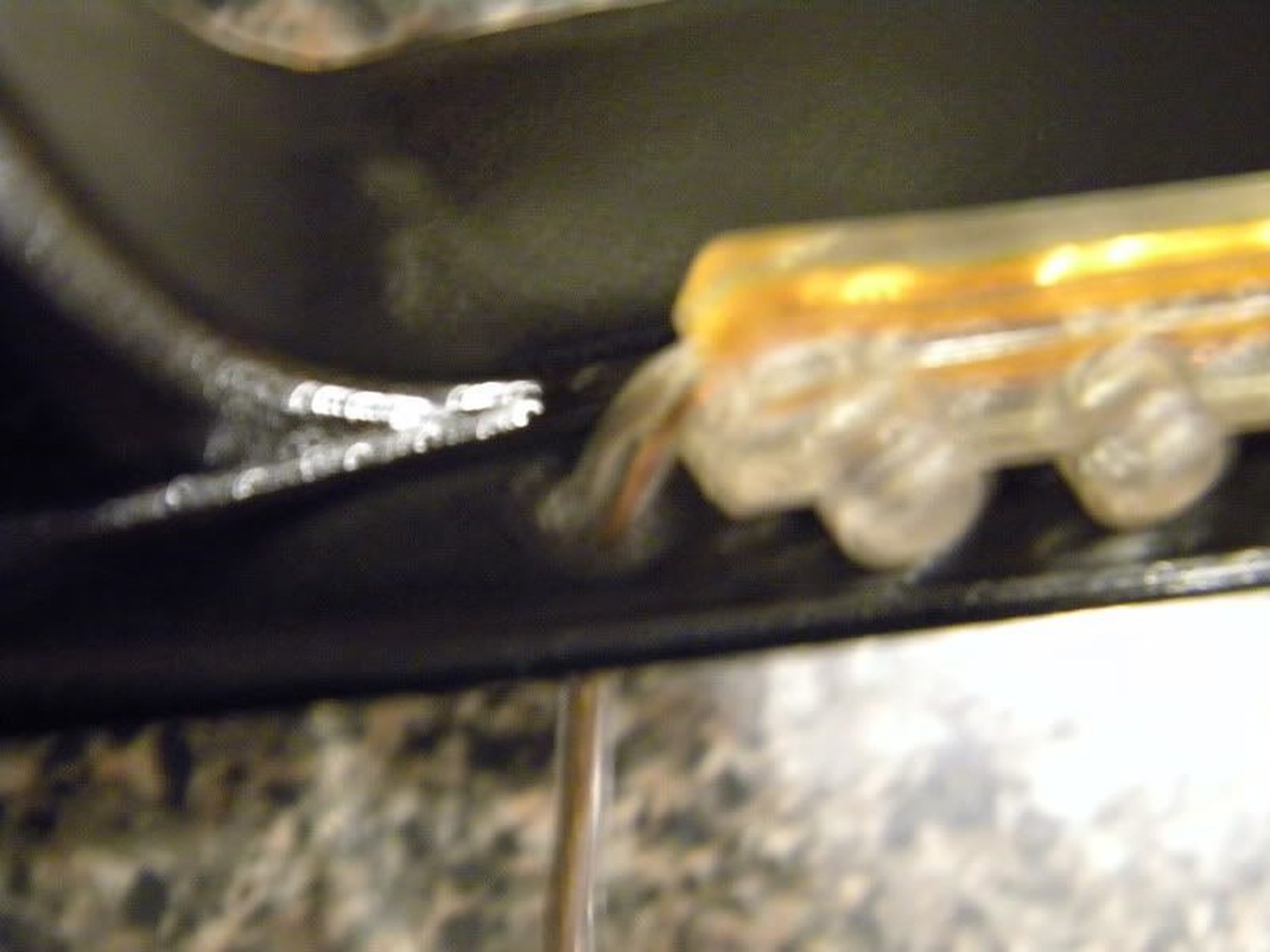
Cut your LED strip to size and attach it using the double-sided tape included. One the 5th gen, you’ll use 21 LEDs. The 5.5 gen is considerably more, just cut to size. NOTE: The array on the strip is in denominations of 3, so you must have a multiple of 3 in order for the full length to light!!! (i.e. 36, 33, 30, etc.)
STEP #8
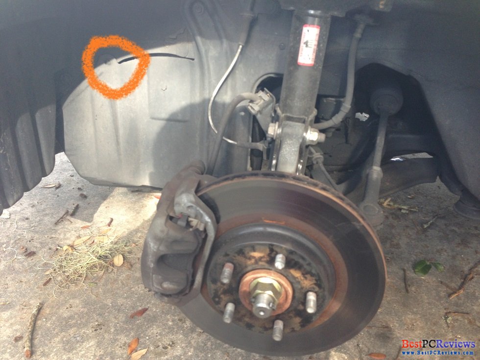
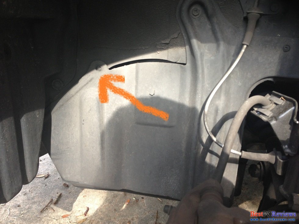
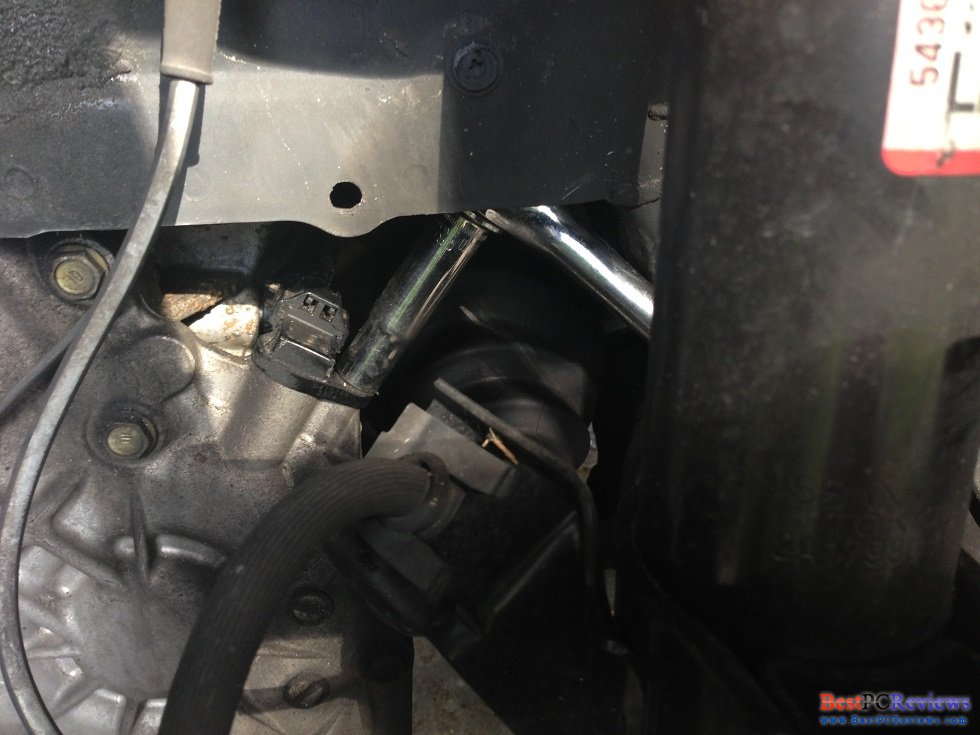
Drill a small hole to allow for wire passage…I did mine as seen here on the 5th gen…I recommend going toward the turn signal as it is less readily seen below:

STEP #9
Now this is what I consider to be the hardest step. In order to properly reseal, we need to reuse the existing sealant. SO, back in the oven we go…ONLY PLACING THE LENS AND BODY IN THE OVEN. Do so at 250F for 10 minutes. You’re going to want to leave the body face up as the channels will likely contain the largest portion of sealant. Remove when the adhesive is glossy, meaning it’s at working temp.

STEP #10
While everything is hot, QUICKLY reassemble. Be confident, you can do it. You’ll need to do this for the proper seal. Push the body and lens together, making sure the mechanical tabs properly latch. Route the wire behind the lens shroud, you can drill your own hole or use the vent line aperture.
STEP #11
*WHEW*, ok, so you got the lenses probably 80% sealed. Time for some GOOP! Add some extra sealant, we’ve done all this work and don’t want to blow it now.

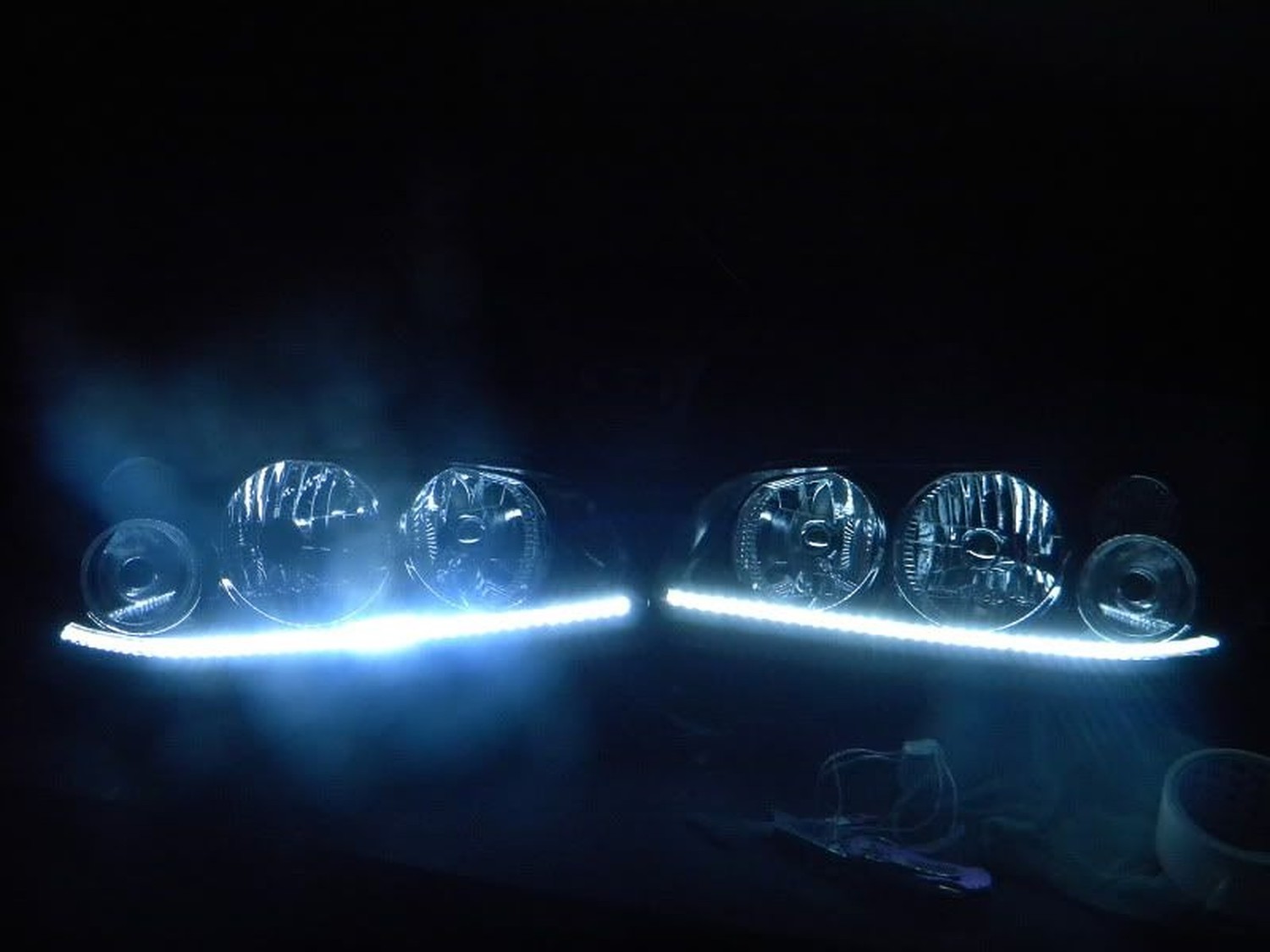
STEP #12
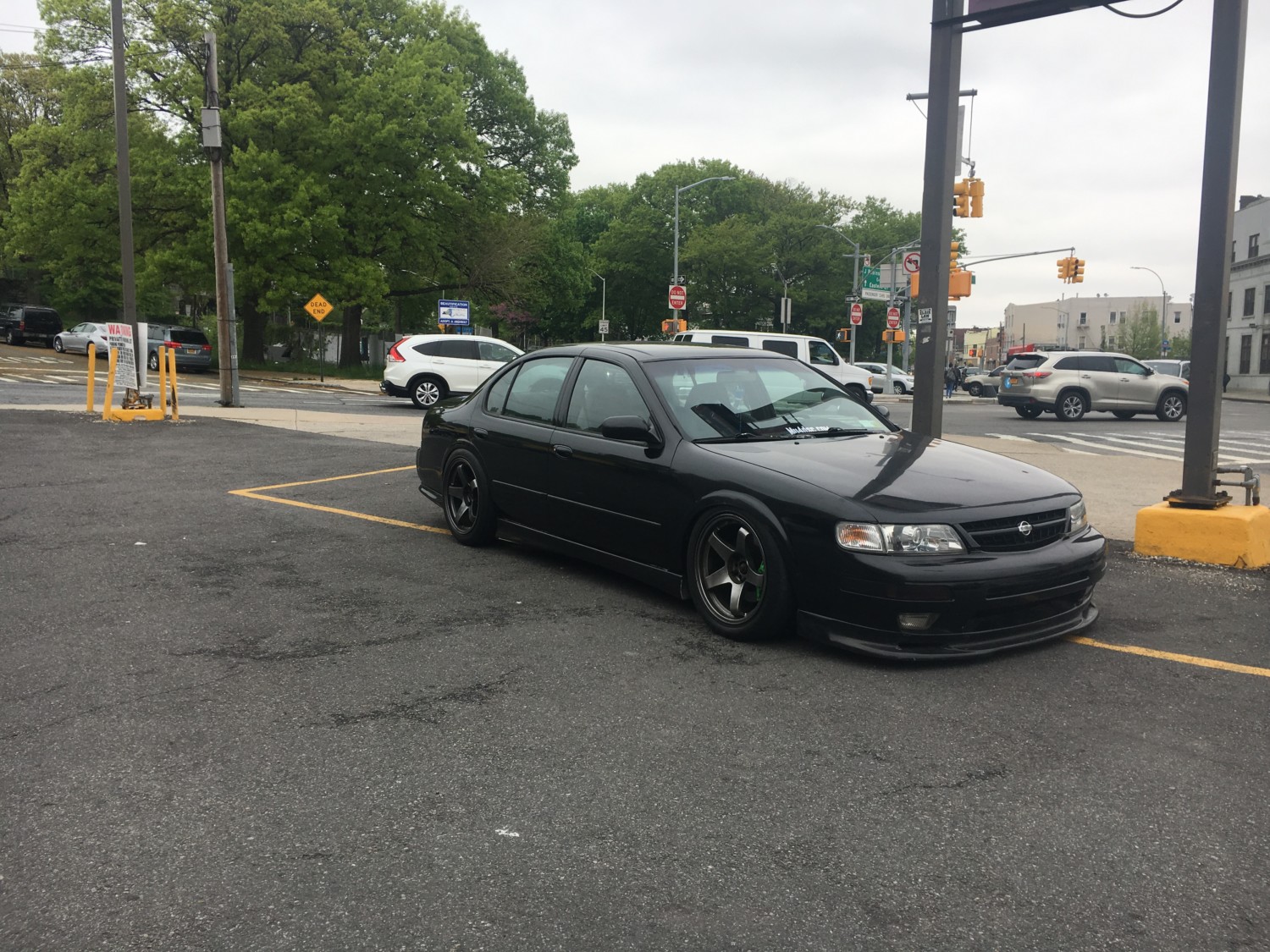
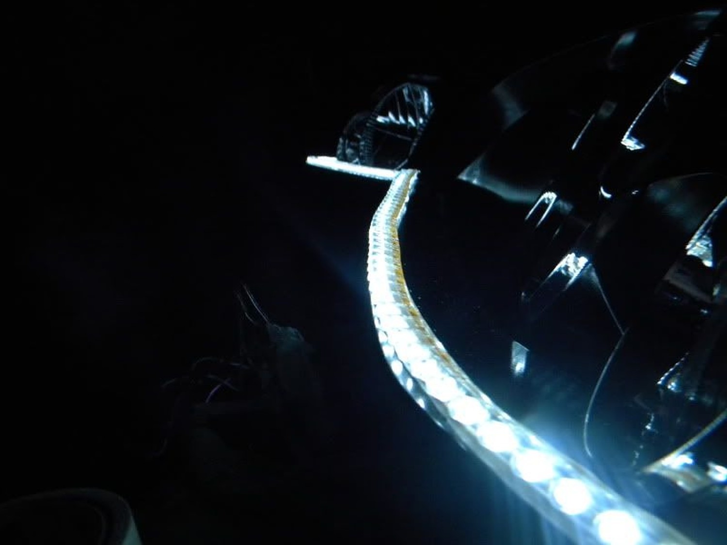
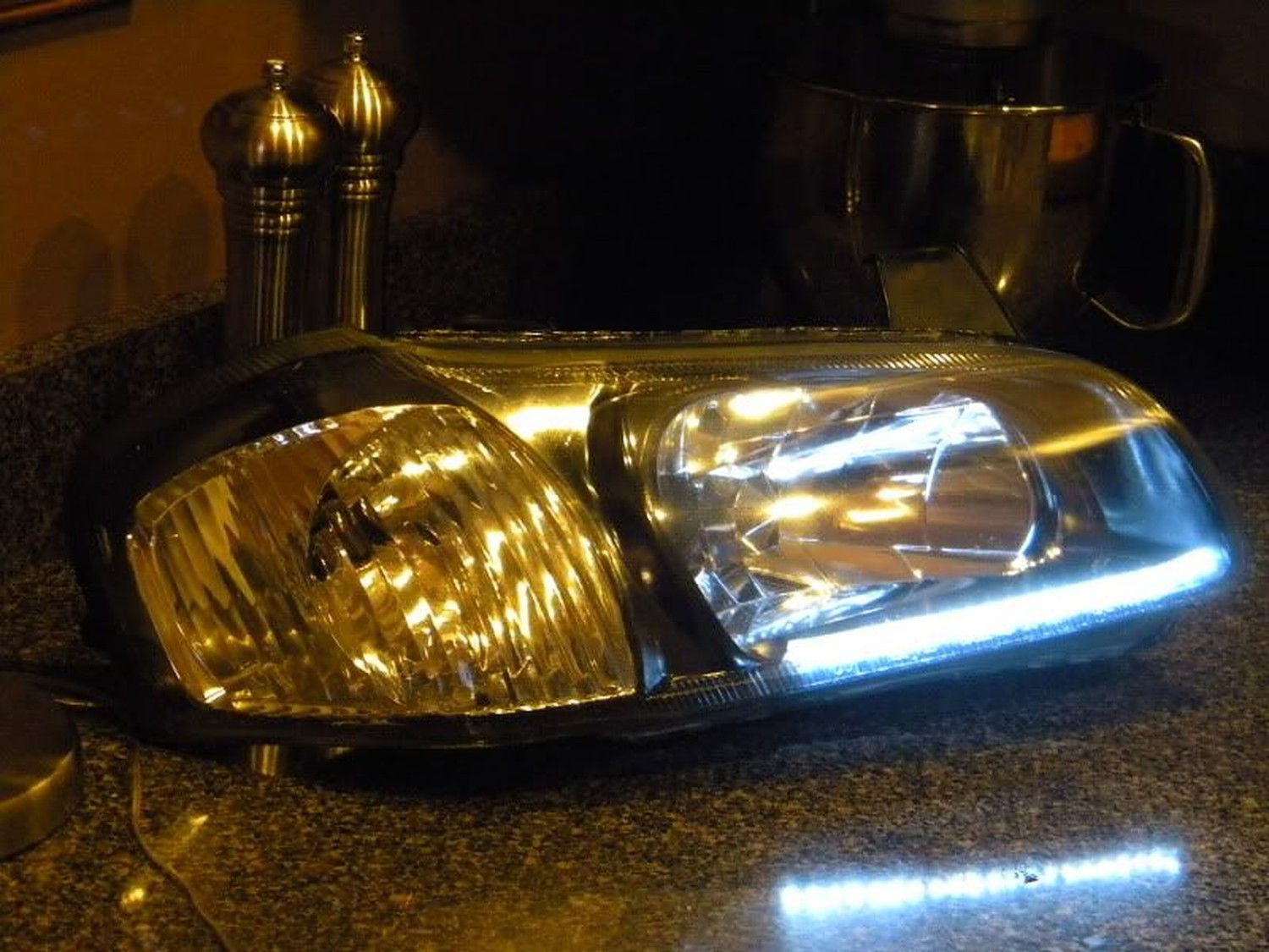
FIRE IT UP! Test with a 9V to enjoy the awesome effect. These things are BRIGHT!

![]()


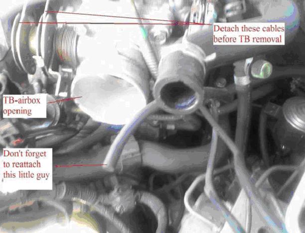

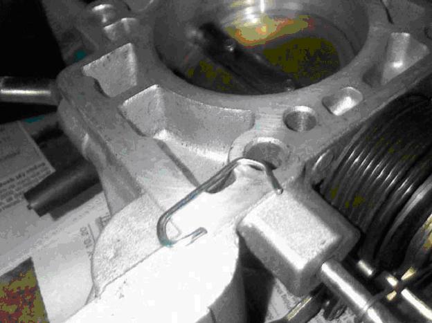
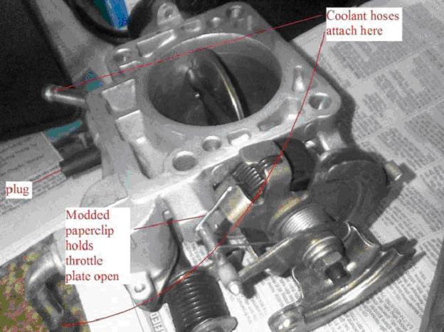
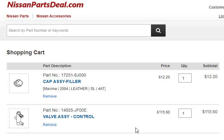
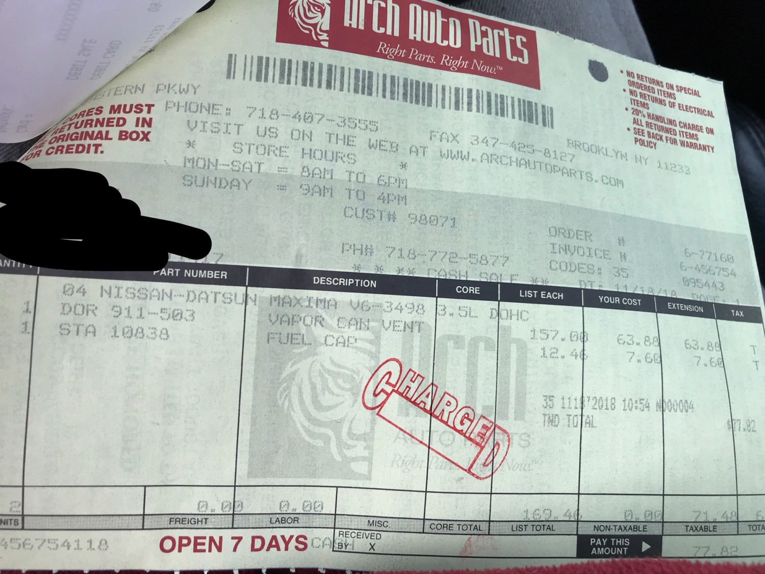
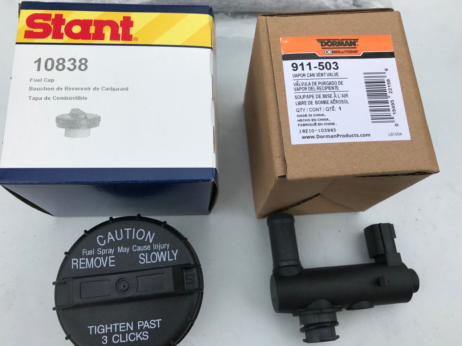
 IACV:
IACV: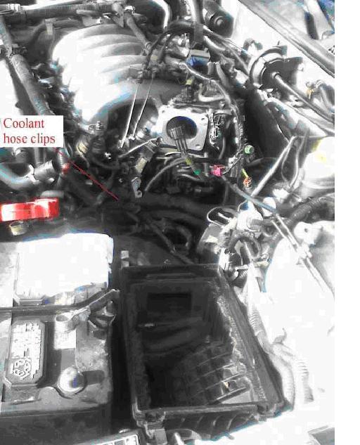


 2004-2008")