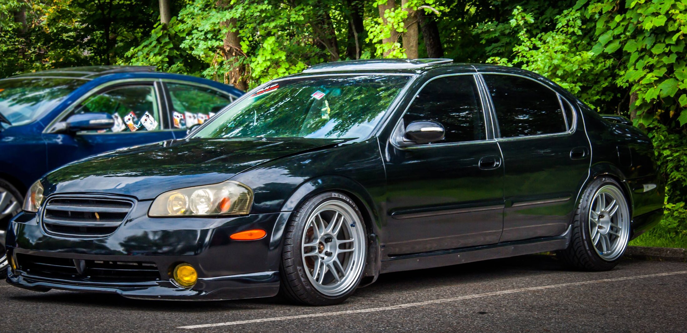
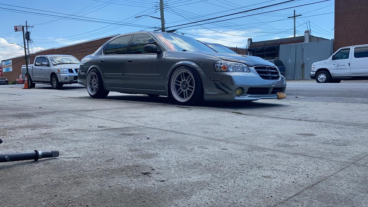
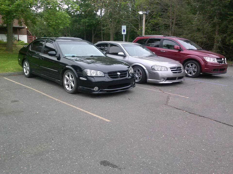
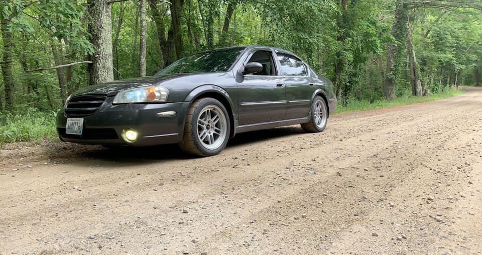
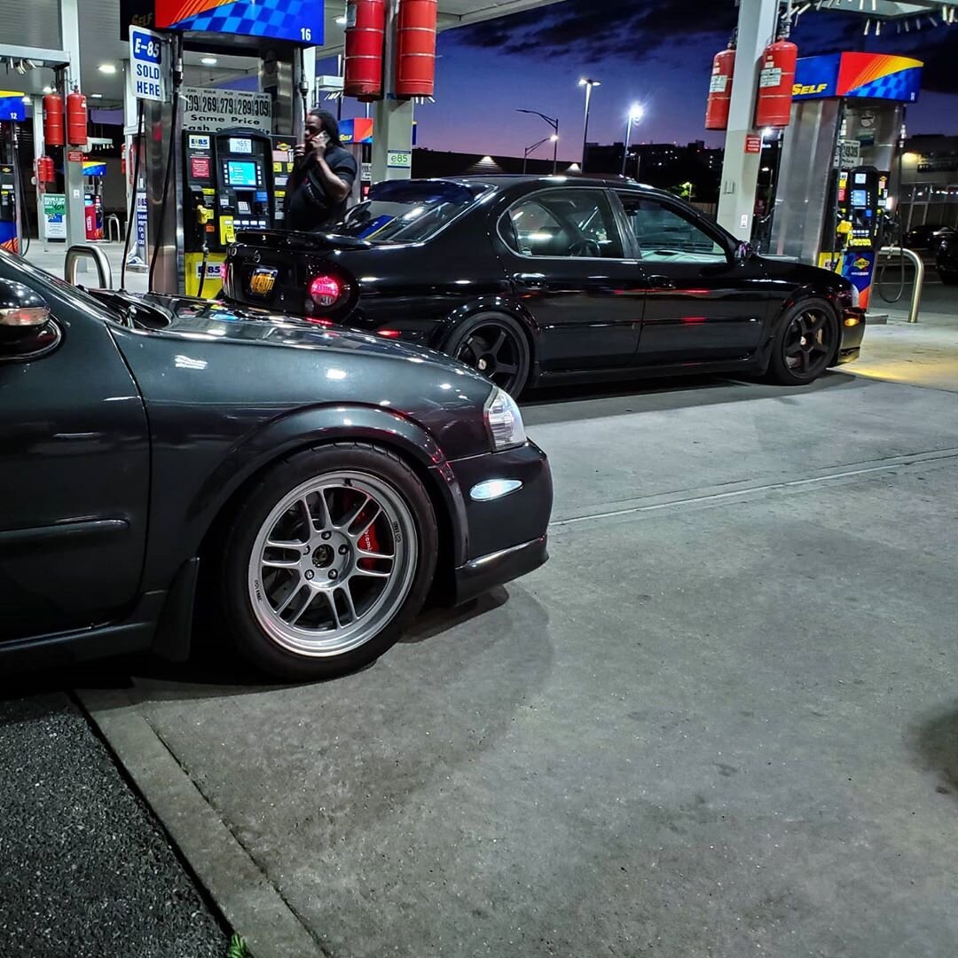
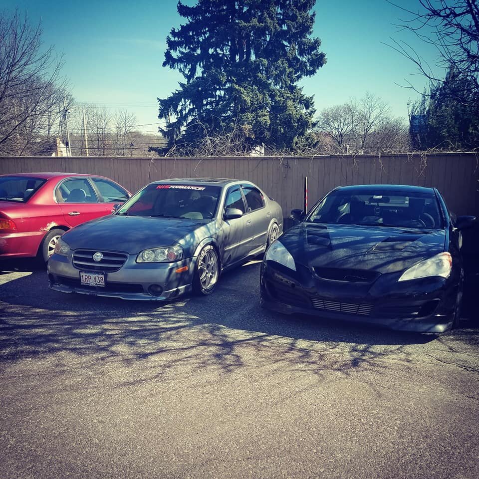
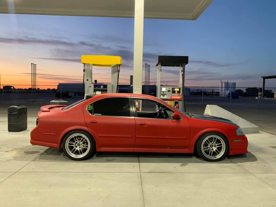
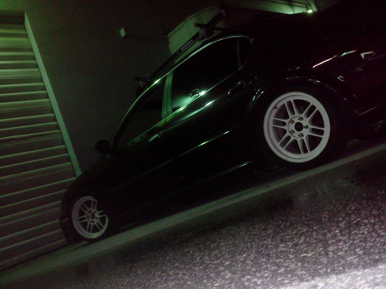
Gallery of Enkei RPF1 Wheels on 5thgen Nissan Maxima
![]()
Credit: EddyMaxx
It’s usually easier to buy the whole pedal. But if you get this code, it’s very likely your issue is your accelerator pedal sensor. I was driving on the way when all of a sudden my car lost power and I couldn’t accelerate. If you choose to buy the sensor, you can reference the part numbers below.
Order Link: https://ebay.us/nZcm1f
Interchangeable Part Numbers:
Issue Symptoms:
Reference Photos:


![]()
Member Credit: tjmoney87
Overall, this is an easy mod if you are careful, but if not, things can get ugly VERY quickly! I would recommend getting a second cluster just to practice…that’s what I did, making sure I was careful enough and to make sure the strip fits. I like it because the cluster lights in ACC mode, but that’s a personal preference (also because the cigarette lighter powers in ACC mode). Also at night, they are BRIGHT (but not bright enough to blind), and do not dim, unless you get a standalone rheostat, I may get one later…I wish I would have got an orange or red one, it would have really nice, but I can always change it out LOL… Also, I would recommend the Maxima’s clear outer cluster cover, http://www.courtesyparts.com/24813-c…3-p-47148.html, our tinted cluster cover would dull things a bit…
Difficulty: 7/10
Pros: LED strip brighter than EL tube, no more dim cluster on one side !
Lights in ACC mode (personal preference). Several colors you could use (again personal preference).
Cons: If you are not careful, things can get ugly quickly! You will have to buy the Maxima’s cluster to enjoy the LED cluster.
Stock

After LED strip swap

My mom’s ’09 Altima

An ’09 Camry

1. Take the cluster out of the car (this should be self-explanatory).

2. Take the outer cover out of the cluster (be careful, it is easy to break!)

3. Remove inner cover (black part) out of the cluster.

4. By now you should see all of the screws to remove the gauges.

5. Removed the circuit board cover to make everything easier…

6. Here you can keep the gauges together as one after pulling up, or you can have them separated (which I did) by removing screw on the bottom of the speedo and tach.

7. Before removing speedo head, remove odometer head. PLEASE be careful, that odo head is on their pretty tough it would be easier to break the tab rather than the odo head!

8. Here is the EL tube and all it’s glory…

9. These are the screws to remove the EL tube…

10. Pull up on the tube assembly and it should come out of the cluster’s circuit board.

11. Here is the room you have to work with…it’s not much, but the LED strip I ordered from http://www.oznium.com/led-flex-strips fit like a glove. I used super glue to hold it together. Also the wires from the LED strip can be snaked through the holes left from the EL tube screws…

12. Put everything back together and tighten everything up. Use a 9V battery to make sure the strip lights up…

13. With everything back together…

It’s wasn’t bright at all (especially in the daytime) but it was on a 9V battery so…
I decided to wire it up to the cigarette lighter…yes the gear shifter surround has to be removed and the radio/ climate control too, or enough to get to the cigarette light wires…


Wire the LED strip wires together with the cigarette lighter and put key in ACC to make sure it lights…it’s very bright in the daytime… Especially at night they are amazingly bright!
After only 4 years my replacement CCFL had dimmed to the point that I couldn’t see the display when the car was very cold. It was only poorly visible even when warmed up so I decided to finally install LED’s. I did this with a bit of hesitation because I could not find the cluster wiring points for LED’s posted anywhere, despite hours of searching. With some work I was able to figure it out.
The LED strip and an extra connector was purchased from superbrightleds.com for less than $20 with shipping.
1 – NFLS-NW30X3-WHT Natural White LED Strip (includes 1 connector)
1 – NFLS10-2CPT Pigtail Connector
The LED strip has adhesive backing and can be cut every 2″. I pulled the old CCFL, associated wiring and circuit board and mounted two 4″ strips right to the CCFL plastic mount, one on either side of the transmission display. I placed them as close to the outside edge of the plastic as possible. They fit almost perfectly, only a tiny piece of plastic had to be trimmed from the mount. The wiring from the strips fit into the same run that the CCFL wiring ran through. I soldered the wires together.
I wanted the wiring to remain contained inside the cluster so I spent a few hours examining the schematics in the FSM and found the correct wiring points:
The wiring connection points are on the plug labeled M34, shown on page EL-145 of the FSM. It is fairly easy to solder wires directly to the pins on the base of the connector if you tin both the wire and pin first.
The negative LED wire connects to pin 49. That lead connects directly to the Illumination Control Switch (the dimmer control.) The FSM pages showing the wire endpoints are EL-120 and IL-123. The path of the wire runs across multiple pages of the schematic.
The positive LED wire connects to pin 66. Pin 66 connects to a 12V source that is controlled by the ignition key. It’s shown on manual page EL-147.
The results were well worth the time. For the first time the cluster lights look like they should, clearly visible in bright daylight even with sunglasses on. The odometer is also clearly legible all the time. When the headlights are turned on the cluster LEDs dim exactly as they should. The color of the LED strip is also excellent and lacks the purple hue of the last CCFL bulb I installed.
The only negative is very minor. The lighting across the display isn’t quite as consistent as it was with the CCFL. It is a minor variation and I don’t think I would have noticed it at all if I hadn’t been looking for it.
Good luck.
Update: After driving the car for a few days in the daytime and being very pleased with the brightness of the display, I drove last night after dark. The new LED’s are so bright that to get them down to a reasonable level at night requires turning the dimmer way down, too far down to clearly see the other displays that are also controlled by the dimmer. Unfortunately it won’t be possible to contain fully contain the wiring withing the cluster and maintain the daytime brightness without adding a custom circuit. To allow the independent control of the cluster LED’s I’ve decided to add a 2nd dimmer switch dedicated to the LED lights. Ebay had one for $12 shipped and I have an empty spot in the dash to install it so it looks like a stock control. I’ll post back here with results.
![]()
Credit: Voltaire Duran Cacal / @DMVOLT
Production Description: 2006 – 2007 Impreza WRX STI V-Spec Polyurethane Front Bumper Lip by GT-Speed
Price: $139.95
Order Link: https://www.amazon.com/dp/B004N9WKHU/ref=cm_sw_em_r_mt_dp_U_8YL5EbZD2HEQE


![]()
Member Credit: Eddy
If you are buying the Cefiro Power mirrors, you have two options to enable the power-folding feature. You can use the OEM switch or use your own. In many cases, whoever is selling the mirrors usually provides the OEM switch needed. But that is not always the case. I got my Cefiro mirrors for $80 bucks at an awesome deal but it didn’t have a switch.
Originally, I was looking to buy the OEM switch and I saw they ranged from $60-90 bucks. Given that, I decided to go my own route. There are probably other ways as well but this was best for me. I also got the turning signal, puddle lights, and heated functions to work as well.
Below is the OEM Switch if you wanted to go that route.

Below is the switch I used. I honestly like that I control how much up/down I want to go. And for a few bucks, I can live with manually moving up/down. I’m sure you can get these locally or cheaper but this is the type I used.

Here you can see I’ve wired up the jumpers for +12v Power and Ground. The two unplugged left/right pins in the middle are for your Orange and Pink wires from the Mirrors. The Orange and Pink wires are what allow you to put the mirrors up for down (you need to do for both Left/Right mirrors).


Clean look for the toggle switch.


Here you can see how I labeled the wired. The orange wires are really supposed to be, 1-orange and 1-pink. But this is how the mirrors came.

Video of everything working.
![]()
Credit: Rene Saran
This setup is 2″ from the eBay headers, stepped to 2.25″ into a slip connector that goes to 3″ all tig welded stainless a d vibrant everything. The work was done by Centerline Motorsports.


![]()
Credit: Fezzik (David Honey)
This is the How To on the installation of heated mirrors. A few things first before I go on. I have the automatic climate control with the rear window defogger switch on it. The side view mirrors are linked to this switch. For those with manual climate control, I assume that it is also linked to your rear defogger switch (RichK on maxima.org said he got the same reading as I). Total costs are as follows quoted from Dave Burnette (1-888-254-6060):
Mirror Heater Relay = $12.22
Side view mirror glass with heating element only = $45.72 per side
First of all. Make sure you do not have the heated mirror option. To make sure, you can either press the rear window defogger switch and put your hands on the mirror to see if it gets warm or pop off your side view mirror glass and see if you have wires running to the mirror itself. If you do, then you have this option already. The picture below is one showing the difference in the two mirrors. The right does not have this option and the left mirror does. You will have to purchase the mirror on the left because it has a heater element built into the glass mirror.

If you do not, then follow these instructions to get them. First of all, open your hood and when looking at the engine bay look to your left and you will see a black box that contains some relays. Open that up and find the corresponding spot for the heated mirror (it says on the black box where its at.) If you have a spot to put a relay in then all is well so far, and later you will have to buy the relay or in my case I had a nice surprise and already had the relay there. Ok the next criteria you need to find out in order for you to proceed is to take off your door paneling and look at the wiring harness going to the side view mirror (see below pic). The big black plastic piece is the cover to the side view mirror. There are 3 wires (yellow purple and dark blue) going into this and into the side view mirror. There are 3 wires corresponding to these wires on the other side of the connectors. Now take note of the other 2 wires (Green and light blue) coming out of the top right two holes. There is normally nothing here, but on the corresponding other side there are two wires leading up to these.

These are the wires that are pre-wired for the heated mirror. I tested this theory out by hooking up a voltmeter to the wires that I put in the top right holes. (I originally had the connector in the above picture disconnected and tried to test the voltage on the 2 small pins and that was too hard to do. I shorted the circuit and blew fuse 13… so do like I did above. SO much easier). When plugged into a voltmeter and with the rear defroster on I got around 12 volts (sorry about the blurry pictures):

And with the rear defogger switch off reads 0.001Volts:

The next step is to take off the black plastic cover that is covering the side view mirror bolts (same plastic cover as seen in the above picture that the 3 wires are running into.) Unplug the connector, and take off the three bolts that are holding the mirror onto the door.
What it looks like with the mirror off (inside). Also notice how many wires are running into this connector. Look below the black tape. 5 of them.

Outside view with mirror off:

Now you have to take out the 3 screws that are below the side view mirror.Notice the blue. Yep that’s locktite. I striped the head of the screw on the passenger side and took me 2 hours to finally get it out. SO BE CAREFUL TAKING THESE OUT:

Here is the assembly all apart:

Now look at the part of the side view mirror that faces the car the part that has the 3 places to bolt onto. There is a cover on this that you have to take off. The insulation is glued on there so your going tear that. Nothing you can do about that. Look below how I tore mine. Unscrew the thing that is holding the wiring harness in place.

I apologize but I forgot to take some pictures from here on out. It was getting late. But now, you can have full access to this gray tubing. Remove the actuators (the things that make the mirror go up and down, right and left) from the side view mirror. This is held on by 3 screws. When you take this off you will see 4 wires. Didn’t I just say there was 3 wires going to the side view mirror. I did. But one is spliced somewhere in the gray tubing. Dave Burnette (You maxima guys should know him) and I were talking about this for awhile until I finally found out the reason The ECM even shows 3 wires but if you look inside the actuator, there is a wire that is split. Ok back to the subject at hand. Remove the 2 connectors (gray and black) from the actuator. Remember which go where. I marked it with scotch tape. Now the wiring can slide down the tube that is inside the mirror. Wish I had a pic of this but you will see what I am talking about. Now you can run wire through the gray tubing easily.
First I ran 2 wires long enough to reach from the other end of the side view mirror where the heater element connector is to reach all the way to the connector in the door panel.To run wire through this gray tubing was tricky, but I used solder wire. The stuff that’s flimsy. Well, it’s stoutenough to push the solder wire through the grey tubing. Then I tied ( you may try taping it) to the wire and pulled it through. You now have a wire going all the way through. Now put everything back together the way you took it off. I did not worry about the insulation from the above picture because it all went back and even though it is torn still covered everything up. Now that everything is back together you now have what you started with but, now with 2 wires running through the mirror. Here’s the part where I had to get creative. You have to have a metal pin connector to fit into the big plastic connector. Luckily I have a storage area of computer parts and wiring harnesses from computers. I actually got the 2 pins I need from a 1985 Honda Accord radio wiring harness for aftermarket systems. Lucky me. Now all that leaves is the connector for the side view mirror. Take a look at it below:

Of all things I found to fit into here… it was a long computer jumper. Sorta like the audio cables you plug from your cd drive to your sound card, but I had a 2 prong one. With a little bit of firm pressure it fit right in and quite snugly. Popped the mirrors back into place and I now have heated side view mirror option on my car. Supposed to snow soon. Can’t wait to try it out.
Special thanks go out to my dad for helping me decipher the wiring diagram on the ESM and reading the voltage, and to Dave Burnette for his time in this as well.
![]()
Credit: Eddy
I wanted to add some lightening to my engine bay so I got a set for $20 bucks at Walmart. I mounted the LED strips on the sides so I can better see the supercharger itself and belt. I wired them up to a separate switch to manually turn them on/off as needed.
They also have the same LED strips for $10 bucks at Walmart without the cigarette lighter adapter which you don’t really need. However, they didn’t have those in stock so I went with these. Happy with the overall turnout. Looks really good at night.


![]()
Member Credit: perkman87
I have has multiple emails on the Navi install on my 2003 maxima via taking out the ashtray. The Navigation Model is the Magellan Maestro. It matches the TE edition perfect as you can see it is also silver and black just like most interiors in the SE family.
All I did was run the power from the rear socket spliced it in, then cut a small hole in the side of the ashtray holding container. Taking out the ashtray was simple you just unscrew the center screw in the middle of the ashtray, then pop the whole shifter cover off (holds ashtray) and there will be 4 screws that hold it in place, take those out and the ashtray box will come off with ease.
There are tabs on the side of the ashtray that will allow you to take the slider off with ease, then just go ahead and cut the side of the case with a warm knife, and slide the power connector through.

![]()